Embed Size (px)
Citation preview
3-870-286-13 (1)
© 2008 Sony Corporation
Wireless Microphone Package
Operating InstructionsBefore operating the unit, please read this manual thoroughly and retain it for future reference.
UWP-V1/V2/V6UWP-X7/X8
2
For the UTX-B2/H2/P1 Transmitters
Owner’s RecordThe model and serial numbers are located at the rear or on the bottom of the unit. Record the model and serial numbers in the space provided below.Refer to these numbers whenever you call upon your Sony dealer regarding this product.Model No. _____________________Serial No. ______________________
WARNINGBatteries shall not be exposed to excessive heat such as sunshine, fire or the like.
IMPORTANTThe name plate is located on the bottom and the serial number is located inside the battery compartment (UTX-P1).
Notice for customers in the U.S.A.Use of Sony wireless devices is regulated by the Federal Communications Commission as described in Part 74 subpart H of the FCC regulations and users authorized thereby are required to obtain an appropriate license.
You are cautioned that any changes or modifications not expressly approved in this manual could void your authority to operate this equipment.
IMPORTANT NOTE: To comply with the FCC RF exposure compliance requirements, no change to the antenna or the device is permitted.Any change to the antenna or the device could result in the device exceeding the RF exposure requirements and void user’s authority to operate this device.
This device complies with FCC radiation exposure limits set forth for uncontrolled
equipment and meets the FCC radio frequency (RF) Exposure Guidelines in Supplement C to OET65. This device has very low levels of RF energy that it is deemed to comply without testing of specific absorption ratio (SAR).
Notice for customers in Canada:Use of Sony wireless devices is regulated by the Industry Canada as described in their Radio Standard Specification RSS-123.A licence is normally required. The local district office of Industry Canada should therefore be contacted. When the operation of the device is within the broadcast band, the licence is issued on no-interference, noprotection basis with respect to broadcast signals.
Operation is subject to the following two conditions: (1) this device may not cause interference, and (2) this device must accept any interference, including interference that may cause undesired operation of the device.
The term “IC” before the radio certification number only signifies that Industry Canada technical specifications were met.
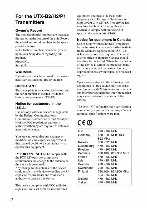
U.K. 470 - 862 MHzGermany 470 - 606 MHz, 614 -
862 MHzNorway 800 - 820 MHzLuxembourg 470 - 862 MHzBelgium 470 - 862 MHzDenmark 800.100 - 819.900 MHzFrance 470 - 830 MHzItaly 470 - 854 MHzSweden 470 - 862 MHzSwitzerland 790 - 862 MHzFinland 790.100 - 821.900 MHz,
854 - 862 MHzIceland 470 - 862 MHzTurkey 470 - 862 MHz
Notice for customers in EuropeHereby, Sony Corporation, declares that this UTX-B2/H2/P1 is in compliance with the essential requirements and other relevant provisions of the Directive 1999/5/EC. For details, please access the following URL: http://www.compliance.sony.de/
This product is intended to be used in the following countries : United Kingdom, Germany, Norway, Luxembourg, Belgium, Denmark, France, Italy, Sweden, Switzerland, Finland, Iceland, and Turkey.
Note:In some countries additional frequency bands may be used with the agreement of the national authority.
Voor de klanten in EuropaHierbij verklaart Sony Corporation dat het toestel UTX-B2/H2/P1 in overeenstemming is met de essentiële eisen en de andere relevante bepalingen van richtlijn 1999/5/EG.Nadere informatie kunt u vinden op:http://www.compliance.sony.de/
Dit product is bedoeld om in volgende landen gebruikt te worden: Verenigd Koninkrijk, Duitsland, Noorwegen, Luxemburg, België, Denemarken, Frankrijk, Italië, Zweden, Zwitserland, Finland, IJsland en Turkije.
Opmerking:In bepaalde landen kan er gebruik gemaakt worden van aanvullende frequentiebanden, mits toegestaan door de nationale instanties.
For kunder i EuropaHärmed intygar Sony Corporation att denna UTX-B2/H2/P1 står I överensstämmelse med de väsentliga egenskapskrav och övriga relevanta bestämmelser som framgår av direktiv 1999/5/EG.För ytterligare information gå in på följande hemsida: http://www.compliance.sony.de/
Den här produkten är avsedd för användning i följande länder: Storbritannien, Tyskland, Norge, Luxembourg, Belgien, Danmark, Frankrike, Italien, Sverige, Schweiz, Finland, Island och Turkiet.
Observera:I vissa länder kan det hända att ytterligare frekvensband används efter överenskommelse med det landets myndigheter.
Para os clientes da EuropaSony Corporation declara que este UTX-B2/H2/P1 está conforme com os requisitos essenciais e outras disposições da Directiva 1999/5/CE.Para mais informacoes, por favor consulte a seguinte URL: http://www.compliance.sony.de/
Este produto destina-se a ser usado nos seguintes países: Reino Unido, Alemanha, Noruega, Luxemburgo, Bélgica, Dinamarca, França, Itália, Suécia, Suíça, Finlândia, Islândia e Turquia.
Obs.:Em alguns países uma faixa adicional de frequências pode ser utilizada com autorização do governo nacional.
For kunder i EuropaUndertegnede Sony Corporation erklærer herved, at følgende udstyr UTX-B2/H2/P1 overholder de væsentlige krav og øvrige relevante krav i direktiv 1999/5/EF.For yderligere information gå ind på følgende hjemmeside: http://www.compliance.sony.de/
Dette produkt er beregnet til brug i de følgende lande: Storbritannien, Tyskland, Norge, Luxembourg, Belgien, Danmark, Frankrig, Italien, Sverige, Schweiz, Finland, Island og Tyrkiet.
3
4
Bemærk:I nogle land kan yderligere frekvensbånd blive anvendt med de nationale autoriteters samtykke.
Euroopassa oleville asiakkailleSony Corporation vakuuttaa täten että UTX-B2/H2/P1 tyyppinen laite on direktiivin 1999/5/EY oleellisten vaatimusten ja sitä koskevien direktiivin muiden ehtojen mukainen.Halutessasi lisätietoja, käy osoitteessa:http://www.compliance.sony.de/
Tämä tuote on tarkoitettu käytettäväksi seuraavissa maissa: Yhdistynyt kuningaskunta, Saksa, Norja, Luxemburg, Belgia, Tanska, Ranska, Italia, Ruotsi, Sveitsi, Suomi, Islanti ja Turkki.
Huom!Joissakin maissa lisätaajuuskaistoja voidaan käyttää viranomaisten suostumuksella.
For kundene i EuropaSony Corporation erklærer herved at utstyret UTX-B2/H2/P1 er i samsvar med de grunnleggende krav og øvrige relevante krav i direktiv 1999/5/EF. For flere detaljer, vennligst se: http://www.compliance.sony.de/
Dette produktet er ment for bruk i følgende land: Storbritannia, Tyskland, Norge, Luxemburg, Belgia, Danmark, Frankrike, Italia, Sverige, Sveits, Finland, Island og Tyrkia.
Merk:I enkelte land kan det brukes ytterligere frekvensbånd hvis myndighetene har gitt tillatelse til dette.
Για τ�υς πελάτες στην EυρώπηΜε την παρύσα η Sony Corporation δηλώνει �τι UTX-B2/H2/P1 συμμρφώνεται πρς της υσιώδεις απαιτήσεις και τις λιπές σ�ετικές διατά�εις της δηγίας 1999/5/ΕΚ..
Για λεπτμέρειες παρακαλύμε �πως ελέν�ετε την ακ�λυθη σελίδα τυ διαδικτύυ:http://www.compliance.sony.de/
Τ πρϊ�ν πρρί%εται για �ρήση στις ε�ής �ώρες: Ηνωμέν Βασίλει, Γερμανία, Νρ)ηγία, Λυ�εμ)ύργ, Βέλγι, Δανία, Γαλλία, Ιταλία, Συηδία, Ελ)ετία, Φινλανδία, Ισλανδία και Τυρκία.
Pro zákazníky v EvropěSony Corporation tímto prohlašuje, že tento UTX-B2/H2/P1 je ve shodě se základními požadavky a dalšími příslušnými ustanoveními směrnice 1999/5/ES.
Podrobnosti lze získat na následující URL:http://www.compliance.sony.de/
Tento produkt je určen k použití v následujících zemích: Spojené království, Německo, Norsko, Lucembursko, Belgie, Dánsko, Francie, Itálie, Švédsko, Švýcarsko, Finsko, Island a Turecko.
Poznámka:V některých zemích mohou být se souhlasem příslušného národního úřadu použita další frekvenční pásma.
Euroopa klientideleSony Corporation kinnitab käesolevaga seadme UTX-B2/H2/P1 vastavust 1999/5/EÜ direktiivi põhinõuetele ja nimetatud direktiivist tulenevatele teistele asjakohastele sätetele.Üksikasjalikum info: http://www.compliance.sony.de/.
See toode on ettenähtud kasutamiseks järgmistes riikides: Suurbritannia, Saksamaa, Norra, Luksemburg, Belgia, Taani, Prantsusmaa, Itaalia, Rootsi, Šveits, Soome, Island ja Türgi.
Märkus:Mõnedes riikides võib kokkuleppel riiklike ametitega kasutada lisa sagedusalasid.
Európai vásárlóink fi gyelmébeAlulírott, Sony Corporation nyilatkozom, hogy a(z) UTX-B2/H2/P1 megfelel a vonatkozó alapvető követelményeknek és az 1999/5/EC irányelv egyéb előírásainak.További információkat a következő weboldalon találhat:http://www.compliance.sony.de/
Ez a termék a következő országokban használható: Egyesült Királyság, Németország, Norvégia, Luxemburg, Belgium, Dánia, Franciaország,
Olaszország, Svédország, Svájc, Finnország, Izland és Törökország.
Megjegyzés:Egyes országokban a nemzeti hatóságok jóváhagyásával további frekvenciasávok is használhatók.
5
6
Dotyczy klientów z EuropyNiniejszym Sony Corporation oświadcza, że UTX-B2/H2/P1 jest zgodne z zasadniczymi wymaganiami oraz innymistosownymi postanowieniami Dyrektywy 1999/5/WE.Szczegółowe informacje znaleźć można pod następującym adresem URL:http://www.compliance.sony.de/
Ten produkt jest przeznaczony do użytku w następujących krajach: Wielkiej Brytanii, Niemczech, Norwegii, Luksemburgu, Belgii, Danii, Francji, Włoszech, Szwecji, Szwajcarii, Finlandii, Islandii i Turcji.
Uwaga:W niektórych krajach za zgodą władz rządowych używane mogą być dodatkowe pasma częstotliwości.
Pentru clienţii din EuropaPrin prezenta, Sony Corporation declară că acest UTX-B2/H2/P1 respectă cerinţele esenţiale și este în conformitate cu prevederile Directivei 1995/5/EC.Pentru detalii, vă rugăm accesaţi următoarea adresă:http://www.compliance.sony.de/
Acest produs este destinat utilizării în următoarele ţări: Regatul Unit, Germania, Norvegia, Luxemburg, Belgia, Danemarca, Franţa, Italia, Suedia, Elveţia, Finlanda, Islanda și Turcia.
Notă:În anumite ţări se pot utiliza benzi de frecvenţă suplimentare cu acordul autorităţii naţionale de reglementare.
Pre zákazníkov v EurópeSony Corporation týmto vyhlasuje, že UTX-B2/H2/P1 spĺňa základné požiadavky a všetky príslušné ustanovenia Smernice 1999/5/ES.
Podrobnosti získate na nasledovnej webovej adrese:http://www.compliance.sony.de/
Tento produkt je určený na používanie v nasledovných krajinách: Veľká Británia, Nemecko, Nórsko, Luxembursko, Belgicko, Dánsko, Francúzsko, Taliansko, Švédsko, Švajčiarsko, Fínsko, Island a Turecko.
Poznámka:V niektorých krajinách sa môžu na základe súhlasu kompetentnej inštitúcie používat’ aj dodatočné frekvenčné pásma.
Za stranke v EvropiSony Corporation izjavlja, da je ta UTX-B2/H2/P1 v skladu z bistvenimi zahtevami in ostalimi relevantnimi določili direktive 1999/5/ES.Za podrobnosti vas naprošamo, če pogledate naURL:http://www.compliance.sony.de/
Izdelek je namenjen za uporabo v naslednjih državah: Veliki Britaniji, Nemčiji, Norveški, Luksemburgu, Belgiji, Danski, Franciji, Italiji, Švedski, Švici, Finski, Islandiji in Turčiji.
Opomba:V nekaterih državah se lahko z dovoljenjem pooblaščenih organov uporabljajo dodatna frekvenčna območja.
Note for customer in UK:The use of this equipment is subject to individual license granted by the National Frequency Administration Authority.
Merknad for kundene i Storbritannia:Bruken av dette utstyret er underlagt en spesiell lisens som utstedes av nasjonale frekvensforvaltningsmyndigheter.
Opmerking voor klanten in het Verenigd Koninkrijk:Het gebruik van deze apparatuur is onderhevig aan een afzonderlijke licentie die is verleend door de nationale autoriteit voor frequentiebeheer.
Bemærkning til kunder i Storbritannien:Brugen af dette udstyr er underlagt individuel licens givet at telemyndighederne.
För kunder i Storbritannien:Användandet av den här utrustningen sker under enskilda licenser som utfärdas av den nationella myndighet som handhar frekvenstillstånd.
Ilmoitus Yhdistyneessä kuningaskunnassa asuville asiakkaille:Laitteiston käyttöön tarvitaan paikallisen viestintäviranomaisen myöntämä henkilökohtainen lupa.
Note for customer in Germany:According to German regulation this equipment can only operate in channels (specify which channels are allowed).The use of this equipment is subject to individual license granted by the National Frequency Administration Authority.
Merknad for kundene i Tyskland:I henhold til tyske forskrifter kan dette utstyret kun brukes i kanal (angi hvilke kanaler som er tillatt).
Bruken av dette utstyret er underlagt en spesiell lisens som utstedes av nasjonale frekvensforvaltningsmyndigheter.
Opmerking voor klanten in Duitsland:Volgens de Duitse wetgeving mag deze apparatuur alleen werken in kanalen (opgeven welke kanalen zijn toegestaan).Het gebruik van deze apparatuur is onderhevig aan een afzonderlijke licentie die is verleend door de nationale autoriteit voor frequentiebeheer.
Bemærkning til kunder i Tyskland:I henhold til tysk lovgivning kan dette udstyr kun fungere i kanaler (angiv, hvilke kanaler, der er tilladt). Brugen af dette udstyr er underlagt individuel licens givet at telemyndighederne.
För kunder i Tyskland:Enligt tysk lagstiftning får den här utrustningen endast användas med följande kanaler (ange vilka kanaler som är tillåtna).Användandet av den här utrustningen sker under enskilda licenser som utfärdas av den nationella myndighet som handhar frekvenstillstånd.
Ilmoitus Saksassa asuville asiakkaille:Saksassa voimassa olevien määräysten mukaan tätä laitetta saa käyttää ainoastaan kanavilla (ilmoita sallitut kanavat).Laitteiston käyttöön tarvitaan paikallisen viestintäviranomaisen myöntämä henkilökohtainen lupa.
7
8
Note for customer in Norway:According to Norwegian regulation this equipment can only operate in channels (specify which channels are allowed) with a maximum RF output power of 20mW.The use of this equipment is subject to individual license granted by the National Frequency Administration Authority.
Merknad for kundene i Norge:I henhold til norske forskrifter kan dette utstyret kun brukes i kanal (angi hvilke kanaler som er tillatt) med maksimal RF-utgangseffekt på 20 mW.Bruken av dette utstyret er underlagt en spesiell lisens som utstedes av nasjonale frekvensforvaltningsmyndigheter.
Opmerking voor klanten in Noorwegen:Volgens de Noorse wetgeving mag deze apparatuur alleen werken in kanalen (opgeven welke kanalen zijn toegestaan) met een maximaal RF-uitgangsvermogen van 20 mW.Het gebruik van deze apparatuur is onderhevig aan een afzonderlijke licentie die is verleend door de nationale autoriteit voor frequentiebeheer.
Bemærkning til kunder i Norge:I henhold til norsk lovgivning kan dette udstyr kun fungere i kanaler (angiv, hvilke kanaler, der er tilladt) med en maksimal RF-udgangseffekt på 20 mW.Brugen af dette udstyr er underlagt individuel licens givet at telemyndighederne.
För kunder i Norge:Enligt norsk lagstiftning får den här utrustningen endast användas med följande kanaler (ange vilka kanaler som är tillåtna) med en maximal RF-uteffekt på 20 mW.Användandet av den här utrustningen sker under enskilda licenser som utfärdas av den nationella myndighet som handhar frekvenstillstånd.
Ilmoitus Norjassa asuville asiakkaille:Norjassa voimassa olevien määräysten mukaan tätä laitetta saa käyttää ainoastaan kanavilla (ilmoita sallitut kanavat) ja siten, että RF-lähetysten enimmäisteho on 20 mW.Laitteiston käyttöön tarvitaan paikallisen viestintäviranomaisen myöntämä henkilökohtainen lupa.
Note for customer in Luxembourg:The use of this equipment is subject to individual license granted by the National Frequency Administration Authority.
Merknad for kundene i Luxemburg:Bruken av dette utstyret er underlagt en spesiell lisens som utstedes av nasjonale frekvensforvaltningsmyndigheter.
Opmerking voor klanten in Luxemburg:Het gebruik van deze apparatuur is onderhevig aan een afzonderlijke licentie die is verleend door de nationale autoriteit voor frequentiebeheer.
Bemærkning til kunder i Luxembourg:Brugen af dette udstyr er underlagt individuel licens givet at telemyndighederne.
För kunder i Luxemburg:Användandet av den här utrustningen sker under enskilda licenser som utfärdas av den nationella myndighet som handhar frekvenstillstånd.
Ilmoitus Luxemburgissa asuville asiakkaille:Laitteiston käyttöön tarvitaan paikallisen viestintäviranomaisen myöntämä henkilökohtainen lupa.
Note for customer in Belgium:The use of this equipment is subject to individual license granted by the National Frequency Administration Authority.
Merknad for kundene i Belgia:Bruken av dette utstyret er underlagt en spesiell lisens som utstedes av nasjonale frekvensforvaltningsmyndigheter.
Opmerking voor klanten in België:Het gebruik van deze apparatuur is onderhevig aan een afzonderlijke licentie die is verleend door de nationale autoriteit voor frequentiebeheer.
Bemærkning til kunder i Belgien:Brugen af dette udstyr er underlagt individuel licens givet at telemyndighederne.
För kunder i Belgien:Användandet av den här utrustningen sker under enskilda licenser som utfärdas av den nationella myndighet som handhar frekvenstillstånd.
Ilmoitus Belgiassa asuville asiakkaille:Laitteiston käyttöön tarvitaan paikallisen viestintäviranomaisen myöntämä henkilökohtainen lupa.
Note for customer in Denmark:According to Danish regulation this equipment can only operate in channels (specify which channels are allowed).The use of this equipment is subject to individual license granted by the National Frequency Administration Authority.
9
10
Merknad for kundene i Danmark:I henhold til danske forskrifter kan dette utstyret kun brukes i kanal (angi hvilke kanaler som er tillatt).Bruken av dette utstyret er underlagt en spesiell lisens som utstedes av nasjonale frekvensforvaltningsmyndigheter.
Opmerking voor klanten in Denemarken:Volgens de Deense wetgeving mag deze apparatuur alleen werken in kanalen (opgeven welke kanalen zijn toegestaan).Het gebruik van deze apparatuur is onderhevig aan een afzonderlijke licentie die is verleend door de nationale autoriteit voor frequentiebeheer.
Bemærkning til kunder i DanmarkI henhold til dansk lovgivning kan dette udstyr kun fungere i kanaler (angiv, hvilke kanaler, der er tilladt).Brugen af dette udstyr er underlagt til individuel licens givet at telemyndighederne.
För kunder i Danmark:Enligt dansk lagstiftning får den här utrustningen endast användas med följande kanaler (ange vilka kanaler som är tillåtna).Användandet av den här utrustningen sker under enskilda licenser som utfärdas av den nationella myndighet som handhar frekvenstillstånd.
Ilmoitus Tanskassa asuville asiakkaille:Tanskassa voimassa olevien määräysten mukaan tätä laitetta saa käyttää ainoastaan kanavilla (ilmoita sallitut kanavat).Laitteiston käyttöön tarvitaan paikallisen viestintäviranomaisen myöntämä henkilökohtainen lupa.
Note for customer in Italy:According to Italian regulation this equipment can only operate in channels (specify which channels are allowed).The use of this equipment is subject to individual license granted by the National Frequency Administration Authority.
Merknad for kundene i Italia:I henhold til italienske forskrifter kan dette utstyret kun brukes i kanal (angi hvilke kanaler som er tillatt).Bruken av dette utstyret er underlagt en spesiell lisens som utstedes av nasjonale frekvensforvaltningsmyndigheter.
Opmerking voor klanten in Italië:Volgens de Italiaanse wetgeving mag deze apparatuur alleen werken in kanalen (opgeven welke kanalen zijn toegestaan).Het gebruik van deze apparatuur is onderhevig aan een afzonderlijke licentie die is verleend door de nationale autoriteit voor frequentiebeheer.
Bemærkning til kunder i Italien:I henhold til italiensk lovgivning kan dette udstyr kun fungere i kanaler (angiv, hvilke kanaler, der er tilladt).Brugen af dette udstyr er underlagt individuel licens givet at telemyndighederne.
För kunder i Italien:Enligt italiensk lagstiftning får den här utrustningen endast användas med följande kanaler (ange vilka kanaler som är tillåtna).Användandet av den här utrustningen sker under enskilda licenser som utfärdas av den nationella myndighet som handhar frekvenstillstånd.
Ilmoitus Italiassa asuville asiakkaille:Italiassa voimassa olevien määräysten mukaan tätä laitetta saa käyttää ainoastaan kanavilla (ilmoita sallitut kanavat).Laitteiston käyttöön tarvitaan paikallisen viestintäviranomaisen myöntämä henkilökohtainen lupa.
Note for customer in Sweden:According to Swedish regulation this equipment can only operate in channels (specify which channels are allowed).The use of this equipment is subject to individual license granted by the National Frequency Administration Authority.
Merknad for kundene i Sverige:I henhold til svenske forskrifter kan dette utstyret kun brukes i kanal (angi hvilke kanaler som er tillatt).Bruken av dette utstyret er underlagt en spesiell lisens som utstedes av nasjonale frekvensforvaltningsmyndigheter.
Opmerking voor klanten in Zweden:Volgens de Zweedse wetgeving mag deze apparatuur alleen werken in kanalen (opgeven welke kanalen zijn toegestaan).Het gebruik van deze apparatuur is onderhevig aan een afzonderlijke licentie die is verleend door de nationale autoriteit voor frequentiebeheer.
Bemærkning til kunder i Sverige:I henhold til svensk lovgivning kan dette udstyr kun fungere i kanaler (angiv, hvilke kanaler, der er tilladt).Brugen af dette udstyr er underlagt individuel licens givet at telemyndighederne.
För kunder i Sverige:Enligt svensk lagstiftning får den här utrustningen endast användas med följande kanaler (ange vilka kanaler som är tillåtna).Användandet av den här utrustningen sker under enskilda licenser som utfärdas av den nationella myndighet som handhar frekvenstillstånd.
Ilmoitus Ruotsissa asuville asiakkaille:Ruotsissa voimassa olevien määräysten mukaan tätä laitetta saa käyttää ainoastaan kanavilla (ilmoita sallitut kanavat).Laitteiston käyttöön tarvitaan paikallisen viestintäviranomaisen myöntämä henkilökohtainen lupa.
11
12
Note for customer in Switzerland:According to Swiss regulation this equipment can only operate in channels (specify which channels are allowed).The use of this equipment is subject to individual license granted by the National Frequency Administration Authority.
Merknad for kundene i Sveits:I henhold til sveitsiske forskrifter kan dette utstyret kun brukes i kanal (angi hvilke kanaler som er tillatt).Bruken av dette utstyret er underlagt en spesiell lisens som utstedes av nasjonale frekvensforvaltningsmyndigheter.
Opmerking voor klanten in Zwitserland:Volgens de Zwitserse wetgeving mag deze apparatuur alleen werken in kanalen (opgeven welke kanalen zijn toegestaan).Het gebruik van deze apparatuur is onderhevig aan een afzonderlijke licentie die is verleend door de nationale autoriteit voor frequentiebeheer.
Bemærkning til kunder i Schweiz:I henhold til schweizisk lovgivning kan dette udstyr kun fungere i kanaler (angiv, hvilke kanaler, der er tilladt).Brugen af dette udstyr er underlagt individuel licens givet at telemyndighederne.
För kunder i Schweiz:Enligt schweizisk lagstiftning får den här utrustningen endast användas med följande kanaler (ange vilka kanaler som är tillåtna).
Användandet av den här utrustningen sker under enskilda licenser som utfärdas av den nationella myndighet som handhar frekvenstillstånd.
Ilmoitus Sveitsissä asuville asiakkaille:Sveitsissä voimassa olevien määräysten mukaan tätä laitetta saa käyttää ainoastaan kanavilla (ilmoita sallitut kanavat).Laitteiston käyttöön tarvitaan paikallisen viestintäviranomaisen myöntämä henkilökohtainen lupa.
Note for customer in Finland:According to Finnish regulation this equipment can only operate in channels (specify which channels are allowed).The use of this equipment is subject to individual license granted by the National Frequency Administration Authority.
Merknad for kundene i Finland:I henhold til finske forskrifter kan dette utstyret kun brukes i kanal (angi hvilke kanaler som er tillatt).Bruken av dette utstyret er underlagt en spesiell lisens som utstedes av nasjonale frekvensforvaltningsmyndigheter.
Opmerking voor klanten in Finland:Volgens de Finse wetgeving mag deze apparatuur alleen werken in kanalen (opgeven welke kanalen zijn toegestaan).Het gebruik van deze apparatuur is onderhevig aan een afzonderlijke licentie die is verleend door de nationale autoriteit voor frequentiebeheer.
Bemærkning til kunder i Finland:I henhold til finsk lovgivning kan dette udstyr kun fungere i kanaler (angiv, hvilke kanaler, der er tilladt).Brugen af dette udstyr er underlagt individuel licens givet at telemyndighederne.
För kunder i Finland:Enligt finsk lagstiftning får den här utrustningen endast användas med följande kanaler (ange vilka kanaler som är tillåtna).Användandet av den här utrustningen sker under enskilda licenser som utfärdas av den nationella myndighet som handhar frekvenstillstånd.
Ilmoitus suomalaisille kuluttajille:Suomessa voimassa olevien määräysten mukaan tätä laitetta saa käyttää ainoastaan kanavilla (ilmoita sallitut kanavat). Laitteiston käyttöön tarvitaan Viestintäviraston myöntämä henkilökohtainen lupa.
Note for customer in Iceland:The use of this equipment is subject to individual license granted by the National Frequency Administration Authority.
Merknad for kundene på Island:Bruken av dette utstyret er underlagt en spesiell lisens som utstedes av nasjonale frekvensforvaltningsmyndigheter.
Opmerking voor klanten in IJsland:Het gebruik van deze apparatuur is onderhevig aan een afzonderlijke licentie die is verleend door de nationale autoriteit voor frequentiebeheer.
Bemærkning til kunder i Island:Brugen af dette udstyr er underlagt individuel licens givet at telemyndighederne.
För kunder i Island:Användandet av den här utrustningen sker under enskilda licenser som utfärdas av den nationella myndighet som handhar frekvenstillstånd.
Ilmoitus Islannissa asuville asiakkaille:Laitteiston käyttöön tarvitaan paikallisen viestintäviranomaisen myöntämä henkilökohtainen lupa.
13
14
For the URX-P2/M2 Tuners
Owner’s RecordThe model and serial numbers are located at the rear or on the bottom of the unit. Record the model and serial numbers in the space provided below.Refer to these numbers whenever you call upon your Sony dealer regarding this product.Model No. _____________________Serial No. _____________________
You are cautioned that any changes or modifications not expressly approved in this manual could void your authority to operate this equipment.
All interface cables used to connect peripherals must be shielded in order to comply with the limits for Part 15 of FCC Rules.
WARNINGBatteries shall not be exposed to excessive heat such as sunshine, fire or the like.
For the customers in the U.S.A.If you have any questions about this product, you may call;Sony Customer Information Service Center 1-800-222-7669 or http://www.sony.com/
This equipment has been tested and found to comply with the limits for a Class B digital device, pursuant to Part 15 of the FCC Rules. These limits are designed to provide reasonable protection against harmful interference in a residential installation. This equipment generates, uses, and can radiate radio frequency energy and, if not installed and used in accordance with the instructions, may cause harmful interference to radio communications. However, there is no guarantee that interference will not occur in a particular installation. If this equipment does cause harmful interference to radio or television reception, which can be determined by turning the equipment off and on, the user is encouraged to try to correct the interference by one or more of the following measures:– Reorient or relocate the receiving
antenna.– Increase the separation between the
equipment and receiver.– Connect the equipment into an outlet on
a circuit different from that to which the receiver is connected.
– Consult the dealer or an experienced radio/TV technician for help.
Declaration of ConformityTrade Name: SONYModel No.: URX-P2/M2Responsible Party: Sony Electronics Inc.Address: 16530 Via Esprillo, San Diego, CA 92127 U.S.A.Telephone No.: 858-942-2230
This device complies with part 15 of the FCC Rules. Operation is subject to the following two conditions: (1) this device may not cause harmful interference, and (2) this device must accept any interference received, including interference that may cause undesired operation.
For the customers in CanadaOperation is subject to the following two conditions: (1) this device may not cause interference, and (2) this device must accept any interference, including interference that may cause undesired operation of the device.
The term “IC” before the radio certification number only signifies that Industry Canada technical specifications were met.
Notice for customers in EuropeHereby, Sony Corporation, declares that this URX-P2/M2 is in compliance with the essential requirements and other relevant provisions of the Directive 1999/5/EC. For details, please access the following URL: http://www.compliance.sony.de/
This product is intended to be used in the following countries : United Kingdom, Germany, Norway, Luxembourg, Belgium, Denmark, France, Italy, Sweden, Switzerland, Finland, Iceland, and Turkey.
Voor de klanten in EuropaHierbij verklaart Sony Corporation dat het toestel URX-P2/M2 in overeenstemming is met de essentiële eisen en de andere
relevante bepalingen van richtlijn 1999/5/EG.Nadere informatie kunt u vinden op:http://www.compliance.sony.de/
Dit product is bedoeld om in volgende landen gebruikt te worden: Verenigd Koninkrijk, Duitsland, Noorwegen, Luxemburg, België, Denemarken, Frankrijk, Italië, Zweden, Zwitserland, Finland, IJsland en Turkije.
For kunder i EuropaHärmed intygar Sony Corporation att denna URX-P2/M2 står I överensstämmelse med de väsentliga egenskapskrav och övriga relevanta bestämmelser som framgår av direktiv 1999/5/EG.För ytterligare information gå in på följande hemsida: http://www.compliance.sony.de/
Den här produkten är avsedd för användning i följande länder: Storbritannien, Tyskland, Norge, Luxembourg, Belgien, Danmark, Frankrike, Italien, Sverige, Schweiz, Finland, Island och Turkiet.
Para os clientes da EuropaSony Corporation declara que este URX-P2/M2 está conforme com os requisitos essenciais e outras disposições da Directiva 1999/5/CE.Para mais informacoes, por favor consulte a seguinte URL: http://www.compliance.sony.de/
Este produto destina-se a ser usado nos seguintes países: Reino Unido, Alemanha, Noruega, Luxemburgo, Bélgica, Dinamarca, França, Itália, Suécia, Suíça, Finlândia, Islândia e Turquia.
For kunder i EuropaUndertegnede Sony Corporation erklærer herved, at følgende udstyr URX-P2/M2 overholder de væsentlige krav og øvrige relevante krav i direktiv 1999/5/EF.For yderligere information gå ind på følgende hjemmeside: http://www.compliance.sony.de/
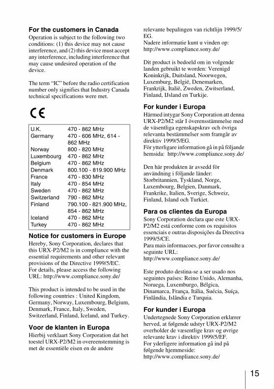
U.K. 470 - 862 MHzGermany 470 - 606 MHz, 614 -
862 MHzNorway 800 - 820 MHzLuxembourg 470 - 862 MHzBelgium 470 - 862 MHzDenmark 800.100 - 819.900 MHzFrance 470 - 830 MHzItaly 470 - 854 MHzSweden 470 - 862 MHzSwitzerland 790 - 862 MHzFinland 790.100 - 821.900 MHz,
854 - 862 MHzIceland 470 - 862 MHzTurkey 470 - 862 MHz
15
16
Dette produkt er beregnet til brug i de følgende lande: Storbritannien, Tyskland, Norge, Luxembourg, Belgien, Danmark, Frankrig, Italien, Sverige, Schweiz, Finland, Island og Tyrkiet.
Euroopassa oleville asiakkailleSony Corporation vakuuttaa täten että URX-P2/M2 tyyppinen laite on direktiivin 1999/5/EY oleellisten vaatimusten ja sitä koskevien direktiivin muiden ehtojen mukainen.Halutessasi lisätietoja, käy osoitteessa:http://www.compliance.sony.de/
Tämä tuote on tarkoitettu käytettäväksi seuraavissa maissa: Yhdistynyt kuningaskunta, Saksa, Norja, Luxemburg, Belgia, Tanska, Ranska, Italia, Ruotsi, Sveitsi, Suomi, Islanti ja Turkki.
For kundene i EuropaSony Corporation erklærer herved at utstyret URX-P2/M2 er i samsvar med de grunnleggende krav og øvrige relevante krav i direktiv 1999/5/EF. For flere detaljer, vennligst se: http://www.compliance.sony.de/
Dette produktet er ment for bruk i følgende land: Storbritannia, Tyskland, Norge, Luxemburg, Belgia, Danmark, Frankrike, Italia, Sverige, Sveits, Finland, Island og Tyrkia.
Για τ�υς πελάτες στην EυρώπηΜε την παρύσα η Sony Corporation δηλώνει �τι UTX-B2/H2/P1 συμμρφώνεται πρς της υσιώδεις απαιτήσεις και τις λιπές σ�ετικές διατά�εις της δηγίας 1999/5/ΕΚ..Για λεπτμέρειες παρακαλύμε �πως ελέν�ετε την ακ�λυθη σελίδα τυ διαδικτύυ:http://www.compliance.sony.de/
Τ πρϊ�ν πρρί%εται για �ρήση στις ε�ής �ώρες: Ηνωμέν Βασίλει, Γερμανία, Νρ)ηγία, Λυ�εμ)ύργ, Βέλγι, Δανία,
Γαλλία, Ιταλία, Συηδία, Ελ)ετία, Φινλανδία, Ισλανδία και Τυρκία.
Pro zákazníky v EvropěSony Corporation tímto prohlašuje, že tento URX-P2/M2 je ve shodě se základními požadavky a dalšími příslušnými ustanoveními směrnice 1999/5/ES.Podrobnosti lze získat na následující URL:http://www.compliance.sony.de/
Tento produkt je určen k použití v následujících zemích: Spojené království, Německo, Norsko, Lucembursko, Belgie, Dánsko, Francie, Itálie, Švédsko, Švýcarsko, Finsko, Island a Turecko.
Euroopa klientideleSony Corporation kinnitab käesolevaga seadme URX-P2/M2 vastavust 1999/5/EÜ direktiivi põhinõuetele ja nimetatud direktiivist tulenevatele teistele asjakohastele sätetele.Üksikasjalikum info: http://www.compliance.sony.de/.
See toode on ettenähtud kasutamiseks järgmistes riikides: Suurbritannia, Saksamaa, Norra, Luksemburg, Belgia,
Taani, Prantsusmaa, Itaalia, Rootsi, Šveits, Soome, Island ja Türgi.
Európai vásárlóink fi gyelmébeAlulírott, Sony Corporation nyilatkozom, hogy a(z) URX-P2/M2 megfelel a vonatkozó alapvető követelményeknek és az 1999/5/EC irányelv egyéb előírásainak.További információkat a következő weboldalon találhat:http://www.compliance.sony.de/
Ez a termék a következő országokban használható: Egyesült Királyság, Németország, Norvégia, Luxemburg, Belgium, Dánia, Franciaország, Olaszország, Svédország, Svájc, Finnország, Izland és Törökország.
Dotyczy klientów z EuropyNiniejszym Sony Corporation oświadcza, że URX-P2/M2 jest zgodne z zasadniczymi wymaganiami oraz innymistosownymi postanowieniami Dyrektywy 1999/5/WE.Szczegółowe informacje znaleźć można pod następującym adresem URL:http://www.compliance.sony.de/
Ten produkt jest przeznaczony do użytku w następujących krajach: Wielkiej Brytanii, Niemczech, Norwegii, Luksemburgu, Belgii, Danii, Francji, Włoszech, Szwecji, Szwajcarii, Finlandii, Islandii i Turcji.
Pentru clienţii din EuropaPrin prezenta, Sony Corporation declară că acest URX-P2/M2 respectă cerinţele esenţiale și este în conformitate cu prevederile Directivei 1995/5/EC.Pentru detalii, vă rugăm accesaţi următoarea adresă:http://www.compliance.sony.de/
Acest produs este destinat utilizării în următoarele ţări: Regatul Unit, Germania, Norvegia, Luxemburg, Belgia, Danemarca, Franţa, Italia, Suedia, Elveţia, Finlanda, Islanda și Turcia.
Pre zákazníkov v EurópeSony Corporation týmto vyhlasuje, že URX-P2/M2 spĺňa základné požiadavky a všetky príslušné ustanovenia Smernice 1999/5/ES.Podrobnosti získate na nasledovnej webovej adrese:http://www.compliance.sony.de/
Tento produkt je určený na používanie v nasledovných krajinách: Veľká Británia, Nemecko, Nórsko, Luxembursko, Belgicko, Dánsko, Francúzsko, Taliansko, Švédsko, Švajčiarsko, Fínsko, Island a Turecko.
17
18
Za stranke v EvropiSony Corporation izjavlja, da je ta URX-P2/M2 v skladu z bistvenimi zahtevami in ostalimi relevantnimi določili direktive 1999/5/ES.Za podrobnosti vas naprošamo, če pogledate naURL:http://www.compliance.sony.de/
Izdelek je namenjen za uporabo v naslednjih državah: Veliki Britaniji, Nemčiji, Norveški, Luksemburgu, Belgiji, Danski, Franciji, Italiji, Švedski, Švici, Finski, Islandiji in Turčiji.
WARNINGExcessive sound pressure from earphones and headphones can cause hearing loss.In order to use this product safely, avoid prolonged listening at excessive sound pressure levels.
Table of Contents
Configuration of the Packages ... 21UWP-V1 ................................ 21UWP-V2 ................................ 22UWP-V6 ................................ 23UWP-X7 ................................ 24UWP-X8 ................................ 25
Features ........................................ 26UWP-V1 ................................ 26UWP-V2 ................................ 26UWP-V6 ................................ 26UWP-X7 ................................ 27UWP-X8 ................................ 27
Parts Identification ...................... 28Body-pack transmitter (UTX-B2) ......................................... 28Hand-held microphone (UTX-H2) ......................................... 29Plug-on transmitter (UTX-P1) ......................................... 31Portable diversity tuner (URX-P2) ......................................... 32Diversity tuner module (URX-M2) ........................................ 34
Power Supply ............................... 35Inserting the batteries ............ 35
Attachment and Installation Procedures .................................... 37
Attaching the supplied accessories to the body-pack transmitter (UTX-B2) ............ 37Attaching the supplied accessory to the hand-held microphone (UTX-H2) .............................. 39Inserting the plug-on transmitter (UTX-P1) into the supplied soft case ........................................ 39Attaching the optional accessory
to the plug-on transmitter (UTX-P1) ..........................................39Attaching the supplied accessories to the portable diversity tuner (URX-P2) .......40Installing a diversity tuner module (URX-M2) ..............................41
Operation ......................................42Tuner Settings ..............................43
Setting the reception channel .43Searching the available channels within the group (Clear Channel Scan) .......................................45Selecting the channels on multiple tuners automatically ...............45Setting the monitor level ........46Resetting the accumulated use time indication ........................46
Transmitter Settings ....................47Setting the transmission channel ...................................47Setting the RF output power level ........................................48Setting the attenuation level of the audio input ..............................49Resetting the accumulated use time indication ........................49
System Configurations................. 50Configuration examples of the UWP-V1/V2/X7/X8 ...............50Configuration example of the UWP-V6 .................................53
Error Messages............................. 54Troubleshooting ........................... 55Important Notes on Use ...............58
On usage and storage .............58On cleaning ............................58
19Table of Contents
20
Specifications ............................... 59Transmitters (UTX-B2/H2/P1) ......................................... 59Tuners (URX-P2/M2) ............ 61
Table of Contents
Configuration of the Packages
This manual is for the UWP-V1/V2/V6/X7/X8 Wireless Microphone Packages. The contents of each package are described below.
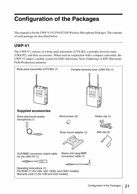
UWP-V1The UWP-V1 consists of a body-pack transmitter (UTX-B2), a portable diversity tuner (URX-P2), and their accessories. When used in conjunction with a compact camcorder, the UWP-V1 makes a mobile system for ENG (Electronic News Gathering) or EFP (Electronic Field Production) purposes.
Body-pack transmitter (UTX-B2) (1) Portable diversity tuner (URX-P2) (1)
Supplied accessories
Omni-directional lavalier microphone (1)
Shoe mount adapter (1)
Operating Instructions (1)CD-ROM (1) (for U30, U42, CE62, and CE67 models)Warranty card (1) (for U30 and U42 models)
Belt clip (2)
Wind screen (3) Holder clip (1)
Stereo mini plug-BMP conversion cable (1)
XLR-BMP conversion output cable for the URX-P2 (1)
21Configuration of the Packages
22
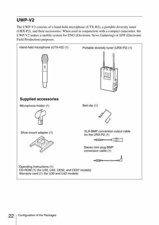
UWP-V2The UWP-V2 consists of a hand-held microphone (UTX-H2), a portable diversity tuner (URX-P2), and their accessories. When used in conjunction with a compact camcorder, the UWP-V2 makes a mobile system for ENG (Electronic News Gathering) or EFP (Electronic Field Production) purposes.
Hand-held microphone (UTX-H2) (1) Portable diversity tuner (URX-P2) (1)
Supplied accessories
Microphone holder (1)
Shoe mount adapter (1)
Operating Instructions (1)CD-ROM (1) (for U30, U42, CE62, and CE67 models)Warranty card (1) (for U30 and U42 models)
Belt clip (1)
Stereo mini plug-BMP conversion cable (1)
XLR-BMP conversion output cable for the URX-P2 (1)
Configuration of the Packages
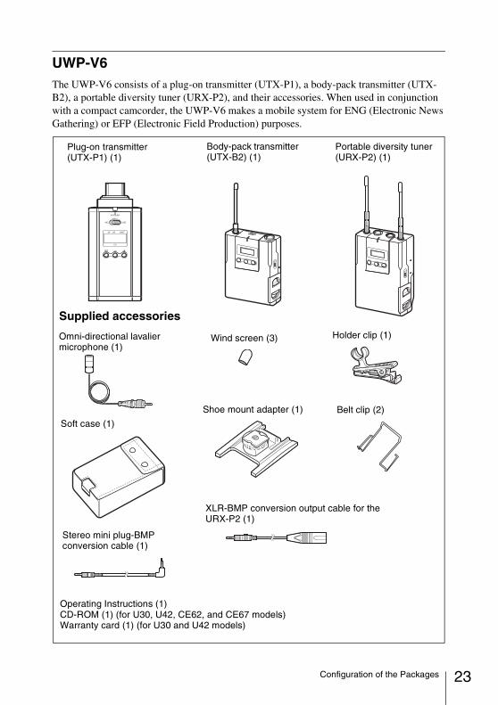
UWP-V6The UWP-V6 consists of a plug-on transmitter (UTX-P1), a body-pack transmitter (UTX-B2), a portable diversity tuner (URX-P2), and their accessories. When used in conjunction with a compact camcorder, the UWP-V6 makes a mobile system for ENG (Electronic News Gathering) or EFP (Electronic Field Production) purposes.
Body-pack transmitter (UTX-B2) (1)
Portable diversity tuner (URX-P2) (1)
Supplied accessories
Soft case (1)
Plug-on transmitter (UTX-P1) (1)
Shoe mount adapter (1) Belt clip (2)
Wind screen (3) Holder clip (1)
Stereo mini plug-BMP conversion cable (1)
Operating Instructions (1)CD-ROM (1) (for U30, U42, CE62, and CE67 models)Warranty card (1) (for U30 and U42 models)
XLR-BMP conversion output cable for the URX-P2 (1)
Omni-directional lavalier microphone (1)
23Configuration of the Packages
24
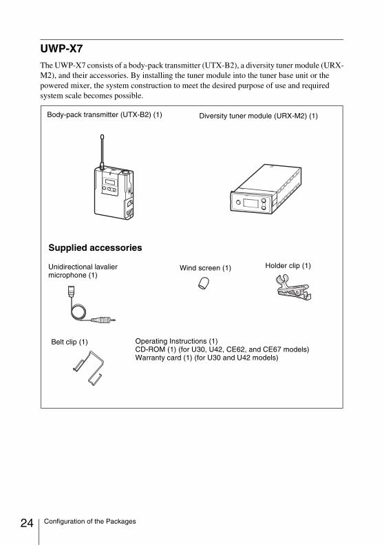
UWP-X7The UWP-X7 consists of a body-pack transmitter (UTX-B2), a diversity tuner module (URX-M2), and their accessories. By installing the tuner module into the tuner base unit or the powered mixer, the system construction to meet the desired purpose of use and required system scale becomes possible.
Body-pack transmitter (UTX-B2) (1) Diversity tuner module (URX-M2) (1)
Supplied accessories
Unidirectional lavalier microphone (1)
Wind screen (1) Holder clip (1)
Belt clip (1) Operating Instructions (1)CD-ROM (1) (for U30, U42, CE62, and CE67 models)Warranty card (1) (for U30 and U42 models)
Configuration of the Packages
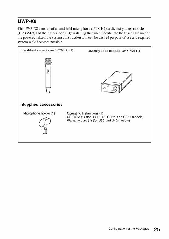
UWP-X8The UWP-X8 consists of a hand-held microphone (UTX-H2), a diversity tuner module (URX-M2), and their accessories. By installing the tuner module into the tuner base unit or the powered mixer, the system construction to meet the desired purpose of use and required system scale becomes possible.
Diversity tuner module (URX-M2) (1)
Supplied accessories
Operating Instructions (1)CD-ROM (1) (for U30, U42, CE62, and CE67 models)Warranty card (1) (for U30 and U42 models)
Hand-held microphone (UTX-H2) (1)
Microphone holder (1)
25Configuration of the Packages
26
Features
Each of the UWP-V1/V2/V6/X7/X8 wireless microphone packages (referred to as the UWP series packages hereafter) combines a transmitter (body-pack transmitter (UTX-B2) or hand-held microphone (UTX-H2)) and a receiver (portable diversity tuner (URX-P2) or diversity tuner module (URX-M2)). (An additional transmitter (plug-on transmitter (UTX-P1) is provided for the UWP-V6 only.) The UWP series packages can be used with a compact camcorder for ENG (Electronic News Gathering) purposes, and with a powered mixer for AV presentations or as a PA (public address) system.
The UWP series packages are not compatible with the WRT series transmitters, WRR series tuners, or WRU series tuner units.
The featured components of the package are described below.
UWP-V1
Body-pack transmitter (UTX-B2)This is a small and lightweight transmitter with a crystal-controlled PLL (phase lock loop) synthesized system and a BMP-type microphone input connector. The RF power output can be set at 30 mW or at 5 mW. The MIC/LINE input selector is equipped to accept wide range of input signals.
Portable diversity tuner (URX-P2)This tuner employs a space diversity system with little signal dropout and two angle-adjustable antennas. It comes with an adapter for mounting the tuner on the compact camcorder (PMW-EX1, HDR-Z7, etc.). The Clear Channel Scan function is also provided to search available channels with easy operation.
UWP-V2
Hand-held microphone (UTX-H2)This microphone is equipped with a built-in antenna and a unidirectional dynamic microphone unit. The RF power output can be set at 30 mW or at 5 mW.
Portable diversity tuner (URX-P2)This tuner employs a space diversity system with little signal dropout and two angle-adjustable antennas. It comes with an adapter for mounting the tuner on the compact camcorder (PMW-EX1, HDR-Z7, etc.). The Clear Channel Scan function is also provided to search available channels with easy operation.
UWP-V6
Plug-on transmitter (UTX-P1)This is a small and lightweight plug-on transmitter with a crystal-controlled PLL (phase lock loop) synthesized system and an XLR-type microphone input connector. The RF power output is set at 50 mW.
Note
Features
Body-pack transmitter (UTX-B2)This is a small and lightweight transmitter with a crystal-controlled PLL (phase lock loop) synthesized system and a BMP-type microphone input connector. The RF power output can be set at 30 mW or at 5 mW. The MIC/LINE input selector is equipped to accept wide range of input signals.
Portable diversity tuner (URX-P2)This tuner employs a space diversity system with little signal dropout and two angle-adjustable antennas. It comes with an adapter for mounting the tuner on the compact camcorder (PMW-EX1, HDR-Z7, etc.). The Clear Channel Scan function is also provided to search available channels with easy operation.
UWP-X7
Body-pack transmitter (UTX-B2)This is a small and lightweight transmitter with a crystal-controlled PLL (phase lock loop) synthesized system and a BMP-type microphone input connector. The RF power output can be set at 30 mW or at 5 mW. The MIC/LINE input selector is equipped to accept wide range of input signals.
Diversity tuner module (URX-M2)This tuner module can be incorporated into the MB-X6 Tuner Base Unit or SRP-X500P Powered Mixer.
UWP-X8
Hand-held microphone (UTX-H2)This microphone is equipped with a built-in antenna and a unidirectional dynamic microphone unit. The RF power output can be set at 30 mW or at 5 mW.
Diversity tuner module (URX-M2)This tuner module can be incorporated into the MB-X6 Tuner Base Unit or SRP-X500P Powered Mixer.
27Features
28
Parts Identification
Body-pack transmitter (UTX-B2)
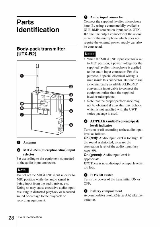
a Antenna
b MIC/LINE (microphone/line) input selector
Set according to the equipment connected to the audio input connector.
Do not set the MIC/LINE input selector to MIC position while the audio signal is being input from the audio mixer, etc. Doing so may cause excessive audio input, resulting in distorted playback or recorded sound or damage to the playback or recording equipment.
c Audio input connectorConnect the supplied lavalier microphone here. By using a commercially available XLR-BMP conversion input cable, UTX-B2, the line output connector of the audio mixer or the microphone which does not require the external power supply can also be connected.
• When the MIC/LINE input selector is set to MIC position, a power voltage for the supplied lavalier microphone is applied to the audio input connector. For this purpose, a special electrical wiring is used inside this connector. Be sure to use a commercially available XLR-BMP conversion input cable to connect the equipment other than the supplied lavalier microphone.
• Note that the proper performance may not be obtained if a lavalier microphone which is not supplied with the UWP series package is used.
d AF/PEAK (audio frequency/peak level) indicator
Turns on or off according to the audio input level as follows.On (red): Audio input level is too high. If the sound is distorted, increase the attenuation level of the audio input (see page 49).On (green): Audio input level is appropriate.Off: There is no audio input or input level is too low.
e POWER switchTurns the power of the transmitter ON or OFF.
f Battery compartmentAccommodates two LR6 (size AA) alkaline batteries.
Note
Notes
Parts Identification
For details on how to insert the batteries, see “Power Supply” on page 35.
g + (+ selection) / – (– selection/reset) buttons
Press these buttons to set the transmission channel, frequency, or attenuation level of the input signal.The “–” button resets the accumulated use time to “00:00”.
h SET buttonPress to change and enter display parameters.
For details, see “Transmitter Settings” on page 47.
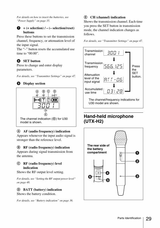
i Display section
A AF (audio frequency) indicationAppears whenever the input audio signal is stronger than the reference level.
B RF (radio frequency) indicationAppears during signal transmission from the antenna.
C RF (radio frequency) level indication
Shows the RF output level setting.
For details, see “Setting the RF output power level” on page 48.
D BATT (battery) indicationShows the battery condition.
For details, see “Battery indication” on page 36.
E CH (channel) indicationShows the transmission channel. Each time you press the SET button in transmission mode, the channel indication changes as follows.
For details, see “Transmitter Settings” on page 47.
Hand-held microphone (UTX-H2)
The channel indication (E) for U30 model is shown.
Transmission channel
Transmission frequency
Accumulated use time
Attenuation level of the input signal
The channel/frequency indications for U30 model are shown.
Press the SET button.
The rear side of the battery compartment
29Parts Identification
30
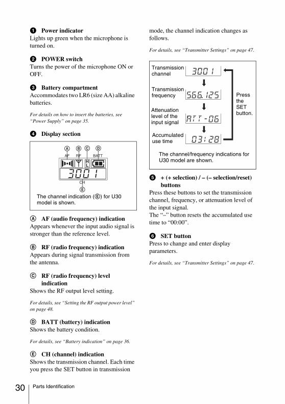
a Power indicatorLights up green when the microphone is turned on.
b POWER switchTurns the power of the microphone ON or OFF.
c Battery compartmentAccommodates two LR6 (size AA) alkaline batteries.
For details on how to insert the batteries, see “Power Supply” on page 35.
d Display section
A AF (audio frequency) indicationAppears whenever the input audio signal is stronger than the reference level.
B RF (radio frequency) indicationAppears during signal transmission from the antenna.
C RF (radio frequency) level indication
Shows the RF output level setting.
For details, see “Setting the RF output power level” on page 48.
D BATT (battery) indicationShows the battery condition.
For details, see “Battery indication” on page 36.
E CH (channel) indicationShows the transmission channel. Each time you press the SET button in transmission
mode, the channel indication changes as follows.
For details, see “Transmitter Settings” on page 47.
e + (+ selection) / – (– selection/reset) buttons
Press these buttons to set the transmission channel, frequency, or attenuation level of the input signal.The “–” button resets the accumulated use time to “00:00”.
f SET buttonPress to change and enter display parameters.
For details, see “Transmitter Settings” on page 47.
The channel indication (E) for U30 model is shown.
Transmission channel
Transmission frequency
Accumulated use time
Attenuation level of the input signal
The channel/frequency indications for U30 model are shown.
Press the SET button.
Parts Identification
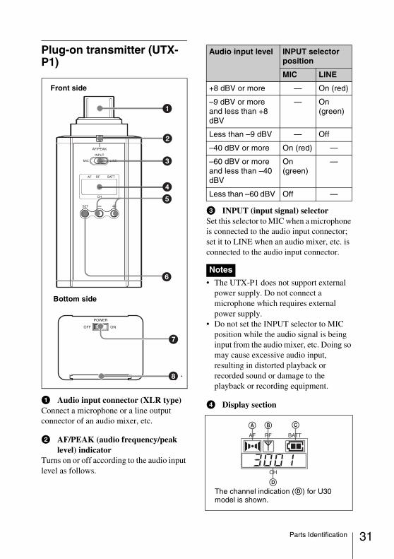
Plug-on transmitter (UTX-P1)
a Audio input connector (XLR type)Connect a microphone or a line output connector of an audio mixer, etc.
b AF/PEAK (audio frequency/peak level) indicator
Turns on or off according to the audio input level as follows.
c INPUT (input signal) selectorSet this selector to MIC when a microphone is connected to the audio input connector; set it to LINE when an audio mixer, etc. is connected to the audio input connector.
• The UTX-P1 does not support external power supply. Do not connect a microphone which requires external power supply.
• Do not set the INPUT selector to MIC position while the audio signal is being input from the audio mixer, etc. Doing so may cause excessive audio input, resulting in distorted playback or recorded sound or damage to the playback or recording equipment.
d Display section
Front side
Bottom side
Audio input level INPUT selector position
MIC LINE
+8 dBV or more — On (red)
–9 dBV or more and less than +8 dBV
— On (green)
Less than –9 dBV — Off
–40 dBV or more On (red) —
–60 dBV or more and less than –40 dBV
On (green)
—
Less than –60 dBV Off —
Notes
The channel indication (D) for U30 model is shown.
31Parts Identification
32
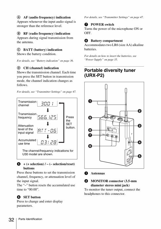
A AF (audio frequency) indicationAppears whenever the input audio signal is stronger than the reference level.
B RF (radio frequency) indicationAppears during signal transmission from the antenna.
C BATT (battery) indicationShows the battery condition.
For details, see “Battery indication” on page 36.
D CH (channel) indicationShows the transmission channel. Each time you press the SET button in transmission mode, the channel indication changes as follows.
For details, see “Transmitter Settings” on page 47.
e + (+ selection) / – (– selection/reset) buttons
Press these buttons to set the transmission channel, frequency, or attenuation level of the input signal.The “–” button resets the accumulated use time to “00:00”.
f SET buttonPress to change and enter display parameters.
For details, see “Transmitter Settings” on page 47.
g POWER switchTurns the power of the microphone ON or OFF.
h Battery compartmentAccommodates two LR6 (size AA) alkaline batteries.
For details on how to insert the batteries, see “Power Supply” on page 35.
Portable diversity tuner (URX-P2)
a Antennas
b MONITOR connector (3.5-mm diameter stereo mini jack)
To monitor the tuner output, connect the headphones to this connector.
Transmission channel
Transmission frequency
Accumulated use time
Attenuation level of the input signal
The channel/frequency indications for U30 model are shown.
Press the SET button.
Parts Identification
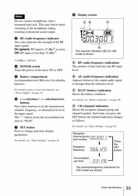
Do not connect headphones with a monaural mini jack. This may lead to short-circuiting of the headphone output, resulting in distorted sound output.
c RF (radio frequency) indicatorThe color indicates the strength of the RF input signal.On (green): RF input is 15 dBµ1) or more.Off: RF input is less than 15 dBµ1).
1) 0 dBµ = 1 µVEMF
d POWER switchTurns the power of the tuner ON or OFF.
e Battery compartmentAccommodates two LR6 (size AA) alkaline batteries.
For details on how to insert the batteries, see “Power Supply” on page 35.
f + (+ selection) / – (– selection/reset) buttons
Press these buttons to set the transmission channel, frequency, or attenuation level of the input signal.The “–” button resets the accumulated use time to “00:00”.
g SET buttonPress to change and enter display parameters.
For details, see “Tuner Settings” on page 43.
h Display section
A RF (radio frequency) indicationsThe number of dots indicates the RF input level.
B AF (audio frequency) indicationAppears whenever the output audio signal is stronger than the reference level.
C BATT (battery) indicationShows the battery condition.
For details, see “Battery indication” on page 36.
D CH (channel) indicationShows the reception channel group and channel number. Each time you press the SET button, the channel indication changes as follows.
For details, see“Tuner Settings” on page 43.
Note
The channel indication (C) for U30 model is shown.
Reception channel group and number
Reception frequency
The channel/frequency indications for U30 model are shown.
Press the SET button.
Accumulated use time
33Parts Identification
34
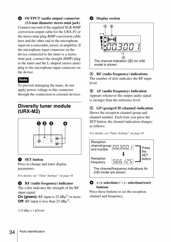
i OUTPUT (audio output) connector (3.5-mm diameter stereo mini jack)
Connect one end of the supplied XLR-BMP conversion output cable for the URX-P2 or the stereo mini plug-BMP conversion cable here and the other end to the microphone input on a camcorder, mixer, or amplifier. If the microphone input connector on the device connected to the tuner is a stereo mini jack, connect the straight (BMP) plug to the tuner and the L-shaped (stereo mini) plug to the microphone input connector on the device.
To prevent damaging the tuner, do not apply power voltage to this connector through the connection to external devices.
Diversity tuner module (URX-M2)
a SET buttonPress to change and enter display parameters.
For details, see “Tuner Settings” on page 43.
b RF (radio frequency) indicatorThe color indicates the strength of the RF input signal.On (green): RF input is 25 dBµ1) or more.Off: RF input is less than 25 dBµ1).
1) 0 dBµ = 1 µVEMF
c Display section
A RF (radio frequency) indicationsThe number of dots indicates the RF input level.
B AF (audio frequency) indicationAppears whenever the output audio signal is stronger than the reference level.
C GP (group)/CH (channel) indicationShows the reception channel group and channel number. Each time you press the SET button, the channel indication changes as follows.
For details, see“Tuner Settings” on page 43.
d + (+ selection) / – (– selection/reset) buttons
Press these buttons to set the reception channel and frequency.
Note
The channel indication (C) for U30 model is shown.
Reception channel group and number
Reception frequency
The channel/frequency indications for U30 model are shown.
Press the SET button.
Parts Identification
Power Supply
This section explains the power supply for each component.
Diversity tuner module (URX-M2)When incorporated into another component (e.g., MB-X6, SRP-X500P, etc.), the tuner module draws its power from that component.
For details on the power supply to the diversity tuner module, refer to the operating instructions of the component in which the diversity tuner module is installed.
Body-pack transmitter (UTX-B2), hand-held microphone (UTX-H2), plug-on transmitter (UTX-P1), and portable diversity tuner (URX-P2)These components can be powered by two LR6 (size AA) alkaline batteries. Details on inserting the batteries and the battery condition indication are given below:
The manganese batteries cannot draw sufficient performance from the component. Be sure to use the alkaline batteries.
Inserting the batteries
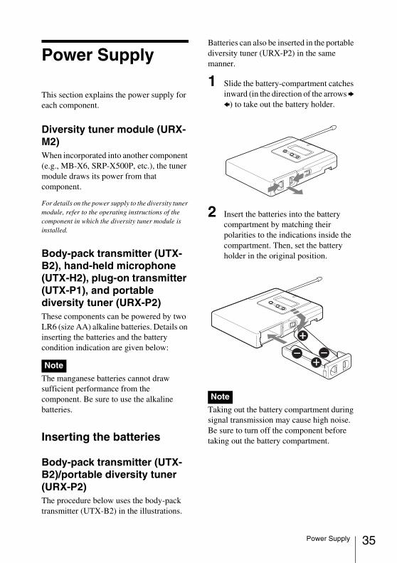
Body-pack transmitter (UTX-B2)/portable diversity tuner (URX-P2)The procedure below uses the body-pack transmitter (UTX-B2) in the illustrations.
Batteries can also be inserted in the portable diversity tuner (URX-P2) in the same manner.
1 Slide the battery-compartment catches inward (in the direction of the arrows b B) to take out the battery holder.
2 Insert the batteries into the battery compartment by matching their polarities to the indications inside the compartment. Then, set the battery holder in the original position.
Taking out the battery compartment during signal transmission may cause high noise. Be sure to turn off the component before taking out the battery compartment.
Note
Note
35Power Supply
36
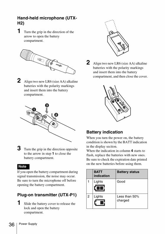
Hand-held microphone (UTX-H2)
1 Turn the grip in the direction of the arrow to open the battery compartment.
2 Align two new LR6 (size AA) alkaline batteries with the polarity markings and insert them into the battery compartment.
3 Turn the grip in the direction opposite to the arrow in step 1 to close the battery compartment.
If you open the battery compartment during signal transmission, the noise may occur. Be sure to turn the microphone off before opening the battery compartment.
Plug-on transmitter (UTX-P1)
1 Slide the battery cover to release the lock and open the battery compartment.
2 Align two new LR6 (size AA) alkaline batteries with the polarity markings and insert them into the battery compartment, and then close the cover.
Battery indicationWhen you turn the power on, the battery condition is shown by the BATT indication in the display section.When the indication in column 4 starts to flash, replace the batteries with new ones. Be sure to check the expiration date printed on the new batteries before using them.
Note
BATT indication
Battery status
1 Lights
Good
2 Lights
Less than 50% charged
Power Supply
The indicated battery condition may not be correct if the batteries were not new when installed. If you plan to use the component for a long period, it is recommended that you replace the batteries with brand new ones.
Notes on batteryBatteries may leak or explode if mistreated. Be sure to follow these instructions.• Be sure to install the batteries with the
correct polarity.• Always replace the two batteries
together.• Do not use different types of batteries or
old and new one together.• The batteries are not rechargeable.• When not using the component for a long
period of time, remove the batteries to avoid leakage. If the batteries do leak, clean all leakage from the battery compartment and the component. Leakage left in the compartment and the component may cause poor battery contact. If there seems to be poor battery contact, consult your Sony dealer.
Attachment and Installation Procedures
This section describes the procedures for attaching the supplied accessories to the components and the installation of the diversity tuner module (URX-M2) into the MB-X6 Tuner Base Unit or SRP-X500P Powered Mixer.
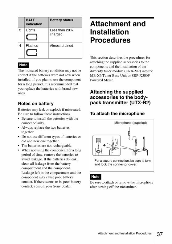
Attaching the supplied accessories to the body-pack transmitter (UTX-B2)
To attach the microphone
Be sure to attach or remove the microphone after turning off the transmitter.
3 Lights
Less than 20% charged
4 Flashes Almost drained
Note
BATT indication
Battery status
Note
Microphone (supplied)
For a secure connection, be sure to turn and lock the connector cover.
37Attachment and Installation Procedures
38
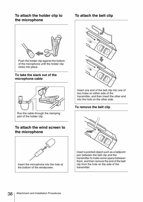
To attach the holder clip to the microphone
To take the slack out of the microphone cable
To attach the wind screen to the microphone
To attach the belt clip
To remove the belt clip
Push the holder clip against the bottom of the microphone until the holder clip clicks into place.
Run the cable through the clamping part of the holder clip.
Insert the microphone into the hole at the bottom of the windscreen.
Insert one end of the belt clip into one of two holes on either side of the transmitter, and then insert the other end into the hole on the other side.
Insert a pointed object such as a ballpoint pen between the belt clip and the transmitter to make some space between them, and then remove the end of the belt clip from the hole on the side of the transmitter.
Attachment and Installation Procedures
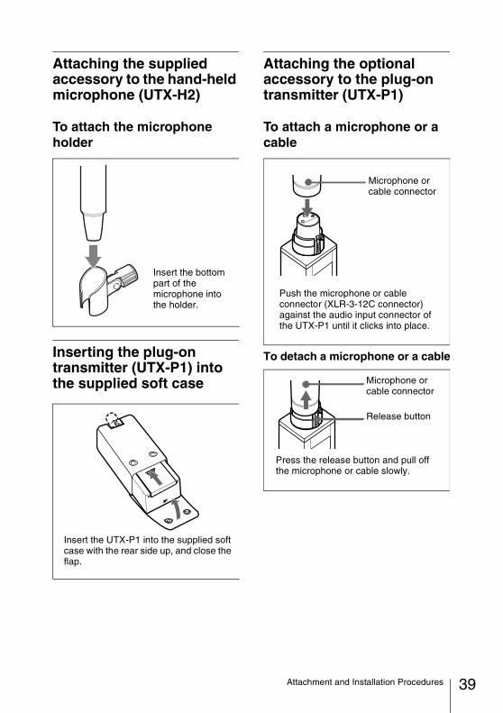
Attaching the supplied accessory to the hand-held microphone (UTX-H2)
To attach the microphone holder
Inserting the plug-on transmitter (UTX-P1) into the supplied soft case
Attaching the optional accessory to the plug-on transmitter (UTX-P1)
To attach a microphone or a cable
To detach a microphone or a cable
Insert the bottom part of the microphone into the holder.
Insert the UTX-P1 into the supplied soft case with the rear side up, and close the flap.
Push the microphone or cable connector (XLR-3-12C connector) against the audio input connector of the UTX-P1 until it clicks into place.
Microphone or cable connector
Press the release button and pull off the microphone or cable slowly.
Release button
Microphone or cable connector
39Attachment and Installation Procedures
40
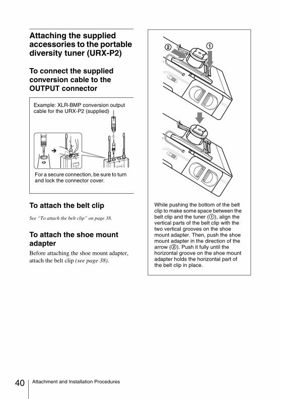
Attaching the supplied accessories to the portable diversity tuner (URX-P2)
To connect the supplied conversion cable to the OUTPUT connector
To attach the belt clip
See “To attach the belt clip” on page 38.
To attach the shoe mount adapterBefore attaching the shoe mount adapter, attach the belt clip (see page 38).
Example: XLR-BMP conversion output cable for the URX-P2 (supplied)
For a secure connection, be sure to turn and lock the connector cover.
While pushing the bottom of the belt clip to make some space between the belt clip and the tuner (1), align the vertical parts of the belt clip with the two vertical grooves on the shoe mount adapter. Then, push the shoe mount adapter in the direction of the arrow (2). Push it fully until the horizontal groove on the shoe mount adapter holds the horizontal part of the belt clip in place.
Attachment and Installation Procedures
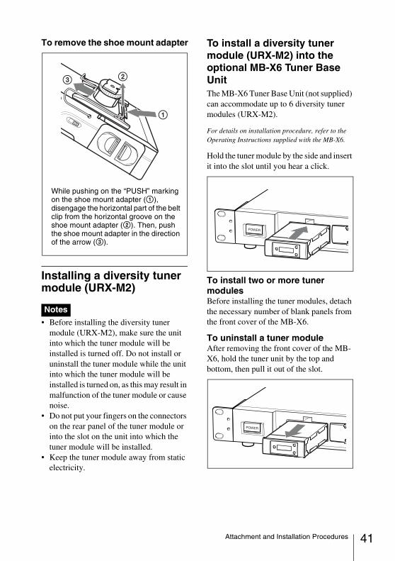
To remove the shoe mount adapter
Installing a diversity tuner module (URX-M2)
• Before installing the diversity tuner module (URX-M2), make sure the unit into which the tuner module will be installed is turned off. Do not install or uninstall the tuner module while the unit into which the tuner module will be installed is turned on, as this may result in malfunction of the tuner module or cause noise.
• Do not put your fingers on the connectors on the rear panel of the tuner module or into the slot on the unit into which the tuner module will be installed.
• Keep the tuner module away from static electricity.
To install a diversity tuner module (URX-M2) into the optional MB-X6 Tuner Base UnitThe MB-X6 Tuner Base Unit (not supplied) can accommodate up to 6 diversity tuner modules (URX-M2).
For details on installation procedure, refer to the Operating Instructions supplied with the MB-X6.
Hold the tuner module by the side and insert it into the slot until you hear a click.
To install two or more tuner modulesBefore installing the tuner modules, detach the necessary number of blank panels from the front cover of the MB-X6.
To uninstall a tuner moduleAfter removing the front cover of the MB-X6, hold the tuner unit by the top and bottom, then pull it out of the slot.
Notes
While pushing on the “PUSH” marking on the shoe mount adapter (1), disengage the horizontal part of the belt clip from the horizontal groove on the shoe mount adapter (2). Then, push the shoe mount adapter in the direction of the arrow (3).
41Attachment and Installation Procedures
42
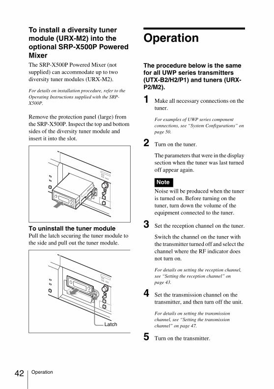
To install a diversity tuner module (URX-M2) into the optional SRP-X500P Powered MixerThe SRP-X500P Powered Mixer (not supplied) can accommodate up to two diversity tuner modules (URX-M2).
For details on installation procedure, refer to the Operating Instructions supplied with the SRP-X500P.
Remove the protection panel (large) from the SRP-X500P. Inspect the top and bottom sides of the diversity tuner module and insert it into the slot.
To uninstall the tuner modulePull the latch securing the tuner module to the side and pull out the tuner module.
Operation
The procedure below is the same for all UWP series transmitters (UTX-B2/H2/P1) and tuners (URX-P2/M2).
1 Make all necessary connections on the tuner.
For examples of UWP series component connections, see “System Configurations” on page 50.
2 Turn on the tuner.
The parameters that were in the display section when the tuner was last turned off appear again.
Noise will be produced when the tuner is turned on. Before turning on the tuner, turn down the volume of the equipment connected to the tuner.
3 Set the reception channel on the tuner.
Switch the channel on the tuner with the transmitter turned off and select the channel where the RF indicator does not turn on.
For details on setting the reception channel, see “Setting the reception channel” on page 43.
4 Set the transmission channel on the transmitter, and then turn off the unit.
For details on setting the transmission channel, see “Setting the transmission channel” on page 47.
5 Turn on the transmitter.
Latch
Note
Operation
If noise is heardDepending on the environment where the UWP series components are installed, external noise or radio waves may disrupt transmission on certain channels.When selecting a channel under these circumstances, turn off the transmitter.Then, on the tuner, select a channel for which the RF indicator does not light up (i.e., a channel free from noise or radio wave interference). Set the same channel on the transmitter.
To prevent interference or noise, please take the following precautions.• Do not use two or more transmitters with
the same wireless channels.• When operating two or more UWP series
packages simultaneously, set each package to a different channel within the same channel group.
• Keep the reception antenna and the transmitter separated more than 3 meters (9 feet 11 inches).
• When operating two or more UWP series packages simultaneously with different channel groups, make sure that they are at least 100 meters (330 feet) apart, if they are used within clear sight of each other. (The actual distance may differ depending on the circumstances.)
Tuner Settings
Setting the reception channelThe procedure below is the same for all UWP series tuners (URX-P2/M2).
Refer to the pdf files “Sony Wireless Microphone System Frequency List” on the supplied CD-ROM for details on the selectable channel groups and channels (for U30, U42, CE62, and CE67 models).
1 Press down the SET button for more than one second.
Keep pressing the SET button until the display section parameters start to flash.
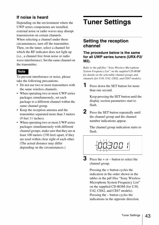
2 Press the SET button repeatedly until the channel group and the channel number indications appear.
The channel group indication starts to flash.
3 Press the + or – button to select the channel group.
Pressing the + button cycles the indication in the order shown in the tables in the pdf files “Sony Wireless Microphone System Frequency List” on the supplied CD-ROM (for U30, U42, CE62, and CE67 models).Pressing the – button cycles the indications in the opposite direction.
Note
43Tuner Settings
44
Hold down the + or – button to change the channel group faster.
4 When the desired channel group number appears, press the SET button.
The selected group is entered.The right four digits start to flash to allow the selection of the channel number.
5 Press the + or – button to select the channel number.
The channel indication changes in the order shown in the tables in the pdf files “Sony Wireless Microphone System Frequency List” on the supplied CD-ROM (for U30, U42, CE62, and CE67 models).
6 When the desired channel number appears, leave the tuner for about 10 seconds or press down the SET button for more than one second.
The selected channel number stops flashing and the selection is stored in memory.
To select the channel by frequency indication
1 Press the SET button for more than one second.
Keep pressing the SET button until the display section parameters start to flash.
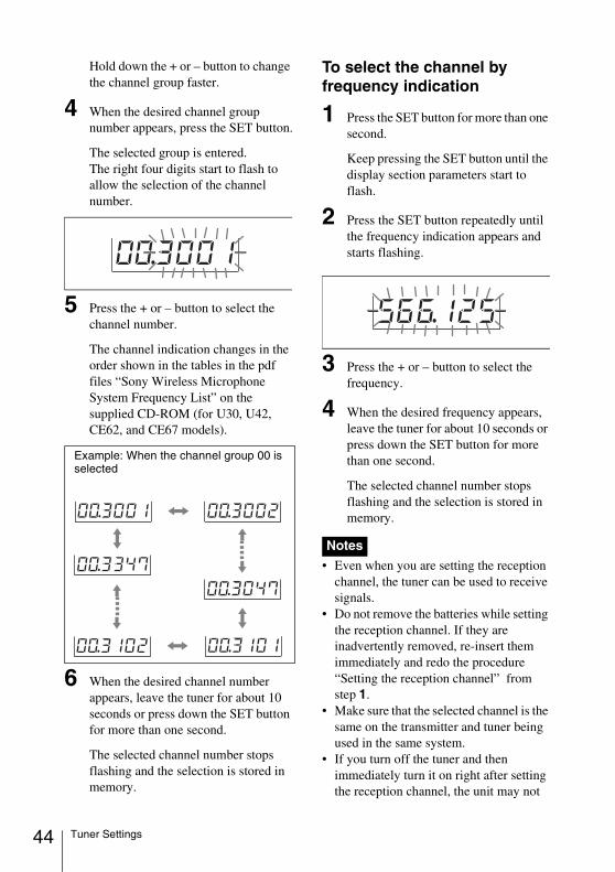
2 Press the SET button repeatedly until the frequency indication appears and starts flashing.
3 Press the + or – button to select the frequency.
4 When the desired frequency appears, leave the tuner for about 10 seconds or press down the SET button for more than one second.
The selected channel number stops flashing and the selection is stored in memory.
• Even when you are setting the reception channel, the tuner can be used to receive signals.
• Do not remove the batteries while setting the reception channel. If they are inadvertently removed, re-insert them immediately and redo the procedure “Setting the reception channel” from step 1.
• Make sure that the selected channel is the same on the transmitter and tuner being used in the same system.
• If you turn off the tuner and then immediately turn it on right after setting the reception channel, the unit may not
Example: When the channel group 00 is selected
Notes
Tuner Settings
operate normally. Wait a few seconds before turning it on again.
Searching the available channels within the group (Clear Channel Scan)The procedure below can be performed with the portable diversity tuner (URX-P2) only.
Available channels within the specified channel group can be searched.Before performing this procedure, select the channel group.
For details on channel group selection, see “Setting the reception channel” on page 43.
1 While pressing down the SET button, press the + button.
Keep both buttons pressed down.
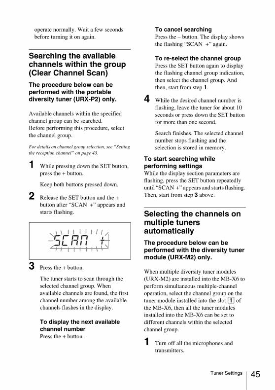
2 Release the SET button and the + button after “SCAN +” appears and starts flashing.
3 Press the + button.
The tuner starts to scan through the selected channel group. When available channels are found, the first channel number among the available channels flashes in the display.
To display the next available channel numberPress the + button.
To cancel searchingPress the – button. The display shows the flashing “SCAN +” again.
To re-select the channel groupPress the SET button again to display the flashing channel group indication, then select the channel group. And then, start from step 1.
4 While the desired channel number is flashing, leave the tuner for about 10 seconds or press down the SET button for more than one second.
Search finishes. The selected channel number stops flashing and the selection is stored in memory.
To start searching while performing settingsWhile the display section parameters are flashing, press the SET button repeatedly until “SCAN +” appears and starts flashing. Then, start from step 3 above.
Selecting the channels on multiple tuners automaticallyThe procedure below can be performed with the diversity tuner module (URX-M2) only.
When multiple diversity tuner modules (URX-M2) are installed into the MB-X6 to perform simultaneous multiple-channel operation, select the channel group on the tuner module installed into the slot 1 of the MB-X6, then all the tuner modules installed into the MB-X6 can be set to different channels within the selected channel group.
1 Turn off all the microphones and transmitters.
45Tuner Settings
46
2 Select the channel group on the tuner module installed into the slot 1 of the MB-X6.
3 After confirming that the channel group indication has stopped flashing (about 10 seconds after you have selected the channel group), keep pressing the + button on the tuner module installed into the slot 1 of the MB-X6.
All the tuner modules installed into the MB-X6 are set to the available channels within the selected channel group.After the automatic detection and selection of available channels finish, you can change the group and channel on each tuner module manually.
• Do the automatic detection and selection of available channels with the channel group other than channel group 00.
• When there are unavailable channels due to extraneous radio wave and the channel could not be selected on some tuner modules, “NO CH” appears on the display of those tuner modules. If this happens, select the channel group with no interference from extraneous radio wave, and repeat the procedure above.
Setting the monitor levelThe procedure below can be performed with the portable diversity tuner (URX-P2) only.
You can set the monitor level for monitoring the tuner output within the range of 01 to 24.
1 While the parameters on the display section are not flashing, press the + or – button once.
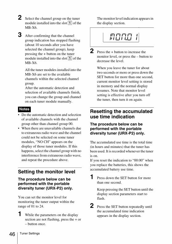
The monitor level indication appears in the display section.
2 Press the + button to increase the monitor level, or press the – button to decrease the level.
When you leave the tuner for about two seconds or more or press down the SET button for more than one second, current monitor level setting is stored in memory and the normal display resumes. Note that monitor level setting is effective after you turn off the tuner, then turn it on again.
Resetting the accumulated use time indicationThe procedure below can be performed with the portable diversity tuner (URX-P2) only.
The accumulated use time is the total time (in hours and minutes) that the tuner has been used. It is recorded whenever the tuner is on.If you reset the indication to “00:00” when you replace the batteries, this shows the accumulated battery use time.
1 Press down the SET button for more than one second.
Keep pressing the SET button until the display section parameters start to flash.
2 Press the SET button repeatedly until the accumulated time indication appears in the display section.
Notes
Tuner Settings
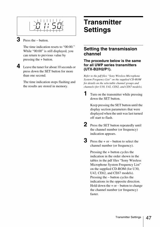
3 Press the – button.
The time indication resets to “00:00.”While “00:00” is still displayed, you can return to previous value by pressing the + button.
4 Leave the tuner for about 10 seconds or press down the SET button for more than one second.
The time indication stops flashing and the results are stored in memory.
Transmitter Settings
Setting the transmission channelThe procedure below is the same for all UWP series transmitters (UTX-B2/H2/P1).
Refer to the pdf files “Sony Wireless Microphone System Frequency List” on the supplied CD-ROM for details on the selectable channel groups and channels (for U30, U42, CE62, and CE67 models).
1 Turn on the transmitter while pressing down the SET button.
Keep pressing the SET button until the display section parameters that were displayed when the unit was last turned off start to flash.
2 Press the SET button repeatedly until the channel number (or frequency) indication appears.
3 Press the + or – button to select the channel number (or frequency).
Pressing the + button cycles the indication in the order shown in the tables in the pdf files “Sony Wireless Microphone System Frequency List” on the supplied CD-ROM (for U30, U42, CE62, and CE67 models).Pressing the – button cycles the indications in the opposite direction.Hold down the + or – button to change the channel number (or frequency) faster.
47Transmitter Settings
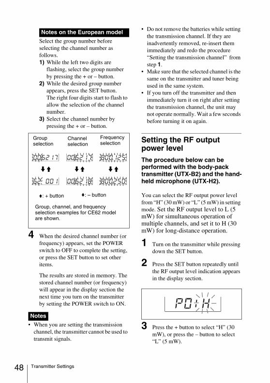
48
Select the group number before selecting the channel number as follows.1) While the left two digits are
flashing, select the group number by pressing the + or – button.
2) While the desired group number appears, press the SET button.The right four digits start to flash to allow the selection of the channel number.
3) Select the channel number by pressing the + or – button.
4 When the desired channel number (or frequency) appears, set the POWER switch to OFF to complete the setting, or press the SET button to set other items.
The results are stored in memory. The stored channel number (or frequency) will appear in the display section the next time you turn on the transmitter by setting the POWER switch to ON.
• When you are setting the transmission channel, the transmitter cannot be used to transmit signals.
• Do not remove the batteries while setting the transmission channel. If they are inadvertently removed, re-insert them immediately and redo the procedure “Setting the transmission channel” from step 1.
• Make sure that the selected channel is the same on the transmitter and tuner being used in the same system.
• If you turn off the transmitter and then immediately turn it on right after setting the transmission channel, the unit may not operate normally. Wait a few seconds before turning it on again.
Setting the RF output power levelThe procedure below can be performed with the body-pack transmitter (UTX-B2) and the hand-held microphone (UTX-H2).
You can select the RF output power level from “H” (30 mW) or “L” (5 mW) in setting mode. Set the RF output level to L (5 mW) for simultaneous operation of multiple channels, and set it to H (30 mW) for long-distance operation.
1 Turn on the transmitter while pressing down the SET button.
2 Press the SET button repeatedly until the RF output level indication appears in the display section.
3 Press the + button to select “H” (30 mW), or press the – button to select “L” (5 mW).
Notes on the European model
Notes
Channel selection
Group, channel, and frequency selection examples for CE62 model are shown.
Frequency selection
v: – button
Group selection
V: + button
Transmitter Settings
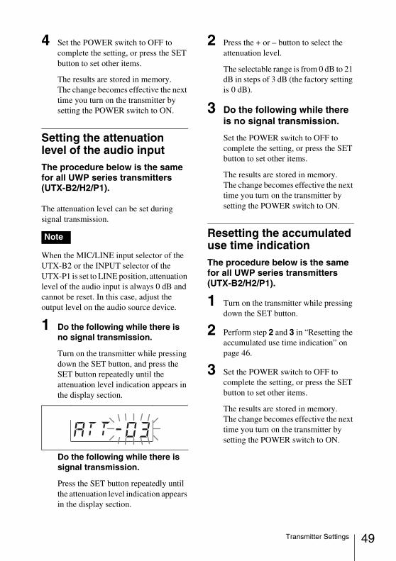
4 Set the POWER switch to OFF to complete the setting, or press the SET button to set other items.
The results are stored in memory.The change becomes effective the next time you turn on the transmitter by setting the POWER switch to ON.
Setting the attenuation level of the audio inputThe procedure below is the same for all UWP series transmitters (UTX-B2/H2/P1).
The attenuation level can be set during signal transmission.
When the MIC/LINE input selector of the UTX-B2 or the INPUT selector of the UTX-P1 is set to LINE position, attenuation level of the audio input is always 0 dB and cannot be reset. In this case, adjust the output level on the audio source device.
1 Do the following while there is no signal transmission.
Turn on the transmitter while pressing down the SET button, and press the SET button repeatedly until the attenuation level indication appears in the display section.
Do the following while there is signal transmission.
Press the SET button repeatedly until the attenuation level indication appears in the display section.
2 Press the + or – button to select the attenuation level.
The selectable range is from 0 dB to 21 dB in steps of 3 dB (the factory setting is 0 dB).
3 Do the following while there is no signal transmission.
Set the POWER switch to OFF to complete the setting, or press the SET button to set other items.
The results are stored in memory.The change becomes effective the next time you turn on the transmitter by setting the POWER switch to ON.
Resetting the accumulated use time indicationThe procedure below is the same for all UWP series transmitters (UTX-B2/H2/P1).
1 Turn on the transmitter while pressing down the SET button.
2 Perform step 2 and 3 in “Resetting the accumulated use time indication” on page 46.
3 Set the POWER switch to OFF to complete the setting, or press the SET button to set other items.
The results are stored in memory.The change becomes effective the next time you turn on the transmitter by setting the POWER switch to ON.
Note
49Transmitter Settings
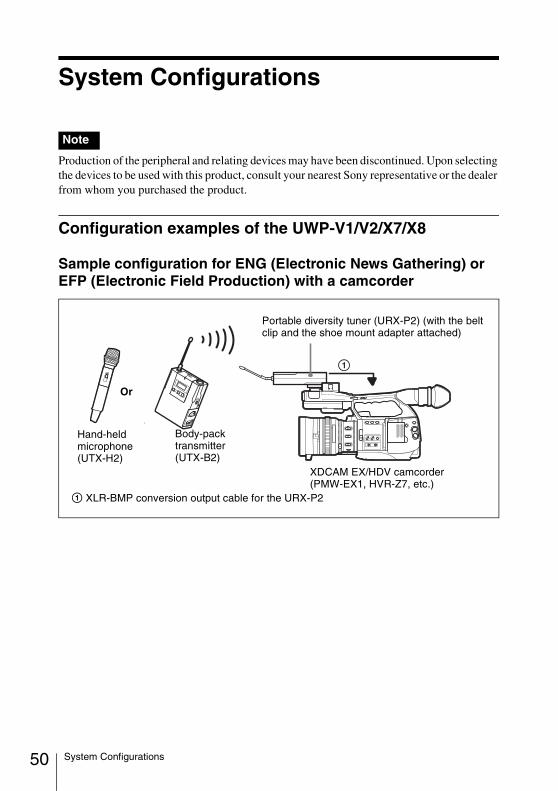
50
System Configurations
Production of the peripheral and relating devices may have been discontinued. Upon selecting the devices to be used with this product, consult your nearest Sony representative or the dealer from whom you purchased the product.
Configuration examples of the UWP-V1/V2/X7/X8
Sample configuration for ENG (Electronic News Gathering) or EFP (Electronic Field Production) with a camcorder
Note
Portable diversity tuner (URX-P2) (with the belt clip and the shoe mount adapter attached)
XDCAM EX/HDV camcorder (PMW-EX1, HVR-Z7, etc.)
Body-pack transmitter (UTX-B2)
1 XLR-BMP conversion output cable for the URX-P2
Hand-held microphone (UTX-H2)
Or
System Configurations
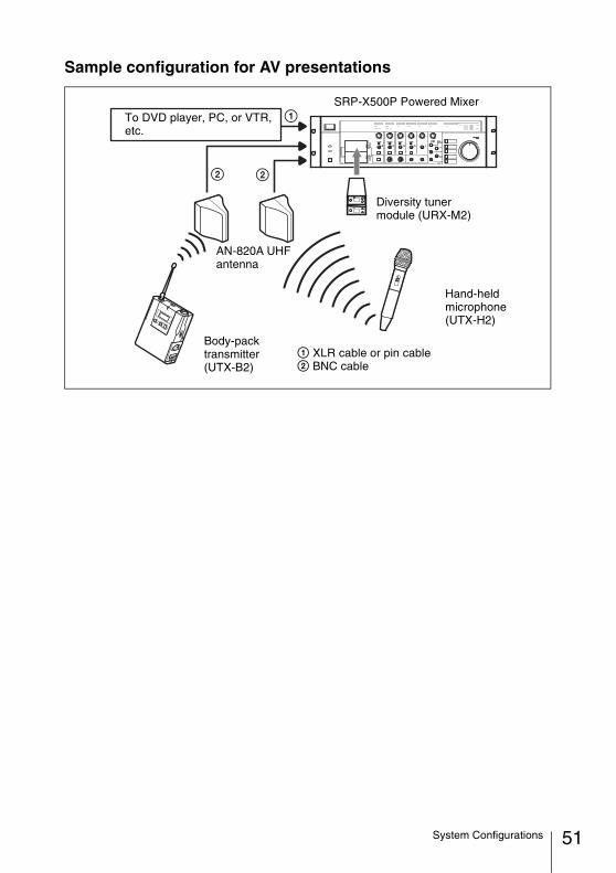
Sample configuration for AV presentations
SRP-X500P Powered MixerTo DVD player, PC, or VTR, etc.
Body-pack transmitter (UTX-B2)
AN-820A UHF antenna
Diversity tuner module (URX-M2)
1 XLR cable or pin cable2 BNC cable
Hand-held microphone (UTX-H2)
51System Configurations
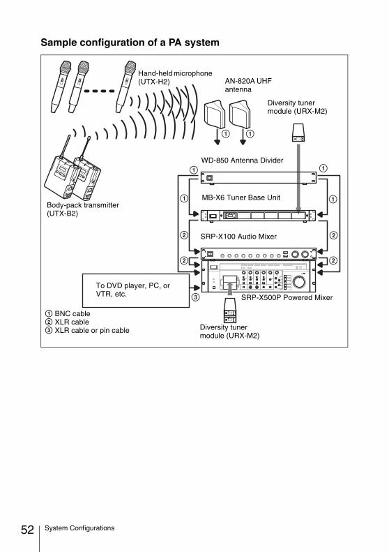
52
Sample configuration of a PA system
SRP-X500P Powered Mixer
To DVD player, PC, or VTR, etc.
Body-pack transmitter (UTX-B2)
AN-820A UHF antenna
MB-X6 Tuner Base Unit
WD-850 Antenna Divider
Diversity tuner module (URX-M2)
SRP-X100 Audio Mixer
1 BNC cable2 XLR cable3 XLR cable or pin cable
Hand-held microphone (UTX-H2)
Diversity tuner module (URX-M2)
System Configurations
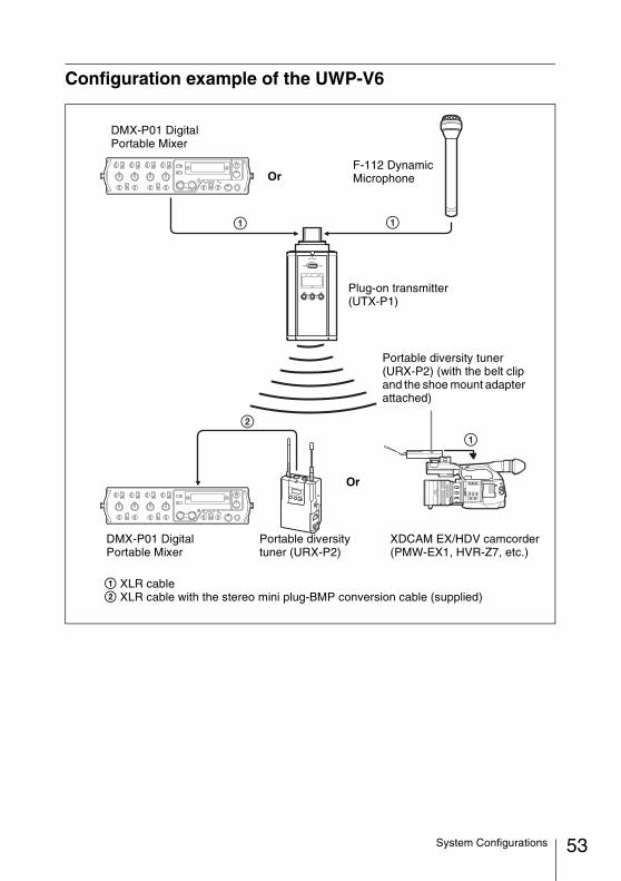
Configuration example of the UWP-V6
DMX-P01 Digital Portable Mixer
1 XLR cable2 XLR cable with the stereo mini plug-BMP conversion cable (supplied)
Portable diversity tuner (URX-P2)
XDCAM EX/HDV camcorder (PMW-EX1, HVR-Z7, etc.)
Portable diversity tuner (URX-P2) (with the belt clip and the shoe mount adapter attached)
DMX-P01 Digital Portable Mixer
Plug-on transmitter (UTX-P1)
Or
OrF-112 Dynamic Microphone
53System Configurations
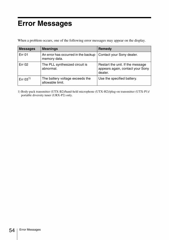
54
Error Messages
When a problem occurs, one of the following error messages may appear on the display.
1) Body-pack transmitter (UTX-B2)/hand-held microphone (UTX-H2)/plug-on transmitter (UTX-P1)/ portable diversity tuner (URX-P2) only.
Messages Meanings Remedy
Err 01 An error has occurred in the backup memory data.
Contact your Sony dealer.
Err 02 The PLL synthesized circuit is abnormal.
Restart the unit. If the message appears again, contact your Sony dealer.
Err 031) The battery voltage exceeds the allowable limit.
Use the specified battery.
Error Messages
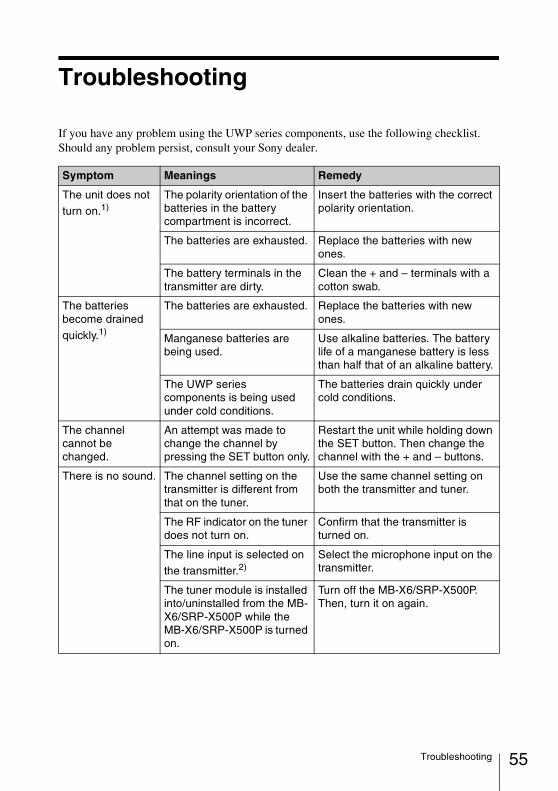
Troubleshooting
If you have any problem using the UWP series components, use the following checklist.Should any problem persist, consult your Sony dealer.
Symptom Meanings Remedy
The unit does not
turn on.1)The polarity orientation of the batteries in the battery compartment is incorrect.
Insert the batteries with the correct polarity orientation.
The batteries are exhausted. Replace the batteries with new ones.
The battery terminals in the transmitter are dirty.
Clean the + and – terminals with a cotton swab.
The batteries become drained
quickly.1)
The batteries are exhausted. Replace the batteries with new ones.
Manganese batteries are being used.
Use alkaline batteries. The battery life of a manganese battery is less than half that of an alkaline battery.
The UWP series components is being used under cold conditions.
The batteries drain quickly under cold conditions.
The channel cannot be changed.
An attempt was made to change the channel by pressing the SET button only.
Restart the unit while holding down the SET button. Then change the channel with the + and – buttons.
There is no sound. The channel setting on the transmitter is different from that on the tuner.
Use the same channel setting on both the transmitter and tuner.
The RF indicator on the tuner does not turn on.
Confirm that the transmitter is turned on.
The line input is selected on
the transmitter.2)Select the microphone input on the transmitter.
The tuner module is installed into/uninstalled from the MB-X6/SRP-X500P while the MB-X6/SRP-X500P is turned on.
Turn off the MB-X6/SRP-X500P. Then, turn it on again.
55Troubleshooting
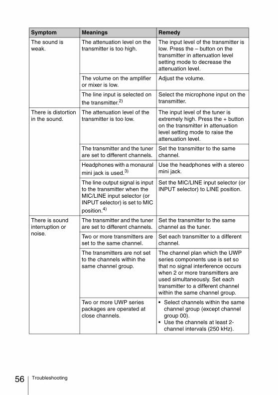
56
The sound is weak.
The attenuation level on the transmitter is too high.
The input level of the transmitter is low. Press the – button on the transmitter in attenuation level setting mode to decrease the attenuation level.
The volume on the amplifier or mixer is low.
Adjust the volume.
The line input is selected on
the transmitter.2)Select the microphone input on the transmitter.
There is distortion in the sound.
The attenuation level of the transmitter is too low.
The input level of the tuner is extremely high. Press the + button on the transmitter in attenuation level setting mode to raise the attenuation level.
The transmitter and the tuner are set to different channels.
Set the transmitter to the same channel.
Headphones with a monaural
mini jack is used.3)Use the headphones with a stereo mini jack.
The line output signal is input to the transmitter when the MIC/LINE input selector (or INPUT selector) is set to MIC
position.4)
Set the MIC/LINE input selector (or INPUT selector) to LINE position.
There is sound interruption or noise.
The transmitter and the tuner are set to different channels.
Set the transmitter to the same channel as the tuner.
Two or more transmitters are set to the same channel.
Set each transmitter to a different channel.
The transmitters are not set to the channels within thesame channel group.
The channel plan which the UWP series components use is set so that no signal interference occurs when 2 or more transmitters are used simultaneously. Set each transmitter to a different channel within the same channel group.
Two or more UWP series packages are operated at close channels.
• Select channels within the same channel group (except channel group 00).
• Use the channels at least 2-channel intervals (250 kHz).
Symptom Meanings Remedy
Troubleshooting
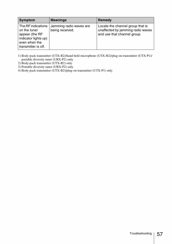
1) Body-pack transmitter (UTX-B2)/hand-held microphone (UTX-H2)/plug-on transmitter (UTX-P1)/ portable diversity tuner (URX-P2) only
2) Body-pack transmitter (UTX-B2) only3) Portable diversity tuner (URX-P2) only4) Body-pack transmitter (UTX-B2)/plug-on transmitter (UTX-P1) only
The RF indications on the tuner appear (the RF indicator lights up) even when the transmitter is off.
Jamming radio waves are being received.
Locate the channel group that is unaffected by jamming radio waves and use that channel group.
Symptom Meanings Remedy
57Troubleshooting
58
Important Notes on Use
On usage and storage• Operating the UWP series components
near electrical equipment (motors, transformers, or dimmers) may cause it to be affected by electromagnetic induction. Keep the UWP series components as far from such equipment as possible.
• The presence of the lighting equipment may produce electrical interference over the entire frequency range. Position the UWP series components so that interference is minimized.
• To avoid degradation of the signal to- noise ratio, do not use the UWP series components in noisy places or in locations subject to vibration, such as the following:- near electrical equipment, such as
motors, transformers or dimmers- near air conditioning equipment or
places subject to direct air flow from an air conditioner
- near public address loudspeakers- where adjacent equipment might
knock against the tunerKeep the UWP series components as far from such equipment as possible or use buffering material.
On cleaningClean the surface and the connectors of the UWP series components with a dry, soft cloth. Never use thinner, benzene, alcohol or any other chemicals, since these may mar the finish.
To prevent electromagnetic interference from portable communication devicesThe use of portable telephones and other communication devices near the UWP series components may result in malfunction and interference with audio signals. It is recommended that portable communication devices near the UWP series components be turned off.
Important Notes on Use
Specifications
Design and specifications are subject to change without notice.
Transmitters (UTX-B2/H2/P1)
Items common to all transmittersOscillator type
Crystal-controlled PLL synthesizerCarrier frequencies
Model available in USA: 566 to 590 MHz (U30 model), 638 to 662 MHz (U42 model)
Model available in Europe: 798 to 822 MHz (CE62 model), 838 to 862 MHz (CE67 model)
Operating frequency band24 MHz BW
Pre-emphasis50 µs
Distortion1.0% or less (–60 dBV, 1 kHz
input)Signal-to-noise ratio
60 dB or moreTone signal
32 kHzAttenuation
0 to 21 dB, in 3-dB stepsDisplay
Channel, frequency, audio level, RF level, accumulated use time
Power requirements3.0 V DC (two LR6/AA size
alkaline batteries)Operating temperature
0°C to 50°C (32°F to 122°F)Storage temperature
–20°C to +55°C (–4°F to +131°F)
Body-pack transmitter (UTX-B2)Antenna
1/4λ wave length wireAudio input connector
3.5-mm dia. mini jackReference audio input level
–60 dBV (at 0 dB attenuation level)RF output level
30 mW/5 mW selectableReference deviation
±7 kHz (–60 dBV, 1 kHz input)Frequency response
40 Hz to 18 kHzIndicator
AF/PEAK levelBattery life
Approx. 8 hours (measured with two Sony LR6/AA size alkaline batteries at 25°C (77°F), with output power of 30 mW)
NoteAlways verify that the unit is operating properly before use. SONY WILL NOT BE LIABLE FOR DAMAGES OF ANY KIND INCLUDING, BUT NOT LIMITED TO, COMPENSATION OR REIMBURSEMENT ON ACCOUNT OF THE LOSS OF PRESENT OR PROSPECTIVE PROFITS DUE TO FAILURE OF THIS UNIT, EITHER DURING THE WARRANTY PERIOD OR AFTER EXPIRATION OF THE WARRANTY, OR FOR ANY OTHER REASON WHATSOEVER.
59Specifications
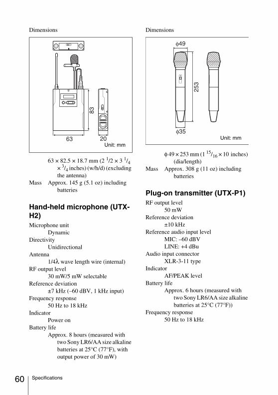
60
Dimensions
63 × 82.5 × 18.7 mm (2 1/2 × 3 1/4 × 3/4 inches) (w/h/d) (excluding the antenna)
Mass Approx. 145 g (5.1 oz) including batteries
Hand-held microphone (UTX-H2)Microphone unit
DynamicDirectivity
UnidirectionalAntenna
1/4λ wave length wire (internal)RF output level
30 mW/5 mW selectableReference deviation
±7 kHz (–60 dBV, 1 kHz input)Frequency response
50 Hz to 18 kHzIndicator
Power onBattery life
Approx. 8 hours (measured with two Sony LR6/AA size alkaline batteries at 25°C (77°F), with output power of 30 mW)
Dimensions
φ 49 × 253 mm (1 15/16 × 10 inches) (dia/length)
Mass Approx. 308 g (11 oz) including batteries
Plug-on transmitter (UTX-P1)RF output level
50 mWReference deviation
±10 kHzReference audio input level
MIC: –60 dBVLINE: +4 dBu
Audio input connectorXLR-3-11 type
IndicatorAF/PEAK level
Battery lifeApprox. 6 hours (measured with
two Sony LR6/AA size alkaline batteries at 25°C (77°F))
Frequency response50 Hz to 18 kHz
Unit: mmUnit: mm
Specifications
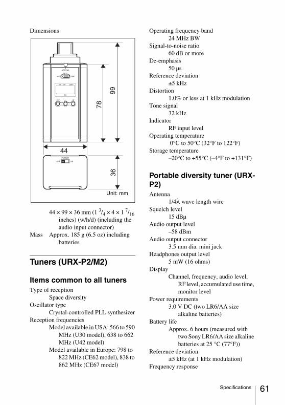
Dimensions
44 × 99 × 36 mm (1 3/4 × 4 × 1 7/16 inches) (w/h/d) (including the audio input connector)
Mass Approx. 185 g (6.5 oz) including batteries
Tuners (URX-P2/M2)
Items common to all tunersType of reception
Space diversityOscillator type
Crystal-controlled PLL synthesizerReception frequencies
Model available in USA: 566 to 590 MHz (U30 model), 638 to 662 MHz (U42 model)
Model available in Europe: 798 to 822 MHz (CE62 model), 838 to 862 MHz (CE67 model)
Operating frequency band24 MHz BW
Signal-to-noise ratio60 dB or more
De-emphasis50 µs
Reference deviation±5 kHz
Distortion1.0% or less at 1 kHz modulation
Tone signal32 kHz
IndicatorRF input level
Operating temperature 0°C to 50°C (32°F to 122°F)
Storage temperature–20°C to +55°C (–4°F to +131°F)
Portable diversity tuner (URX-P2)Antenna
1/4λ wave length wireSquelch level
15 dBµAudio output level
–58 dBmAudio output connector
3.5 mm dia. mini jackHeadphones output level
5 mW (16 ohms)Display
Channel, frequency, audio level, RF level, accumulated use time, monitor level
Power requirements3.0 V DC (two LR6/AA size
alkaline batteries)Battery life
Approx. 6 hours (measured with two Sony LR6/AA size alkaline batteries at 25 °C (77°F))
Reference deviation±5 kHz (at 1 kHz modulation)
Frequency response
Unit: mm
61Specifications
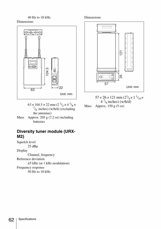
62
40 Hz to 18 kHzDimensions
63 × 104.5 × 22 mm (2 1/2 × 4 1/8 × 7/8 inches) (w/h/d) (excluding the antennas)
Mass Approx. 205 g (7.2 oz) including batteries
Diversity tuner module (URX-M2)Squelch level
25 dBµDisplay
Channel, frequencyReference deviation
±5 kHz (at 1 kHz modulation)Frequency response
50 Hz to 18 kHz
Dimensions
57 × 26 × 121 mm (21/4 × 1 1/16 × 4 7/8 inches) (w/h/d)
Mass Approx. 150 g (5 oz)
Unit: mm
Unit: mm
Specifications

Sony Corporation