Embed Size (px)
Citation preview

Compressed Video Over NetworksEditors: Ming-Tin Sun and Amy R. Reibman
Chapter 12: Wireless VideoBernd Girod and Niko F�arber
Telecommunications LaboratoryUniversity of Erlangen-Nuremberg
Cauerstrasse 7, 91058 Erlangen, GermanyPhone: +49 9131 8527100Fax: +49 9131 8528849
[email protected]@LNT.de
Nov. 14, 1999
1

1 Introduction
In the last decade, both mobile communications and multimedia communications haveexperienced unequaled rapid growth and commercial success. Naturally, the great {albeit separate { successes in both areas fuel the old vision of ubiquitous multimediacommunication { being able to communicate from anywhere at any time with anytype of data. The convergence of mobile and multimedia is now underway. Buildingon advances in network infrastructure, low-power integrated circuits, and powerfulsignal processing/compression algorithms, wireless multimedia services will likely �ndwidespread acceptance in the next decade. The goals of current second-generationcellular and cordless communications standards { supporting integrated voice and data{ are being expanded in third-generation wireless networks to provide truly ubiquitousaccess and integrated multimedia services. This vision is shared by many, e.g., byEricsson's GSM pioneer Jan Uddenfeldt when he writes \The tremendous growth ofInternet usage is the main driver for third-generation wireless. Text, audio, and image(also moving) will be the natural content, i.e., multimedia, for the user." [1].
Video communication is an indispensable modality of multimedia, most promi-nently exempli�ed by the Internet-based World Wide Web today. After the Webbrowser itself, audio/video streaming decoders have been the most frequently down-loaded Internet application, and they will be part of the browser software by the timethis chapter appears in print. Real-time audiovisual communication will also be anintegral part of third-generation wireless communication services. The current visionincludes a small handheld device that allows the user to communicate from anywherein the world with anyone in a variety of formats (voice, data, image, and full-motionvideo) from virtually any geographic location. This next generation of wireless multi-media communicators is expected to be equipped with a camera, a microphone, anda liquid crystal color display, serving both as a videophone and computer screen. Theconventional lap-top keyboard is likely to be replaced by a writing tablet, facilitatingoptical handwriting recognition and signature veri�cation. With progressing miniatur-ization of components, wristwatch \Dick Tracy" communicators are expected to followsoon after.
Of all modalities desirable for future mobile multimedia systems, motion video isthe most demanding in terms of bit-rate, and is hence likely to have the strongest im-pact on network architecture and protocols. Even with state-of-the-art compression,television quality requires a few Megabits per second (Mbps), while for low-resolution,limited-motion video sequences, as typically encoded for picturephones, a few tens ofkbps are required for satisfactory picture quality [2]. Today's \second-generation" cel-lular telephony networks, such as Global System for Mobile Communications (GSM),typically provide 10 - 15 kbps, suitable for compressed speech, but too little for mo-tion video. Fortunately, the standardization of higher-bandwidth networks, such asUniversal Mobile Telecommunications System (UMTS) [3] [4], is well underway, and,together with continued progress in video compression technology, wireless multimediacommunicators with picturephone functionality and Internet videoserver access will bepossible.
Beyond the limited available bit-rate, wireless multimedia transmission o�ers anumber of interesting technical challenges. A recent review has appeared in [5]. Oneof the more diÆcult issues is due to the fact that mobile networks cannot provide aguaranteed quality of service, because high bit error rates occur during fading periods.Transmission errors of a mobile wireless radio channel range from single bit errors toburst errors or even an intermittent loss of the connection. The classic technique tocombat transmission errors is Forward Error Correction (FEC), but its e�ectivenessis limited due to widely varying error conditions. A worst case design would lead toa prohibitive amount of redundancy. Closed-loop error control techniques like Auto-
2

matic Repeat reQuest (ARQ) [6] have been shown to be more e�ective than FEC andsuccessfully applied to wireless video transmission [7] [8]. Retransmission of corrupteddata frames, however, introduces additional delay, which might be unacceptable forreal-time conversational or interactive services. As a result, transmission errors can-not be avoided with a mobile radio channel, even when FEC and ARQ are combined.Therefore, the design of a wireless video system always involves a trade-o� betweenchannel coding redundancy that protects the bit-stream and source coding redundancydeliberately introduced for greater error resilience of the video decoder.
Without special measures, compressed video signals are extremely vulnerableagainst transmission errors. Basically, every bit counts. Considering speci�cally lowbit-rate video, compression schemes rely on interframe coding for high coding eÆ-ciency, i.e., they use the previous encoded and reconstructed video frame to predictthe next frame. Therefore, the loss of information in one frame has considerable im-pact on the quality of the following frames. Since some residual transmission errorswill inevitably corrupt the video bit-stream, this vulnerability precludes the use of lowbit-rate video coding schemes designed for error-free channels without special mea-sures. These measures have to be built into the video coding and decoding algorithmsthemselves and form the \last line of defense" if techniques like FEC and ARQ fail.
A comprehensive review of the great variety of error control and concealment tech-niques that have been proposed during the last 10 - 15 years has been presented inan excellent paper by Wang and Zhu recently [9] and is also included in Chapter 6 ofthis book. For example, one can partition the bit-stream into classes of di�erent errorsensitivity (often referred to as data partitioning) to enable the use of unequal errorprotection [10] [11] [12]. Data partitioning has been included as an error resiliencetool in the MPEG-4 standard [13]. Unequal error protection can signi�cantly increasethe robustness of the transmission and provide graceful degradation of the picturequality in case of a deteriorating channel. Since unequal error protection does notincorporate information about the current state of the mobile channel, the design ofsuch a scheme is a compromise that accommodates a range of operating conditions.Feedback-based techniques, on the other hand, can adjust to the varying transmissionconditions rapidly and make more e�ective use of the channel. This leads us to thenotion of channel-adaptive source coding.
The ITU-T Study Group 16 has adopted feedback-based error control in their ef-fort towards mobile extensions of the successful Recommendation H.263 (see Chapter1, \H-Series Video Coding Standards") for low bit-rate video coding. The �rst ver-sion of H.263 already included Error Tracking, a technique that allows the encoderto accurately estimate interframe error propagation and adapt its encoding strategyto mitigate the e�ects of past transmission errors [14] [15]. The second version, in-formally known as H.263+, was adopted by the ITU-T in February 1998. Amongmany other enhancements, it contains two new optional modes supporting ReferencePicture Selection (Annex N) and Independent Segment Decoding (Annex R) as anerror con�nement technique [16] [17]. Additional enhancements, for example, datapartitioning, unequal error protection, and reversible variable length coding, are un-der consideration for future versions of the standard, informally known as H.263++and H.26L.
Most of the error control schemes for wireless video are pragmatic engineeringsolutions to a problem at hand that do not generalize. The trade-o�s in designingthe overall transmission chain are not well-understood and need further study thatultimately should lead to a general theoretical framework for joint optimization ofsource coding, channel coding and transport protocols, coding schemes with superiorrobustness and adaptability to adverse transmission condition, and multimedia-awaretransport protocols that make most eÆcient use of limited wireless network resources.In the meantime, we have to be content with more modest goals.
3

In this chapter, we investigate the performance and trade-o�s when using estab-lished error control techniques for wireless video. We set the stage by discussing thebasic trade-o� between source and channel coding redundancy in Section 2 and intro-duce the distortion-distortion function as a formal tool for comparing wireless videosystems. In Section 3, we brie y discuss how to combat transmission errors by channelcoding and illustrate the problems that are encountered with classic FEC applied toa fading channel. We also discuss error ampli�cation that can occur with IP packeti-zation over wireless channels. In Section 3, we discuss error resilience techniques forlow bit-rate video, with particular emphasis on techniques adopted by the ITU-T aspart of the H.263 Recommendation. These techniques include feedback-based errorcontrol, yielding in e�ect a channel-adaptive H.263 encoder. The various approachesare compared by means of their operational distortion-distortion function under thesame experimental conditions.
2 Trading O� Source and Channel Coding
Naturally, the problem of transmitting video over noisy channels involves both sourceand channel coding. The classic goal of source coding is to achieve the lowest possibledistortion for a given target bit-rate. This goal has a fundamental limit in the rate-distortion bound for given source statistics. The source-coded bitstream then needsto be transmitted reliably over a noisy channel. Similar to the rate-distortion boundin source coding, the channel capacity quanti�es the maximum rate at which infor-mation can be transmitted reliably over the given channel. Hence, the classic goal ofchannel coding is to deliver reliable information at a rate that is as close as possibleto the channel capacity. According to Shannon's Separation Principle, it is possibleto independently consider source and channel coding without loss in performance [18].However, this important information-theoretic result is based on several assumptionsthat might break down in practice. In particular, it is based on (1) the assumption ofan in�nite block length for both source and channel coding (and hence in�nite delay)and (2) an exact and complete knowledge of the statistics of the transmission channel.As a corollary of (2), the Separation Principle applies only to point-to-point commu-nications and is not valid for multiuser or broadcast scenarios [18]. Therefore, JointSource-Channel Coding (JSC coding) can be advantageous in practice.
A joint optimization of source and channel coding can be achieved by exploitingthe redundancy in the source signal for channel decoding (source-controlled channeldecoding, e.g., [19]) or by designing the source codec for a given channel characteristic(channel-optimized source coding, e.g., [20]). In either case, source and channel codingcan hardly be separated anymore and are truly optimized jointly. Unfortunately,joint source-channel coding schemes for video are in their infancy today. A pragmaticapproach for today's state-of-the-art is to keep the source coder and the channel coderseparate, but optimize their parameters jointly. This approach will be followed in thischapter. A key problem of this optimization is the bit allocation between the sourceand channel coder that will be discussed below. To illustrate the problem we �rstconsider the typical components of a wireless video system. For more information onseparate, concatenated, and joint source-channel coding for wireless video see [21].
2.1 Components of a Wireless Video System
Fig. 1 shows the basic components of a wireless video system. The space-time dis-crete input video signal i[x; y; t] is fed into a video encoder. The video encoder ischaracterized by its operational distortion{rate function De(Re), where e[x; y; t] is thereconstructed video signal at the encoder and Re, De are the average rate and av-
4
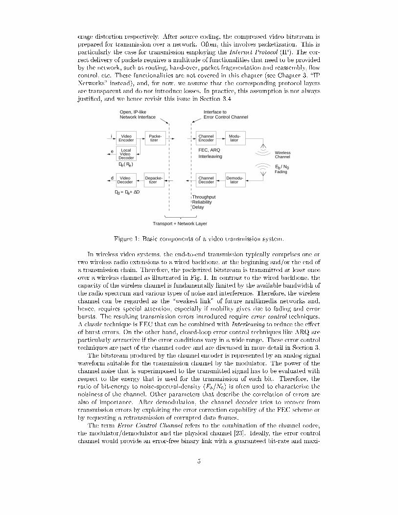
erage distortion respectively. After source coding, the compressed video bitstream isprepared for transmission over a network. Often, this involves packetization. This isparticularly the case for transmission employing the Internet Protocol (IP). The cor-rect delivery of packets requires a multitude of functionalities that need to be providedby the network, such as routing, hand-over, packet fragmentation and reassembly, owcontrol, etc. These functionalities are not covered in this chapter (see Chapter 3, \IPNetworks" instead), and, for now, we assume that the corresponding protocol layersare transparent and do not introduce losses. In practice, this assumption is not alwaysjusti�ed, and we hence revisit this issue in Section 3.4
DecoderVideo
tizerVideo
EncoderPacke-
Fading
Wireless
Interface to
DelayReliability
Channele
DecoderVideoLocal
Transport + Network Layer
Interleaving
Depacke-tizer
d
Open, IP-like
Throughput
FEC, ARQ
Network Interface Error Control Channel
ChannelDecoder
Modu-
latorDemodu-
lator
D = +d eD ∆
ChannelEncoder
D
bRe
0E / ND
i
( )e
Figure 1: Basic components of a video transmission system.
In wireless video systems, the end-to-end transmission typically comprises one ortwo wireless radio extensions to a wired backbone, at the beginning and/or the end ofa transmission chain. Therefore, the packetized bitstream is transmitted at least onceover a wireless channel as illustrated in Fig. 1. In contrast to the wired backbone, thecapacity of the wireless channel is fundamentally limited by the available bandwidth ofthe radio spectrum and various types of noise and interference. Therefore, the wirelesschannel can be regarded as the \weakest link" of future multimedia networks and,hence, requires special attention, especially if mobility gives rise to fading and errorbursts. The resulting transmission errors introduced require error control techniques.A classic technique is FEC that can be combined with Interleaving to reduce the e�ectof burst errors. On the other hand, closed-loop error control techniques like ARQ areparticularly attractive if the error conditions vary in a wide range. These error controltechniques are part of the channel codec and are discussed in more detail in Section 3.
The bitstream produced by the channel encoder is represented by an analog signalwaveform suitable for the transmission channel by the modulator. The power of thechannel noise that is superimposed to the transmitted signal has to be evaluated withrespect to the energy that is used for the transmission of each bit. Therefore, theratio of bit-energy to noise-spectral-density (Eb=N0) is often used to characterize thenoisiness of the channel. Other parameters that describe the correlation of errors arealso of importance. After demodulation, the channel decoder tries to recover fromtransmission errors by exploiting the error correction capability of the FEC scheme orby requesting a retransmission of corrupted data frames.
The term Error Control Channel refers to the combination of the channel codec,the modulator/demodulator and the physical channel [23]. Ideally, the error controlchannel would provide an error-free binary link with a guaranteed bit-rate and maxi-
5
mum delay to the video coder. However, as we will see in Section 3, the e�ectiveness ofchannel coding is limited in a mobile environment when data have to be transmittedwith low delay. Essentially, only a compromise between (1) reliability, (2) throughput,and (3) delay can be achieved. This fundamental trade-o� is typical for the commu-nication over noisy channels and has to be considered for the design of wireless videosystems.
Because the error control channel has to balance reliability, throughput, and delay,some residual transmission errors usually remain after channel decoding, especially forlow-latency applications. In this case, the video decoder must be capable of processingan erroneous bitstream. The residual errors cause an additional distortion �D suchthat the decoded video signal d[x; y; t] contains the total average distortion Dd =De +�D.
2.2 Distortion Measures
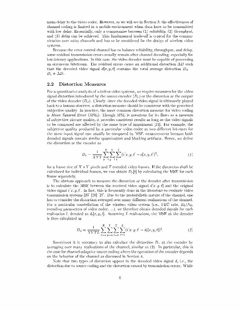
For a quantitative analysis of wireless video systems, we require measures for the videosignal distortion introduced by the source encoder (De) or the distortion at the outputof the video decoder (Dd). Clearly, since the decoded video signal is ultimately playedback to a human observer, a distortion measure should be consistent with the perceivedsubjective quality. In practice, the most common distortion measure for video codingis Mean Squared Error (MSE). Though MSE is notorious for its aws as a measureof subjective picture quality, it provides consistent results as long as the video signalsto be compared are a�ected by the same type of impairment [24]. For example, thesubjective quality produced by a particular video codec at two di�erent bit-rates forthe same input signal can usually be compared by MSE measurements because bothdecoded signals contain similar quantization and blocking artifacts. Hence, we de�nethe distortion at the encoder as
De =1
XY T
XX
x=1
YX
y=1
TX
t=1
(i[x; y; t]� e[x; y; t])2; (1)
for a frame size of X�Y pixels and T encoded video frames. If the distortion shall becalculated for individual frames, we can obtain De[t] by calculating the MSE for eachframe separately.
The obvious approach to measure the distortion at the decoder after transmissionis to calculate the MSE between the received video signal d[x; y; t] and the originalvideo signal i[x; y; t]. In fact, this is frequently done in the literature to evaluate videotransmission systems [25] [26] [27]. Due to the probabilistic nature of the channel, onehas to consider the distortion averaged over many di�erent realizations of the channel.For a particular constellation of the wireless video system (i.e., FEC rate, Eb=N0,encoding parameters of video codec, ...), we therefore obtain decoded signals for eachrealization l, denoted as dl[x; y; t]. Assuming L realizations, the MSE at the decoderis then calculated as
Dd =1
XY TL
XX
x=1
YX
y=1
TX
t=1
LX
l=1
(i[x; y; t]� dl[x; y; t])2: (2)
Sometimes it is necessary to also calculate the distortion De at the encoder byaveraging over many realizations of the channel, similar to (2). In particular, this isthe case for channel-adaptive source coding where the operation of the encoder dependson the behavior of the channel as discussed in Section 4.
Note that two types of distortion appear in the decoded video signal d, i.e., thedistortion due to source coding and the distortion caused by transmission errors. While
6
the former is adequately described by De, we de�ne
�D = Dd �De; (3)
to describe the latter. Typically, De is the result of small quantization errors that areevenly distributed over all encoded frames, while �D is dominated by strong errorsthat are concentrated in a small part of the picture and are (hopefully!) present onlyfor a short time. Because such errors are perceived very di�erently, an average measuresuch as Dd alone can be misleading if not applied carefully. Instead, both De and �Dshould be considered for the evaluation of video quality simultaneously as discussed inthe next section.
Before concluding this section, we note that MSE is commonly converted to peak-signal-to-noise ratio (PSNR) in the video coding community. PSNR is de�ned as10 log
10(2552=MSE), where 255 corresponds to the peak-to-peak range of the encoded
and decoded video signal (each quantized to 256 levels). It is expressed in decibels (dB)and increases with increasing picture quality. Though the logarithmic scale providesa better correlation with subjective quality, the same limitations as for MSE apply.As a rule of thumb for low bit-rate video coding (with clearly visible distortions), adi�erence of 1 dB generally corresponds to a noticeable di�erence while acceptablepicture quality requires values greater than 30 dB. Since PSNR is more commonlyused than MSE, we will use instead of (1), (2), and (3)
PSNRe = 10 log10
2552
De
; (4)
PSNRd = 10 log10
2552
Dd
; and (5)
�PSNR = PSNRe � PSNRd = 10 log10
De
Dd
= 10 log10
De
De +�D; (6)
when presenting experimental results. Now, after having de�ned the necessary distor-tion measures, we return to the problem of bit allocation between source and channelcoding by introducing the distortion-distortion function.
2.3 Distortion { Distortion Function
Consider again the wireless video transmission system illustrated in Fig. 1. Assumethat a modulation scheme is used which provides a constant \raw" bit-rate Rc. By op-erating the video encoder at a bit-rate Re � Rc, the remaining bit-rate Rc�Re can beutilized for error control information to increase the reliability of the transmission overthe wireless channel and thus reduce the Residual Word Error Rate (RWER) whichdescribes the probability of residual errors after channel decoding. As noted above,there is a fundamental trade-o� between throughput and reliability, corresponding tothe bit allocation between source and channel coding characterized by the code rater = Re=Rc.
Altering the bit allocation between source and channel coding has two e�ects onthe picture quality of the video signal d at the decoder output. First, a reduction ofr reduces the bit-rate available to the video encoder and thus degrades the picturequality at the encoder regardless of transmission errors. The actual PSNRe reductionis determined by the operational distortion-rate function De(Re) of the video encoder.On the other hand, the residual error rate is reduced when reducing r, determinedby the properties of the error control channel, i.e., the channel codec, the modulationscheme, and the characteristic of the channel. Finally, a reduction in RWER leads to areduction in �PSNR depending on several implementation issues, such as resynchro-nization, packetization, and error concealment, all of which are associated with the
7
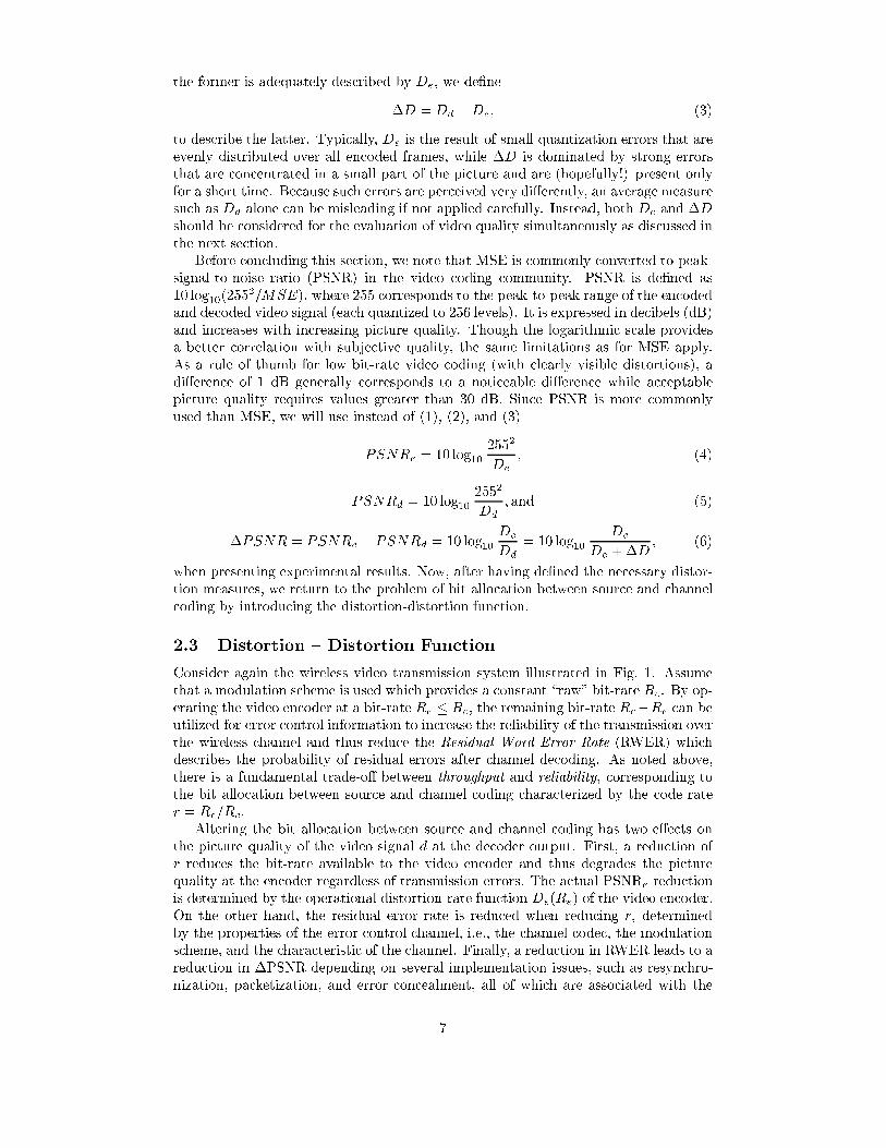
video decoder. The interaction of the various characteristics are illustrated in Fig. 2.The upper right graph shows the resulting trade-o� between PSNRe and �PSNR andprovides a compact overview of the overall system behavior. Because the curve showsthe dependency between two distortion measures, we refer to it as the operationalDistortion { Distortion Function (DDF). Note that the overall picture quality at thedecoder, PSNRd, increases from top-left towards bottom-right as illustrated in the�gure. Therefore, if desired, DDFs can also be used to evaluate the overall distortion.
Err
or C
ontr
ol C
hann
elV
ideo
Dec
oder
Function (DDF)Distortion-Distortion
Video E
ncoderr = 1
r = 0
r
RWER
d
PSNR∆
PSNRe
PSNR
Figure 2: Interaction of system components when varying the bit allocation betweensource and channel coding, characterized by the channel code rate r. PSNRe is thepicture quality after encoding and �PSNR is the loss of picture quality caused byresidual errors. An important system parameter of the error control channel is theresidual word error rate (RWER). The upper right curve is the Distortion { DistortionFunction of the wireless video system and is a compact description of the overallperformance.
The DDF is a useful tool to study the in uence of parameters or algorithms inthe video codec for a given error control channel. Instead of building a combineddistortion measure, both distortion types are available to evaluate the resulting systemperformance without additional assumption of how they have to be combined, as longas subjective quality decreases with both increasing De and increasing �D.
As pointed out in Section 2.2, De is a useful distortion measure for source coding aslong as the video signal is impaired by the same kind of distortion. More formally, letQ be the average subjective video quality as perceived by a representative group of testpersons. For De to be useful for coder optimization, we require that Q � f(De) for theset of impaired video sequences considered, where f(:) is a monotonically decreasingfunction. The exact form of f(:) is irrelevant. With a similar argument, �D is usefulto optimize the error control channel and the video decoder, if the subjective qualityQ � g(�D), where g(:) is monotonically decreasing.
For the joint optimization of source and channel coding, we require a subjectivequality function Q � h(De;�D) that captures the superposition of the two di�erenttypes of distortions. Unfortunately, measuring h(:; :) would require tedious subjectivetests, and no such tests have been carried out to the authors' best knowledge. Never-
8
theless, we can safely assume that h(:; :) would be monotonically decreasing with De
and �D, and, fortunately, this monotonicity condition is often all we need when usingDDFs to evaluate and compare error resilience techniques. In many situations, DDFsto be compared do not intersect in a wide range of Dd and �D. In this case it ispossible to pick the best scheme for any Q � h(De;�D) as long as the monotonicitycondition holds. This greatly simpli�es the evaluation of video transmission systems,since the diÆcult question of a combined subjective quality measure for source codingand transmission error distortion is circumvented.
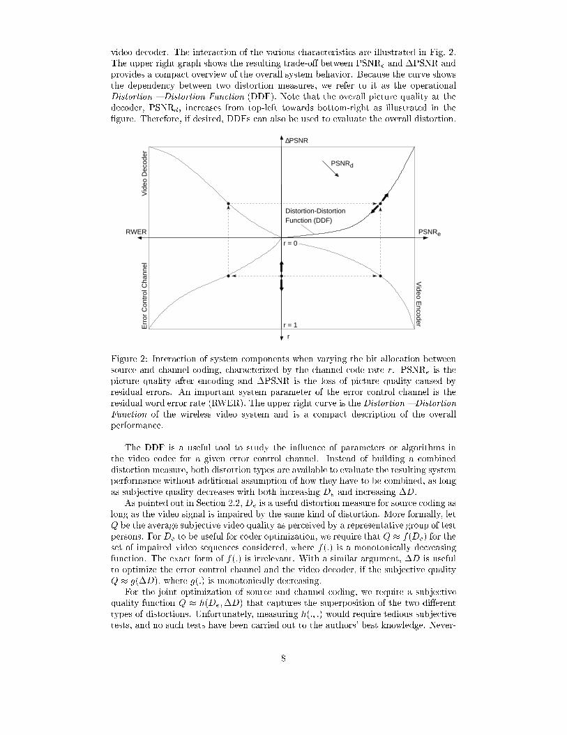
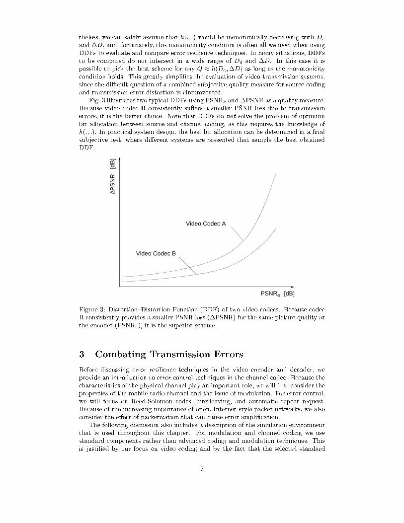
Fig. 3 illustrates two typical DDFs using PSNRe and �PSNR as a quality measure.Because video codec B consistently su�ers a smaller PSNR loss due to transmissionerrors, it is the better choice. Note that DDFs do not solve the problem of optimumbit allocation between source and channel coding, as this requires the knowledge ofh(:; :). In practical system design, the best bit allocation can be determined in a �nalsubjective test, where di�erent systems are presented that sample the best obtainedDDF.
[dB]
[dB
]
Video Codec B
Video Codec A
PSNRe
PS
NR
∆
Figure 3: Distortion{Distortion Function (DDF) of two video codecs. Because codecB consistently provides a smaller PSNR loss (�PSNR) for the same picture quality atthe encoder (PSNRe), it is the superior scheme.
3 Combating Transmission Errors
Before discussing error resilience techniques in the video encoder and decoder, weprovide an introduction to error control techniques in the channel codec. Because thecharacteristics of the physical channel play an important role, we will �rst consider theproperties of the mobile radio channel and the issue of modulation. For error control,we will focus on Reed-Solomon codes, interleaving, and automatic repeat request.Because of the increasing importance of open, Internet-style packet networks, we alsoconsider the e�ect of packetization that can cause error ampli�cation.
The following discussion also includes a description of the simulation environmentthat is used throughout this chapter. For modulation and channel coding we usestandard components rather than advanced coding and modulation techniques. Thisis justi�ed by our focus on video coding and by the fact that the selected standard
9
components are well suited to illustrate the basic problems and trade-o�s. Most of theconclusions that are derived in later sections also apply to other scenarios because theunderlying concepts are very general. For more information on coding and modulationtechniques that are employed in the next generation mobile networks, we refer toChapter 5 \Wireless Networks". These are not discussed in detail below because theinterface to the error control channel will behave similarly, resulting in similar problemsand solutions on the source coding level.
3.1 Characteristics of the Mobile Radio Channel
The mobile radio channel is a hostile medium. Besides absorption, the propagation ofelectromagnetic waves is in uenced by three basic mechanisms: re ection, di�raction,and scattering. In conjunction with mobility of the transmitter and/or receiver, thesemechanisms cause several phenomena, such as time-varying delay spread or spectralbroadening, which can severely impair the transmission. These will be brie y discussedin the following. More information can be found in Chapter 5 \Wireless Networks"or [28] [29] [30]. The intention of this section is to show that the underlying physicalmechanisms result in fundamental performance limits for wireless transmission. As aresult, the use of error control techniques in the video codec is of increased importance.
When a mobile terminal moves within a larger area, the distance between theradio transmitter and receiver often varies signi�cantly. Furthermore, the number andtype of objects between transmitter and receiver usually changes and might causeshadowing. The resulting attenuation of radio frequency (RF) power is described bythe path loss. In an outdoor environment, the path loss is a�ected by hills, forests,or buildings. In an indoor environment, the electromagnetic properties of blockingwalls and ceilings are of importance. The e�ect of these objects and the distance tothe transmitter can be described by empirical models [28] [30]. Usually, these modelsinclude a mean path loss as a function of distance (nth power law) and a randomvariation about that mean (log-normal distribution). For our experimental results inthis chapter we assume that the path loss is constant for the duration of a simulation(approximately 10 seconds), and hence assume constant (average) Eb=N0.
Besides large-scale fading as described by path loss, small changes in position canalso result in dramatic variations of RF energy. This small-scale fading is a charac-teristic e�ect in mobile radio communication and is caused by multipath propagation.In a wireless communication system, a signal can travel from transmitter to receiverover multiple re ective paths. Each re ection arrives from a di�erent direction with adi�erent delay and, hence, for a narrowband signal, undergoes a di�erent attenuationand phase shift. The superposition of these individual signal components can causeconstructive and destructive interference alternating at a small scale (as small as halfa wavelength). For a moving receiver, this space-variant signal strength is perceived asa time-variant channel, where the velocity of the mobile terminal determines the speedof uctuation. Small-scale fading is often associated with Rayleigh fading because, ifthe multiple re ective paths are large in number and equally signi�cant, the envelopeof the received signal is described by a Rayleigh pdf (probability density function).
An important problem caused by multipath propagation is delay spread. For asingle transmitted impulse, the time Tm between the �rst and last received componentsof signi�cant amplitude represents the maximum excess delay, which is an importantparameter to characterize the channel. If Tm is bigger than the symbol duration Ts,neighboring symbols interfere with each other, causing Intersymbol Interference (ISI).This channel type requires special mitigation techniques such as equalization and willnot be considered in the following. Instead, we focus on at fading channels, withTm < Ts. In this case, all the received multipath components of a symbol arrivewithin the symbol duration and no ISI is present. Here, the main degradation is
10

the destructive superposition of phasor components, which can yield a substantialreduction in signal amplitude. Note, however, that the error resilience techniquesdescribed in Section 4 are also applicable to ISI channels given appropriate channelcoding.
Similar to the delay spread in the time-domain, the received signal can also bespread in the frequency-domain. For a single transmitted sinusoid, the receiver mayobserve multiple signals at shifted frequency positions. This spectral broadening iscaused by the Doppler shift of an electromagnetic wave when observed from a movingobject. The amount of shift for each re ective path depends on the incident directionrelative to the velocity vector of the receiver. The maximum shift magnitude is calledthe Doppler frequency fD, which is equal to the mobile velocity divided by the carrierwavelength. For the dense-scatterer model, which assumes a uniform distribution ofre ections from all directions, the resulting Doppler power spectrum has a typical bowl-shaped characteristic with maximum frequency fD (also known as Jakes spectrum[29]). This model is frequently used in the literature to simulate the mobile radiochannel and is also used in this chapter. Note that the Doppler power spectrum has animportant in uence on the time-variant behavior of the channel because it is directlyrelated to the temporal correlation of the received signal amplitude via the Fouriertransform. For a given carrier frequency, the correlation increases with decreasingmobile velocity, such that slowly moving terminals encounter longer fades (and errorbursts). Therefore, fD is often used to characterize how rapidly the fading amplitudechanges.
In summary, mobile radio transmission has to cope with time-varying channel con-ditions of both large and small scale. These variations are mainly caused by the motionof the transmitter or the receiver resulting in propagation path changes. As a result,errors are not limited to single bit errors but tend to occur in bursts. In severe fad-ing situations the loss of synchronization may even cause an intermittent loss of theconnection. As we will see, this property makes it diÆcult to design error controltechniques that provide high reliability at high throughput and low delay.
3.2 Modulation
Since we cannot feed bits to the antenna directly, an appropriate digital modulationscheme is needed. Usually, a sinusoidal carrier wave of frequency fc is modi�ed inamplitude, phase, and/or frequency depending on the digital data that shall be trans-mitted. This results in three basic modulation techniques, known as Amplitude ShiftKeying (ASK), Frequency Shift Keying (FSK), and Phase Shift Keying (PSK). How-ever, other schemes and hybrids are also popular. In general, the modem operates ata �xed symbol rate Rs, such that its output signal is cyclostationary with the symbolinterval Ts = 1=Rs. In the most basic case, one symbol corresponds to one bit. Forexample, Binary PSK (BPSK) uses two waveforms with identical amplitude and fre-quency but a phase shift of 180 degrees. Higher order modulation schemes can choosefrom a larger set of waveforms, and hence provide higher bit-rates for the same symbolinterval, but they are also less robust against noise for the same average transmissionpower.
The choice of a modulation scheme is a key issue in the design of a mobile communi-cation system because each scheme possesses di�erent performance characteristics. Inmost cases, however, the selection of a modulation scheme reduces to a considerationof the power and bandwidth availability in the intended application. For example, incellular telephony the principle design goal is the minimization of spectral occupancyby a single user, such that the number of paying customers is maximized for the al-located radio spectrum. Thus, an issue of increasing importance for cellular systemsis to select bandwidth-eÆcient modulation schemes. On the other hand, the lifetime
11
of a portable battery also limits the energy that can be used for the transmission ofeach bit, Eb, and hence power eÆciency is also of importance. A detailed discussion ofmodulation techniques is beyond the scope of this chapter and the reader is referredto [31] [32] for detailed information.
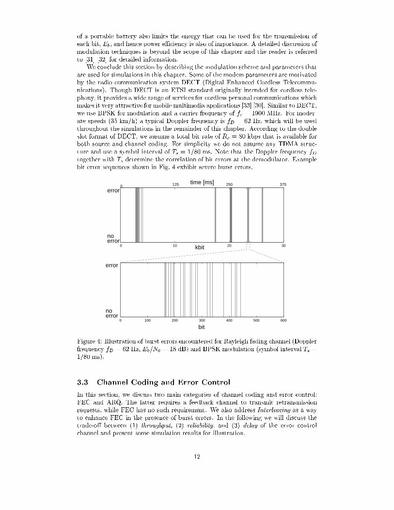
We conclude this section by describing the modulation scheme and parameters thatare used for simulations in this chapter. Some of the modem parameters are motivatedby the radio communication system DECT (Digital Enhanced Cordless Telecommu-nications). Though DECT is an ETSI standard originally intended for cordless tele-phony, it provides a wide range of services for cordless personal communications whichmakes it very attractive for mobile multimedia applications [33] [30]. Similar to DECT,we use BPSK for modulation and a carrier frequency of fc = 1900 MHz. For moder-ate speeds (35 km/h) a typical Doppler frequency is fD = 62 Hz, which will be usedthroughout the simulations in the remainder of this chapter. According to the doubleslot format of DECT, we assume a total bit rate of Rc = 80 kbps that is available forboth source and channel coding. For simplicity we do not assume any TDMA struc-ture and use a symbol interval of Ts = 1/80 ms. Note that the Doppler frequency fDtogether with Ts determine the correlation of bit errors at the demodulator. Examplebit error sequences shown in Fig. 4 exhibit severe burst errors.
0 10 20 30
0 100 200 300 400 500 600
250125
no
375time [ms]
kbit
bit
error
0
error
errorno
error
Figure 4: Illustration of burst errors encountered for Rayleigh fading channel (Dopplerfrequency fD = 62 Hz, Eb=N0 = 18 dB) and BPSK modulation (symbol interval Ts =1/80 ms).
3.3 Channel Coding and Error Control
In this section, we discuss two main categories of channel coding and error control:FEC and ARQ. The latter requires a feedback channel to transmit retransmissionrequests, while FEC has no such requirement. We also address Interleaving as a wayto enhance FEC in the presence of burst errors. In the following we will discuss thetrade-o� between (1) throughput, (2) reliability, and (3) delay of the error controlchannel and present some simulation results for illustration.
12
Forward Error Correction
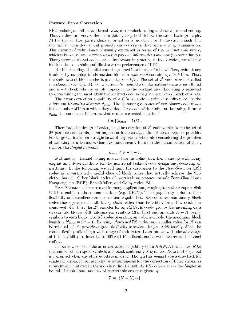
FEC techniques fall in two broad categories { block coding and convolutional coding.Though they are very di�erent in detail, they both follow the same basic principle.At the transmitter, parity check information is inserted into the bitstream such thatthe receiver can detect and possibly correct errors that occur during transmission.The amount of redundancy is usually expressed in terms of the channel code rate r,which takes on values between zero (no payload information) and one (no redundancy).Though convolutional codes are as important in practice as block codes, we will useblock codes to explain and illustrate the performance of FEC.
For block coding, the bitstream is grouped into blocks of k bits. Then, redundancyis added by mapping k information bits to a code word containing n > k bits. Thus,the code rate of block codes is given by r = k=n. The set of 2k code words is calledthe channel code C(n; k). For a systematic code, the k information bits are not alteredand n � k check bits are simply appended to the payload bits. Decoding is achievedby determining the most likely transmitted code word given a received block of n bits.
The error correction capability of a C(n; k) code is primarily in uenced by theminimum Hamming distance dmin. The Hamming distance of two binary code wordsis the number of bits in which they di�er. For a code with minimum Hamming distancedmin the number of bit errors that can be corrected is at least
t = b(dmin � 1)=2c:
Therefore, the design of codes, i.e., the selection of 2k code words from the set of2n possible codewords, is an important issue as dmin should be as large as possible.For large n, this is not straightforward, especially when also considering the problemof decoding. Furthermore, there are fundamental limits in the maximization of dmin,such as the Singleton bound
dmin � n� k + 1:
Fortunately, channel coding is a mature discipline that has come up with manyelegant and clever methods for the nontrivial tasks of code design and decoding al-gorithms. In the following, we will limit the discussion to the Reed-Solomon (RS)codes as a particularly useful class of block codes that actually achieve the Sin-gleton bound. Other block codes of practical importance include Bose-Chaudhuri-Hocquenghem (BCH), Reed-Muller, and Golay codes [23].
Reed-Solomon codes are used in many applications, ranging from the compact disk(CD) to mobile radio communications (e.g. DECT). Their popularity is due to their exibility and excellent error correction capabilities. RS codes are non-binary blockcodes that operate on multi-bit symbols rather than individual bits. If a symbol iscomposed of m bits, the RS encoder for an RS(N;K) code groups the incoming datastream into blocks of K information symbols (Km bits) and appends N �K paritysymbols to each block. For RS codes operating on m-bit symbols, the maximum blocklength is Nmax = 2m � 1. By using shortened RS codes, any smaller value for N canbe selected, which provides a great exibility in system design. Additionally, K can bechosen exibly, allowing a wide range of code rates. Later on, we will take advantageof this exibility to investigate di�erent bit allocations between source and channelcoding.
Let us now consider the error correction capability of an RS(N;K) code. Let E bethe number of corrupted symbols in a block containingN symbols. Note that a symbolis corrupted when any of its m bits is in error. Though this seems to be a drawback forsingle bit errors, it can actually be advantageous for the correction of burst errors, astypically encountered in the mobile radio channel. As RS codes achieve the Singletonbound, the minimum number of correctable errors is given by
T = b(N �K)=2c;
13
and the RS decoder can correct any pattern of symbol errors as long as E � T . Inother words, for every two additional parity symbols, an additional symbol error canbe corrected. If more than E symbol errors are contained in a block, the RS decodercan usually detect the error. For large blocks, undetected errors are very improbable,especially when the decoder backs o� from the Singleton bound for error correction(bounded distance decoding). The probability that a block cannot be corrected isusually described by the Residual Word Error Rate (RWER). In general, the RWERdecreases with increasing K and with increasing Eb=N0.
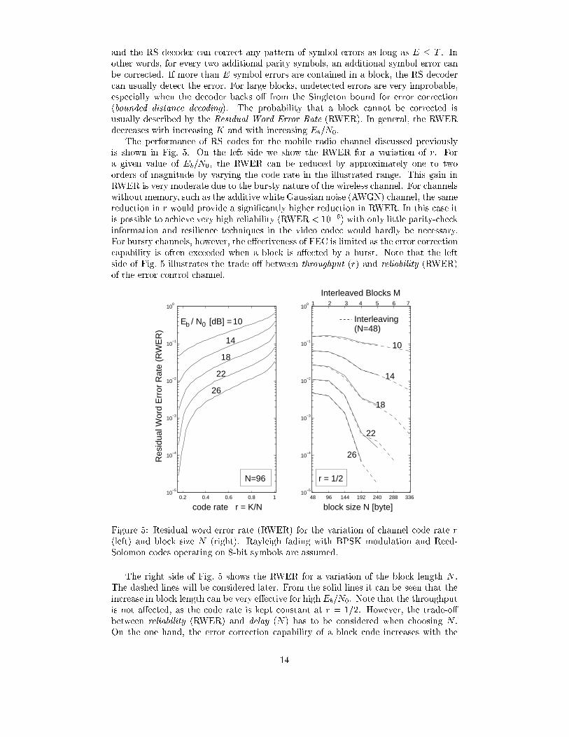
The performance of RS codes for the mobile radio channel discussed previouslyis shown in Fig. 5. On the left side we show the RWER for a variation of r. Fora given value of Eb=N0, the RWER can be reduced by approximately one to twoorders of magnitude by varying the code rate in the illustrated range. This gain inRWER is very moderate due to the bursty nature of the wireless channel. For channelswithout memory, such as the additive white Gaussian noise (AWGN) channel, the samereduction in r would provide a signi�cantly higher reduction in RWER. In this case itis possible to achieve very high reliability (RWER < 10�6) with only little parity-checkinformation and resilience techniques in the video codec would hardly be necessary.For bursty channels, however, the e�ectiveness of FEC is limited as the error correctioncapability is often exceeded when a block is a�ected by a burst. Note that the leftside of Fig. 5 illustrates the trade-o� between throughput (r) and reliability (RWER)of the error control channel.
0.2 0.4 0.6 0.8 110
−5
10−4
10−3
10−2
10−1
100
48 96 144 192 240 288 33610
−5
10−4
10−3
10−2
10−1
100
10
26
22
14
18
(N=48)
14
Res
idua
l Wor
d E
rror
Rat
e (R
WE
R)
22
code rate r = K/N block size N [byte]
18
26
r = 1/2
Interleaved Blocks M
Interleaving
4321
E / N [dB] =b 0
5
N=96
10
76
Figure 5: Residual word error rate (RWER) for the variation of channel code rate r(left) and block size N (right). Rayleigh fading with BPSK modulation and Reed-Solomon codes operating on 8-bit symbols are assumed.
The right side of Fig. 5 shows the RWER for a variation of the block length N .The dashed lines will be considered later. From the solid lines it can be seen that theincrease in block length can be very e�ective for high Eb=N0. Note that the throughputis not a�ected, as the code rate is kept constant at r = 1=2. However, the trade-o�between reliability (RWER) and delay (N) has to be considered when choosing N .On the one hand, the error correction capability of a block code increases with the
14
block length. On the other hand, long blocks introduce additional delay (assumingconstant code rate and source rate). Usually the acceptable delay is determined by theapplication. For �le transfer high delays in the order of several seconds are acceptable.For conversational services, such as voice or video telephony, a maximum round tripdelay of 250 ms should not be exceeded. For low-delay video applications, the frameinterval usually sets the upper bound. For example, assuming 12.5 fps video and atotal bit-rate of Rc = 80 kbps, the resulting maximum block length is n = 6400 bit.However, shorter blocks are preferable because other e�ects also contribute to theoverall delay.
Besides the limitations on N which are imposed by delay considerations, thereare also implementation and complexity constraints. In particular the decoding ofblock codes in case of errors is a task that becomes computationally demanding forlarge N . The number of bits that are combined to symbols in RS codes is usuallyless than and most commonly equal to 8, thus allowing a maximum block length ofNmax = 2m � 1 = 255 bytes.
Note that a limited block length can cause severe problems for FEC schemes whenthe transmission channel tends to burst errors. Either a block is a�ected by a burst, inwhich case the error correction capability is often exceeded, or the block is transmittederror-free and the additional redundancy is wasted. To overcome this limitation, FECis often enhanced by a technique known as Interleaving.
Interleaving
The idea behind interleaving is to spread the error burst in time. In a simple blockinterleaver, encoded blocks of N symbols are loaded into a rectangular matrix row byrow. After M rows are collected, the symbols are then read out column by column fortransmission. At the receiver, this reordering of symbols is inverted and the blocks arepassed to the FEC decoder. For burst errors, this e�ectively reduces the concentrationof errors in single code words, i.e., a burst of b consecutive symbol errors causes amaximum of b=M symbol errors in each code word. For large M , the interleaver/-deinterleaver pair thus creates in e�ect a memoryless channel. Though interleavingcan be implemented with low complexity it also su�ers from increased delay, dependingon the number of interleaved blocks M . The dashed lines on the right side of Fig. 5illustrate the e�ectiveness of interleaving in the given error control channel. As thebasic block length we use N = 48 symbols. For the same delay, essentially the sameperformance can be achieved as for increased block length, providing the same trade-o� between reliability and delay. However, also larger blocks than Nmax = 255 can beobtained at reduced complexity. Therefore interleaving is a frequently used techniquefor bursty channels if the additional delay is acceptable.
Automatic Repeat Request
Another error control technique that can be used to exchange reliability for delay andthroughput is Automatic Repeat reQuest (ARQ). In contrast to FEC, ARQ requires afeedback channel from the receiver to the transmitter, and therefore cannot be usedin systems where such a channel is not available (e.g., broadcasting).
For ARQ, the incoming bitstream is grouped into blocks, similar to FEC. Eachblock is extended by a header including a Sequence Number (SN) and an error de-tection code at the end of each block { often a Cyclic Redundancy Check (CRC).This information is used at the receiver for error detection and to request the retrans-mission of corrupted blocks using Positive Acknowledgments (ACKs) and/or NegativeAcknowledgments (NAKs) which are sent back via the feedback channel. Usually, re-transmissions are repeated until error-free data are received or a time-out is exceeded.
15

This basic operation can be implemented in various forms with di�erent implica-tions on throughput, complexity and delay. There are three basic ARQ schemes inuse: Stop And Wait (SW), Go Back N (GN), and Selective Repeat (SR) [6]. ThoughSR-ARQ requires bu�ering and reordering of out-of-sequence blocks, it provides thehighest throughput. Another possibility to enhance ARQ schemes is the combinationwith FEC, which is known as Hybrid ARQ. For a detailed analysis of throughput thereader is referred to [23] and [34], both of which also consider the case of noisy feedbackchannels. Furthermore, the application of ARQ in fading channels is analyzed in [35],while [36] proposes an ARQ protocol that adapts to a variable error rate by switchingbetween two modes.
One critical issue in ARQ is delay, because the duration between retransmissionattempts is determined by the Round Trip Delay (RTD). Thus, if the number ofnecessary retransmission attempts is A, the total delay until reception is at leastD = A � RTD. As A depends on the quality of the channel, the resulting delay andthroughput are not predictable and vary over time. For applications, where delay is notcritical, ARQ is an elegant and eÆcient error control technique, and it has been usedextensively, e.g., in the Transport Control Protocol (TCP) of the Internet. For real-time video transmission, however, the delay associated with classic ARQ techniques isoften unacceptable.
The situation has improved slightly in the past few years through delay-constrainedor soft ARQ protocols. One simple approach to limit delay with ARQ is to allow atmost A = D=RTD retransmissions, where D is the maximum acceptable delay. As thismay result in residual errors, the trade-o� reliability vs. delay has to be considered. Agiven maximum-delay constraint can also be met by adjusting the source rate of thevideo codec. If a close interaction between source coding and channel is possible, therate of the video codec can be directly controlled by the currently available throughput[37] [38]. The e�ectiveness of this approach for wireless video transmission over DECThas been demonstrated already in 1992 [7]. If such a close interaction is not possible,scalable video coding has to be used [8] [39] [40]. Other re�nements of ARQ schemesproposed for video include the retransmission of more strongly compressed video [41]or the retransmission of multiple copies [9] in a packet network. Nevertheless, ARQcan only be used for applications with relatively large acceptable delay and/or verylow RTDs { or with limited reliability.
3.4 IP over Wireless
Future wireless video applications will have to work over an open, layered, Internet-style network with a wired backbone and wireless extensions. Therefore, commonprotocols will have to be used for the transmission across the wired and the wirelessportion of the network. These protocols will most likely be future re�nements andextensions of today's protocols built around the Internet Protocol (IP). One issuethat arises when operating IP over a wireless radio link is that of fragmentation andreassembly of IP packets. Because wireless radio networks typically use frame sizesthat are a lot smaller than the maximum IP packet size, big IP packets have to befragmented into several smaller packets for transmission and reassembled again at thereceiving network node. Unfortunately, if any one of the small packets is corrupted,then the original big packet will be dropped completely, thus increasing the e�ectivepacket loss rate. One way to avoid fragmentation is to use the minimum packet sizealong the path from the transmitter to the receiver. However, this information isusually not available at the terminal. Furthermore, the overhead of the IP packetheaders (typically 48 bytes with IP/UDP/RTP) may become prohibitive.
The resulting error ampli�cation is illustrated in Fig. 6 for the investigated errorcontrol channel, where the fragments of the IP packet are mapped to FEC blocks. As
16
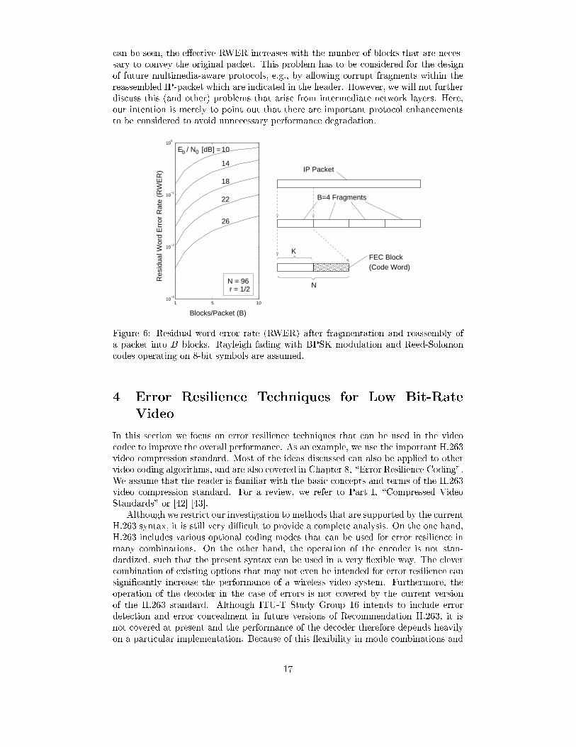
can be seen, the e�ective RWER increases with the number of blocks that are neces-sary to convey the original packet. This problem has to be considered for the designof future multimedia-aware protocols, e.g., by allowing corrupt fragments within thereassembled IP-packet which are indicated in the header. However, we will not furtherdiscuss this (and other) problems that arise from intermediate network layers. Here,our intention is merely to point out that there are important protocol enhancementsto be considered to avoid unnecessary performance degradation.
1 5 1010
−3
10−2
10−1
100
10
22
K
Res
idua
l Wor
d E
rror
Rat
e (R
WE
R)
26
18
14
Blocks/Packet (B)
(Code Word)
N
B=4 Fragments
FEC Block
IP Packet
E / N [dB] =b
N = 96r = 1/2
0
������������������
������������������
Figure 6: Residual word error rate (RWER) after fragmentation and reassembly ofa packet into B blocks. Rayleigh fading with BPSK modulation and Reed-Solomoncodes operating on 8-bit symbols are assumed.
4 Error Resilience Techniques for Low Bit-Rate
Video
In this section we focus on error resilience techniques that can be used in the videocodec to improve the overall performance. As an example, we use the important H.263video compression standard. Most of the ideas discussed can also be applied to othervideo coding algorithms, and are also covered in Chapter 8, \Error Resilience Coding".We assume that the reader is familiar with the basic concepts and terms of the H.263video compression standard. For a review, we refer to Part I, \Compressed VideoStandards" or [42] [43].
Although we restrict our investigation to methods that are supported by the currentH.263 syntax, it is still very diÆcult to provide a complete analysis. On the one hand,H.263 includes various optional coding modes that can be used for error resilience inmany combinations. On the other hand, the operation of the encoder is not stan-dardized, such that the present syntax can be used in a very exible way. The clevercombination of existing options that may not even be intended for error resilience cansigni�cantly increase the performance of a wireless video system. Furthermore, theoperation of the decoder in the case of errors is not covered by the current versionof the H.263 standard. Although ITU-T Study Group 16 intends to include errordetection and error concealment in future versions of Recommendation H.263, it isnot covered at present and the performance of the decoder therefore depends heavilyon a particular implementation. Because of this exibility in mode combinations and
17
decoder operation, we can only discuss the most common and e�ective error resiliencetechniques.
4.1 Input Format and Rate Control
To achieve high compression, as required for the transmission over mobile radio chan-nels at low bit-rates, both the spatial resolution and the frame rate have to be reducedcompared to standard television pictures. We use the QCIF format (Quarter CommonIntermediate Format, 176�144 pixels) for our simulations, which is the most commoninput format at the considered range of bit-rates. As a typical frame rate we use 12.5fps (frames per second). Though a variable frame rate in the range of 5 to 15 fps maybe advantageous for subjective quality, we maintain a �xed rate of 12.5 fps to allow afair comparison between di�erent approaches based on PSNR values. Unless otherwisestated, we use sequences of 300 frames, i.e., 150 encoded frames covering a time periodof 12 seconds. Because the transmission over an unreliable channel introduces randomerrors, several simulations have to be performed for di�erent channel realizations toobtain averaged results according to (2). For each investigated error resilience tech-nique and parameter setting (FEC, Eb=N0, INTRA percentage, : : :) we use L = 30channel realizations.
We use a simple rate control in our simulations. Each frame is encoded with a�xed quantizer step size, which is adapted frame by frame to obtain a given targetbit rate. The adaptation of the quantizer step size is performed as follows. First themode decision is performed according to TMN5 [44] for the whole frame, and then theresulting prediction error is transformed and quantized with di�erent quantizer stepsizes. Finally, the value that minimizes the deviation from a desired bu�er fullnessis selected. This rate control reduces bu�er variations to an acceptable amount, andhence allows the transmission over a constant bit-rate channel with limited delay.In practice, more sophisticated quantizer control algorithms could be used that canfurther reduce bu�er uctuations at improved rate-distortion performance. For moreinformation on rate control algorithms and their implications on performance anddelay, see Chapter 9, \Variable Bit-Rate Video Coding."
4.2 Error Detection and Resynchronization
Transmission errors can be detected in a variety of ways. With FEC, errors canoften be detected with high reliability by the channel decoder, even if the correctioncapability of the code is exceeded. For example, in H.261 and H.263 an optional FECframing can be used to detect errors within a BCH(511,493) code word. If a packetprotocol stack such as IP is used, lower layers often provide error detection as a basicservice. For example, this is the case for the packet video standard ITU-T Rec. H.323(see Chapter 13, \Networked Video Systems Standards"). For our simulations, an RScode is used with a block size of 88 bytes. This block size corresponds to the averagesize of one GOB for the given input format (QCIF, 12.5 fps) and bit-rate (80 kbps).The packetization delay in the order of a GOB can be neglected, even for low-latencyapplications.
In some transmission systems, reliability information can be obtained for each re-ceived bit when the receiver provides channel state information, or when the channeldecoder provides reliability information [45] [46]. This information is then passed onto the video decoder. In addition, the video decoder itself can detect transmission er-rors. The video bit-stream contains some residual redundancy, such that violations ofsyntactic or semantic constraints will usually occur quickly after a loss of synchroniza-tion [13] [47] [48], [49]. For example, the decoder might not �nd a matching variablelength code (VLC) word in the code table (a syntax violation), or detect that the
18
decoded motion vectors, DCT coeÆcients, or quantizer step-sizes exceed their permis-sible range (semantic violations). Additionally, the accumulated run that is used toplace DCT coeÆcients into an 8�8 block might exceed 64, or the number of MBs ina GOB might be too small or too large. Especially for severe errors, the detectioncan further be supported by localizing visual artifacts that are unlikely to appear innatural video signals. However, these inherent error detection capabilities of a videodecoder have a limited reliability and cannot exactly localize errors. Usually, severalerroneous code words are processed by the video decoder before syntactic or semanticconstraints are violated, and the distance between error location and error detectioncan vary signi�cantly. Therefore, external error detection mechanisms, such as FECframing, should be used if available.
A more diÆcult problem than error detection is resynchronization after a detectederror. Because the multiplexed video bit-stream consists of VLC words, a single biterror often causes a loss of synchronization and a series of erroneous code words atthe decoder. Residual redundancy in non-compact VLCs can be used to design self-synchronizing codes, such that valid symbols may be obtained again after some slippage[50]. However, even if resynchronization is regained quickly, the appropriate location ofthe decoded information within the video frame is no longer known, since the numberof missing symbols cannot be determined. Moreover, the subsequent code words areuseless if the information is encoded di�erentially, as it is often the case, e.g., for motionvectors. The common solution to this problem is to insert unique synchronizationcode words into the bit-stream in regular intervals, usually followed by a block of\header" bits. Since any conditional encoding across the resynchronization point mustbe avoided, the header provides anchor values, e.g., for absolute location in the imageor current quantizer step size. Although the length of the synchronization code wordcan be minimized [51], relatively long synchronization code words are used in practiceto reduce the probability of accidental emulation in the bitstream.
Recently, more advanced techniques for resynchronization have been developed inthe context of MPEG-4 and H.263++. Among several error resilience tools, data par-titioning has been shown to be e�ective [13]. Especially when combined with reversiblevariable length coding (RVLC), which allows bit-streams to be decoded in either for-ward or reverse direction, the number of symbols that have to be discarded can bereduced signi�cantly. Because RVLCs can be matched well to the statistics of imageand video data, only a small penalty in coding eÆciency is incurred [52] [53]. A recentlyproposed technique can even approach the eÆciency of Hu�man codes by combining apre�x and suÆx code word stream by delayed XORing [54]. Another elegant techniquethat is not part of any current video coding standard has been proposed by Redmilland Kingsbury as Error-Resilient Entropy Coding (EREC) [55]. Similar to data par-titioning, a re-ordering of the bit-stream is involved. Instead of clustering all symbolsof the same type into one partition, EREC re-organizes VLC image blocks such thateach block starts at a known position within the bit-stream and the most importantinformation is closest to these synchronization points. More information on RVLCsand EREC can also be found in Chapter 8, \Error Resilience Coding".
Considering H.263, the most basic way of improving resynchronization is to usemore GOB-headers, which can be inserted optionally as resynchronization points atthe beginning of each GOB. In QCIF format, 9 GOBs are encoded which consist of 11macroblocks in one row. Except for the �rst GOB that always starts with the picture-header all GOBs may or may not include a GOB-header. The unique synchronizationword that is used in H.263 as a preamble for the GOB-header consists of 16 consecutive0-bits followed by a 1-bit (\00000000000000001"). The encoding of anchor values in theheader that follows the synch word require 12 bits, such that the total number of bitsfor a GOB-header is 29. In addition to this overhead, the rate-distortion performanceis further reduced by less e�ective prediction of motion vectors. However, this reduced
19

coding eÆciency is usually well compensated by improved error resilience as will beshown below.
Because all information between two resynchronization points can be used inde-pendently from previous information in the same frame, the corresponding set of mac-roblocks is often used as the basic unit for decoding. In the following we use the termslice to refer to this set of macroblocks. In the baseline mode of H.263, a slice alwayscorresponds to an integer number of GOBs because the placement of resynchroniza-tion points is restricted to the start of a GOB. However, in the slice structure modeof H.263 (Annex K) the placement of resynchronization points is allowed after eachmacroblock providing increased exibility. On the one hand, it is possible to furtherincrease the number of resynchronization points per frame, which is restricted to 9 inQCIF baseline mode. On the other hand, it is possible to adapt the size of slices to thesize of packets or FEC blocks. When Annex K is enabled, GOB-headers are replacedby Slice-headers with very similar functionality but slightly increased overhead (34bits including synch word).
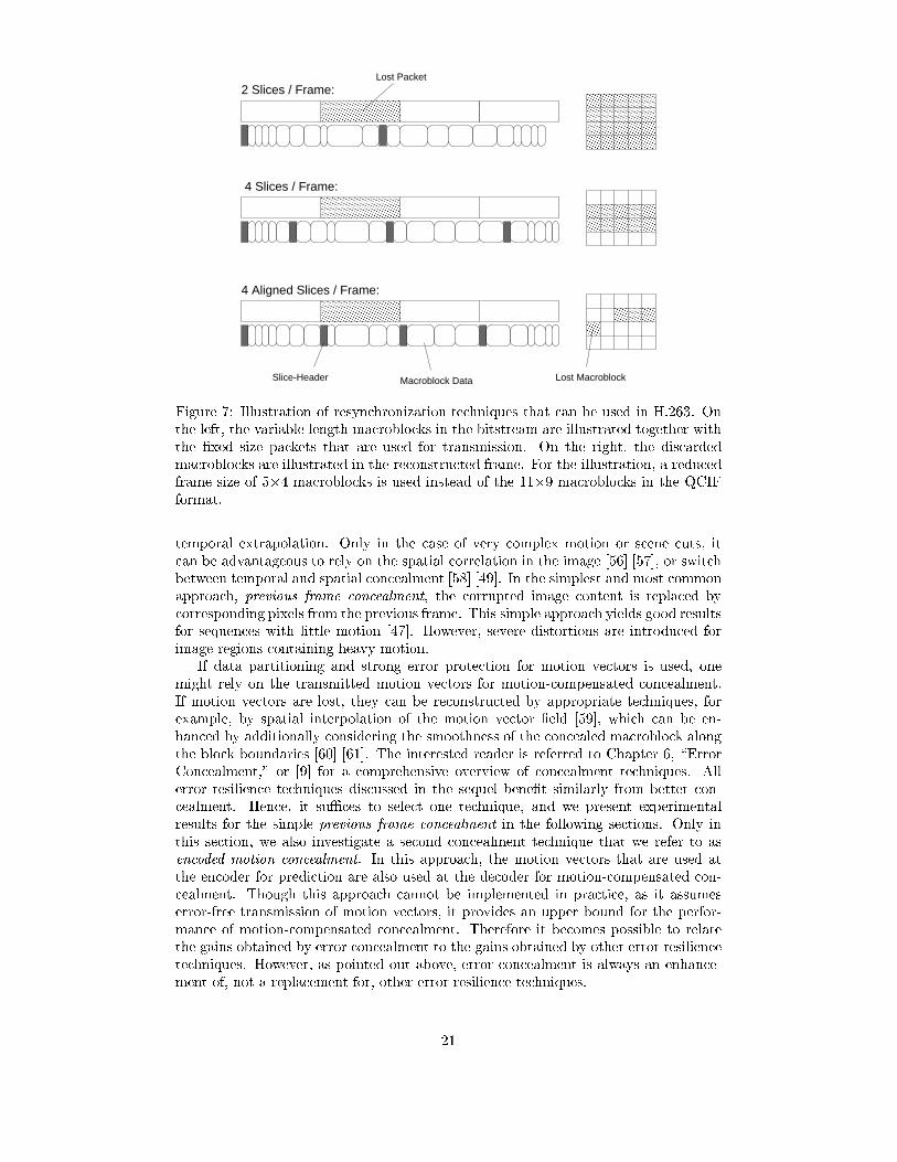
Typically, if a transmission error is detected within a slice, it is discarded entirelyand error concealment is invoked for all its macroblocks. This approach is also takenthroughout this chapter for the experiments. Because we employ an FEC framingwith �xed block size, several slices may overlap with a single FEC block. In this case,the decoder invokes error concealment for each slice that overlaps with the corruptedblock. To reduce the number of discarded macroblocks it is therefore particularlyimportant to reduce the size of slices. In the slice structure mode, the overlap of anFEC blocks with two adjacent slices can be avoided by starting a new slice at thebeginning of the next block. This results in �xed length \video packets" that includea variable number of macroblocks. In MPEG-4, this technique has already proven tobe e�ective. However, this ideal packetization requires a close interworking betweensource and channel coding, which may be diÆcult in some situations. For example, in acall through a gateway, the source coding is done in a terminal, while the packetizationis done in the gateway. Fig. 7 schematically illustrates the advantage of using anincreased number of slices per frame and the additional advantage of alignment withpackets.
Finally, Fig. 8 illustrates the performance of H.263 using di�erent numbers of synchwords per frame. The slice structure mode is not enabled, but the number of synchwords is increased by inserting additional GOB-headers. Discarded macroblocks areconcealed by simply copying the corresponding image data from the reference frame(see Section 4.3). From the left side of Fig. 8 it can be seen that the maximum numberof headers (one picture header and 8 GOB headers) is always advantageous for Eb=N0
= 26 dB. Though the loss in picture quality �PSNR is only slightly improved byusing more than 5 synch words per frame, the increased overhead for 9 synch wordsis still justi�ed. However, it can be expected that a signi�cantly higher number, aswould be possible using Annex K, would �nally result in a reduced performance. InChapter 8, \Error Resilient Coding", the optimum amount and location of synch wordsis investigated for the slice structure mode. The right side of Fig. 8 that the loss inpicture quality when a PSNR of 36 dB is required at the encoder output. For thewhole range of investigated Eb=N0 values, 9 synch words/frame provide the optimumperformance. For all other simulations in this chapter we will therefore use GOB-headers for each GOB.
4.3 Error Concealment
The severeness of residual errors can be reduced if error concealment techniques areemployed to hide visible distortion as well as possible. Since typically an entire GOB isa�ected (i.e., 16 successive luminance lines), spatial interpolation is less eÆcient than
20
���������
���������
���������
���������
������
������
������
������
��������������������������������
��������������������������������
������
������
����������������������������������������������������������������������������������������
����������������������������������������������������������������������������������������
��������������������������������
��������������������������������
���������
���������
������
������
������
������
������
������
���������
���������
���������
���������
��������������������������������
��������������������������������
������
������
������
������
������
������
4 Aligned Slices / Frame:
4 Slices / Frame:
2 Slices / Frame:Lost Packet
Lost MacroblockSlice-Header Macroblock Data
Figure 7: Illustration of resynchronization techniques that can be used in H.263. Onthe left, the variable length macroblocks in the bitstream are illustrated together withthe �xed size packets that are used for transmission. On the right, the discardedmacroblocks are illustrated in the reconstructed frame. For the illustration, a reducedframe size of 5�4 macroblocks is used instead of the 11�9 macroblocks in the QCIFformat.
temporal extrapolation. Only in the case of very complex motion or scene cuts, itcan be advantageous to rely on the spatial correlation in the image [56] [57], or switchbetween temporal and spatial concealment [58] [49]. In the simplest and most commonapproach, previous frame concealment, the corrupted image content is replaced bycorresponding pixels from the previous frame. This simple approach yields good resultsfor sequences with little motion [47]. However, severe distortions are introduced forimage regions containing heavy motion.
If data partitioning and strong error protection for motion vectors is used, onemight rely on the transmitted motion vectors for motion-compensated concealment.If motion vectors are lost, they can be reconstructed by appropriate techniques, forexample, by spatial interpolation of the motion vector �eld [59], which can be en-hanced by additionally considering the smoothness of the concealed macroblock alongthe block boundaries [60] [61]. The interested reader is referred to Chapter 6, \ErrorConcealment," or [9] for a comprehensive overview of concealment techniques. Allerror resilience techniques discussed in the sequel bene�t similarly from better con-cealment. Hence, it suÆces to select one technique, and we present experimentalresults for the simple previous frame concealment in the following sections. Only inthis section, we also investigate a second concealment technique that we refer to asencoded motion concealment. In this approach, the motion vectors that are used atthe encoder for prediction are also used at the decoder for motion-compensated con-cealment. Though this approach cannot be implemented in practice, as it assumeserror-free transmission of motion vectors, it provides an upper bound for the perfor-mance of motion-compensated concealment. Therefore it becomes possible to relatethe gains obtained by error concealment to the gains obtained by other error resiliencetechniques. However, as pointed out above, error concealment is always an enhance-ment of, not a replacement for, other error resilience techniques.
21
34.5 35 35.5 36 36.5 37 37.5 38 38.5 390
1
2
3
4
5
6
7
8
1
3
5
9
E / N = 26 dB
synch words / frame =
0
ePSNR [dB]
PS
NR
[dB
]∆
b
10 12 14 16 18 20 22 24 26 28 300
2
4
6
8
10
12
14
5= sync words / frame
913
E / N [dB]
PS
NR
[dB
]∆
ePSNR = 36 dB
b 0
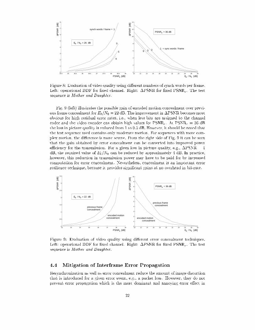
Figure 8: Evaluation of video quality using di�erent numbers of synch words per frame.Left: operational DDF for �xed channel. Right: �PSNR for �xed PSNRe. The testsequence is Mother and Daughter.
Fig. 9 (left) illustrates the possible gain of encoded motion concealment over previ-ous frame concealment for Eb=N0 = 22 dB. The improvement in �PSNR becomes mostobvious for high residual error rates, i.e., when less bits are assigned to the channelcodec and the video encoder can obtain high values for PSNRe. At PSNRe = 36 dBthe loss in picture quality is reduced from 1 to 0.5 dB. However, it should be noted thatthe test sequence used contains only moderate motion. For sequences with more com-plex motion, the di�erence is more severe. From the right side of Fig. 9 it can be seenthat the gain obtained by error concealment can be converted into improved powereÆciency for the transmission. For a given loss in picture quality, e.g., �PSNR = 1dB, the required value of Eb=N0 can be reduced by approximately 4 dB. In practice,however, this reduction in transmission power may have to be paid for by increasedcomputation for error concealment. Nevertheless, concealment is an important errorresilience technique, because it provides signi�cant gains at no overhead in bit-rate.
32 33 34 35 36 37 38 390
0.5
1
1.5
2
2.5
3
3.5
0E / N = 22 dB
previous frameconcealment
concealmentencoded motion
b
ePSNR [dB]
PS
NR
[dB
]∆
10 12 14 16 18 20 22 24 26 28 300
1
2
3
4
5
6
7
8
9
10
E / N [dB]
concealment
previous frameconcealment
encoded motion
0
ePSNR = 36 dB
PS
NR
[dB
]∆
b
Figure 9: Evaluation of video quality using di�erent error concealment techniques.Left: operational DDF for �xed channel. Right: �PSNR for �xed PSNRe. The testsequence is Mother and Daughter.
4.4 Mitigation of Interframe Error Propagation
Resynchronization as well as error concealment reduce the amount of image distortionthat is introduced for a given error event, e.g., a packet loss. However, they do notprevent error propagation which is the most dominant and annoying error e�ect in
22
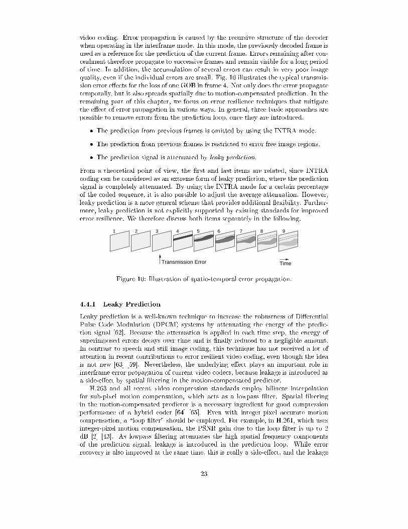
video coding. Error propagation is caused by the recursive structure of the decoderwhen operating in the interframe mode. In this mode, the previously decoded frame isused as a reference for the prediction of the current frame. Errors remaining after con-cealment therefore propagate to successive frames and remain visible for a long periodof time. In addition, the accumulation of several errors can result in very poor imagequality, even if the individual errors are small. Fig. 10 illustrates the typical transmis-sion error e�ects for the loss of one GOB in frame 4. Not only does the error propagatetemporally, but it also spreads spatially due to motion-compensated prediction. In theremaining part of this chapter, we focus on error resilience techniques that mitigatethe e�ect of error propagation in various ways. In general, three basic approaches arepossible to remove errors from the prediction loop, once they are introduced.
� The prediction from previous frames is omitted by using the INTRA mode.
� The prediction from previous frames is restricted to error free image regions.
� The prediction signal is attenuated by leaky prediction.
From a theoretical point of view, the �rst and last items are related, since INTRAcoding can be considered as an extreme form of leaky prediction, where the predictionsignal is completely attenuated. By using the INTRA mode for a certain percentageof the coded sequence, it is also possible to adjust the average attenuation. However,leaky prediction is a more general scheme that provides additional exibility. Further-more, leaky prediction is not explicitly supported by existing standards for improvederror resilience. We therefore discuss both items separately in the following.
9
Transmission Error Time
1 2 3 4 5 6 7 8
Figure 10: Illustration of spatio-temporal error propagation.
4.4.1 Leaky Prediction
Leaky prediction is a well-known technique to increase the robustness of Di�erentialPulse Code Modulation (DPCM) systems by attenuating the energy of the predic-tion signal [62]. Because the attenuation is applied in each time step, the energy ofsuperimposed errors decays over time and is �nally reduced to a negligible amount.In contrast to speech and still image coding, this technique has not received a lot ofattention in recent contributions to error resilient video coding, even though the ideais not new [63] [59]. Nevertheless, the underlying e�ect plays an important role ininterframe error propagation of current video codecs, because leakage is introduced asa side-e�ect by spatial �ltering in the motion-compensated predictor.
H.263 and all recent video compression standards employ bilinear interpolationfor sub-pixel motion compensation, which acts as a lowpass �lter. Spatial �lteringin the motion-compensated predictor is a necessary ingredient for good compressionperformance of a hybrid coder [64] [65]. Even with integer-pixel accurate motioncompensation, a \loop �lter" should be employed. For example, in H.261, which usesinteger-pixel motion compensation, the PSNR gain due to the loop �lter is up to 2dB [2] [43]. As lowpass �ltering attenuates the high spatial frequency componentsof the prediction signal, leakage is introduced in the prediction loop. While errorrecovery is also improved at the same time, this is really a side-e�ect, and the leakage
23
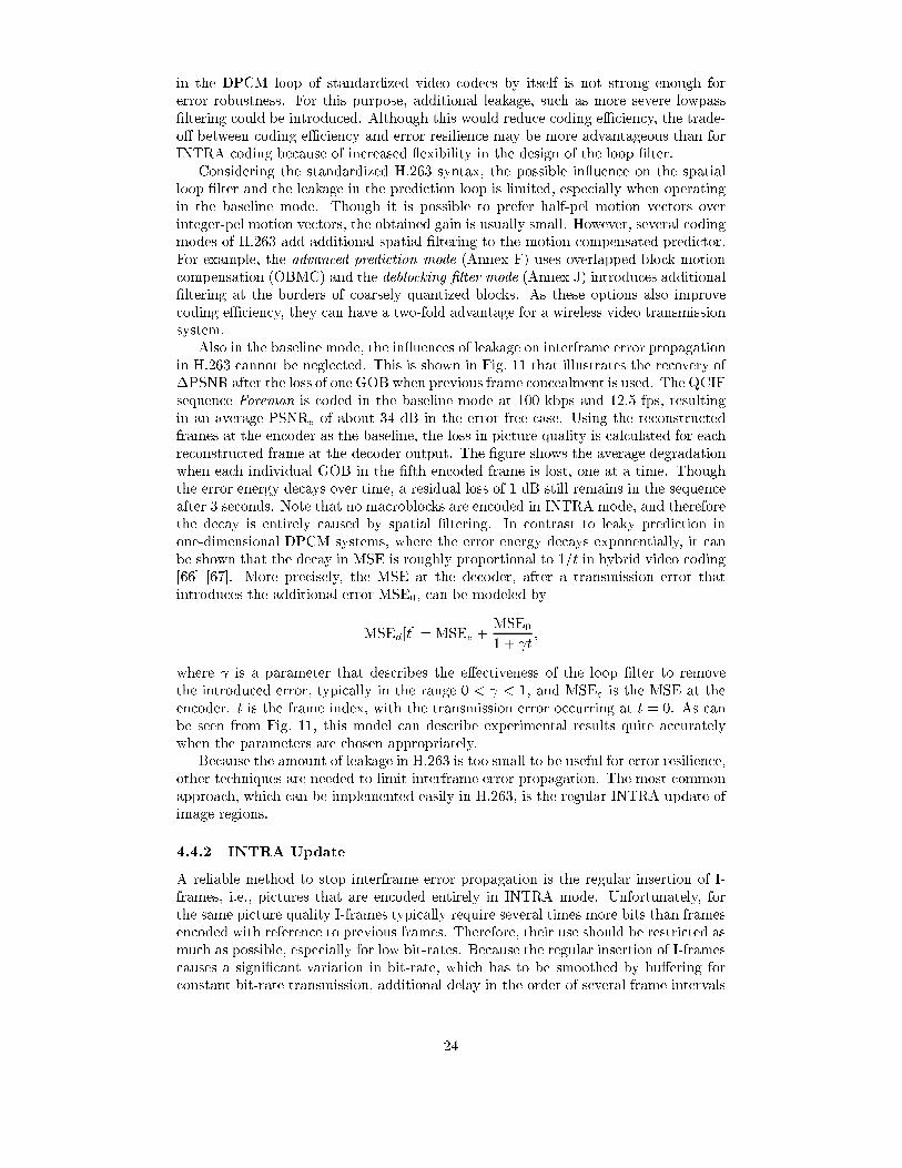
in the DPCM loop of standardized video codecs by itself is not strong enough forerror robustness. For this purpose, additional leakage, such as more severe lowpass�ltering could be introduced. Although this would reduce coding eÆciency, the trade-o� between coding eÆciency and error resilience may be more advantageous than forINTRA coding because of increased exibility in the design of the loop �lter.
Considering the standardized H.263 syntax, the possible in uence on the spatialloop �lter and the leakage in the prediction loop is limited, especially when operatingin the baseline mode. Though it is possible to prefer half-pel motion vectors overinteger-pel motion vectors, the obtained gain is usually small. However, several codingmodes of H.263 add additional spatial �ltering to the motion-compensated predictor.For example, the advanced prediction mode (Annex F) uses overlapped block motioncompensation (OBMC) and the deblocking �lter mode (Annex J) introduces additional�ltering at the borders of coarsely quantized blocks. As these options also improvecoding eÆciency, they can have a two-fold advantage for a wireless video transmissionsystem.
Also in the baseline mode, the in uences of leakage on interframe error propagationin H.263 cannot be neglected. This is shown in Fig. 11 that illustrates the recovery of�PSNR after the loss of one GOB when previous frame concealment is used. The QCIFsequence Foreman is coded in the baseline mode at 100 kbps and 12.5 fps, resultingin an average PSNRe of about 34 dB in the error-free case. Using the reconstructedframes at the encoder as the baseline, the loss in picture quality is calculated for eachreconstructed frame at the decoder output. The �gure shows the average degradationwhen each individual GOB in the �fth encoded frame is lost, one at a time. Thoughthe error energy decays over time, a residual loss of 1 dB still remains in the sequenceafter 3 seconds. Note that no macroblocks are encoded in INTRA mode, and thereforethe decay is entirely caused by spatial �ltering. In contrast to leaky prediction inone-dimensional DPCM systems, where the error energy decays exponentially, it canbe shown that the decay in MSE is roughly proportional to 1=t in hybrid video coding[66] [67]. More precisely, the MSE at the decoder, after a transmission error thatintroduces the additional error MSE0, can be modeled by
MSEd[t] = MSEe +MSE01 + t
;
where is a parameter that describes the e�ectiveness of the loop �lter to removethe introduced error, typically in the range 0 < < 1, and MSEe is the MSE at theencoder. t is the frame index, with the transmission error occurring at t = 0. As canbe seen from Fig. 11, this model can describe experimental results quite accuratelywhen the parameters are chosen appropriately.
Because the amount of leakage in H.263 is too small to be useful for error resilience,other techniques are needed to limit interframe error propagation. The most commonapproach, which can be implemented easily in H.263, is the regular INTRA update ofimage regions.
4.4.2 INTRA Update
A reliable method to stop interframe error propagation is the regular insertion of I-frames, i.e., pictures that are encoded entirely in INTRA mode. Unfortunately, forthe same picture quality I-frames typically require several times more bits than framesencoded with reference to previous frames. Therefore, their use should be restricted asmuch as possible, especially for low bit-rates. Because the regular insertion of I-framescauses a signi�cant variation in bit-rate, which has to be smoothed by bu�ering forconstant bit-rate transmission, additional delay in the order of several frame intervals
24

0 1 2 3 4 5 6 70
0.5
1
1.5
2
2.5
3
3.5
4
4.5
Model
time [s]
Simulation∆PS
NR
[dB
]
Figure 11: Recovery of picture quality after previous frame concealment of one GOB.Leakage introduced by spatial �ltering is the cause of this recovery.
is introduced. To avoid this, INTRA coding can be distributed over several frames,such that a certain percentage of each frame is updated.
The correct choice of the INTRA percentage is a non-trivial issue that is in uencedby the error characteristic of the channel, the decoder implementation, and the encodedvideo sequence. Obviously there is a trade-o� to be considered. On the one hand, anincreased percentage helps to reduce interframe error propagation. On the other hand,the coding eÆciency is reduced at the same time. Besides the appropriate choice ofINTRA percentage, there is great exibility in the update pattern. Because the INTRAmode can be selected by the coding control of the encoder for each macroblock, it isup to the implementor to decide on the most e�ective scheme. For example, a certainnumber of INTRA coded macroblocks can be distributed randomly within a frame orclustered together in a small region.
In a very common scheme, which is also requested in H.263, each macroblock isassigned a counter that is incremented if the macroblock is encoded in interframemode. If the counter reaches a threshold T , the macroblock is encoded in INTRAmode and the counter is reset to zero. By assigning a di�erent initial o�set to eachmacroblock, the update time of macroblocks can be distributed uniformly within theINTRA update interval T . However, the main reason for INTRA updates in H.263is the IDCT mismatch rather than improved error resilience. IDCT mismatch maycause an accumulation of errors in the prediction loop if the encoder and decoder useslightly di�erent implementations of the inverse DCT. Because this e�ect is usuallysmall, a rather long update interval is suÆcient. The H.263 standard requests a min-imum value of T = 132. However, lower values are advantageous for error resilience.In our simulations we use a very similar update scheme and refer to it as periodicINTRA update. The only di�erence is that we also increment the counter for skippedmacroblocks to guarantee a regular update of all image regions.
Other update schemes have been proposed in the literature to further improvethe e�ectiveness of INTRA coding. In [59] and [68] it has been shown that it isadvantageous to consider the image content when deciding on the frequency of INTRAcoding. For example, image regions that cannot be concealed very well should berefreshed more often, whereas no INTRA coding is necessary for completely staticbackground. This idea can also be included in a rate{distortion optimized encodingframework as proposed in [69] and [26], which is also discussed in more detail inChapter 8, \Error Resilience Coding". Finally, di�erent INTRA coding patterns,such as 9 randomly distributed macroblocks, 1�9, or 3�3 groups of macroblocks have
25

been compared by Zhu and Kerofsky [25]. Though the shape of di�erent patternsslightly in uences the performance, the selection of the correct INTRA percentagehas a signi�cantly higher in uence. We employ the periodic INTRA update schemedescribed above.
The results for the simulated transmission over a Rayleigh channel are presentedin Fig. 12. From the DDF (left) it can seen that a choice of 6 % INTRA macroblocksresults in the optimum performance for the Rayleigh fading channel at Eb=N0 = 18dB. Note that lower as well as higher percentages reduce the performance at a givenvalue of PSNRe. In particular, the loss in �PSNR is as much as 4 dB when comparing6 % INTRA vs. 0 % INTRA at PSNRe = 36 dB. The right side of Fig. 12 shows that6 % INTRA macroblocks is also the optimum choice for the whole range of channelconditions that are investigated. Therefore we will use this number in all followingsimulations. In fact, the results that we presented in the previous sections also usethe described INTRA update scheme and 6 % INTRA macroblocks. Note, however,that the optimum INTRA percentage depends on the encoded sequence as well as theRWER and the concealment algorithm employed. In practice, it is therefore diÆcultto select the correct INTRA percentage.
28 30 32 34 36 38 400
2
4
6
8
10
12
14
16
0
33
22
11
% INTRA =
b 0E / N = 18 dB
6
ePSNR [dB]
PS
NR
[dB
]∆
3
1
10 12 14 16 18 20 22 24 26 28 300
2
4
6
8
10
12
6
11 31
0
% INTRA =
PS
NR
[dB
]∆
ePSNR = 36 dB
b 0E / N [dB]
Figure 12: Evaluation of video quality using di�erent amounts of INTRA coded mac-roblocks. Left: operational DDF for �xed channel. Right: �PSNR for �xed PSNRe.The test sequence is Mother and Daughter.
4.4.3 Error Con�nement
Leaky prediction and INTRA coding mainly address the problem of temporal errorpropagation. However, interframe error propagation also results in a spatial errorspreading, as illustrated in Fig. 10. Due to motion-compensated prediction, errorsmay move from their original location to other parts of the frame and may even spreadover the whole image. In some situations it is easier to combat the error by con�ningit to a well-de�ned sub-region of the frame. This can be achieved by restricting therange of motion vectors, such that no information outside the sub-region is used forprediction. In e�ect, the video sequence is partitioned into sub-videos that can bedecoded independently.
Though the restriction of motion vectors could be guaranteed by the coding controlof the encoder without any additional changes to the syntax, H.263 o�ers an optionalmode for such a sub-video technique to allow a clearer and easier implementation.The Independent Segment Decoding mode (ISD mode) is described in Annex R ofH.263. It can also be combined with the Slice Structure mode, but we restrict thediscussion to the case in which a segment is identical to a GOB (assuming GOB-headersfor each GOB). In the ISD mode, each GOB is encoded as an individual sub-video
26
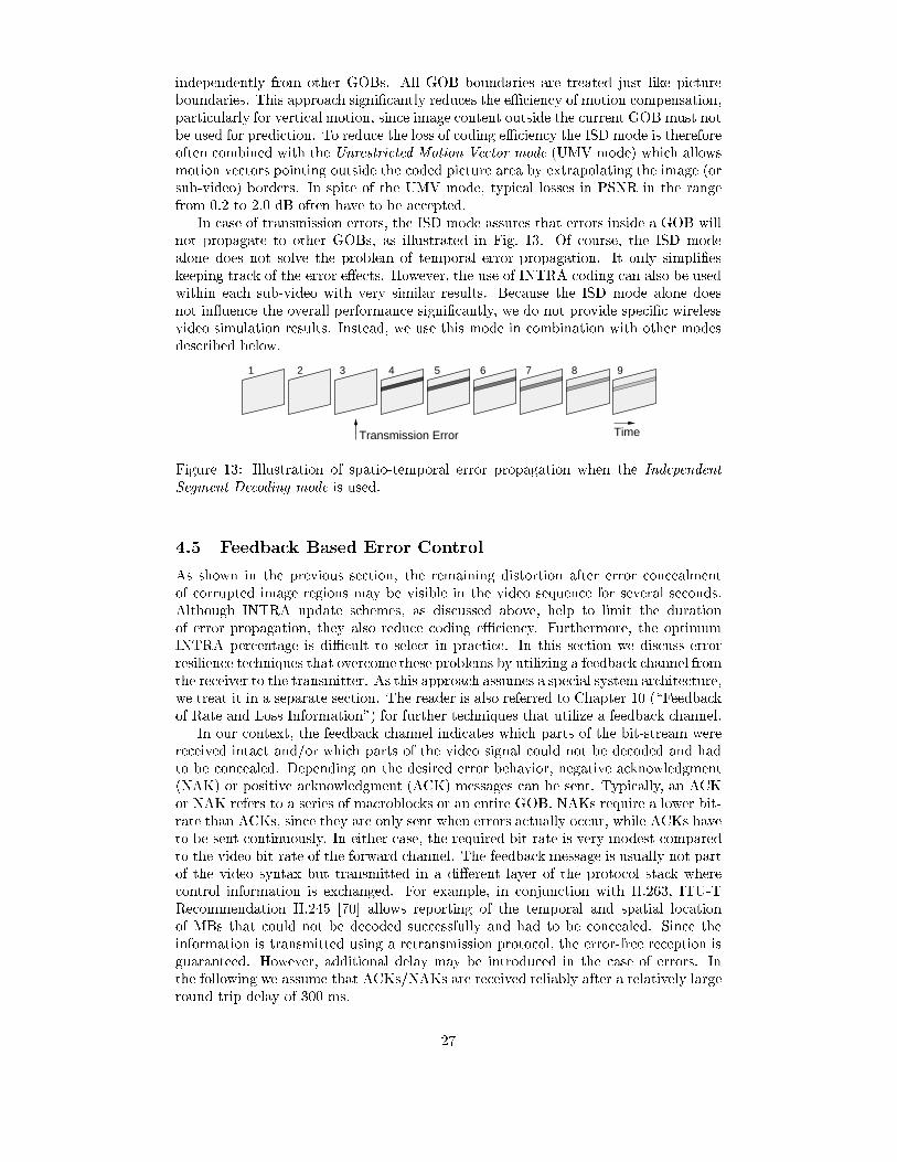
independently from other GOBs. All GOB boundaries are treated just like pictureboundaries. This approach signi�cantly reduces the eÆciency of motion compensation,particularly for vertical motion, since image content outside the current GOB must notbe used for prediction. To reduce the loss of coding eÆciency the ISD mode is thereforeoften combined with the Unrestricted Motion Vector mode (UMV mode) which allowsmotion vectors pointing outside the coded picture area by extrapolating the image (orsub-video) borders. In spite of the UMV mode, typical losses in PSNR in the rangefrom 0.2 to 2.0 dB often have to be accepted.
In case of transmission errors, the ISD mode assures that errors inside a GOB willnot propagate to other GOBs, as illustrated in Fig. 13. Of course, the ISD modealone does not solve the problem of temporal error propagation. It only simpli�eskeeping track of the error e�ects. However, the use of INTRA coding can also be usedwithin each sub-video with very similar results. Because the ISD mode alone doesnot in uence the overall performance signi�cantly, we do not provide speci�c wirelessvideo simulation results. Instead, we use this mode in combination with other modesdescribed below.
9
Transmission Error Time
1 2 3 4 5 6 7 8
Figure 13: Illustration of spatio-temporal error propagation when the IndependentSegment Decoding mode is used.
4.5 Feedback Based Error Control
As shown in the previous section, the remaining distortion after error concealmentof corrupted image regions may be visible in the video sequence for several seconds.Although INTRA update schemes, as discussed above, help to limit the durationof error propagation, they also reduce coding eÆciency. Furthermore, the optimumINTRA percentage is diÆcult to select in practice. In this section we discuss errorresilience techniques that overcome these problems by utilizing a feedback channel fromthe receiver to the transmitter. As this approach assumes a special system architecture,we treat it in a separate section. The reader is also referred to Chapter 10 (\Feedbackof Rate and Loss Information") for further techniques that utilize a feedback channel.
In our context, the feedback channel indicates which parts of the bit-stream werereceived intact and/or which parts of the video signal could not be decoded and hadto be concealed. Depending on the desired error behavior, negative acknowledgment(NAK) or positive acknowledgment (ACK) messages can be sent. Typically, an ACKor NAK refers to a series of macroblocks or an entire GOB. NAKs require a lower bit-rate than ACKs, since they are only sent when errors actually occur, while ACKs haveto be sent continuously. In either case, the required bit-rate is very modest comparedto the video bit-rate of the forward channel. The feedback message is usually not partof the video syntax but transmitted in a di�erent layer of the protocol stack wherecontrol information is exchanged. For example, in conjunction with H.263, ITU-TRecommendation H.245 [70] allows reporting of the temporal and spatial locationof MBs that could not be decoded successfully and had to be concealed. Since theinformation is transmitted using a retransmission protocol, the error-free reception isguaranteed. However, additional delay may be introduced in the case of errors. Inthe following we assume that ACKs/NAKs are received reliably after a relatively largeround trip delay of 300 ms.
27

4.5.1 Error Tracking
The Error Tracking approach uses the INTRA mode for selected MBs to stop in-terframe error propagation but limits its use to severely a�ected image regions only.During error-free transmission, the more e�ective INTER mode is used and the sys-tem therefore adapts e�ectively to varying channel conditions. This is accomplishedby processing the NAKs from a feedback channel in the coding control of the encoder.Based on the information of a NAK, the encoder can reconstruct the interframe errorpropagation at the decoder. The coding control of a forward-adaptive encoder canthen e�ectively stop interframe error propagation by avoiding the reference to severelya�ected MBs, e.g., by selecting the INTRA mode. If error concealment is successfuland the error of a certain MB is small, the encoder may decide that INTRA coding isnot necessary. For severe errors, a large number of MBs is encoded in INTRA mode,and the encoder may have to use a coarser quantizer to maintain a constant frame-rateand bit-rate. In this case, the overall picture quality at the source encoder decreaseswith a higher frequency of NAKs. Unlike retransmission techniques such as ARQ, Er-ror Tracking does not increase the delay between encoder and decoder. It is thereforeparticularly suitable for applications that require a short latency.
Fig. 14 illustrates Error Tracking for the same example as in Fig. 10. As soon asthe NAK is received with a system-dependent round-trip delay, the impaired MBs aredetermined and error propagation can be terminated by INTRA coding these MBs(frames 7-9). A longer round-trip delay just results in a later start of the error recov-ery. Note that it is necessary to track the shifting location of the errors to stop errorpropagation completely. In order to reconstruct the interframe error propagation thathas occurred at the decoder, the encoder could store its own output bit-stream anddecode it again, taking into account the reported loss of GOBs. While this approach isnot feasible for a real-time implementation, it illustrates that the encoder, in principle,possesses all the information necessary to reconstruct the spatio-temporal error propa-gation at the decoder, once the NAKs have been received. For a practical system, theinterframe error propagation has to be estimated with a low-complexity algorithm, asdescribed in [71], [14], and [15] for a macroblock-based coder, such as H.263. A worstcase estimate of error propagation that does not consider the severeness of errors isproposed by Wada [72].
TimeNAK(4)Transmission Error
1 2 3 4 5 6 7 8 9
INTRA coded MB
Figure 14: Illustration of spatio-temporal error propagation when Error Tracking isused.
The basic idea of the low-complexity algorithm is to carry out Error Trackingwith macroblock resolution rather than pixel resolution. This is suÆcient since theINTRA/INTER mode decision at the coder and the error concealment decision atthe decoder are carried out for entire MBs as well. In a cyclical bu�er for all MBsof the last several frames, the spatial overlap of MBs in successive frames due tomotion-compensated prediction is stored, along with the error energy that would beintroduced if concealment had to be used. If a NAK is received that indicates an errora few frames back, this error energy is \released" and \ripples" through the directedgraph of frame-to-frame dependencies to the macroblocks of the current frame. Sinceall calculations are carried out on the MB level, the computational burden and memory
28
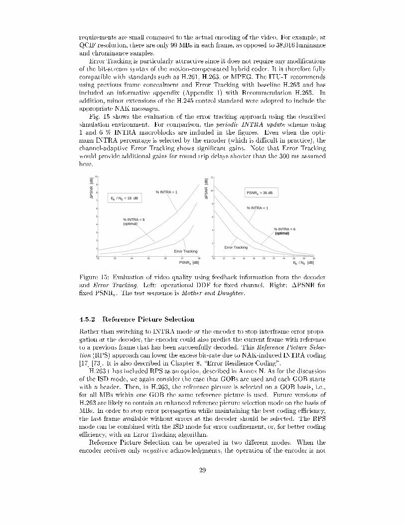
requirements are small compared to the actual encoding of the video. For example, atQCIF resolution, there are only 99 MBs in each frame, as opposed to 38,016 luminanceand chrominance samples.
Error Tracking is particularly attractive since it does not require any modi�cationsof the bit-stream syntax of the motion-compensated hybrid coder. It is therefore fullycompatible with standards such as H.261, H.263, or MPEG. The ITU-T recommendsusing previous frame concealment and Error Tracking with baseline H.263 and hasincluded an informative appendix (Appendix 1) with Recommendation H.263. Inaddition, minor extensions of the H.245 control standard were adopted to include theappropriate NAK messages.
Fig. 15 shows the evaluation of the error tracking approach using the describedsimulation environment. For comparison, the periodic INTRA update scheme using1 and 6 % INTRA macroblocks are included in the �gures. Even when the opti-mum INTRA percentage is selected by the encoder (which is diÆcult in practice), thechannel-adaptive Error Tracking shows signi�cant gains. Note that Error Trackingwould provide additional gains for round trip delays shorter than the 300 ms assumedhere.
32 33 34 35 36 37 380
1
2
3
4
5
6
7
8
9
10
Error Tracking
% INTRA = 1
% INTRA = 6(optimal)
ePSNR [dB]
PS
NR
[dB
]∆
b 0E / N = 18 dB
10 12 14 16 18 20 22 24 26 28 300
2
4
6
8
10
12
% INTRA = 6
% INTRA = 1
(optimal)(optimal)
Error Tracking
ePSNR = 36 dB
PS
NR
[dB
]∆
b 0E / N [dB]
Figure 15: Evaluation of video quality using feedback information from the decoderand Error Tracking. Left: operational DDF for �xed channel. Right: �PSNR for�xed PSNRe. The test sequence is Mother and Daughter.
4.5.2 Reference Picture Selection
Rather than switching to INTRA mode at the encoder to stop interframe error propa-gation at the decoder, the encoder could also predict the current frame with referenceto a previous frame that has been successfully decoded. This Reference Picture Selec-tion (RPS) approach can lower the excess bit-rate due to NAK-induced INTRA coding[17] [73]. It is also described in Chapter 8, \Error Resilience Coding".
H.263+ has included RPS as an option, described in Annex N. As for the discussionof the ISD mode, we again consider the case that GOBs are used and each GOB startswith a header. Then, in H.263, the reference picture is selected on a GOB basis, i.e.,for all MBs within one GOB the same reference picture is used. Future versions ofH.263 are likely to contain an enhanced reference picture selection mode on the basis ofMBs. In order to stop error propagation while maintaining the best coding eÆciency,the last frame available without errors at the decoder should be selected. The RPSmode can be combined with the ISD mode for error con�nement, or, for better codingeÆciency, with an Error Tracking algorithm.
Reference Picture Selection can be operated in two di�erent modes. When theencoder receives only negative acknowledgments, the operation of the encoder is not
29
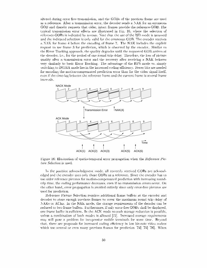
altered during error-free transmission, and the GOBs of the previous frame are usedas a reference. After a transmission error, the decoder sends a NAK for an erroneousGOB and thereby requests that older, intact frames provide the reference-GOB. Thetypical transmission error e�ects are illustrated in Fig. 16, where the selection ofreference-GOBs is indicated by arrows. Note that the use of the ISD mode is assumedand the indicated selection is only valid for the erroneous GOB. The encoder receivesa NAK for frame 4 before the encoding of frame 7. The NAK includes the explicitrequest to use frame 3 for prediction, which is observed by the encoder. Similar tothe Error Tracking approach, the quality degrades until the requested GOB arrives atthe decoder, i.e., for the period of one round trip delay. Therefore, the loss of picturequality after a transmission error and the recovery after receiving a NAK behavesvery similarly to basic Error Tracking. The advantage of the RPS mode vs. simplyswitching to INTRA mode lies in the increased coding eÆciency. Fewer bits are neededfor encoding the motion-compensated prediction error than for the video signal itself,even if the time-lag between the reference frame and the current frame is several frameintervals.
Transmission Error
NACK Mode1 2 3 4 5 6 7 8 9
NAK(4)
Time
ACK Mode1 6 7 8 95432
ACK(1) ACK(2) ACK(3) ACK(5) ACK(6)
Figure 16: Illustration of spatio-temporal error propagation when the Reference Pic-ture Selection is used.
In the positive acknowledgment mode, all correctly received GOBs are acknowl-edged and the encoder uses only those GOBs as a reference. Since the encoder has touse older reference pictures for motion-compensated prediction with increasing round-trip time, the coding performance decreases, even if no transmission errors occur. Onthe other hand, error propagation is avoided entirely since only error-free pictures areused for prediction.
Reference Picture Selection requires additional frame bu�ers at the encoder anddecoder to store enough previous frames to cover the maximum round trip delay ofNAKs or ACKs. In the NAK mode, the storage requirements of the decoder can bereduced to two frame bu�ers. Furthermore, if only error-free GOBs shall be displayed,one frame bu�er is suÆcient. In the ACK mode no such storage reduction is possible,unless a combination of both modes is allowed [73]. Increased storage requirementsmay still pose a problem for inexpensive mobile terminals for some time. Beyondthat, there are proposals for increased coding eÆciency in low bit-rate video codecswhich use several or even many previous frames for prediction [74] [75] [76]. When
30
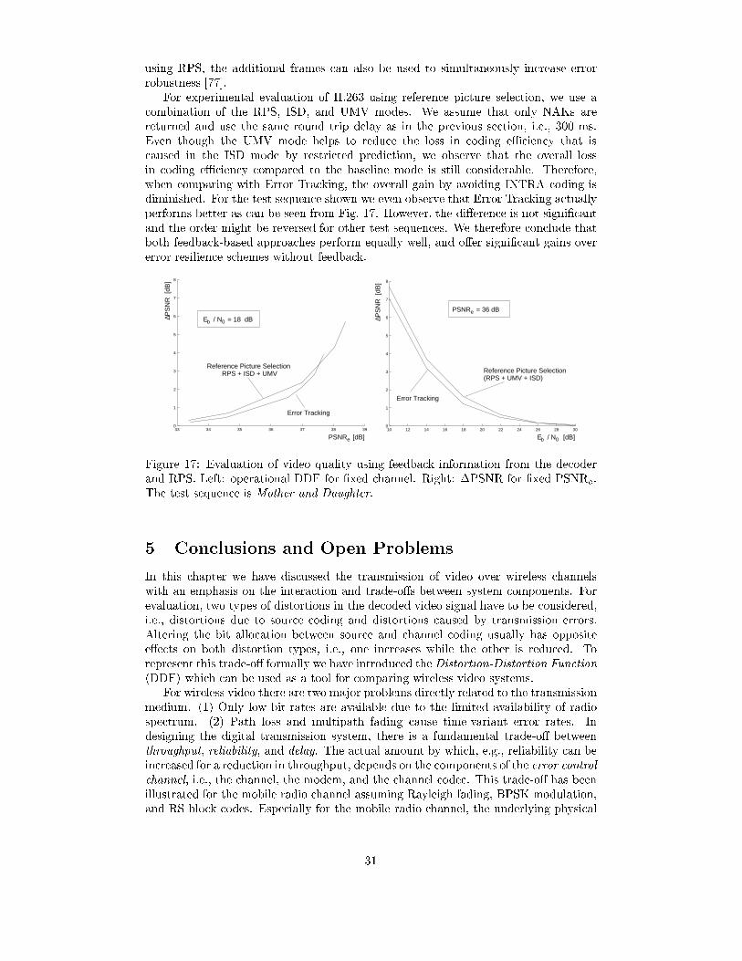
using RPS, the additional frames can also be used to simultaneously increase errorrobustness [77].
For experimental evaluation of H.263 using reference picture selection, we use acombination of the RPS, ISD, and UMV modes. We assume that only NAKs arereturned and use the same round trip delay as in the previous section, i.e., 300 ms.Even though the UMV mode helps to reduce the loss in coding eÆciency that iscaused in the ISD mode by restricted prediction, we observe that the overall lossin coding eÆciency compared to the baseline mode is still considerable. Therefore,when comparing with Error Tracking, the overall gain by avoiding INTRA coding isdiminished. For the test sequence shown we even observe that Error Tracking actuallyperforms better as can be seen from Fig. 17. However, the di�erence is not signi�cantand the order might be reversed for other test sequences. We therefore conclude thatboth feedback-based approaches perform equally well, and o�er signi�cant gains overerror resilience schemes without feedback.
33 34 35 36 37 38 390
1
2
3
4
5
6
7
8
Error Tracking
RPS + ISD + UMVReference Picture Selection
E / N = 18 dB
ePSNR [dB]
PS
NR
[dB
]∆
b 0
10 12 14 16 18 20 22 24 26 28 300
1
2
3
4
5
6
7
8
Error Tracking
Reference Picture Selection(RPS + UMV + ISD)
E / N [dB]
ePSNR = 36 dB
PS
NR
[dB
]∆
b 0
Figure 17: Evaluation of video quality using feedback information from the decoderand RPS. Left: operational DDF for �xed channel. Right: �PSNR for �xed PSNRe.The test sequence is Mother and Daughter.
5 Conclusions and Open Problems
In this chapter we have discussed the transmission of video over wireless channelswith an emphasis on the interaction and trade-o�s between system components. Forevaluation, two types of distortions in the decoded video signal have to be considered,i.e., distortions due to source coding and distortions caused by transmission errors.Altering the bit allocation between source and channel coding usually has oppositee�ects on both distortion types, i.e., one increases while the other is reduced. Torepresent this trade-o� formally we have introduced the Distortion-Distortion Function(DDF) which can be used as a tool for comparing wireless video systems.
For wireless video there are two major problems directly related to the transmissionmedium. (1) Only low bit-rates are available due to the limited availability of radiospectrum. (2) Path loss and multipath fading cause time-variant error rates. Indesigning the digital transmission system, there is a fundamental trade-o� betweenthroughput, reliability, and delay. The actual amount by which, e.g., reliability can beincreased for a reduction in throughput, depends on the components of the error controlchannel, i.e., the channel, the modem, and the channel codec. This trade-o� has beenillustrated for the mobile radio channel assuming Rayleigh fading, BPSK modulation,and RS block codes. Especially for the mobile radio channel, the underlying physical
31

mechanisms result in fundamental performance limits that require special measures inthe video codec as the \last line of defense".
In Section 4, we have discussed such measures for low bit-rate video, with particularemphasis on techniques with relevance to the H.263 Recommendation. These errorresilience techniques fall into two major categories { techniques that reduce the amountof introduced errors for a given error event (resynchronization, error concealment) andtechniques that limit interframe error propagation (leaky prediction, intra update). Thein uence of both categories on the overall performance can be signi�cant, as has beendemonstrated using operational DDFs. For example, for a given PSNR at the encoder,the loss in PSNR caused by transmission errors can be reduced from more than 10 dBto less than 2 dB when combining existing options appropriately.
Additional gains can be obtained when using channel-adaptive source coding. Theuse of feedback information on the source coding level is an eÆcient and elegant tech-nique for real-time multimedia communication over networks with heterogeneous QoS.Feedback schemes, such as Error Tracking or Reference Picture Selection, are suitablefor interactive, individual communications, but they have inherent limitations outsidethis domain. They are particularly powerful if the round-trip delay is short. If theround-trip delay increases they become less eÆcient and ultimately useless. Also, feed-back schemes rapidly deteriorate with increasing number of users. Their strength arepoint-to-point communications, and extensions to few users are possible at a loss inperformance.
There are several other approaches to error resilient video transmission that couldnot be covered in this chapter. In particular, data partitioning and scalable videocoding are of increased importance when feedback from the channel is not available.Instead, these approaches rely on priority mechanisms that are part of the networkcongestion management or provided implicitly through unequal error protection. Suchtechniques scale well with the number of users and are suitable for multicasting andbroadcasting. On the other hand, they are less eÆcient than feedback schemes forpoint-to-point communications. Hybrid techniques that combine the advantages ofchannel-adaptive source coding based on feedback and scalable coding are not knowntoday. Data partitioning and scalable video coding are covered in more detail inChapter 7, \Layered Coding". These techniques can be very e�ective in practice.
Also, so-called \multiple-description" coding (MDC) schemes tailored towardsgraceful degradation for randomly selected subsets of the bitstream are in their in-fancy today. The multiple-description coding problem in its simplest form attemptsto transmit a signal to three receivers, where receiver no. 1 receives a �rst bitstream,receiver no. 2 a second bitstream, and a third receiver both bitstreams. Such scenariosare directly relevant to broadcasting systems and transmission over erasure channelsor best e�ort networks. Since Shannon's separation principle for source and channelcoding does not hold, even the fundamental information theoretic performance lim-its for such schemes are unknown, let alone eÆcient algorithms that perform closeto these limits. The situation becomes even more complicated, if the in uence of adelay-constraint for real-time transmission is considered. More information on MDCis also included in Chapter 8, \Error Resilience Coding".
Besides the investigation of new coding schemes, the joint consideration of networkand application layers will play an important role in the future. The close interactionbetween these layers may seem to require a vertical system integration in a closednetwork architecture. However, exactly the opposite architecture is becoming moreand more important { horizontal integration with an IP-like spanning middle layerfor seamless communication across network boundaries. Any e�orts that require orassume closed network architectures are likely to be irrelevant in the future. Instead,the same interface/protocol will have to work across the wired and the wireless portionof the future multimedia network. There are two ways for multimedia applications to
32
evolve within an open system architecture. On the one hand, end-to-end transport anderror control for video/multimedia can be implemented in the terminals. On the otherhand, the IP protocol stack can be re�ned and extended to o�er additional services andfunctionalities that are required for eÆcient real-time transmission. Such multimedia-aware transport protocols need to consider the implications of wireless channels as theweakest link in the transmission chain. Otherwise, unnecessary performance degrada-tion cannot be avoided. Judging from current e�orts, both possibilities { end-to-enderror control and multimedia-aware extensions of current transport protocols { willcontinue to evolve and contribute to the ultimate success of wireless video.
References
[1] J. Uddenfeldt, \Digital Cellular - Its Roots and Its Future," Special Issue onMobile Radio Centennial, Proceedings of the IEEE, vol. 86, no. 7, pp. 1319-1324,July 1998.
[2] B. Girod, N. F�arber, and E. Steinbach, \Performance of the H.263 Video Compres-sion Standard," Journal of VLSI Signal Processing: Systems for Signal, Image,and Video Technology, vol. 17, pp. 101-111, Nov. 1997.
[3] E. Berruto, M. Gudmonson, R. Menolascino, W. Mohr, and M. Pizarroso, \Re-search Activities on UMTS Radio Interface, Network Architectures, and Plan-ning," IEEE Commun. Mag., vol. 36, no. 2, pp. 82-95, Feb. 1998.
[4] D. Grillo (ed.), Special Section on Third-Generation Mobile Systems in Europe,IEEE Personal Commun. Mag., vol. 5, no. 2, pp. 5-38, April 1998.
[5] P. Bahl and B. Girod (eds.), Special Section on Wireless Video, IEEE Commun.Mag., vol. 36, no. 6, pp. 92-151, June 1998.
[6] S. Lin, D.J. Costello, and M.J. Miller, \Automatic repeat error control schemes,"IEEE Commun. Mag., vol. 22, pp. 5-17, Dec. 1984.
[7] A. Heron and N. MacDonald, \Video transmission over a radio link using H.261and DECT," in Inst. Elect. Eng. Conf. Publications, no. 354, pp. 621-624, 1992.
[8] M. Khansari, A. Jalali, E. Dubois, and P. Mermelstein, \Low Bit-Rate VideoTransmission over Fading Channels for Wireless Microcellular Systems," IEEETrans. on Circuits and Systems for Video Technol., vol. 6, no. 1, pp. 1-11, Feb.1996.
[9] Y. Wang and Q.-F. Zhu, \Error Control and Concealment for Video Communi-cation: A Review," Proceedings of the IEEE, vol. 86, no. 5, pp. 974-997, May1998.
[10] R. Fischer, P. Mangold, R.M. Pelz, and G. Nitsche, \Combined Source and Chan-nel Coding for Very Low Bitrate Mobile Visual Communication Systems," in Proc.Int. Picture Coding Symposium (PCS), Melbourne, Australia, pp. 231-236, March1996.
[11] K. Illgner and D. Lappe, \Mobile multimedia communications in a universaltelecommunications network," in Proc. Visual Communications and Image Pro-cessing (VCIP), Taipei, Taiwan, SPIE vol. 2501, pp. 1034-1043, May 1995.
33
[12] B. Girod, U. Horn, and B. Belzer, \Scalable video coding with multiscale motioncompensation and unequal error protection," in Y. Wang, S. Panwar, S.P. Kim,and H.L. Bertoni (eds.), Multimedia Communications and Video Coding, pp. 475-482, New York: Plenum Press, 1996.
[13] R. Talluri, \Error-Resilient Video Coding in the MPEG-4 Standard," IEEE Com-mun. Mag., vol. 36, no. 6, pp. 112-119, June 1998.
[14] E. Steinbach, N. F�arber, and B. Girod, \Standard Compatible Extension of H.263for Robust Video Transmission in Mobile Environments," IEEE Trans. on Circuitsand Systems for Video Technol., vol. 7, no. 6, pp. 872-881, Dec. 1997.
[15] B. Girod, N. F�arber, and E. Steinbach, \Error-Resilient Coding for H.263," in D.Bull, N. Canagarajah, A. Nix (eds), Insights into Mobile Multimedia Communi-cation, pp. 445-459, Academic Press, New York, 1999.
[16] S. Wenger, G. Knorr, L. Ott, and F. Kossentini, \Error Resilience Support inH.263+," IEEE Trans. Circuits and Syst. Video Technol., vol. 8, no. 7, pp. 867-877, Nov. 1998.
[17] S. Fukunaga, T. Nakai, and H. Inoue, \Error resilient video coding by dynamicreplacing of reference pictures," in Proc. IEEE Global Telecomun. Conf. (GLOBE-COM), vol. 3, London, GB, pp. 1503-1508, Nov. 1996.
[18] T. M. Cover and J. A. Thomas, Elements of Information Theory, John Wiley &Sons, New York, 1991.
[19] G. Buch, F. Burkert, J. Hagenauer, and B. Kukla, \To compress or not to com-press?," in Proc. Commun. Theory Conf. in conj. w. IEEE Global Telecomun.Conf. (GLOBECOM), pp. 198-203, London, UK, Nov. 1996.
[20] H. Jafarkhani and N. Farvardin, \Channel-matched hierarchical table-lookup vec-tor quantization for transmission of video over wireless channels," in Proc. IEEEInt. Conf. on Image Processing (ICIP), Lausanne, Switzerland, vol. 3, pp. 755-758, Sept. 1996.
[21] R.E. Van Dyck and D.J. Miller, \Transport of Wireless Video Using Separate,Concatenated, and Joint Source-Channel Coding," Proceedings of the IEEE, vol.87, no. 10, pp. 1734-1750, Oct. 1999.
[22] B. Belzer, J. Villasenor, B. Girod, \Joint source and channel coding of images withtrellis coded quantization and convolutional codes," in Proc. IEEE Int. Conf. onImage Processing (ICIP), Washington, D.C., vol. 2, pp. 85-88, Oct. 1995.
[23] S. B. Wicker, Error Control Systems, Prentice-Hall, Englewood Cli�s, NJ, 1995.
[24] B. Girod, \Psychovisual Aspects of Image Communication," Signal Processing,vol. 28, no. 3, pp. 239-251, Sept. 1992.
[25] Q. F. Zhu and L. Kerofsky, \Joint source coding, transport processing, and errorconcealment for H.323-based packet video," in Proc. Visual Commun. and ImageProcessing (VCIP), San Jose, CA, USA, SPIE vol. 3653, pp. 52-62, January 1999.
[26] S. Wenger, G. Cot�e, \Using RFC2429 and H.263+ at low to medium bit-rates forlow-latency applications," in Proc. Packet Video Workshop (PVW), New York,NY, USA, April 1999.
[27] A. Ortega and K. Ramchandran, \Rate-Distortion Methods for Image and VideoCompression," IEEE Signal Processing Mag., vol. 15, no. 6, pp. 23-50, Nov. 1998.
34
[28] B. Sklar, \Rayleigh Fading Channels in Mobile Digital Communication Systems,Part I: Characterization," IEEE Commun. Mag., vol. 35, no. 9, pp. 136-146, Sept.1997.
[29] W. C. Jakes, Microwave Mobile Radio Reception, New York: Wiley, 1974.
[30] P. Wong and D. Britland, Mobile Data Communications Systems, Artech House,Norwood MA, 1995.
[31] J. G. Proakis, Digital Communications, 2d ed., McGraw-Hill, New York, 1989.
[32] B. Sklar, Digital Communications, Fundamentals and Applications, EnglewoodCli�s, Prentice Hall, NJ, 1988.
[33] J. E. Padgett, C. G�unther, and T. Hattori, \Overview of Wireless Personal Com-munications," IEEE Commun. Mag., vol. 33, no. 1, pp. 28-41, Jan. 1995.
[34] R. Cam and C. Leung, \Throughput Analysis of Some ARQ Protocols in thePresence of Feedback Errors," IEEE Trans. on Commun., vol. 45, no. 1, pp.35-44, Jan. 1997.
[35] M. Zorzi, R. Rao, and L.B. Milstein, \Error Statistics in Data Transmission overFading Channels," IEEE Trans. on Commun., vol. 46, no. 11, pp. 1468-1477, Nov.1998.
[36] Y. Yao, \An E�ective Go-Back-N ARQ Scheme for Variable-Error-Rate Chan-nels," IEEE Trans. on Commun., vol. 43, no. 1, pp. 20-23, Jan. 1995.
[37] C. Hsu, A. Ortega, and M. Khansari, \Rate control for robust video tranmissionover wireless channels," in Proc. Visual Commun. and Image Processing (VCIP),San Jose, CA, USA, SPIE vol. 3024, pp. 1200-1211, Feb. 1997.
[38] C. Hsu, A. Ortega, and M. Khansari, \Rate control for robust video tranmissionover Burst-Error Wireless Channels," IEEE J. on Selected Areas in Commun.,vol. 17, no. 5, pp. 756-772, May 1999.
[39] M. Podolsky, S. McCanne, and M. Vetterli, \Soft ARQ for Layered StreamingMedia," Tech. Report, no. UCB/CSD-98-1024, Computer Science Division, Uni-versity of California, Berkley, CA, Nov. 1998.
[40] N. F�arber and B. Girod, \Robust H.263 Compatible Video Transmission for Mo-bile Access to Video Servers," in Proc. IEEE Int. Conf. on Image Processing(ICIP), Santa Barbara, CA, USA, vol. 2, pp. 73-76, Oct. 1997.
[41] P. Cherriman and L. Hanzo, \Programable H.263-Based Video Transceivers forInterference-Limited Environments," IEEE Trans. on Circuits and Systems forVideo Technol., vol. 8, no. 3, pp. 275-286, June 1998.
[42] T. Gardos, \H.263+: The New ITU-T Recommendation for Video Coding at LowBit Rates," in Proc. IEEE Int. Conf. on Acoustics, Speech, and Signal Processing(ICASSP), Seattle, WA, USA, vol. 6, pp. 3793-3796, May 1998.
[43] G. Cot�e, B. Erol, M. Gallant, and F. Kossentini, \H.263+: Video Coding at LowBit Rates," IEEE Trans. on Circuits and Systems for Video Technol., vol. 8, no.7, pp. 849-866, Nov. 1998.
[44] Telenor Research, Video codec test model, TMN5, http://www.nta.no/brukere/DVC, 1995, PD software.
35
[45] J. Huber and A. R�uppel, \Zuverl�assigkeitssch�atzung f�ur die Ausgangssymbole vonTrellis-Decodern," Archiv f�ur Elektronik und �Ubertragungstechnik (AE �U), vol. 44,no. 1, pp. 8-21, Jan. 1990.
[46] J. Hagenauer, and P. H�oher, \A Viterbi algorithm with soft-decision output andits applications", in Proc. IEEE Global Telecommun. Conf., (GLOBECOM), Dal-las, TX, USA, pp. 47.1.1-47.1.7, Nov. 1989.
[47] C. Chen, \Error Detection and Concealment with an Unsupervised MPEG2 VideoDecoder," J. of Visual Commun. and Image Representation, vol. 6, no. 3, pp. 265-278, Sep. 1995.
[48] W.-M. Lam and A. R. Reibman, \An Error Concealment Algorithm for ImagesSubject to Channel Errors," IEEE Trans. Image Processing, vol. 4, no. 5, pp.533-542, May. 1995.
[49] J. W. Park, J. W. Kim, and S. U. Lee, \DCT CoeÆcients Recovery-Based ErrorConcealment Technique and Its Application to the MPEG-2 Bit Stream," IEEETrans. Circuits and Sys. for Video Technol., vol. 7, no. 6, pp. 845-854, Dec. 1997.
[50] T. J. Ferguson and J. H. Rabinowitz, \Self-synchronizing Hu�man codes," IEEETrans. Inform. Theory, vol. IT-30, no. 4, pp. 687-693, July 1984.
[51] W.-M. Lam and A. R. Reibman, \Self-synchronizing variable length codes forimage transmission," in Proc. IEEE Int. Conf. on Acoustics, Speech, and SignalProcessing (ICASSP), San Francisco, CA, USA, vol. 3, pp. 477-480, March 1992.
[52] J. Wen and J. D. Villasenor, \A Class of Reversible Variable Length Codes forRobust Image and Video Coding," in Proc. IEEE Int. Conf. on Image Processing(ICIP), Santa Barbara, CA, USA, vol. 2, pp. 65-68, Oct. 1997.
[53] J. Wen and J. D. Villasenor, \Reversible Variable Length Codes for EÆcient andRobust Image and Video Coding," in Proc. Data Compression Conference (DCC),Snowbird, Utah, USA, pp. 471-480, March 1998.
[54] B. Girod, \Bidirectionally Decodable Streams of Pre�x Code Words," IEEE Com-mun. Letters, vol. 3, no. 8, pp. 245-247, Aug. 1999.
[55] D. W. Redmill and N. G. Kingsbury, \The EREC: An Error-Resilient Techniquefor Coding Variable-Length Blocks of Data," IEEE Trans. Image Processing, vol.5, pp. 565-574, Apr. 1996.
[56] Y. Wang, Q.-F. Zhu, and L. Shaw, \Maximally smooth image recovery in trans-form coding," IEEE Trans. Commun., vol. 41, pp. 1544-1551, Oct. 1993.
[57] H. Sun and W. Kwok, \Concealment of damaged block transform coded imagesusing projection onto convex sets," IEEE Trans. Image Processing, vol. 4, pp.470-477, Apr. 1995.
[58] H. Sun and J. Zedepski, \Adaptive Error Concealment Algorithm for MPEGCompressed Video," in Proc. Visual Commun. and Image Processing (VCIP),Boston, MA, USA, SPIE vol. 1818, pp. 814-824, Nov. 1992.
[59] P. Haskell and D. Messerschmitt, \Resynchronization of motion compensatedvideo a�ected by ATM cell loss," in Proc. IEEE Int. Conf. on Acoustics, Speech,and Signal Processing (ICASSP), San Francisco, CA, USA, vol. 3, pp. 545-548,March 1992.
36

[60] W.-M. Lam, A.R. Reibman, and B. Lin, \Recovery of lost or erroneously receivedmotion vectors," in Proc. IEEE Int. Conf. on Acoustics, Speech, and Signal Pro-cessing (ICASSP), Minneapolis, MN, USA, vol. 5, pp. 417-420, April 1993.
[61] P. Salama, N. Shro�, and E. J. Delp, \A Fast Suboptimal Approach to ErrorConcealment in Encoded Video Streams," in Proc. IEEE Int. Conf. on ImageProcessing (ICIP), Santa Barbara, CA, USA, vol. 2, pp. 101-104, Oct. 1997.
[62] N.S. Jayant and P. Noll, Digital Coding of Waveforms, Prentice Hall, EnglewoodCli�s, New Jersey, 1984.
[63] D. J. Connor, \Techniques for Reducing the Visibility of Transmission Errors inDigitally Encoded Video Signals," IEEE Trans. on Commun., vol. COM-21, no.6, pp. 695-706, June 1973.
[64] B. Girod, \The EÆciency of Motion-Compensating Prediction for Hybrid Codingof Video Sequences," IEEE Journal on Selected Areas in Commun., vol. SAC-5,no. 7, pp. 1140 - 1154, August 1987.
[65] B. Girod, \Motion-Compensating Prediction with Fractional-Pel Accuracy,"IEEE Trans. on Commun., vol. 41, no. 4, pp. 604 - 612, April 1993.
[66] B. Girod and N. F�arber, \Feedback-Based Error Control for Mobile Video Trans-mission," Special Issue on Video for Mobile Multimedia, Proceedings of the IEEE,vol. 97, no. 10, pp. 1707-1723, Oct. 1999.
[67] N. F�arber, K. Stuhlm�uller, and B. Girod, \Analysis of Error Propagation in Hy-brid Video Coding with Application to Error Resilience," in Proc. IEEE Int. Conf.on Image Processing (ICIP), Kobe, Japan, vol. 2, pp. 550-554, Oct. 1999.
[68] J. Liao and J. Villasenor, \Adaptive Intra Update for Video Coding over NoisyChannels," in Proc. IEEE Int. Conf. on Image Processing (ICIP), Lausanne,Switzerland, vol. 3, pp. 763-766, Sept. 1996.
[69] T. Wiegand, Personal Communication, July 1998.
[70] ITU-T Recommendation H.245, \Control Protocol for Multimedia Communica-tion," 1996.
[71] N. F�arber, E. Steinbach, and B. Girod, \Robust H.263 Compatible Video Trans-mission Over Wireless Channels," in Proc. Int. Picture Coding Symposium (PCS),Melbourne, Australia, pp. 575-578, March 1996.
[72] M. Wada, \Selective recovery of video packet loss using error concealment," IEEEJ. on Select. Areas in Commun., vol. 7, no. 5, pp. 807-814, June 1989.
[73] Y. Tomita, T. Kimura, and T. Ichikawa, \Error Resilient Modi�ed Inter-FrameCoding System for Limited Reference Picture Memories," in Proc. Int. PictureCoding Symposium (PCS), Berlin, Germany, pp. 743-748, Sept. 1997.
[74] T. Wiegand, X. Zhang, and B. Girod, \Motion-Compensating Long-Term Mem-ory Prediction," in Proc. IEEE Int. Conf. on Image Processing (ICIP), SantaBarbara, CA, USA, vol. 2, pp. 53-56, Oct. 1997.
[75] T. Wiegand, X. Zhang, and B. Girod, \Long-Term Memory Motion-CompensatedPrediction," IEEE Trans. on Circuits and Systems for Video Technol., vol. 9, no.1, pp. 70-84, Feb. 1999.
37

[76] B. Girod, T. Wiegand, E. Steinbach, M. Flierl, and X. Zhang, \High-Order MotionCompensation for Low Bit-Rate Video," in Proc. European Signal ProcessingConference (EUSIPCO), Island of Rhodes, Greece, vol. 1, pp. 253-256, Sept.1998, Invited Paper.
[77] T.Wiegand, N. F�arber, and B. Girod, \Error-Resilient Video Transmission UsingLong-TermMemory Motion-Compensated Prediction," IEEE J. on Selected Areasin Commun., accepted.
38