Embed Size (px)
Citation preview

WIRES, INSULATORS AND PROTECTION TUBES
METAL SHEATHED THERMOCOUPLE
ULTRA HIGH TEMPERATURE THERMOCOUPLE
THERMOWELL
GENERAL , MULTI-PAIR , ARMOURED , MINERAL INSULATED CABLES
YAMARI INDUSTRIES, LIMITED
Publication No.1255

Head Office/Takatsuki Factory/Tokyo BranchNagoya Sales Office/Fukuoka Sales Office
Takatsuki FactoryJQA-0797 JQA-EM4107
LINE OF BUSINESS
Temperature Sensors:
Metal Sheathed Thermocouple, THERMICBeaded Type Thermocouple with Protection TubeMetal Sheathed Resistance Temperature Detector, RESIMICResistance Temperature Detector with Protection TubeFine Diameter Resistance Temperature Element, RESICERAMTubular Stem Type Resistance Temperature Detector, RESISLIMSpecial Thermocouple for Ultra-High Temperature, HT-THERMICSpecial Thermocouple for Temperature Measurement of Tube SkinMulti-Point Thermocouple
Other Products and Imported Equipment :Metal Sheathed Heat Tracing Cable and Micro Heater AssemblyDissolved Oxygen Sensor for Molten Copper Bath, METAL-OXAluminum Content Sensor for Hot Zinc Plating Line, AL-SENSORAM・FM Turbine Blade Tip Clearance Measuring SystemISOTECH Precision Temperature Calibration Apparatus and Standard ThermometersTurbine Blade and Aircraft Wing Models for Wind-Tunnel ExperimentComputerized Two & Three Dimensional Fine TraverserTotal, Static and YAW Probes for High
TemperaturesTemperature Transmitters
Calibration Services for Temperature Sensors by JCSS Laboratory :Precision Calibration using Triple Point of Water and Mercury. Fixed Point Standards of Pure Metals and Standard Platinum Resistance Thermometer traceable to National Standard.Comparison Calibration with Standard Platinum Resistance Thermometer and Standard Thermocouple using Liquid Baths, Fluidized Bed Alumina Powder Bath, and Electric Furnace. A Certified Calibration Report shall be issued.
ACCREDITATIONS OF QUALITY ASSURANCE, SAFETY AND P.L. WARRANTY
symbolizes the traceability system in accordance with the measurement law. The Calibration results may be accepted internationally through ILAC/APLAC MRA.
CENELEC(KEMA)
ISO 9001 Since 1995, we maintain leading position as one of the reliable manufacturers of various temperature sensors under rigid quality assurance system to ISO 9001 which has compatibility with the qualification marks and logos (left).
ISO 14001Beginning in july, 2004, a key objective of all of Yamari's business operations has been to reduce industrial pollution and minimize damage to the environment. The environmental protection programs we have now established form part of our commitment to continual improvement, subject to a strict environmental management system meeting all the requirements of ISO 14001
JCSS:In order to certify accuracy and reliability of the temperature sensors, we obtained an accreditation by IA Japan (International Accreditation Japan) in 1994 as a qualified temperature calibration service laboratory through an established traceability with the National Standard. JCSS (Japan Calibration Service System) is in conformity with ISO/IEC 17025 to provide measurement standards and measured quantities, i.e., an authorized certification of the temperature figures.
P.L. Our products are fully inspected to assure quality and proper functions, but for warranty to the customers, sufficient amount of P.L. Insurance is being covered.
ISO 9001:2000 / JQA-0797ISO 14001:1996 / JQA-EM4107
2000-T1632000-T164
CONTENTS
THERMOCOUPLE (MODEL : TE) Principle and Descriptions of Thermocouple Features of Thermocouple Structure and Measuring Method Precautions for Practical Applications Combination of Standardized Thermocouples EMF Curves of Standardized Thermocouples Tolerance on Temperature Reading Operating and Maximum Temperature Limits Standardized Types of Thermocouple Special Thermocouple Wires
INSULATORS AND PROTECTION TUBES InsulatorsMetal Protection Tubes Non-Metallic Protection Tubes Standard Dimensions of Protection Tubes Corrosion and Abrasion Resistant Coatings
STANDARD MODELS OF BEADED TYPE THERMOCOUPLE(MODEL : TE)Thermocouple Assembly
THERMIC Metal Sheathed Thermocouple(MODEL:TM)Descriptions Features Applications Temperature RangeHot Junctions Types and Sizes Analysis of Sheath Material Insulating Material Standard Models of THERMIC Metal Sheathed Thermocouple Assembly
STANDARD METAL FITTINGS Sealing Glands for THERMIC and Other Temperature Probes
TERMINAL BOXES Terminal Boxes
THERMOCOUPLE FOR TUBE SKIN TEMP. MEASUREMENTTypes of Hot End Configration
CONNECTORS FOR THERMOCOUPLESConnectors for Thermocouple
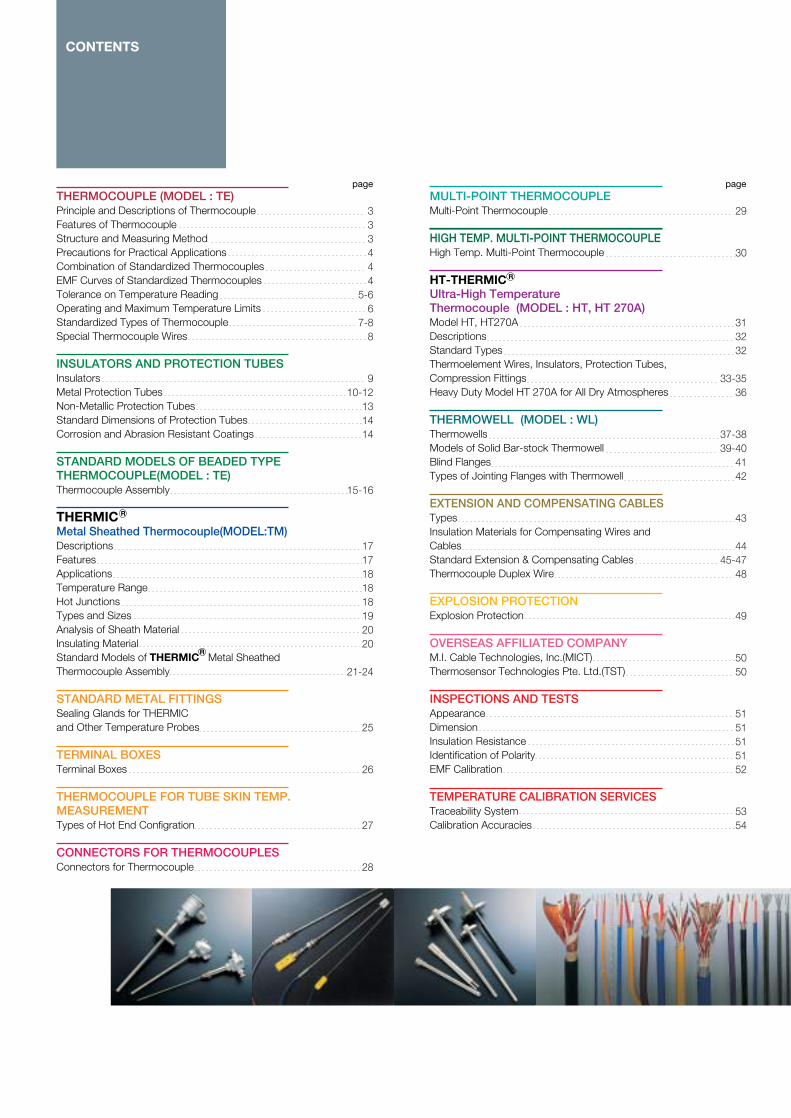
MULTI-POINT THERMOCOUPLEMulti-Point Thermocouple
HIGH TEMP. MULTI-POINT THERMOCOUPLEHigh Temp. Multi-Point Thermocouple HT-THERMIC Ultra-High Temperature Thermocouple (MODEL : HT, HT 270A)Model HT, HT270ADescriptionsStandard TypesThermoelement Wires, Insulators, Protection Tubes, Compression Fittings Heavy Duty Model HT 270A for All Dry Atmospheres
THERMOWELL (MODEL : WL)Thermowells Models of Solid Bar-stock Thermowell Blind FlangesTypes of Jointing Flanges with Thermowell EXTENSION AND COMPENSATING CABLES TypesInsulation Materials for Compensating Wires and Cables Standard Extension & Compensating Cables Thermocouple Duplex Wire
EXPLOSION PROTECTION Explosion Protection
OVERSEAS AFFILIATED COMPANYM.I. Cable Technologies, Inc.(MICT)Thermosensor Technologies Pte. Ltd.(TST)
INSPECTIONS AND TESTSAppearance Dimension Insulation Resistance Identification of Polarity EMF Calibration
TEMPERATURE CALIBRATION SERVICESTraceability System Calibration Accuracies
page page
R
R
333444
5-66
7-88
910-12
131414
15-16
1717181818192020
21-24
25
26
27
28
29
30
313232
33-3536
37-3839-40
4142
43
4445-47
48
49
5050
5151515152
5354
R

THERMOCOUPLE(MODEL : TE)
When two dissimilar metal or alloy conductors are connected together to form a closed circuit and the two junctions are kept at different temperatures, thermal electromotive force (EMF) is generated at the temperature gradient zone along the conductors length in the circuit.Thus, when one end (cold or reference junction) is kept constant at a certain temperature, normally 0℃, and the other end (measuring junction) is exposed to unknown temperature, the temperature at the latter end can be determined by measuring EMF so generated. Such a combination of two dissimilar metal conductors is called "Thermocouple." As described, thermocouple is a "temperature difference sensor" to generate millivolt signal (EMF) only at the temperature gradient segment, which inevitably makes the thermocouple conductor heat treated
in accordance with the temperature profile along the insertion depth. It is not correct, therefore, to use such a thermocouple as once heat treated and so stabilized, for measurement of the other location that has different temperature gradient. Particularly, when measurement is made in shorter insertion depth than previous measurement, it will result in large reading error, since already heat treated segment is exposed to non-temperature gradient zone thus exhibiting spurious EMF, therefore, avoid re-using one thermocouple for measurements at the different locations.
Generally, service life of the thermocouple can not be predicted nor be guaranteed, as the environments of temperature measurement are so various involving handling, installation, corrosion, vibration, thermal cycles and steep change in temperatures.
Industrial thermocouple, in comparison with other thermometers, has the following features:1. Quick response and stable temperature measurement by direct contact with the measuring object.2. If the selection of a quality thermocouple is properly made, wide range of temperature from −270 to 2,300℃ can be measured.3. Temperature of specific spot or small space can be measured.4. Since temperature is detected by
means of EMF generated, measurement, adjustment, amplification, control, conversion and other data processing are easy.5. Less expensive and better interchangeability in comparison with other temperature sensors.6. The most versatile and safe for measuring environments, if a suitable protection tube is employed.7. Rugged construction and easy installation.
Generally, industrial thermocouple is insulated with ceramic beads to prevent thermocouple conductors from short circuit and then inserted into a protection tube to avoid contacting directly to the measuring object or being exposed to the surrounding atmosphere. Our THERMIC
Mineral Insulated Metal Sheathed Thermocouple has a pre-assembled construction composed of thermocouple wires, compacted ceramic powder insulation and protection sheath in one pliable, gas tight cable form. Reference junction should be kept or compensated
at a constant temperature (ideally at 0℃) for measurement. The EMF generated can be measured with a simple moving coil type, electronic type, potentiometric and other indicators or converted to various data processing signals for computer control.
PRINCIPLE AND DESCRIPTIONS OF THERMOCOUPLE
Features of Thermocouple
Structure and Measuring Method
W/Re5-26%
TEMP.INDICATOR
Cold Junction (Reference Junction)
Hot Junction (Measuring Junction)

There are various types of thermocouple, so it is most important to carefully select an appropriate thermocouple for the specific application. In addition, care should be exercised when selecting protection tube, structure of the assembly and installation method in consideration of resistance to heat, pressure, thermal shock, corrosion and vibration. For the best of temperature measurement with thermocouple, overall measuring loop and
components should be carefully designed. Although the importance of reference or cold junction is overlooked and often substituted by a simple electric resistor compensation inside the measuring instrument, stability of the reference junction actually controls measurement accuracy. It is therefore recommended that precision reference devices like our "Zeref V" (18 channels max., 0±0.01℃ Accuracy) or industrial
rack mount model "TRU 100"(100 channels, 0±0.03℃ Accuracy per 15℃ Ambient Span) should be used and Class 1 extension cables should be used for wiring rather than compensating cables. For guidance, various technical brochures, such as,“Instruction Manual for Thermocouple”and“Thermowell and Protection Tube Selection Guide” are available upon request.
Combination of Standardized Thermocouples
EMF Curves ofStandardized Thermocouples
Ref : JIS C 1602-1995 IEC-Pub 584-2 ASTM E988-1996
Note : *W5 is not standardlized yet by IEC,JIS,etc.
Type
W5*
B
R
S
N
K
E
J
T
Alloy Composition of the conductors
Positive (+) Leg
95%Tungsten・5%Rhenium
BP(70%Platinum・30%Rhodium
RP(87%Platinum・13%Rhodium)
SP(90%Platinum・10%Rhodium)
NP (84%Ni・14.2%Cr・1.45%Si)
KP (90%Ni・10%Cr)
EP (90%Ni・10%Cr)
JP (99.5% Iron)
TP (100% Copper)
Negative (-) Leg
74%Tungsten・26%Rhenium
BN(94%Platinum・6%Rhodium)
RN(100%Platinum)
SN(100%Platinum)
NN (95%Ni・4.4%Si・0.15%Mg)
KN (95%Ni・2%Mn・2%Al)
EN Constantan (55%Cu・45%Ni)
JN Constantan (55%Cu・45%Ni)
TN Constantan (55%Cu・45%Ni)
THERMOCOUPLE
Precautions for Practical Applications
−2
−4
−6
−8
−10
−200 −100500 1,000 1,500 2,000 2,500 3,000
0
10
20
30
40
50
K
E J K
N
RS
B
W/Re5-26W/Re5-26%W/Re5-26%
T
E
EMF(mV)IEC-Pub 584-1
Temperature(℃)

Type
B
R
S
N
K
E
J
T
Temp. Range
Tolerance
Temp. Range
Tolerance
Previous Class
Temp. Range
Tolerance
Temp. Range
Tolerance
Previous Class
Temp. Range
Tolerance
Temp. Range
Tolerance
Temp. Range
Tolerance
Temp. Range
Tolerance
Previous Class
Temp. Range
Tolerance
Temp. Range
Tolerance
Previous Class
Temp. Range
Tolerance
Temp. Range
Tolerance
Previous Class
Temp. Range
Tolerance
Temp. Range
Tolerance
Previous Class
Class 1
-
-
-
-
-
*Above 1100℃ Below 1600℃
±[1+0.003(t-1100)]
Above 0℃ Below 1100℃
±1℃
-
Above -40℃ Below 375℃
±1.5℃
Above 375℃ Below 1000℃
±0.004・|t|
Above -40℃ Below 375℃
±1.5℃
Above 375℃ Below 1000℃
±0.004・|t|
Class 0.4
Above -40℃ Below 375℃
±1.5℃
Above 375℃ Below 800℃
±0.004・|t|
Class 0.4
Above -40℃ Below 375℃
±1.5℃
Above 375℃ Below 750℃
±0.004・|t|
Class 0.4
Above -40℃ Below 125℃
±0.5℃
Above 125℃ Below 350℃
±0.004・|t|
Class 0.4
Class 2
-
-
Above 600℃ Below 1700℃
±0.0025・|t|
-
Above 0℃ Below 600℃
±1.5℃
Above 600℃ Below 1600℃
±0.0025・|t|
Class 0.25
Above -40℃ Below 333℃
±2.5℃
Above 333℃ Below 1200℃
±0.0075・|t|
Above -40℃ Below 333℃
±2.5℃
Above 333℃ Below 1200℃
±0.0075・|t|
Class 0.75
Above -40℃ Below 333℃
±2.5℃
Above 333℃ Below 900℃
±0.0075・|t|
Class 0.75
Above -40℃ Below 333℃
±2.5℃
Above 333℃ Below 750℃
±0.0075・|t|
Class 0.75
Above -40℃ Below 133℃
±1℃
Above 133℃ Below 350℃
±0.0075・|t|
Class 0.75
Class 3
Above 600℃ Below 800℃
±4℃
Above 800℃ Below 1700℃
±0.005・|t|
Class 0.5
-
-
-
-
-
Above -167℃ Below 40℃
±2.5℃
Above -200℃ Below -167℃
±0.015・|t|
Above -167℃ Below 40℃
±2.5℃
Above -200℃ Below -167℃
±0.015・|t|
Class 1.5
Above -167℃ Below 40℃
±2.5℃
Above -200℃ Below -167℃
±0.015・|t|
Class 1.5
-
-
-
-
-
Above -67℃ Below 40℃
±1℃
Above -200℃ Below -67℃
±0.015・|t|
Class 1.5
Note :1. Tolerance denotes the maximum allowable value obtained by subtracting the temperature reading or the temperature at the hot junction from the standard temperature converted from the applicable temperature EMF table.
2. Tolerance Class 1 for Types R and S only apply to the Standard or Reference thermocouple.3. |t| denotes the value of temperature (℃) irrespective of positive (+) or negative (-) sign.
4. Tolerances listed in this page apply to the new thermocouple wires.
Tolerances on Temperature Reading1. JIS C1602-1995 IEC 584-2-1982 (Amendment 1-1989) BS/EN 60584-2-1993 DIN/IEC 584-2-1992
Classification of Tolerances
THERMOCOUPLE(MODEL : TE)
*not standardized yet by JIS

Operating and Maximum Temperature Limits to Conductor Diameter (mm)
TYPE
W5
B
R・S
N
K
E
J
T
Temp. Range
Above 426℃ Below 2315℃
Above 870℃ Below 1700℃
Above 0℃ Below 1480℃
Above 0℃ Below 1260℃
Above -200℃ Below 0℃
Above 0℃ Below 1260℃
Above -200℃ Below 0℃
Above 0℃ Below 870℃
Above 0℃ Below 760℃
Above -200℃ Below 0℃
Above 0℃ Below 370℃
Tolerance Grades
Standard
±1%
±0.5%
±1.5℃ or ±0.25%
±2.2℃ or ±0.75%
±2.2℃ or ±2%
±2.2℃ or ±0.75%
±1.7℃ or ±1%
±1.7℃ or ±0.5%
±2.2℃ or ±0.75%
±1.0℃ or ±1.5%
±1.0℃ or ±0.75%
Special
-
±0.25%
±0.6℃ or ±0.1%
±1.1℃ or ±0.4%
-
±1.1℃ or ±0.4%
-
±1.0℃ or ±0.4%
±1.1℃ or ±0.4%
-
±0.5℃ or ±0.4%
Note :The above colour codes are in accordance with ASTM E 230-1998.
Note :(1) Operating temperature limit means the upper temperature where thermocouple can be used continuously in air.(2) Maximum limit means the upper temperature where thermocouple can be used temporarily for short period of time owing to unavoidable circumstances. This graph is given as a guide only, and not to be guaranteed.
2. Tolerance on Temperature Reading to ASTM E230-1998, E988-1996
Wire O.D. (mm)
This table is made in reference to JIS C 1602-1995 and ASTM E988-1996
THERMOCOUPLE
Normal Operating Temp. Range (℃)
1,8001,9001,5001,400
850950
1,0501,1001,200
650750850900
1,000450500550600700400450500550600200200250300
Wire Dia.(mm)TYPE
W5
BR・S
N
K
E
J
T
0.250.500.500.500.651.001.602.303.200.651.001.602.303.200.651.001.602.303.200.651.001.602.303.200.320.651.001.60
Max. Temp. Limit (℃)
2,3002,3001,7001,600
9001,0001,1001,1501,250
850950
1,0501,1001,200
500550600750800500550650750750250250300350
CodeSDT
No.of ConductorsSingle pair, 2 conductorsDual pair, 4 conductorsTriple pair, 6 conductors
0.320.65
1.00
1.60
0.65
0.651.00
1.602.30
3.20
0.651.00
1.602.30
3.20
0.651.00
1.602.30
3.20
0.50
0.50
0.250.50
1.001.60
2.303.20
T
J
E
K
N
B
W5
R・S
200 400 600 800 1000 1200 1400 1600 1800 2000Temp(℃)
Normal Operating Temp. Range
Max. Temp. Limit

Standardized Types of Thermocouple
Type K thermocouple was originally developed by Mr. A. L. Marsh of Hoskins Co., U.S.A. in 1906 and, since then, has undergone many improvements. It has linear EMF characteristics and most widely used as industrial thermocouple with high reliability because of its versatile characteristics. It can be used in oxidizing or inert atmospheres at temperatures up
to 1250℃.Type K thermocouple may be used in hydrogen or cracked ammonia atmospheres if the dewpoint is below-42℃. However, it should not be used in reducing, alternatively oxidizing and reducing, sulfurous or "green-rot" corrosive atmospheres unless properly protected.
"Green-rot" can be minimized by increasing oxygen supply through the use of large diameter protection tube or ventilated protection tube. It can also be minimized by inserting a "getter" to absorb the oxygen in a sealed protection tube. For such a special application, consult our factory.
Type B thermocouple has higher melting point and mechanical strength than other Pt/Rh thermocouples because of its higher content of Rhodium in both legs.Type B thermocouple can be used continuously in oxidizing and neutral atmospheres up to 1600℃ and intermittently up to 1700℃. Even in reducing atmosphere, Type B may be
used for fairly longer period than other Pt/Rh thermocouples, but not generally recommended.Type B thermocouple is recommended especially for the applications requiring precision measurement and durability at high temperatures. This thermocouple has very small EMF up to 100℃, thus for less critical applications, copper leads can
be used as a compensating wire. Precious metal thermocouples are generally sensitive to contaminants and easily be corroded at elevated temperatures. It is essential to keep the thermocouple wire clean and use dust-free high purity (>99.5%) Alumina insulators and protection tubes.
Type R thermocouple has superior mechanical properties to Type S and is recommended for continuous use in oxidizing and inert atmospheres around temperatures up to 1400℃ and intermittently up to 1600℃. However, it should not be used in vacuum, reducing
or metallic vapour atmospheres unless properly protected with clean high purity (>99.5%) Alumina insulators and protection tubes. Among precious metal thermocouples, Type R is most widely used.
Type S thermocouple is the first historic thermocouple originally developed by Le Chatelier in 1886. It had been widely used as a standard thermometer as an interpolation means to determine the temperature scale between the fixed (freezing) points ranging from 630.74℃ of
Antimony to 1064.43℃ of Gold as defined by the International Practical Temperature Scale (IPTS). Applications are similar to Type R, but it has less mechanical strength.
This new thermocouple combination of 84Ni-14.2Cr-1.4Si vs. 95.5Ni.-4.4Si-0.1Mg was first developed by Materials Research Laboratory of the Australian Department of Defense. Further research and evaluation have been extensively carried out by NIST (former NBS), ASTM and other research organizations to
standardize and establish the present EMF table. Type N thermocouple exhibits superior long-term stability and oxidation resistance over type K when used at high temperatures ranging from 600 to 1250℃. By virtue of fine adjustment of chromium content with additions of Si and Mg, it has less EMF shift in the region of "short
range ordering" and also resistant to "Green Rot" corrosion. In comparison with type K, rate of EMF drift is reported to be half or one third over the range of 1000℃ and therefore recommended for use in oxidizing atmosphere of 1000-1200℃ continuous.
THERMOCOUPLE(MODEL : TE)
W5
B Type B (Pt・30%Rh/Pt・6%Rh)Thermocouple 600℃〜1700℃
R Type R (Pt・13%Rh/Pt) Thermocouple 0℃〜1600℃
S Type S (Pt・10%Rh/Pt)Thermocouple 0℃〜1600℃
N Type N (Nicrosil/Nisil) Thermocouple -200℃〜1250℃
K Type K (Ni・Cr/Ni・Al) Thermocouple -200℃〜1250℃
E
J
T

Although this thermocouple combination is not standardized yet by IEC, JIS, etc.,there is a long proven temperature-EMF table that has been adopted by ASTM E988 in 1990. Tungsten 5% Rhenium-Tungsten 26% Rhenium Type is the best improved alloy combination having higher recrystalization temperature of Tungsten above 1,650℃ which is the
only refractory type thermocouple material for regular use at very high temperatures of 1800℃ and intermittently up to 2300℃. At this temperature range, any of platinum-Rhodium group thermocouples will rapidly deteriorate and melt down. This thermocouple, however, has a drawback of severe oxidation when exposed to air or other oxygen containing
atmosphere at above 400℃. Recommended for high temperature measurements under dry Hydrogen, inert gases and vacuum. Unless properly protected like YAMARI's Model HT-270A, use in oxidizing atmosphere should be avoided.
Type E thermocouple has the highest EMF characteristics among industrial thermocouples which allows the best resolution to temperature change. Since it was adopted by ANSI in 1964 and JIS in 1974, type E thermocouple has met
rapidly increasing demands and has been widely used even in large scale thermal and nuclear power stations. It can be used up to 750℃ continuously.For practical use, precautions similar to those for type K are required. Careful
attention is also needed in selection of the indicator to be connected because type E thermocouple has the highest resistivity among the base metal thermocouples.
Type J thermocouple has the second highest EMF characteristics and is recommended for use in reducing, inert, oxidizing or vacuum atmospheres up to 750℃. Because of comparatively less
expensive price, type J has been easily accepted for use in various applications. However, it should not be used in sulphurous atmospheres above 538℃ due to formation of the sulfides that leads
conductors to embrittlement. The iron element is often rusted under high humidity environment, therefore, type J is less desirable than type T for low temperature measurements.
Type T thermocouple has good resistance
to corrosion in moist atmospheres and is
suitable for sub-zero temperature
measurements. It can be used in vacuum
and in oxidizing, reducing or inert
atmospheres up to 400℃. At higher
temperatures, it is susceptible to rapid
oxidation by water vapour. Because of its
stable and precise EMF characteristics,
type T is widely used in laboratories.
Type T is the first thermocouple for which
tolerance in the sub-zero temperature
range has been established. Due to high
thermal conductivity of the conductors,
care must be exercised to eliminate heat
conduction error that often occur on
short stem length type T thermocouple
unit.
Note : Types E, J and T have the same negative (-) legs composing of Cu-Ni with an alloy name of "Constantan," but the alloying ratio of Cu-Ni is adjusted to their respective matching positive (+) legs.Therefore, the negative legs of constantan have no Interchangeability between types.
Special Thermocouple WiresPlatinel 0~1300℃ Oxidizing, InertPt40Rh/Pt20Rh 0~1800℃ Oxidizing, InertNi18Mo/Ni0.8Co 0~1200℃ Reducing, InertW3Re/W25Re 0-2200℃ Reducing, Inert, VacuumMo5Re/Mo41Re 0-1700℃ Reducing, Inert, VacuumChromel/Au.Fe -273~20℃ All atmospheres
THERMOCOUPLE
Type W5 (W・5%Re/W・26%Re)Thermocouple 0-2300℃W5
B
R
S
N
K
E Type E (Ni・Cr /Constantan) Thermocouple -200℃〜900℃
J Type J (Iron/Constantan) Thermocouple 0℃〜750℃
T Type T (Copper/Constantan)Thermocouple -200℃〜350℃

Type
Aluminous CeramicGrade 2
Aluminous CeramicGrade 1
Recrystallized Alumina 99.7%
Magnesia Ceramic
Model
Round 1 bore
Round 2 bores
Round 3 bores
Round 4 bores
Round 6 bores
Oval 2 bores
Code
SH-1
SH-2
SH-3
SH-5
SH-6
DH-3
DH-4
DH-4A
DH-4B
DH-6
DH-8
TH-4
TH-6
QH-3
QH-8
QH-12
QH-14
HH-6
DE-10
DE-12
Nom.O.D.
1
2
3
5
6
3
4
4
4
6
8
4
6
3
8
12
14
6
10×7.5
12×7.5
Nom.I.D.
0.4
1
2
3
4
0.8
1
0.8
1.2
1.5
2
1
1.5
0.8
2
3
4
1
3
4
Length
100
100
100
100
100
100
100
2000
2000
100
100
100
100
100
100
50
50
100
34
34
T/C Wire
3.2
0.5 0.65
1.0 1.6
2.3
3.2
0.5
0.5 0.65
0.5
0.5 0.65
0.65 1.0
0.65 1.0 1.6
0.5 0.65
0.65 1.0
0.5
0.65 1.0 1.6
1.0 1.6 2.3
2.3 3.2
0.5 0.65
1.0 1.6 2.3
2.3 3.2
Material
PS1
PS1 PS0
PS1
PS1
PS1
PS1 PS0
PS1 PS0
PS0
PS0
PS2
PS2
PS1 PS0
PS1
PS1
PS1
PS2
PS2
PS2
PS1 PS0
PS1
Code
PS2
PS1
PS0
MG
Operating Temp.(℃)
1,400
1,500
1,600
1,800
Maximum Temp.(℃)
1,500
1,600
1,800
2,200
Features
Note : Operating and maximum temperatures vary depending on the atmospheres and mode of temperature changes.
Note : Insulators are available in longer length up to 3,000 mm. Consult factory.
INSULATORSCharacteristics
Dimensions
Thermocouples are widely used for temperature measurements of various gases and liquids. If bare thermoelement wires are exposed directly to detrimental atmospheres and fluid, they are often physically and chemically affected resulting in reducing service life with severe
deterioration and corrosion. Thermocouples are, therefore, usually protected with insulators and protection tubes.In selection of suitable insulators and protection tubes, consideration should be given to the materials especially of heat
resistance, mechanical strength, chemical stability, etc. depending on the respective operating conditions. This is the most important point in thermometric practice.
Silimanite Grade. Less porosity with reasonable heat load softening and good resistance to thermal shock.
Gas tight structure with excellent resistance to corrosion. Highest purity among alumina ceramics. Very low Alkalis.
Mullite Grade. Gas tight structure with less heat load softening. Better than PS2.
Porous structure but excellent resistance to corrosion. Only suitable for Basic environment.
INSULATORS AND PROTECTION TUBES
Unit:mm

Material
SS400
304 S.S.
304L S.S.
321 S.S.
316 S.S.
316L S.S.
310S S.S.
347 S.S.
446 S.S.
253 MA
HCF
Carpenter 20Cb-3
50Co-30Cr
Inconel 600
Inconel 601
Inconel 625
Incoloy 800
Code
400
304
304L
321
316
316L
310S
347
446
253
HCF
C2CB
50
600
601
625
800
OperatingTemp. (℃)
Oxi. 600Red. 800
980
980
980
980
980
1,000
980
980
1,000
1,100
1,000
Oxi. 1,150Red. 1,200
1,050
1,050
1,050
870
Features
PROTECTION TUBES
Good resistance to reducing atmosphere but less resistant to oxidation and acids attacks. Thick walled tubes are used in molten aluminium.
Less carbon content (C=0.03%) than 304 S.S. and better resistance to grain boundary corrosion. Subject to stress and "pit" corrosion.
Higher corrosion resistance than 304 S.S. because of its Ti content to prevent carbon preticipation. Excellent resistance to grain boundary corrosion after welding due to less carbon preticipation.
Contains Mo and has excellent resistance to corrosives, heat, acids and alkalis.Less carbon content than 316 S.S. and has better resistance to grain boundary corrosion. Resistant to "pit" corrosion.High Ni-Cr content and good high temperature strength with resistance to oxidation at high temperatures. High mechanical strength.
Because of its Nb-Ta content, prevents carbon preticipation. Higher corrosion resistance than 304 S.S. and excellent resistance to grain boundary corrosion.
Excellent resistance to oxidizing and reducing flames containing sulphur. Suitable for use in non-ferrous molten metals and other high temperature applications, but less mechanical strength.
Superior oxidation resistance to 310 S.S. at high temperatures due to formation of dense and tight oxide layer by silicon and cerium additions. Can be used under sulphurous atmospheres.
One of the best oxidation and corrosion resistant alloys at high temperatures, particularly durable under carburizing and crude oil burning furnaces. Better resistance to sulphur and vanadium-pentoxide than ordinary Cr-Al-Fe alloys. No embrittlement but less mechanical strength at high temperature.
Improved Carpenter 20 Alloy. Cu is newly added to form solid solution with Ni, and Mo content provides enhanced corrosion resistance to non-oxidizing acids, such as Nitric, Fluoric Acid. Virtually immune to pit corrosion.
Excellent resistance to heat, corrosion and abrasion. One of the best alloy against high temperature sulphur bearing atmospheres.
Excellent resistance to oxidizing and reducing atmospheres at high temperatures. But sulphurous atmospheres should be avoided. Immune to stress and "pit" corrosion.
Superior oxidation resistance at high temperatures to Inconel-600, by virture of strong bonding of metal oxide film.Improved strength and stress rupture properties up to 980℃ by Mo and Cb additions, and immune to chloride stress corrosion cracking.
Excellent to high temperature oxidizing atmospheres and thermal shock. About 10 times longer service life than 304 S.S. against high temperature corrosion.
Widely used as a common protection tube against heat and corrosion but not recommended for use in the presence of sulphur or reducing flame. Subject to stress and "pit" corrosion.
Metal Protection TubesCaution : Due to high thermal conductivity of the metal tubes, minimum insertion length should be more than twenty five times of its overall diameter to eliminate heat conduction error.
PROTECTION TUBES
to Next Page

Note:Operating and maximum temperatures of the above tubes vary depending on the measuring environments.Special protection tubes such as Inconel-X750, Nimonic 75〜80, other alloy tubes, etc. are also available upon request. Stainless steels as listed above table are in conformity with JIS Specifications and equivalent to those of AISI, U.S.A.
Material
Incoloy 825
Kanthal A1
80Ni・20Cr
Kurimax
Hastelloy B
Hastelloy C-276
Hastelloy X
Haynes Alloy 25
Titanium
Monel
Tantalum
Molybdnum
Code
825
KA
NC
KU
HB
HC
HX
HY
TI
MN
TA
Mo
OperatingTemp. (℃)
1,000
1,100
1,100
1,200
Oxi. 500Red. 760
1,000
1,100
Oxi. 810Red. 980Oxi. 250
Red. 1,000Oxi. 500Red. 600Oxi. 300
Red. 2,200
Oxi. 400Red. 2,000
Features
PROTECTION TUBES
An improved version of Incoloy 800. All round superior alloy for high temperature applications, particularly in oil refineries against organic sulfides, hydrogen-sulfide and sulphur combustion products.Good resistance to high temperature oxidation but becomes brittle due to recrystallization. Poor mechanical strength above 850℃.
Excellent resistance to molten chemicals and combustion gases. Also good resistance to corrosion by liquid copper.
Good mechanical strength and corrosion resistance at high temperature oxidizing atmospheres but not recommended for use in sulphurizing atmospheres.
Excellent resistance to heat and corrosion, especially to HCl and H2SO4.
Excellent resistance to high temperature oxidizing and reducing atmospheres and also to Cℓ2 gases.
Excellent resistance to oxidizing and carburizing atmospheres at high temperatures. Better machinability and weldability than other Hastelloy alloys.High resistance to oxidizing and carburizing atmospheres at high temperatures.Superior corrosion resistance in cryogenic temperatures but at high temperatures, easily oxidized and becomes brittle.
Excellent resistance to water vapor and sea water at high pressure and corrosion.Excellent heat-resistant material with high resistance to all acids but apt to severe oxidation and embrittlement in air at high temperatures.Excellent mechanical strength up to 1500℃ for applications under inert, reducing and vacuum atmospheres. Resistant to metal vapours at high temperatures but reacts with carbon or graphite. Should not be used in air or oxygen containing gases.
INSULATORS AND PROTECTION TUBES

Material
STPG370
SS400
304 SS
304L SS
321 SS
316 SS
316L SS
310S SS
347 SS
446 SS
Equiv. *1
SANDVIK P-4
253 MA *4
●HCF
●Carpenter 20Cb-3
●Haynes Alloy 25
Kantal A1
80Ni・20Cr
Inconel 600
Inconel 625
Incoloy 825
Incoloy 800
50Co-30Cr(UMCo-50) *2
●Kurimax *3
●Hastelloy B
●HastelloyC-276
Hastelloy X
●Monel 400
Code
370
400
304
304L
321
316
316L
310S
347
446
253
HCF
C2Cb
HS25
KA
NC
600
625
825
800
50
KU
HB
HC
HX
MN
C
<0.25
-
<0.80
<0.030
<0.08
<0.08
<0.030
<0.08
<0.80
<0.20
-
<0.02
<0.02
0.1
-
-
<0.15
<0.10
<0.05
<0.10
0.05〜0.15
-
<0.05
<0.02
<0.05
<0.3
Si
<0.35
-
<1.00
<1.00
<1.00
<1.00
<1.00
<1.50
<1.00
<1.00
1.7
- Trace -
0.4
<1.0
-
-
<0.50
<0.50
<0.50
<1.00
<1.00
-
1.0
<0.08
<1.00
<0.5
Mn
0.30〜0.90
-
<2.00
<2.00
<2.00
<2.00
<2.00
<2.00
<2.00
<1.50
0.6
-
<1.0
1.5
-
-
<1.00
<0.50
<1.0
<1.50
0.30〜1.00
-
<1.0
<1.0
<1.00
<2.0
S
<0.040
<0.050
<0.030
<0.030
<0.030
<0.030
<0.030
<0.030
<0.030
<0.030
-
-
-
-
-
-
<0.015
<0.015
<0.03
<0.015
<0.020
-
<0.03
<0.03
<0.030
<0.024
Ni
-
-
-
11
-
33
32
-
75〜80
>72.00
Bal
38-46
30.00〜35.00
<3.00
-
Bal
Bal
Bal
>63.0
Cr
-
-
18.00〜20.00
18.00〜20.00
17.00〜19.00
16.00〜18.00
16.00〜18.00
24.00〜26.00
17.00〜19.00
23.00〜27.00
21
20
20
20
22
15〜20
14.00〜17.00
21.5
19.5〜23.5
19.00〜23.00
26.00〜30.00
50〜65
-
14.5〜16.5
20.50〜23.00
-
P
<0.040
<0.050
<0.045
<0.045
<0.045
<0.045
<0.045
<0.045
<0.045
<0.040
-
-
-
-
-
-
<0.030
<0.030
<0.030
<0.030
<0.020
-
0.04
<0.04
<0.040
-
Fe
Bal
Bal
Bal
Bal
Bal
Bal
Bal
Bal
Bal
Bal
Bal
Bal
Bal
1.5
Bal
-
6〜10
<5.0
Bal
Bal
Bal
50〜35
<5.0
6.0
18.5
2.5
OTHERS
-
-
-
-
Ti:5×C%
Mo:2.00〜3.00
Mo:2.00〜3.00
-
Nb:10×C%
<N:0.25
Ce 0.04 N 0.17
Al 3.0 Trace Zr+Ti
Mo 2.2Cb+Ta 8×C
Co Bal W 15
Al 5.8
Trace Ti
Trace Co <Cu:0.50
Mo9 Nb+Ta:3.7
Al:<0.2 Ti:0.6-1.2 Mo:2.5〜3.5
Trace Cu, Trace Co, Al, Ti
Co 50 Trace Mo
W4, Trace Nb, Ti
Mo:28 Co:2.5 V:0.6
Mo:15.0〜17.0 Trace W, Co, V
Mo:8.00〜10.00 W0.6, Co1.5 Trace B
Cu:28.0〜34.0 Trace Co
PROTECTION TUBES
NOMINAL ANALYSIS OF METAL PROTECTION TUBES
●Only available in the form of solid bar stock. *1: SANDVIK P4 is Sandvik AB's Trade Mark. *2: UMCo-50 is Mitsubishi Material Co's Trade Mark. *3: Kurimax is Kurimoto Iron Works Co's Trade Mark.
*4: 253MA is Avesta A.B.'s Trade Mark.*5: Haynes 25 is Haynes International Corp.'s Trade Mark.
*6: Carpenter 20 Cb-3 is Carpenter Technology Corp.'s Trade Mark.
Chemical Composition(%wt)
〜10.50
〜13.00
〜13.00
〜14.00
〜15.00
〜22.00
〜13.00
8.00
9.00
9.00
10.00
12.00
19.00
9.00

OperatingTemp. (℃)
1,000
1,400
1,500
1,600
1,300
1,600
1,650
1,400
1,650
1,500
1,550
1,350
1,250
1,800
Features
Non-Metallic Protection Tubes
99.99%QuartzExcellent to thermal shock but fragile. Poor resistance to alkalis but good to acids. Less gas-tightness in hydrogen and reducing gases. High thermal conductivity.
60%Alumina-40%SilicaSintered alumina. Better than PT2 but slightly less thermal shock resistance.Recommended for use in heating furnace and regenerator, impervious.
High alumina ceramic. Good resistance to thermal shock. Recommended for use in coal or oil burning and electric furnaces. Slightly porous.
99.5%AluminaSuperior chemical stability and better than PT1. Recommended for use in molten steel, slag and molten glass, impervious.77%Alumina-23%ChromeExcellent resistance to heat and abrasion.Recommended for temperature measurements of molten copper and other nonferrous metals.60%Mo-40%ZrO2
High heat conductivity, good thermal shock resistance and corrosion resistance in molten metals. Recommended for continuous use in molten steel but not suitable for use in oxidizing atmosphere at high temperatures.Pure fine grain Alpha SiC, 99.9% Highest Grade among SiC material. Gas Tight. Low friction, high hardness. Five times as higher thermal conductivity of Alumina. Suitable for all the dry atmospheres but attacked by water vapour.99% SiCPorous but good resistance to acids and alkalis.Recommended for use in air neutral atmospheres up to 1,400℃ and also in high temperature stagnant furnace atmosphere as an outer protection tube, etc. Attacked by water vapour.
INSULATORS AND PROTECTION TUBES
Caution : 1. Operating and maximum temperatures vary depending on the heat pattern and atmosphere. For low thermal conductivity ceramic tubes, preheating and slow insertion into the furnace are
recommended. Generally, insertion speed of 100 to 150 mm per minute after preheating around 80〜100℃ will be adequate.2. Minimum insertion length of the non-
metallic tube should be more than fifteen times of its overall diameter, excepting those of higher heat conductivity materials like SiC and Cermet which need twenty five times or more.
Material
TranslucentQuartz
TransparentQuartz
Silimanite
Mullite
Recrystallized Alumina
Cermet(Chrome-Alumina)
Cermet(Cermotherm)
Static Press Sintered Alpha-SiC
Recrystallized SiliconCarbide
Self-bonded Silicon Carbide
Clay-bonded Silicon Carbide
Nitride Bonded Silicon Carbide
Silicon Nitride (Si3N4)
Sialon
Zirconia
Code
QT
PT2
PT1
PT0
LT1
2040
Y0
Y1(GK)
Y2(KT)
Y3(NF)
Y4(RF)
SNT
SLN
ZR 1706
99% SiCVery low porosity. Excellent resistance to thermal shock, corrosion and abrasion at high temperatures. Recommended for use in oxidizing and reducing atmospheres up to 1,650℃. but attacked by water vapour.89%SiC+8.5%SiO2+0.7%Al2O3+0.7%Fe2O3
Good heat conductivity. Better resistance to thermal shock than oxide ceramic tubes. Like Other SiC types, use under water vapour must be avoided.78%SiC+3%SiO2+18%Si3N4(Si2ON2)Excellent performance superior to Y3 SiC but contains Si3N4. Most suitable for use in molten aluminum, reheating. Attacked by water vapour.Excellent thermal shock resistance. Less corrosion to acids and alkalis. High hardness. Fairly good resistance against most of molten metals.Good oxidation and thermal shock resistance. Better corrosion resistance to molten metals, especially good for molten Aluminum bath than Silicon-Nitride. Durable to iron and steel up to 1,600℃.MgO Stabilized ZrO2
Gas-tight and exceptionally good thermal shock resistance. Chemically stable against molten metals other than alkalis. Recommended for use in molten special metals, slag and glass up to 1,800℃. Suitable for use in high temp. protection tube up to 1,900℃ where PT0 Alumina softens.
PT0 PT1 PT2 QT 2040 LT1 SNT Y1 Y2 Y3 Y4

Standard Dimensions of Protection Tubes
PROTECTION TUBES
Metallic Tubes Non-Metallic Tubes
Material
304 S.S.
304L S.S. *1
321 S.S. *1
316 S.S.
316L S.S.
310S S.S.
347 S.S. *1
446 S.S.
50Co30Cr
80Ni20Cr
INCONEL
600
Treatment
Glass Lining
Teflon *1
HARD SURFACING.Flame Spray,Plasma Spray
Thickness(mm)
1〜1.2
0.3
0.3〜0.6
CompositionBorosilicate glass over plain steel
FEPover metalsColmonoy *2
Fukudalloy *3
Stellite W.C. *4
Maximum Temp. (℃)
450
120
1,000
Nominal O.D.
10.0
12.0
13.8 *2
15.0
17.3 *2
21.7 *2
27.2 *2
21.3
26.9
22.0
27.0
10.0
13.0
15.0
22.0
26.7
Nominal I.D.
8.0
9.0
9.4
11.0
12.7
16.1
21.4
16.0
21.6
16.0
21.0
8.0
11.0
11.0
16.0
21.0
Length
4,000
4,000
5,500
4,000
5,500
5,500
5,500
4,000
4,000
4,000
4,000
4,000
4,000
4,000
4,000
4,000
Unit : mm
Corrosion and Abrasion Resistant Coatings
Material
PT1
PT2
PT0
QT
Y1
Y2
Y3
Y4
Nominal O.D.
6.0
8.0
10.0
13.0
15.0
17.0
21.0
25.0
6.0
8.0
10.0
13.0
15.0
17.0
21.0
25.0
8.0
15.0
18.0
25.0
30.0
35.0
25.0
40.0
40.0
Nominal I.D.
4.0
5.0
6.0
9.0
11.0
13.0
16.0
20.0
4.0
5.0
6.0
9.0
11.0
13.0
16.0
20.0
6.0
13.0
15.0
17.0
15.0
25.0
12.0
20.0
20.0
Length
Unit : mm
FeaturesSuitable for protection against oxidation and gas penetration. Poor thermal shock resistance.Suitable for concentrated hydrochloric, sulphuric and nitric acids depending on temperatures.
Suitable for protection from corrosion and abrasion of mother metals or alloys surface.
For other special coating requirements, consult our factory.
*1,2,3,4 Trade Marks of Dupont, Colmonoy, Fukuda Alloy, and Cabot respectively.
150
300
300
500
500
500
500
500
300
300
300
500
500
500
500
500
100
100
100
1,000
1,000
1,000
150
1,000
400
〜
〜
〜
〜
〜
〜
〜
〜
〜
〜
〜
〜
〜
〜
〜
〜
〜
〜
〜
〜
〜
〜
〜
〜
1,000
3,000
3,000
3,000
2,000
2,000
2,000
2,000
1,400
3,000
3,000
3,000
2,000
2,000
2,000
2,000
1,000
2,000
2,000
1,400
1,700
1,800
900
1,000
Note:*1 Only scheduled tubes are available.*2 Dimensions for scheduled tubes.
(Alumina coating is also available.)

Standard Models of Beaded Type Thermocouple Assembly (Model : TE)
STANDARD MODELS OF BEADED TYPE THERMOCOUPLE(MODEL : TE)
For economy and quicker delivery, 16 popular models were selected in five STANDARD LENGTH of 500, 800, 1000, 1200, 1500 mm through numerous proof
in design and installations. It is recommended that the customer specify the probe length longer than actually needed among the above standard
length, so that error by heat conductivity is eliminated and the insertion depth can be adjusted as required.
TE01 K S L S32- - -
Model No. Type No. of Con-ductors
Dia. TotalLength
TerminalBlock
1Basic Type with Bead Insulators
TE01
2Metalic Protection TubeType with Slide Flange
TE12 TE12 K S L KN 2232- - - - /
@
Model No. Type No. of Con-ductors
Dia. TotalLength
TerminalBox
Pro.TubeDie.
304
Material
/JIS10K25AFF 304
MaterialFlange Rating
3Screwed-in Metalic Protection Tube Typewith Hex. Nipple
TE13 -KN
TerminalBox
15
Pro.TubeDie.
TE13 K S L32- - / -
/ -
Model No. Type No. of Con-ductors
Dia. TotalLength
InsertionLength
304
Material
/R1/2 304
MaterialThread
4Metalic Protection Tube Typewith Fixed Flange
TE14/JIS10K25AFF 304
MaterialFlange Rating
-KN
TerminalBox
22
Pro.TubeDie.
TE14 K S L32- - / -
/ -
Model No. Type No. of Con-ductors
Dia. TotalLength
InsertionLength
304
Material
5Ceramic Protection Tube Type with Metal Support and Slide Flange
TE2222
SupprtDia.
/JIS10K25AFF304
Material
304
MaterialFlange Rating
-KN
TerminalBox
15
Pro.TubeDie.
TE22 R S L05- - / -
/ @-
Model No. Type No. of Con-ductors
Dia. TotalLength
InsertionLength
PT0
Material
/
6Screwed-in Ceramic Protection Tube Typewith Hex. Nipple
TE23 -KN
TerminalBox
13
Pro.TubeDie.
TE23 R S L05- - / -
/ -
Model No. Type No. of Con-ductors
Dia. TotalLength
InsertionLength
PT0
Material
R3/4
Thread
304
Material
/
7Ceramic Protection Tube Type with Fixed Flange
TE24JIS10K25AFF
Flange Rating
304
Material
-KN
TerminalBox
13
Pro.TubeDie.
TE24 R S L05- - /
/
-
/ -
Model No. Type No. of Con-ductors
Dia. TotalLength
InsertionLength
PT0
Material
8Ceramic Protection Tube Type with FixedFlange on Metal Support
TE25 -A
SupportLengyh"A"
-KN
TerminalBox
13
Pro.TubeDie.
TE25 R S L05- - / /
/ -
Model No. Type No. of Con-ductors
Dia. TotalLength
InsertionLength
PT0
Material
JIS10K25AFF
Flange Rating
304
Material
/
L
L
L
U
U
U
U
U
U
WELDED
L
WELDED
L
A
L
WELDED
22
SupportDia.
304
Material
-/
L
L
U
U
U
U
U
U

STANDARD MODELS OFBEADED TYPE THERMOCOUPLE
9Dual Protection Tube Type Inner Ceramic and Outer MetalTubes with Slide Flange
TE32 13
InnerTubeDia.
JIS10K25AFF
Flange Rating
304
Material
KN
TerminalBox
TE32 R S L05- - -
/
- /
-
Model No. Type No. of Con-ductors
Dia. TotalLength
PT0
Material
22
OuterTube
/ @304
Material
10Screwed-in Dual Protection Tube Type Inner Ceramic andOuter Metal Tubes with Hex. Nipple
TE3313
Inner TubeDia.
304
Material
KN
TerminalBox
TE33 R S L05- - / -
/ -
Model No. Type No. of Con-ductors
Dia. TotalLength
-
InsertionLength
PT0
Material
22
OuterTube
/ -304
Material
R1
Thread
/
11Dual Protection Tube Type Inner Ceramic and Outer Metal Tubes with Fixed Flange
TE34 13
InnerTubeDia.
KN
TerminalBox
TE34 R S L05- - / -
/ -
Model No. Type No. of Con-ductors
Dia. TotalLength
-
InsertionLength
PT0
Material
22
OuterTube
/ JIS10K25AFF
Flange Rating
304
Material
/-304
Material
12Dual Ceramic Protection Tube Type with Slide Flange Optional Metal Support
TE42 8
InnerTubeDia.
KN
TerminalBox
TE42 R S L05- - / - / -
Model No. Type No. of Con-ductors
Dia. TotalLength
-
InsertionLength
PT0
Material
13
OuterTube
/ 22
Support Dia.
PT1
Material
304
Material
/-
13Screwed-in Dual Ceramic Protection Tube Typewith Hex. Metal Support
TE43 -
8
Inner TubeDia.
KN
TerminalBox
TE43 R S L05- - / -
/ -
Model No. Type No. of Con-ductors
Dia. TotalLength
-
InsertionLength
PT0
Material
13
OuterTube
/ 304
Material
/PT1
Material
- R1
Thread
14Dual Ceramic Protection Tube Type with Fixed Flange Metal Support
TE44JIS10K25AFF
Flange Rating
304
Material
/
8
InnerTubeDia.
KN
TerminalBox
TE44 R S L05- - / -
/ -
Model No. Type No. of Con-ductors
Dia. TotalLength
-
InsertionLength
PT0
Material
13
OuterTube
/ PT1
Material
-
16L-bent Type
TE62
15Dual Ceramic Protection Tube Type with Fixed Flange on Metal Support
TE45 ASupportLength"A"
JIS10K25AFF 304Material
/
13InnerTubeDia.
KNTerminalBox
TE45 R S L05- - / -- /
-
Model No. Type No. of Con-ductors
Dia. TotalLength
/InsertionLength
PT0Material
21OuterTube Die.
/ PT0Material
- -
304Material
304Material
22Pro.Tube"A" Dia.
KNTerminalBox
TE62 K D L32- - / -
-/
Model No. Type No. of Con-ductors
Dia. TotalLength
/InsertionLength
22Pro.Tube"B" Dia.
/
L
L
U
U
U
U
U
U
U
WELDED
L
WELDED
L
L
WELDED
L
L
A
WELDED
L
AB
27
SupportDia.
/ 304
Material Flange Rating
U
U
U
U
U
U
U
JIS10K25AFF
Flange Rating
304
Material
/@

THERMIC(MODEL : TM)
THERMIC is a trade name of YAMARI’s metal sheathed thermocouple that is covered by a heat and corrosion resistant alloy sheath in which high purity MgO powder is tightly compacted around the thermocouple conductors. THERMIC metal sheathed thermocouple has high electrical insulation resistance and
excellent compressive strength owing to its compact integral construction. It has also high reliability and accuracy because its EMF tolerance always guaranteed to fall within the limits of error stipulated by IEC, JIS (C 1605-1995), ASTM, BS, DIN, etc.
Descriptions
R METAL SHEATHED THERMOCOUPLE
THERMIC R
1) Small Size and Quick Response : By virtue of its integrated structure comprising of thermoelement wires, insulating powder material and a protection sheath compacted and drawn together into a small size gas-tight tubular cable form, THERMIC has very quick response to temperature changes, without disturbing temperature of the measuring object.
2) High Flexibility and Ease of Installation : THERMIC can be easily installed owing to its high mechanical strength and pliability up to bending radius equal to 2 times of the sheath O.D., and can stand 4 times’ repeated bendings before heating. Once after installed and heated, however, THERMIC should never be twisted or bent to any direction, as the compacted powder insulation is pressure sintered inside the sheath during the measurement, thus changing to solid ceramic which may yield cracks by bending to provide paths for the metal elements to diffuse changing the alloy compositions or allow the thermocouple wires to touch each other.
3) Excellent Resistance to Heat, Corrosion, Vibration and Pressure : Made of high purity MgO powder tightly compacted in a heat and corrosion resistant metal tube, THERMIC is produced by drawing under high pressures in excess of 314MPa (3,200 kgf/cm2 ) therefore, it is highly gas-tight, least corrosion against surrounding atmospheres and withstands severe vibration and high pressures from 137MPa (1,400 kgf/cm2 ) to max. 196MPa (2,000 kgf/cm2 ).
4) Wide Selection of Cable Types : From very fine sheath O.D. of 0.25 mm to 12. 7 mm, and up to 500 meters in one continuous length are available in some O.D. Thermoelement wires of 2-pairs and 3-pairs are also available.
5)Wide Range of Measuring Temperature : Available in types T, J, E, K, N and R with a variety of alloy sheath depending upon measuring environments. Temperature range can be extended from cryogenic of –200℃ to high temperature up to +1,250℃ by selecting an appropriate combination of thermocouple type and sheath material. To the customer’s special requirements, various exotic Metal Sheathed Thermocouples such as Tantalum sheathed Tungsten-Rhenium and Platinum sheathed Type R and B can be supplied.
6) Longer Service Life : Despite much smaller overall diameter and light weight, THERMIC has remarkably longer service life over the conventional large beaded type thermocouple. According to our experiment for long-term EMF drift studies of THERMIC thermocouple, 8 mm O.D. Inconel 600 sheathed Type K samples of only 1.30 mm dia. conductors had a service life of over 20,000 hours (2.3 years), at 1,000℃ in air without noticeable drift from an initial calibration. In contrast, a conventional beaded thermocouple of 3.2 mm O.D. Type K conductors with 21.7 mm O.D. Inconel 600 protection tube failed less than 10,000 hours (approx. 11 months) after deviated from the specified limits of error due to oxidation of Type K conductors. THERMIC offers more than twice as large saving on the temperature measurement costs.
FeaturesTHERMIC R
CUPRO-NICKEL
304SS,321SS,316SS
446S
310SS
NICROBELLHASTELLOY X
INCONEL600INCONEL625

Iron and Steel and Non-Ferrous Industries: blast furnaces, converters, soaking pits, annealing furnaces, electric furnaces, vacuum induction furnaces, continuous casters, heat treatments, strip mills, etc.Electric Power and Gas Processing Industries: superheaters, regenerators, boilers; padded, chordal and various types of skin temperature monitors, water cooling, feeding and draining; turbine casings, thrust metals and bearings; generator gas, natural gas; LPG, LNG, etc.Electric and Electronic Industries: motors, transformers and generators; process temperature controls for semi-conductors, IC, LSI, electron tubes, etc.Glass and Ceramic Industries: rotary kilns, tunnel kilns and other various kilns for glass, cement and brick, flues, preheaters, tempering kilns, etc.Chemical and Petro-chemical Industries: sulphur recovery unit, various reactors for gases, liquids, etc., plastic injectors and molders, cracking and reactor towers, synthetic textiles, pharmaceutical processings, etc.Nuclear Power Stations: reactors, cooling gas and water, fuel rods, etc. H.T.G.R., F.B.R. and various nuclear researchesShipbuilding Industry: skin temperature of LNG and LPG carriers, regenerators, diesel engines, etc. associated long-term monitoring and safety devices, etc.Aircrafts and Aerospace Industries: combustion and exhaust gases of jet and rocket engines, etc. associated monitoring functions of temperature controls, re-entry temperature.Textile & Foodstuff Industries: temperature controls for fiber injectors, plate and roll heaters, dyeing process, sugar refining, meat processing, bakeries, confectioneries, breweries, retort and frozen food processing, etc.Others: experimental and laboratory studies on plasma arc, electron beam, laser, single crystal growth, and other physical, electronic, medical properties, biotechnical researches.
ApplicationsTHERMIC R
Temperature RangeTHERMIC R
Hot JunctionsTHERMIC R
THERMIC R
-200 0 200 400 600 800 1000 1200 1400 1600 1800
T
J
E
K
N
R
-200 0 200 400 600 800 1000 1200 1400 1600 1800
Thermoelement Wires Sheath MaterialUnit:℃ Unit:℃
CUPRO-NICKEL
304SS,321SS,316SS304SS,321SS,316SS
446S
CUPRO-NICKEL
304SS,321SS,316SS
446S
310SS
NICROBELLHASTELLOY X
INCONEL600INCONEL625
310SS
NICROBELLHASTELLOY X
INCONEL600INCONEL625
■
■
■
■
■
■■
■
■
■
* Due to limitation of heat resistance of the metal sheath, maximum measuring temperatures may be reduced than those quoted on bare thermocouple wires.
Our specifications and procedures of making the above hot junctions conform to ASTM E 235, IEC 1515-1995 and JIS C 1605-1995.
Thermoelement wires are welded together directly at hot end of the sheath to form a hot junction. Not recommended for type T and R due to wide difference in melting points between composed metals and alloying compatibility. To overcome such a difficulty, a patented special junction is made on request.Quick response and suitable at high temperature and pressure but not recommended for use in hostile, vibrating and noise generating field.
Thermoelement wires are welded together to form a hot junction which is completely isolated both mechanically and electrically from the sheath closure.Slower response than Type I but less deterioration of EMF and suitable for a long term service in critical and noise generating field.
Thermoelement wires are welded together to form a bare hot junction by protruding from the sheath.Quickest response and can detect even a slight temperature change instantaneously, but not durable for long time in corrosive, high temperature and high pressure atmospheres. Care must be exercised to prevent from moisture ingress at low temperature or during storage.
Type (Grounded)
Type (Ungrounded)
Type (Exposed)

THERMIC(MODEL : TM)
Conductor twisted type THERMIC eliminates noise interference :For use under noise generating or RF interference field, conductor twisted type THERMIC is available in calibrations of K, J, E, T and N with stainless steel and Inconel sheath of 1.6 mm to 3.2 mm nominal O.D. This special thermocouple is eminently suited to effectively eliminate normal mode noise. Maximum cable length is 500 meters. This special THERMIC can be handled in the same way as ordinary THERMIC thermocouples, and effectively reduces disturbance on EMF output.
Types and Sizes
R METAL SHEATHED THERMOCOUPLE
THERMIC R
Special sheath material : 304, 304L, 321, 347, 316, Inconel 625, Incoloy 825, Hastelloy X, Cupro-nickel, etc. are available.Optional O.D. Size : 1.5mm, 2.0mm, 3.0mm, 4.5mm, 6.0mm, 9.5mm, 10.5mm, 12.7mm, 15.9mm, and 19.1mm can be supplied.
Standard Sheath MaterialNom.O.D. (mm)
Wire Dia.(mm)
Wall Thick. (mm)
Type Max.Length (m)
Weight (g/m)
Inconel 600316LSSInconel 600316LSSInconel 600, 310SS316LSSInconel 600, 310SS316LSSInconel 600, 310SS316LSSInconel 600, 310SS316LSSInconel 600, 310SS316LSSInconel 600, 310SSHastelloy X 316LSSInconel 600, 310SSHastelloy X316LSSInconel 600, 310SS316LSSInconel 600, 310SS316LSSInconel 600, 310SS316LSSInconel 600, 310SS316LSSInconel 600, 310SS316LSSInconel 600, 310SS316LSSInconel 600, 310SS316LSSInconel 600, 310SS316LSSInconel 600, 310SS
K
K・E・J
K・E・J・T
N・K・E・J・T・R
N・K・E・J・T
N・K・E・J・T・N・R
N・K・E・J・T・N・R
N・K・E・J・T・N
N・K・E・J・T・N
K・E・J・T
K・E・J・T
K・E・J・T
K・E・J・T
K・E・J・T
K・E・J・T
K・E・J・T
K・E・J・T
K・E・J・T
0.25
0.5
1.0
1.6
2.2
3.2
4.8
6.4
8.0
1.6
3.2
4.8
6.4
8.0
3.2
4.8
6.4
8.0
0.04
0.10
0.18
0.25
0.36
0.53
0.79
1.04
1.30
0.25
0.48
0.74
0.97
1.22
0.30
0.53
0.71
0.89
0.05
0.08
0.13
0.18
0.25
0.36
0.53
0.74
0.91
0.18
0.36
0.53
0.74
0.91
0.38
0.53
0.74
0.91
5
300
480
300
300
500
200
100
80
300
500
200
100
80
150
200
100
80
0.4
1.3
5
13
24
51
115
193
300
13
45
102
222
350
33
80
130
210
Single Pair
Dual Pair
Triple Pair
Sheath
Wire
MgO

THERMIC R
Analysis of Sheath MaterialTHERMIC R
C
<0.08
<0.08
<0.03
<0.08
<0.15
<0.2
<0.15
<0.10
<0.05
-
<0.15
-
Si
<1.0
<1.0
<1.0
<1.00
<1.5
<1.0
<0.50
<0.50
<0.5
-
<1.0
1.4
Mn
<2.0
<2.0
<2.0
<2.00
<2.0
<1.5
<1.0
<0.50
<1.0
<1.5
<1.0
-
P
<0.04
<0.04
<0.04
<0.04
<0.04
<0.04
<0.03
<0.015
<0.03
-
<0.04
-
S
<0.03
<0.03
<0.03
<0.03
<0.03
<0.03
<0.015
<0.015
<0.015
-
<0.03
-
Ni
8-11
9-13
12-16
9-13
19-22
-
>72
Bal
38-46
11
Bal.
81
Cr
18-20
17-19
16-18
17-19
24-26
23-27
14-17
20-23
19.5-23.5
-
20.5-23
14.5
Fe
Bal.
Bal.
Bal.
Bal.
Bal.
Bal.
6-10
<5.0
Bal.
-
18.5
-
Other
-
>Ti 5×C%
Mo 2-3
>Nb10×C%
-
N<0.25
Cu<0.5
Mo 9 Nb+Ta:3.7
Mo 2.5-3.5 Al<0.2 Ti<1.2
Cu Bal. Fe<1.0 Zn<1.0
Mo 18.5 Co 1.5 W 0.6
Nb 1.8 Mg 0.15
Sheath
304SS
321SS
316LSS
347SS
310SS
446SS
Inconel 600
Inconel 625
Incoloy 825
Cupro-nickel
Hastelloy X
Nicrobell B
Unit : %
Insulating MaterialPurity
THERMIC R
Standard
High Purity
MgO
96.3〜97.3
99.47〜 99.72
SiO2
1.45〜2.06
0.042〜 0.14
CaO
0.73〜1.25
0.14〜0.21
Fe2O3
0.16〜0.30
0.034〜 0.104
Al2O3
0.06〜0.30
0.30〜0.08
B
85〜1,000ppm
10〜20ppm
Cd
<10ppm
<10ppm
S
<50ppm
<50ppm
C
<200ppm
<200ppm
Unit : %
GradeComposite
Physical PropertiesInsulatingMaterial
MgO
MeltingPoint(℃)
2,800
ResistivityCoeff. of thermal
expansion (E) ℃-1Thermal Conductivity (℃)
Caℓ・sec-1・cm-2・cm℃-1
℃
980
℃
20〜1,400
Ω・cm
3×107
E×10-7
140
℃
1,200
Porosity
22
C×104
61
Moh’sHardness
6
Densityg・cm-3
3.58

For economy and quicker delivery, 28 popular models are selected in five STANDARD LENGTH of 500, 800, 1000, 1200, 1500 mm through numerous proof
in design and installations. It is recommended that the customer specify the probe length longer than actually needed among the above standard
length, so that error by heat conductivity is eliminated and the insertion depth can be adjusted as required.
THERMIC(MODEL : TM)
R METAL SHEATHED THERMOCOUPLE
Standard Models of THERMICMetal Sheathed Thermocouple Assembly (MODEL : TM)
R
1Basic Type, Projected Conductors
TMATMA K S 5032-
Type No. of Con-ductors
Dia. H.J.
L- -
Length
316LSheath
/
L 50
2Basic Type with Terminal Block
TMA TMAS TMA
TMAS
K S S48-
Model No.
Model No.
Type No. of Con-ductors
Dia. H.J. TerminalBlock
L- -
Length
316LSheath
/
※TMAS…Spring loaded type (Max.stroke of spring 10mm.)L
3Basic Type with Terminal Box
TMAS TMAS K S KN48-
Model No. Type No. of Con-ductors
Dia. H.J. TerminalBox
L- -
Length
316LSheath
/
※Spring loaded type (Max.stroke of spring 10mm.)L
4Flexible Shield Lead Type
TMB TMB K S
VX13
48-Model No. Type No. of
Con-ductors
Dia. H.J.
Lead
L- -
Length
-
LeadLength
316LSheath
/
L A50
70
5Flexible Tube ArmouredLead Type
TMBF TMBF K S
VX13
48-Model No. Type No. of
Con-ductors
Dia. H.J.
Lead
L- -
Length
-
LeadLength
316LSheath
/
L A55
70
6Flexible Lead TypeWith Quick Connector
TMBDL TMBDS TMBDL K S
KX13
48-
-
Model No.
Model No.
Type No. of Con-ductors
Dia. H.J.
Lead
L- -
KX13Lead
-
Length
A1 A2-LeadLength
Lead Length
316LSheath
/
TMBDS
※TMBDS…Miniature connector
7Flexible Lead Typewith Metal Connector
TMBEL TMBES TMBEL K S
KX13
48-
-
Model No.
Model No.
Type No. of Con-ductors
Dia. H.J.
Lead Lead
L- -
KX13-
Length
A1 A2-LeadLength
316LSheath
/
TMBES
※TMBES…Miniature connector
A1 A255L
70
L 55 A1 A2
70
A
A

8Flexible Lead Type with Metal Plug
TMBEL TMBES TMBEL K S
KX13
48-
Model No.
Type No. of Con-ductors
Dia. H.J.
Lead
L- -
Length
-
LeadLength
316LSheath
/
TMBES
※TMBES…Miniature connector
9Flexible Lead Typewith Meatal Plug & Socket
TMBEL TMBES TMBEL K S
KX13
48-
Model No.
Type No. of Con-ductors
Dia. H.J.
Lead
L- -
Length
-
LeadLength
316LSheath
/
FASocket
-
TMBES
※TMBES… Miniature connector
10Flexible Lead Typewith Meatal Plug & Receptacle
TMBEL TMBES TMBEL K S
KX13
48-
Model No.
Type No. of Con-ductors
Dia. H.J.
Lead
L- -
Length
-
LeadLength
316LSheath
/
FCReceptacle
-
TMBES
※TMBES… Miniature connector
L A
70
11Bayonet SpringLoad Type
TMBYL TMBYS TMBYL K S
KX13
48-
Model No.
Type No. of Con-ductors
Dia. H.J.
Lead
L- /
Length
-
-
LeadLength
316LSheath
/ E
TMBYS
※TMBYL…8A nozzle(13.8mm.O.D.)※TMBYS…6A nozzle(10.5mm.O.D.)L A
E
55
70
12Exposed Terminal Type
TMCL TMCS TMCL K S 48-
Model No.
Type No. of Con-ductors
Dia. H.J.
L-
Length
316LSheath
/
TMCS
※TMCL…TL Terminal Box TMCS…TS Terminal Box
L
13Quick Connector Type(Compensated Contact pins)
TMDL TMDSKX13
Lead
TMDL K S 48-
Model No.
Type No. of Con-ductors
Dia. H.J.
L- -
Length
Length
-
316LSheath
/
TMDS
※TMDS… Miniature connector
14Quick Connector Type with Plug(Compensated Contact pins)
TMDL TMDS TMDL K S 48-
Model No.
Type No. of Con-ductors
Dia. H.J.
L-
Length
316LSheath
/
TMDS
※TMDS…Miniature connectorL
L A55
L A55
55L A
THERMIC R
A
A
A
A

THERMIC(MODEL : TM)
R METAL SHEATHED THERMOCOUPLE
15Quick Connector Type with Plug & Socket(Compensated Contact pins)
TMDL TMDS TMDL K S 48-
Model No.
Type No. of Con-ductors
Dia. H.J.
L-
Length
316LSheath
/
TMDS
※TMDS…Miniature connectorL
16Metal Connector Type
TMEL TMES TMEL K S
KX13
48-
Model No.
Type No. of Con-ductors
Dia. H.J.
Lead
L- -
Length
-
LeadLength
316LSheath
/
TMES
※TMES… Miniature connectorL A
70
17Metal Connector Type with Plug
TMEL TMES TMEL K S 48-
Model No.
Type No. of Con-ductors
Dia. H.J.
L-
Length
316LSheath
/
TMES
※TMES…Miniature connectorL
18Metal Connector Typewith Plug & Socket
TMEL TMES
※TMES…Miniature connector
TMEL K S 48-
Model No.
Type No. of Con-ductors
Dia. H.J.
F-
Socket
316LSheath
/
TMES
L
19Metal Connector Typewith Plug & Receptacle
TMEL TMES TMEL K S 48-
Model No.
Type No. of Con-ductors
Dia. H.J.
L- FC-
Receptacle
316LSheath
/
TMES
※TMEL…TL Terminal Box※TMES…Miniature connector
L
20Terminal Head Type
TMH TMH K S 48-Model No. Type No. of
Con-ductors
Dia. H.J.
L- -
Length
KNTerminalBox
316LSheath
/
L
21Screwed-in Hex. Nipple Type
TMNB TMNBSR1/2
Thread
- -KNTerminalBox
InsertionLength
304Material
/
TMNB K S 48-
Model No.
Type No. of Con-ductors
Dia. H.J.
L-
Length
316LSheath
/ /
TMNBS
※TMNBS… Spring-loaded type (Max.stroke of spring 10mm.)L
U
L-
Length
-
Length
A
U

22Screwed-in Plain Nipple Type(without Bushing)
TMN TMNS TMN K S 48-
Model No.
Type No. of Con-ductors
Dia. H.J.
L- /
/
Length InsertionLength
316LSheath
/
TMNS
※TMNS… Spring loaded type (Max.stroke of spring 10mm.)
R1/2Thread
-
-KNTerminalBox
304MaterialL
U
23Screwed-in Hex. Nipple Typewith Union
TMUNB TMUNBS TMUNB K S 48-
Model No.
Type No. of Con-ductors
Dia. H.J.
L- /
/
Length InsertionLength
316LSheath
/
TMUNBS
※TMUNBS… Spring loaded type(Max. stroke of spring 10mm.)
R1/2Thread
-
-KNTerminalBox
304MaterialL
U
24Screwed-in Plain Nipple Typewith Union
TMUN TMUNS TMUN K S 48-
Model No.
Type No. of Con-ductors
Dia. H.J.
L- /
/
Length InsertionLength
316LSheath
/
TMUNS
※TMUNS… Spring loaded Type(Max. stroke of spring 10mm.)
R1/2Thread
-
-KNTerminalBox
304MaterialL
U
25Flanged Nipple Type
TMNF TMNF K S 48-
Model No. Type No. of Con-ductors
Dia. H.J.
L-
Length
316LSheath
/ /
/
InsertionLength
JIS10K25AFFFlange Rating
-
-KNTerminalBox
304MaterialL
U
26Metal Protection Tube Typewith Slide Flange
TMP TMP K S 48-
Model No. Type No. of Con-ductors
Dia. H.J.
L-
Length
316LSheath
15Prot. TubeDia.
/
316Matarial
/
- -
@
KNTerminalBox
L
27Hex. Screwed-in Metal Protection Tube Type
TMPB TMPBS※TMPBS…Spring loaded type(Max. stroke of spring 10mm.)
TMPB
TMPBS
K S 48-
Model No.
Type No. of Con-ductors
Dia. H.J.
L-
Length
316LSheath
/ /
/
-
InsertionLength
15Prot. TubeDia.
316Matarial
/ --KNTerminalBox
304Material
R1/2ThreadL
U
28langed Metal ProtectionTube Type
TMPF TMPFS/JIS10K25AFF
Flange Rating
304Material
TMPF
TMPFS
K S 48-
Model No.
Type No. of Con-ductors
Dia. H.J.
L-
Length
316LSheath
/ / -
InsertionLength
15Prot. TubeDia.
316Matarial
/ --KNTerminalBox
L
U
THERMIC R
/JIS10K25AFFFlange Rating
304Material
U
U
U
U
U
U
※TMPFS…Spring loaded type(Max. stroke of spring 10mm.)

SEALING GLANDS FOR THERMIC AND OTHER TEMPERATURE PROBES
STANDARD METAL FITTINGS
Standard Ferrule : 304 S.S. (316 S.S. and other alloys are optional.)Standard Sealant : P.T.F.E. (Neoprene, Lava and Grafoil are optional.)Bushing Sockets accept all the THERMIC Thermocouples and Sealing glands.
1. Compression Fitting Material : 304 S.S.
Unit : mm
B
φD
A
S1
THERMIC
2. Compression Fitting with Teflon Cotter Material : 304 S.S.
3. Compression Fitting with Bushing Socket Material : 304 S.S.
B
φD
A
S1 Teflon
BA
THERMIC
B
33
33
35
33
35
33
35
33
35
35
35
33
33
35
33
35
33
35
33
35
35
35
59
59
59
59
59
59
59
59
A
10
10
12
10
12
10
12
10
12
12
12
10
10
12
10
12
10
12
10
12
12
12
20
20
20
20
20
20
20
20
S2
-
-
-
-
-
-
-
-
-
-
-
-
-
-
-
-
-
-
-
-
-
-
R 1/8
R 1/8
R 1/8
R 1/8
R 1/4
R 1/4
R 1/4
R 1/4
S1
R 1/8
R 1/8
R 1/4
R 1/8
R 1/4
R 1/8
R 1/4
R 1/8
R 1/4
R 1/4
R 1/4
R 1/8
R 1/8
R 1/4
R 1/8
R 1/4
R 1/8
R 1/4
R 1/8
R 1/4
R 1/4
R 1/4
R 1/2
R 3/4
R 1/2
R 3/4
R 1/2
R 3/4
R 1/2
R 3/4
Code
CF101
CF161
CF162
CF221
CF222
CF321
CF322
CF481
CF482
CF642
CF802
TCF101
TCF161
TCF162
TCF221
TCF222
TCF321
TCF322
TCF481
TCF482
TCF642
TCF802
CF324
CF326
CF484
CF486
CF644
CF646
CF804
CF806
Nominal φD
1.0
1.6
2.2
3.2
4.8
6.4
8.0
1.0
1.6
2.2
3.2
4.8
6.4
8.0
3.2
4.8
6.4
8.0
φD
S1
S2
THERMIC

TERMINAL BOXES
Terminal Box
TypeMaterial
Conduit Dia.No. of TerminalTerminal BlockSurface FinishSurface Color
Weather Proof KNAl-alloy diecastG1/2 ・G3/42・3・4・6
CeramicMelamine baked
Metallic silver
Weather Proof KSAl-alloy diecast
G3/82・3
CeramicMelamine baked
Metallic silver
*Approved by KEMA for "II2G EExdIICT6" to CENELEC EN50018. Two-entry model also available.
Dimensions
TypeMaterial
Conduit Dia.No. of TerminalTerminal BlockSurface FinishSurface Color
Exposed Terminal TLAl-alloy diecast-
2Bakelite, CeramicMelamine baked
Metallic silver
Wall Mount KWAl-alloy diecastG1/2・G3/42・3・4・6
CeramicMelamine baked
Metallic silver
Dimensions
TypeMaterial
Conduit Dia.No. of TerminalTerminal BlockSurface FinishSurface Color
*Flame Proof KG (d2G4)Al-alloy diecast, Stainless SteelM16・20・25・G1/2・G3/4
2・3・4・6Bakelite
Melamine bakedMetallic silver
Two-Way Entry KRAl-alloy diecast
G1/2×24・6
CeramicMelamine baked
Metallic silver
Dimensions
Dimensions
TypeMaterial
Conduit Dia.No. of TerminalTerminal BlockSurface FinishSurface Color
Dual Cable Entry KFAl-alloy diecast
G1/2×24・6
CeramicMelamine baked
Metallic silver
Plastic Model KPPhenol Resin
G1/22・3・4Ceramic-Black
Other entry threads of NPT, R and Metric’s can be specified.
G1/2, G3/4
55
≒88
≒90
40
≒64
≒66
G3/8
G1/4
7030
G 1/2
45
65
7145
2-φ6.5
104
75
G1/2, G3/4
G1/2, G 3/4
24
G1/2, G3/4
80
≒123
≒11
6
50 G1/2
≒90
≒75
G1/2 G1/2, G3/4
65
≒105
≒98
G1/2, G3/4
7440
2-G1/2
G1/2 55
≒90
≒94
G1/2

TYPES OF HOT END CONFIGURATION FOR TUBE SKIN TEMPERATURE MEASUREMENT
THERMOCOUPLE FOR TUBE SKIN TEMP. MEASUREMENT
Commonly used for measurements of boiler tube and vessel wall temperatures by attaching the metal pad onto the surface of tube or wall and weld its both sides. Available in flat and curved pads machined to closely fit for radii of the tubes or walls. Welding should be carefully made to get optimum thermal contact avoiding air gap
between pad and tube skin. Properly weld-attached thermocouple has reasonable accuracy.
FINNED TYPE : Derived from the above pad type, developed for ease of attachment mainly on water wall tubes and vessel or metal casing of relatively lower temperatures than 600℃. By virtue of very thin square fin of stainless steel, it has a freedom of fitting closely on any curved
surface. Welding can be made by a simple portable resistance welding machine with many spot welds over the fin even under water. Has quick response and reasonable accuracy.
KNIFE-EDGE TYPE : Originally introduced jointly by U.O.P. and Thermo-Couple Products Co., U.S.A., it has an outstanding feature for welding job to allow perfect thermal contact with the tube skin by fine bead welds in the 45 Deg. groove provided at both sides of "Knife-edge" irrespective of outer diameter of the tubes. Robust and longer service life, but the
height of knife-edge head must be carefully determined so as to eliminate effect of radiation from the outer heat source. Recommended for hostile and high temperature applications. Reasonable accuracy and few EMF drift on a long term measurement.
FILLED-IN-GROOVE TYPE : This patented configuration has been developed by YAMARI in collaboration with the Central Research Institute of Electric Power Industry, Japan to measure true temperatures of boiler tube skin. A small groove is provided around the surface of tubes at a depth within the rated positive tolerance of wall thickness of the boiler tube in which 0.5〜1.0 mm O.D. THERMIC thermocouple is formed in oval shape and tightly embedded. Protective welding is made to cover both the thermocouple and groove for uniform finish with the tube
surface. This method has much better accuracy over other types and can monitor deposition of scale inside the boiler tubes through the pattern of temperatures. Thus, safety of the tubes and timing of plant shutdown for de-scaling can be estimated. It is necessary for the users, however, to send cut pieces of boiler tubing to our factory to fill and weld seal the thermocouples, and after the thermocouples are embedded, the cut tubings are returned and should be re-joined by welding with the existing boiler tubes at the site.
CHORDAL TYPE : This type has been first adopted by Babcock Wilcox, U.K. for similar objective and concept with the above "Filled-in-Groove" configuration using small diameter THERMIC thermocouple, and can measure skin temperatures of boiler tubes very accurately.
Installation job of thermocouple is not easy to do at the site, and also drilling deep straight bores may reduce mechanical strength of the boiler tubes involving some danger during operation.
PADDED TYPE:

CONNECTORS FOR THERMOCOUPLE
CONNECTORS FOR THERMOCOUPLE
Standard Quick Connectors, Model DL:
Solid pin plug and socket are made of extension and compensating grade alloys which are housed in colour coded heat resistant plastic shells of 220℃ rating. Automatically polarized to correct connection, and will mate with any of other manufacturers’ plug and socket. Unless otherwise specified, connectors will be
supplied to JIS colour codes. Recommended for THERMIC assemblies up to 8.0 mm O.D. For special high temperature applications, 645℃ rated ceramic shell type connector is available, however, compensating temperature of plug and socket is limited to 270℃ max.
Miniature Quick Connectors, Model DSExcepting smaller flat bar plug is used and the temperature rating is limited to 200℃, construction is similar to that of heavy duty connector Model DL including automatic polarization and colour coded plastic shell. Recommended for small size THERMIC assemblies up to 3.2 mm O.D.
Probe and cable clamp, panel mounting bracket and other adapters are available on request.
Metal Connectors
Automatically polarizing plug and socket terminal is protected in a rugged cylindrical metal enclosure, and a thread in a knurled outer ring will tighten to ensure optimum connection.
Standard Type, Model EL : 24 mm O.D.× 85 mm longModel ES : 20 mm O.D.× 80 mm long
Water-proof Type, Model ELW : 24 mm O.D.× 75 mm long
Consent Type Connector, Model EP : 20 mm O.D.× 36 mm long Mounting Plate 30 mm O.D. (3.5 mm screw Hole×3) Construction is same as Model EL but has a round plate for panel mounting.
Thermocouple connectors have been developed for retaining an original accuracy of the thermocouple by minimizing EMF error that may arise at the
connection mainly due to ambient and different thermal conductivity of each thermocouple leg and the resultant temperature difference between positive
and negative leg connections. Recommended for THERMIC and relatively small diameter thermocouple probes.
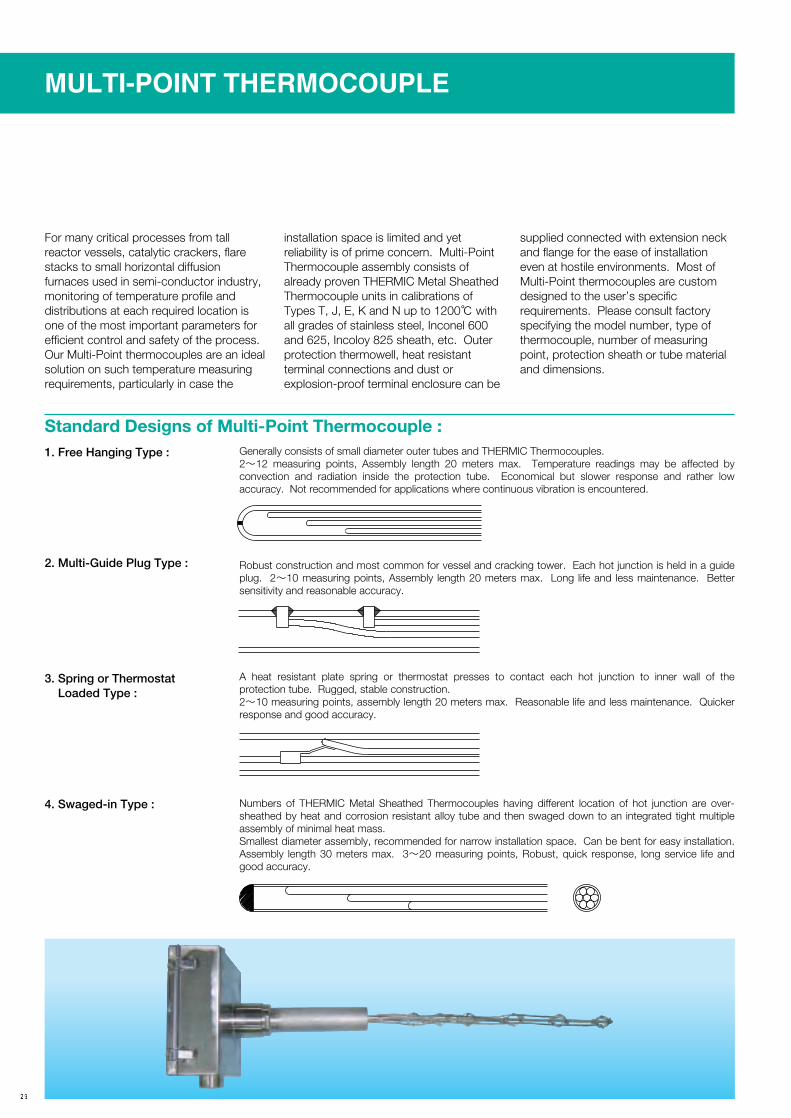
MULTI-POINT THERMOCOUPLE
Standard Designs of Multi-Point Thermocouple :
For many critical processes from tall reactor vessels, catalytic crackers, flare stacks to small horizontal diffusion furnaces used in semi-conductor industry, monitoring of temperature profile and distributions at each required location is one of the most important parameters for efficient control and safety of the process. Our Multi-Point thermocouples are an ideal solution on such temperature measuring requirements, particularly in case the
installation space is limited and yet reliability is of prime concern. Multi-Point Thermocouple assembly consists of already proven THERMIC Metal Sheathed Thermocouple units in calibrations of Types T, J, E, K and N up to 1200℃ with all grades of stainless steel, Inconel 600 and 625, Incoloy 825 sheath, etc. Outer protection thermowell, heat resistant terminal connections and dust or explosion-proof terminal enclosure can be
supplied connected with extension neck and flange for the ease of installation even at hostile environments. Most of Multi-Point thermocouples are custom designed to the user’s specific requirements. Please consult factory specifying the model number, type of thermocouple, number of measuring point, protection sheath or tube material and dimensions.
Generally consists of small diameter outer tubes and THERMIC Thermocouples.2〜12 measuring points, Assembly length 20 meters max. Temperature readings may be affected by convection and radiation inside the protection tube. Economical but slower response and rather low accuracy. Not recommended for applications where continuous vibration is encountered.
1. Free Hanging Type :
Robust construction and most common for vessel and cracking tower. Each hot junction is held in a guide plug. 2〜10 measuring points, Assembly length 20 meters max. Long life and less maintenance. Better sensitivity and reasonable accuracy.
2. Multi-Guide Plug Type :
A heat resistant plate spring or thermostat presses to contact each hot junction to inner wall of the protection tube. Rugged, stable construction.2〜10 measuring points, assembly length 20 meters max. Reasonable life and less maintenance. Quicker response and good accuracy.
3. Spring or Thermostat Loaded Type :
Numbers of THERMIC Metal Sheathed Thermocouples having different location of hot junction are over-sheathed by heat and corrosion resistant alloy tube and then swaged down to an integrated tight multiple assembly of minimal heat mass.Smallest diameter assembly, recommended for narrow installation space. Can be bent for easy installation. Assembly length 30 meters max. 3〜20 measuring points, Robust, quick response, long service life and good accuracy.
4. Swaged-in Type :

HIGH TEMPERATURE MULTI-POINT THERMOCOUPLE
Standard Designs of High Temp. Multi-Point Thermocouple :
measurement of temperature profile in a diffusion furnace of semi-conductor industry. Due to limitation of the furnace inlet, 2〜5 points assembly is prevailed. For special applications, Silicon Carbide outer protection tube can be used. Please consult our factory.
For temperature range of above 1200℃ upto 1450℃, where metal sheathed compacted MgO type thermocouple can no longer be used as well as any of super-alloys, Platinum-Rhodium group thermocouples of Types S, R and B are used with high purity Quartz protection tubes and Alumina insulators. At present major applications of such a High Temperature Multi-point Thermocouple seems to be concentrated for use on
High Purity Quartz, Alumina and Special SiC tubeType R, S and B2〜5 max.Type R and S 1200℃ (Quartz Tube), Type B 1600℃ (Alumina Tube)1〜2 meters12〜25 mm.Standard Grade ±0.25% of Reading.Premium Grade±0.1% of Reading (Type R only)*SiC tube is optional, but sometimes needs to protect thermocouple wires from contamination by inner protective coating or clean Alumina inner tube, etc.
Specifications are same as above, but the cold end of the protection tube is bent approx. 90 Deg. to fit for limited installation space.
Protection Tubes Thermocouple Measuring pointsMeasuring rangeLength of AssemblyOverall Dia. of Assembly Accuracy
:::::::
1. Straight Quartz or Alumina Tube protected Type :
2. Bent protection Tube Type :
T/C No.1 T/C No.2 T/C No.3 T/C No.4
T/C No.1 T/C No.2 T/C No.3 T/C No.4

HT-THERMIC (MODEL : HT, HT-270A)
● Max. Temp. 2,000℃, 1% Accuracy of the Reading● For use in Inert, Reducing (H2) and Vacuum Applications● Patented Special Hot Junction● Electron Beam weld closed Protection Tube, filled with Pure Dry Argon Gas ● Perfectly Integrated Robust Construction
MODEL HT
● Max. Temp. 1,500℃, A Heavy Duty, Flame-Proof Version of already proven Model HT● 1% Accuracy of the Reading● The only High Temperature Thermocouple for use both in dry Oxidizing and Reducing environments where all the platinum group thermocouples fail● No need of expensive gas purging, successfully be used for a long-term under dry stagnant atmospheres● Unique Triple protection and Flame-Proof Safety Construction● Avoid use under wet or water-vapour rich conditions
MODEL HT 270A
ULTRA HIGH TEMPERATURE THERMOCOUPLE
R

Descriptions of HT-THERMIC
ULTRA-HIGH TEMPERATURE THERMOCOUPLEFOR 1,500℃ AND 2,000℃ MAX.
HT-THERMIC
Standard Types of HT-THERMIC
HT-THERMIC is a trade name of inert gas filled thermocouple for use under super-high temperatures. HT-THERMIC was first developed in Japan by YAMARI through unique process and is enjoying good reputation as a prominent sensor for the
use in high temperature heat treatments and sinterings, etc. because of its capability of measuring temperatures up to 2,000℃ for a long-term with an excellent stability.Based-on the technology of HT-THERMIC, YAMARI manufactures various
sophisticated thermocouples for high temperature measurement to the customer's needs. HT-THERMIC will exceed foreign products in all respect of cost merit, quality and performance.
L
φD
41 68
Unit : mm
Unit : mm
Unit : mm
Unit : mm
L
φD φ12
High Temp. Cement
150 68
φD
1050L A
φ8 φ3.2
φD φ16
70 AL
HT. 1
HT. 2
HT. 3
HT. 4
HT1 -
Type
W5Wire
- BE300(PS0)
Insulation Material(Tip300mm, Rest PSO)
- -
Protection TubeMaterialO.D.
/ TCF642CompressionFitting
LLength
CodeSample : MO 64
HT2 -
Type
BWire
- -PS0 PT0InsulationMaterial
-
Protection TubeMaterialO.D.
/ MCF123CompressionFitting
LLength
CodeSample : 8
HT3 -
Type
W5Wire
- -PS0InsulationMaterial
-
Protection TubeMaterialO.D.
/MI CableLength
LLength
CodeSample : 48MO
HT4 -
Type
W5Wire
- -PS0InsulationMaterial
-
Protection TubeMaterialO.D.
/MI CableLength
LLength
CodeSample : 16NB
A
A
R

HT-THERMIC (MODEL : HT, HT-270A)
1 Thermocouple conductors
W5
+leg -leg
ASTM E 988-1990±1.0% of
reading
0.5
0.25
0.5
HT1・HT2・HT3
HT4
HT2
0〜2,300℃
CompositionStandards Class Tolerance
WireDia. (mm)
ApplicableAss’y Type
OperatingTemperature
2 InsulatorsCode
PSO
BE
MG
MaterialRecrystallized
Alumina(Al2O3)
RecrystallizedBeryllia(BeO)
SinteredMagnesia
(MgO)
Max.Temp.
1,800℃
2,200℃
2,200℃
※Max. Temp. varies depending on operating atmospheres.
4 Compression Fittings
3 Protection TubesCode
MO
TA
NB
PTO
BE
ZR
Material
Molybdenum
Tantalum
Niobium
RecrystallizedAlumina(Al2O3)
RecrystallizedBerylia(BeO)
Non-porousZirconia
Max. Temp.
1,700℃
2,200℃
2,000℃
1,800℃
2,200℃
2,200℃
Max.Length
1,000
1,000
1,000
1,000
500
600
O.D.6.44.81.64.81.64.81.6
8.0
6.4
6.4
Ass’y TypeHT1・HT3HT1・HT3
HT4HT1・HT3
HT4HT1・HT3
HT4
HT2
HT2
HT2
CodeTCF 481TCF 482TCF 642
D4.84.86.4
SR1/8R1/4R1/4
L333535
Mat : 304S.S. Ass’y : HT1Code
LCF 481LCF 482LCF 642
D4.84.86.4
SR1/8R1/4R1/4
L333535
Mat : 304S.S. Ass’y : HT1Code
MCF 123MCF 124MCF 126
D121212
SR3/8R1/2R3/4
L526060
Mat : 316S.S. Ass’y : HT2
Unit : mm
8 MI Compensating Cable
6 Mid. Temp. Transition 7 Low Temp. Transition
For use in vacuum or atmospheric gases.Max. 260℃
Metal sheathed compensating cable exclusive for W/Re thermocouples. Excellent heat and corrosion resistance.
Bendable up to 4 times ofits radius. Can compensateemf as high as 260℃ withintolerance of ±0.11 mV (±8℃).
For use in the air outside furnaces.Epoxy resin is filled in S.S. sleeve to prevent moisture absorption.Max. 120℃
Type
W5
Oper. Temp.
0〜260℃
Tolerance
±0.11 mV
5 D-Type Connector
9 Compensating Cable
Exclusive use for W/Re thermocouples. Element wires are covered with braided glass yarn. Capable of connecting to types HT1, HT2, or HT3. tolerance : ±0.11 mV for W5. Max. 200℃.
Glass Braided Insulation
±4℃ or 0.5%±0.5%
0.5Standard
600〜1,700℃870〜1,700℃
JIS C 1602ASTM E 230
W26%Re
Pt6%Rh
W5%Re
Pt30%Rh
Type
B
S
L
D
Teflon S
L
D
30
25.3
12.5
11
38 50
φ3.2φ8
Mg0
φ3.2
Wires
Sheath 347S.S.
Wiresφ0.5
3
2
Glass fiber Insulator
Glass covering
S
L
D
LAVA
55
φ8
Unit : mm
Unit : mm
R

HT-THERMIC Thermoelement Wires, Insulators and Protection Tube
HT-THERMIC
It is common that between constituent materials and elements, unexpected chemical reactions and dissociations repeatedly occur in various furnaces and vessels at high temperatures, and even at low temperatures, vacuum or reducing atmospheres often facilitate formation of
unstable compounds. On the side of thermocouple itself, contact reactions between constituent materials either in solid or vapour-phase often occur and, finally, thermocouple is deteriorated. These phenomena are greatly accelerated by the presence of even a trace
amount of oxygen, moisture, and contaminants. Proper selection of materials is, therefore, the key factor determining the performance and service life of thermocouples.
Thermoelement WiresThermoelement wires for HT-THERMIC are carefully selected by considering the measuring conditions and temperature range. For temperatures up to 1,700℃, Type B (Pt30%Rh/Pt6%Rh) thermoelement wires are
used, and for the temperatures up to 2,000℃, Tungsten/Rhenium (Types W5) thermoelement wires are used. For critical environments such as nuclear applications, special thermoelement wires, Pt5%Mo/Pt0.1%Mo, Pt6%Ru/Pt,
Mo-Nb, Ni18%Mo/Ni may be used upon prior arrangements.
InsulatorsFor use at high temperatures (over 1,200℃), sintered high purity insulating tubes of Alumina
or Beryllia are used because resistivity of MgO or Al2O3 powder insulator drops badly at these
high temperatures.
In order to prevent embrittlement and improve mechanical strength, Rhenium was added to the both legs. Type W5 thermoelement wires are not embrittled up to 1,650℃ and, by
annealing, problem of initial EMF shift as experienced with the early Tungsten-Rhenium wires (W/W26%Re) is solved. Type W5 thermocouple can be used in nuclear
applications at high temperatures but not to be used in air or other oxidizing atmospheres because of its strong affinity to oxygen.
(W5%Re/W26%Re) : For reducing, inert, vacuum atmospheres.W5
As to details of Type B, refer to Page 7. Type B thermocouple is recommended for use under air and oxidizing atmospheres, but not suitable for any nuclear application because Rhodium
has a large neutron absorption cross section and easily transmutes to Palladium. Type B should not be used under reducing atmosphere, as constituent platinum group
metals absorb Hydrogen causing volume expansion and embrittlement.
(Pt30%Rh/Pt6%Rh) : For oxidizing and inert atmospheres.B
Characteristics of Thermoelement Wires
Type
W5
B
Composition
W5%ReW26%Re
Pt30%RhPt6%Rh
OperatingTemp.
0〜2,300℃
600〜1,700℃
MeltingPoint
3,350℃
3,120℃
1,927℃
1,826℃
EMF (μV)
8.8/℃at 2,316℃
11.7/℃at 1,600℃
Coeff. of Thermal Expansion-
3.9×10⁻⁶/ 20〜1,983℃
8.9×10⁻⁶/ 20〜1,800℃
9.1×10⁻⁶/ 20〜1,800℃
Resistivity(μΩ/cm)
18.0/0〜100℃
30.9/0〜100℃
19.0/0〜100℃
17.5/0〜100℃
Standards& Accuracy
ASTM E 988±1%
ASTM E 230JIS C 1602±0.5%
Characteristics of Insulating Tubes
Code
PSO
BE
MG
Composition
RecrystallizedAlumina
RecrystallizedBerylliaSintered
Magnesia
Purity
>99.7%Al2O3
>99.5%BeO
>99.5%MgO
MaximumTemperature
1,800℃/1KΩ・cm
2,000℃/1KΩ・cm
2,200℃/1KΩ・cm
MeltingPoint (℃)
2,050±20
2,550±20
2,800±20
Specific Heat(Caℓ/℃)
0.26/20〜1,000℃
0.50/20〜1,000Ω
0.25/20〜1,000Ω
Thermal Conductivity(Caℓ/・cm-1・℃-1・S-1)
0.014/1,000℃
0.046/1,000℃
0.016/1,000℃
R

HT-THERMIC (MODEL : HT, HT-270A)
R
Protection TubesSelection of appropriate protection tube is the most important factor that practically determines reliability and service life of the thermocouple. Therefore, extensive
knowledge is required on environmental conditions especially at high temperatures where complicated and serious chemical reactions often occur between
thermocouple materials and environments.
Materials and Their Characteristics
Code
MOTANB
PT0
BE
ZR
Material
Molybdenum (Mo)Tantalum (Ta)Niobium (Nb)RecrystallizedAlumina (Al2O3)RecrystallizedBeryllia (BeO)Non-Porous
Zirconia (ZrO2)
MeltingPoint (℃)2,622±102,850±102,415±15
2,050±20
2,550±20
2,300±20
Max. Temp.℃
2,1002,1002,000
1,800
2,200
2,100
CompatibleAtmosphere
V・R・NV・N (Ar・He)V・N (Ar・He)
R・N・O
V・R・N・O
N・O
Linear Coeff. ofExpansion (×10-6)
7.2/2,000℃6.6/2,000℃9.0/2,000℃
8.6/1,000℃
8.9/1,000℃
10.0/1,000℃
Thermal Conductivity(Caℓ/・cm-1・℃-10・S-1)
0.3280.1300.132
0.014
0.046
0.010
Note : V=Vacuum, R=Reducing, N=Inert, O=Oxidizing.
Note : *Values in 10-4 torr vacuum. In protective atmospheres, lower by 100〜200℃.
Stability of Heat-Resistant Metals in Various AtmospheresAtmosphereAir or oxygen
contained gasesDry hydrogen
(abt 0.5g H2O/m3)Damp hydrogen(abt 20g H2O/m3)
Crackeddry NH3
Incompletelycombusted dry
NH3
Dry inert gases(argon, helium, etc.)Vacuum : 10-3 torr
10-4 torrCompatible
Atmospheres
Molybdenum400〜500℃ : Oxidized.Over 800℃ : Vaporized
No reaction up to melting point.
Up to 1,400℃ : No oxidizing but hence, needle crystals grow.
No corrosion up to melting point.
〃
〃
Up to 1,700℃ : No corrosion.Over 1,800℃ : Heavily vaporized.
High temperature reducing and inert gases and low vacuum (no oxygen).
NiobiumOver 200℃ : Oxidized
and nitrides grow.200℃ : Hydrogen absorbed.
1,900℃ : Hydrides grow and embrittled.200℃ : Hydrogen absorbed.
1,900℃ : Hydrides grow and embrittled.Over 200℃ : Hydrides and nitrides grow.
Over 200℃ : Hydrides grow.
Over 400℃ : NH3 decomposed and nitrized.
In helium at 1,900℃ : Crystals grow and embrittled.
Embrittled due to "getter effect".Small evaporation up to melting point.
Inert gases, high temperature and vacuum up to 900℃, especially in Na and Li.
TantalumOver 500℃ : Oxidized
and nitrides grow400〜800℃ : Hydrides grow.
No corrosion up to melting point.Over 450℃ : Hydrides grow
heavily and oxidized.Over 400℃ : Nitrides and hydrides grow.
Then, completely nitrized.
〃
No corrosion up to melting point.
Embrittled due to "getter effect".Over 2,200℃ : Heavily vaporized.
Inert gases, high temperature high vacuum (no oxygen).
Reactions between Metals and Refractories (Insulators) at high temperatureRefractories or Insulators
Graphite
Al2O3
BeO
MgO
ZrO2
ThO2
SilimaniteChamotte BrickMagnesite Brick
Molybdenum
Over 1,200℃ : Rapidly carbides grow.
Up to 1,900℃ : No reaction.Up to 1,900℃ : *No reaction.
Up to 1,800℃ : *No reaction.
Up to 1,900℃ : *No reaction buthevily Mo vaporized.
Up to 1,900℃ : *No reaction.Up to 1,700℃ : No reaction.Up to 1,200℃ : No reaction.Up to 1,600℃ : No reaction.
Tantalum
Over 1,000℃ : Rapidly carbides grow.
Up to 1,900℃ : No reaction.Up to 1,600℃ : No reaction.
Up to 1,800℃ : No reaction.
Up to 1,600℃ : No reaction.
Up to 1,900℃ : No reaction.Up to 1,600℃ : No reaction.Up to 1,200℃ : No reaction.Up to 1,500℃ : No reaction.
Tungsten
Over 1,400℃ : Rapidly carbides grow.
Up to 1,900℃ : No reaction.Up to 2,000℃ : No reaction.
Up to 2,000℃ : No reaction but heavily MgO vaporized.
Up to 1,600℃ : No reaction.
Up to 2,200℃ : No reaction.Up to 1,700℃ : No reaction.Up to 1,200℃ : No reaction.Up to 1,600℃ : No reaction.

MODEL HT-270A, A NEW FLAME-PROOF TYPE HIGH TEMPERATURE THERMOCOUPLE COMPATIBLE WITH ALL THE DRY ATMOSPHERES
HT-THERMIC R
Since introduction of Model HT High Temperature Thermocouple in 1972 for long term use under high temperature reducing and inert atmospheres, continued research work has been made to develop more versatile, heavy duty thermocouple Model HT-270A as based on the technology and expertise accumulated through the success of HT Series.
New patented Model HT-270A has greatly enhanced safety and reliability for high temperature measurement up to 1500℃ under various hostile environments. If only the gas is dry, it can be used successfully in Oxidizing, Reducing, Inert and Sulphur or Chlorine bearing atmospheres without complicated costly gas-purge system hitherto needed on Platinum-Rhodium group thermocouples.
If water vapour is not present, virtually there is no limitation in atmospheres at the location. It was reported that two units of HT-270A had been used in a Sulphur Recovery Plant of the leading Petroleum Refinery, and after two years service, they were still within the specified tolerance, whereas competitions had all failed in a few months.
Specifications :Tungsten 5% Rhenium vs. Tungsten 26% Rhenium, 0.5 mm O.D.Non-embrittled Cold Forming High Purity BeO and AluminaPure Dry Argon filled Mo/Alumina/Impervious ceramic
Thermocouple Wire
Hot JunctionInsulating Tubes Protection Tubes
:
:::
Flame-proof, Equivalent to CenelecExd II CT6Stainless Steel0〜1500℃(Oxidizing) 0〜1600℃(Reducing, Inert and Vacuum)1% of Reading
Terminal Enclosure
Metal FittingsMeasuring Temp.
Rated Accuracy
:
::
:
CODE : HT-270A Screwed-in Type
CODE : HT-270A Flanged Type

THERMOWELL (MODEL : WL)
Thermowells which are made of solid bar stock of various heat and corrosion resistant alloys by drilling are usually preferred over the tip welded protection tubes for critical applications where high mechanical strength and longer service life are required. If the alloy bar material is correctly selected and designed properly, the Thermowell lasts long against corrosives, high pressure, high temperature, mechanical shock and vibration that may result from high velocity of fluids. In order to offer the best and safest Thermowells against Ka'rma'n’s Turbulence and other stresses, automatic calculations of mechanical strength to fluid pressure and flow velocity to estimate frequency of critical resonance are made by a specially developed computer programme as based upon operating conditions at the site. At YAMARI, thermowells are manufactured by a genuine Two-Shaft Gun Drilling Machine of 2- metre max. depth and the latest NC Turning Machines.
Standard Alloy Bar Materials :Stainless Steel* 304, 321, 316, 347, 310, 446, 253MAInconel 600, 601, 625, X-750Incoloy 800, 825Hastelloy B, C276, XOthers Haynes 25, Carpenter 20Cb, Nichrome, HCF, 50Co-30Cr, Monel,Brass, Bronze, Titanium, Tantalum, Molybdenum*Low carbon types of Austenite S.S. are available on request.
Standard Sizes of Solid Bar Materials :Round Bars : mm O.D.25, 26, 28, 30, 32, 34, 36, 38, 40, 46, 48, 50, 55
Hexagonal Bars : mm Width across Flats26, 29, 32, 35, 38, 41, 48, 50, 55
Tests and Inspections●Pressre Test : N2 gass pressure test up to 10MPa is conducted upon request.
●Hydrostatic Pressure Test : Internal pressure test up to 40MPa is conducted upon request.
●X-Ray Inspection : X-ray inspection for uniformity in wall thickness, eccentricity of bore and smooth inner finish are also conducted upon request.
●Optional : Helium leak Test Dye penetrant Test Cross checking of material with Mill Certificate

THERMOWELL
Standard Bores and DepthsBore Dia. (mm)
4.0
5.5
7.0
8.5
10.0
11.0
12.0
16.0
Max. Depth (mm)
500
700
800
1000
1200
1200
1200
1200
Standard Alloy Bar Materials :Stainless Steel* 304, 321, 316, 347, 310, 446, 253MAInconel 600, 601, 625, X-750Incoloy 800, 825Hastelloy B, C276, XOthers Haynes 25, Carpenter 20Cb, Nichrome, HCF, 50Co-30Cr, Monel,Brass, Bronze, Titanium, Tantalum, Molybdenum*Low carbon types of Austenite S.S. are available on request.
Standard Sizes of Solid Bar Materials :Round Bars : mm O.D.25, 26, 28, 30, 32, 34, 36, 38, 40, 46, 48, 50, 55
Hexagonal Bars : mm Width across Flats26, 29, 32, 35, 38, 41, 48, 50, 55
Tests and Inspections●Pressre Test : N2 gass pressure test up to 10MPa is conducted upon request.
●Hydrostatic Pressure Test : Internal pressure test up to 40MPa is conducted upon request.Internal pressure test up to 40MPa is conducted upon request.
●X-Ray Inspection : X-ray inspection for uniformity in wall thickness, eccentricity of bore and smooX-ray inspection for uniformity in wall thickness, eccentricity of bore and smooth inner finish are also conducted upon request.
●Optional : Helium leak Test Dye penetrant Test Cross checking of material with Mill Certificate
Standard Sizes of Solid Bar Materials :Round Bars : mm O.D.25, 26, 28, 30, 32, 34, 36, 38, 40, 46, 48, 50, 55
Hexagonal Bars : mm Width across Flats26, 29, 32, 35, 38, 41, 48, 50, 55
Tests and Inspections●Pressre Test : N2 gass pressure test up to 10MPa is conducted upon request.
●Hydrostatic Pressure Test : Internal pressure test up to 40MPa is conducted upon request.
●X-Ray Inspection : X-ray inspection for uniformity in wall thickness, eccentricity of bore and smooth inner finish are also conducted upon request.
●Optional : Helium leak Test Dye penetrant Test Cross checking of material with Mill Certificate
Standard Alloy Bar Materials :Stainless Steel* 304, 321, 316, 347, 310, 446, 253MAInconel 600, 601, 625, X-750Incoloy 800, 825Hastelloy B, C276, XOthers Haynes 25, Carpenter 20Cb, Nichrome, HCF, 50Co-30Cr, Monel,Brass, Bronze, Titanium, Tantalum, Molybdenum*Low carbon types of Austenite S.S. are available on request.

THERMOWELL (MODEL : WL)
Models of Solid Bar-stock Thermowell Model:WL
2
3
4
5
6
7
565
Hex17※2045U
B
B2
D2 S
P
BD2
P
S
Hex
D1
517
※25 TU
D1
P
P
S
S
Hex17
※25 20TU
D1BD2
5
17※2550U
5
Hex
BD2
D1 N
25
P
P
S
S N
17
17
20
※25
※20
50U
U T
5
Hex
W
BD2
D1
B2
N1
65
B
5
D2D1
5
Hex17※2045U
BD2 S
P
D1
1Hexagonal Screwed-inType
WL・01
Hexagonal Screwed-in Type
WL・11
Hexagonal Lagging Extension Type
WL・12
WL・01 316 250/
- -
Model No. Material316SS
18"D1"Dia. For TaperedWell Only
45/※20/29×33.5HexFactory Standard UnlessOtherwise Specified
"U"Length
"P"Thread Std.
"B"Bore "D2"Dia.
- 9-R1/2
"S"ThreadStd.
Rc1/2
/ 15/ ×
※Thread Allowance
OrderCode :
WL・11 304 300/
- -
Model No. Material304SS
21"D1"Dia. For Tapered Well Only
45/※20/35×40.4HexFactory Standard Unless Otherwise Specified
"U"Length
11"B2"Dia."P"Thread
Std."B"×LengthBore Size
- 8.5×65-R3/4
"S"ThreadStd.
Rc1/2
/ /
17"D2"Dia.
/ ×
※Thread Allowance
OrderCode :
WL・12 310 450/
- -
Model No. Material310SS
75"T" Length
※25/38×43.9HexFactory Standard Unless Otherwise Specified
"U"Length
11"B" Bore
17"D2"Dia."P"Thread
Std.
- -R1
"S"ThreadStd.
Rc1/2
/ / ×
26"D1"Dia. For TaperedWell Only
/ ×
※Thread Allowance
OrderCode :
Hexagonal Lagging Extension Type
WL・02 WL・02 321 300/
× - -
Model No. Material 321SS
75"T" Length
34"N"Dia.
※25/34/41×47.3HexFactory Standard Unless Otherwise Specified
"U"Length
11"B" Bore
17"D2"Dia."P"Thread
Std.
- -NPT1
"S"ThreadStd.
Rc3/4
/ / ×
26"D1"Dia. For TaperedWell Only
/ ×
※Thread Allowance
OrderCode :
Hexagonal HeavyDuty Type
WL・21 WL・21 321 350/
× - -
Model No. Material 321SS
11-
"B" Bore
17"D2"Dia.
26"D1"Dia. For Tapered Well Only
34"N"Dia.
※50/25/50×57.7HexFactory Standard Unless Otherwise Specified
"U"Length
-
"S"ThreadStd.
Rc3/4
"P"ThreadStd.
R11/2/ /
×
※Thread Allowance
OrderCode :
Hexagonal Heavy Duty Type
WL・22 WL・22 316 400/
× × - -
Model No. Material316SS
11Bore Size
7×65-
"B"×Length
17"D2"Dia.
26"D1"Dia. For Tapered Well Only
34"N"Dia.
※50/25/35×40.4HexFactory Standard Unless Otherwise Specified
"U"Length
-
"S"ThreadStd.
Rc1/2
"P"ThreadStd.
R1/ /
/
※Thread Allowance
OrderCode :
Screwed-in Weld Type
WL・04 WL・04 304/
× -
Model No. Material316SS
300"U"Length
11"B"Bore
-
21"D1"Dia. For Tapered Well Only
28-※20"N"Factory Standar Unless Otherwise Specified
-
75"T"Length
-
"S"Thread Std.
Rc1/2
"P"ThreadStd.
/R3/4/ 17"D2"Dia.
/ ×
※Thread Allowance
OrderCode :
N

THERMOWELL
Other special types are also available upon request
8
9
10
11
12
13
14
5
UP 17
50
S NBD2D1
5
U1750
S NBD2D1
565
U1750
S NBD2
S N
D1
B2
BD2
517
U T
S NBD2
517
U 50
S N
S N
BD2D1D R
T
R
1775
5
U
35゜
17Q65
5
U
D1DBD2
Flanged (Screwed-in) Type
WL・05 WL・05 304 500/
/ / - -
Model No. Material 304SS
21"D1"Dia. For TaperedWell Only
11"B"Bore
×17"D2"Dia.
304Material304SS
50×34Neck DimensionLength×"N"Dia.
"U"Length
"P"Thread Std.
Flange Rating
- -JIS10K25ARF/R3/4
"S"Thread Std
Rc1/2
/ /OrderCode :
Flanged (Weld) Type
WL・06 WL・06 316 1250/
/ / - -
Model No. Material 316SS
18"D1"Dia. For TaperedWell Only
9"B"Bore
×15"D2"Dia
316Material 316SS
50×28Neck DimensionLength×"N"Dia.
"U"Length
Flange Rating
- JIS10K20ARF
"S"Thread Std
Rc1/2
/ /OrderCode :
Flanged (Weld) Type
WL・61 WL・61 316 600/
/ / - -
Model No. Material 316SS
26"D1"Dia. For TaperedWell Only
11"B2"Bore
×17"D2"Dia
316Material 316SS
50×34Neck DimensionLength×"N"Dia.
8.5×65"B"×LengthBore Size
"U"Length
Flange Rating
- ANSI1"600LBRF
"S"Thread Std
Rc1/2
/ / -OrderCode :
Plain Weld Type
WL・07 WL・07 304 300/
/
Model No. Material304SS
250×30Neck DimensionLength×"N"Dia.
"U"Length
9"B"Bore
- - 17"D2"Dia.
/ -OrderCode :
"S"Thread Std
Rc1/2
Weld Type
WL・08
Ball Joint Type
WL・09
WL・08 321 500/
/
Model No. Material 321SS
50×41Neck DimensionLength×"N"Dia.
"U"Length
11"B"Bore
- - 22"D2"Dia.
25"D1"Dia. For Tapered Well Only
/ - -OrderCode :
"S"Thread Std
Rc1/2
WL・09 316 1300/
-
Model No. Material 316SS
10"B"Bore
75×26.6Neck DimensionLength×"N"Dia.
"U"Length
25.4R×34.9D×3.2TBall Joint Dimension"R"×"D"×"T"
-
/ 14.3"D2"Dia.
19"D1"Dia. For Tapered Well Only
/ -
/ -OrderCode :
"S"Thread Std
NPT1/2
Van Stone Type
WL・10 WL・10 304 250/ /
-
Model No. Material 304SS
11"B"Bore
17"D2"Dia.
65×34Neck DimensionLength×"N"Dia.
"U"Length
50×6.5Raised Face "D"×"Q"
-
/ 26"D1"Dia. For TaperedWell Only
/
/ -OrderCode :
"S"Thread Std
Rc1/2
D1
THERMOWELL (MODEL : WL)
BLIND FLANGES
JIS FLANGEFLAT FACE (FF) RAISED FACE (RF)
Dimensional Specifications Unit : mm
Size A
15202532401520253240
Flange Rating
JIS 5K
JIS 10K
Size B
1/23/41
11/411/21/23/41
11/411/2
D
80859511512095100125135140
t
9101012121214141616
f
1112211122
g
44495970755156677681
C
6065759095707590
100105
f
1112211122
No. of Bolt Holes
4444444444
Bolt Size
M10M10M10M12M12M12M12M16M16M16
Nom. Weight(kg)
0.320.410.520.910.990.630.781.221.661.80
Hole Dia.12121215151515191919
ANSI FLANGERAISED FACE (RF) RING JOINT (RTJ)
RAISED FACE (RF) RING JOINT (RTJ)
Dimensional Specifications Unit : mm
Size A
15202532401520253240
Flange
ANSI 150lbs
ANSI 300lbs
Size B
1/23/41
11/411/21/23/41
11/411/2
D
899910811712795117124133155
Min.t
11.513.014.516.018.014.516.018.019.521.0
f
1.61.61.61.61.61.61.61.61.61.6
g
35.142.950.863.573.235.142.950.863.573.2
C
60.569.979.288.998.666.582.588.998.6
114.5
No. of Bolt Holes
4444444444
X30.238.149.558.765.138.148.054.063.570.0
Min.K----
63.573.583.051.063.570.063.590.5
P----
74.6257.1565.0734.1442.8850.8060.3268.28
E----
6.46.46.46.46.46.46.46.4
Y16.016.018.021.022.422.425.427.027.030.3
HoleDia.15.815.815.815.815.815.819.019.019.022.4
Nom.Weight (Kg)
0.430.620.871.161.540.651.091.381.822.70
Bolt Size(inch)1/21/21/21/21/21/25/85/85/83/4
Hub RTJ
g
tf
CD
Hole
Fig.3
Fig.1 Fig.2
Fig.4
Fig.5 Fig.6
KP
t6.
4
CD
Hole
E
g
tf
CD
HoleX
Y
KP
X
t6.
4
CD
Hole
EY
t
C
D
Hole
tf
C
g
D
Hole

THERMOWELL
Types of Jointing Flanges with ThermowellFor the rigorous weld-joining requirements, skilled technicians are selected among the TIG welding workers at our factory who all have qualifications and license granted by Japan Welding Association and Japan Stainless Steel Society, and are exclusively
engaged in this precise job. The welding procedures and requirements generally follow to ASME Boiler Code QW 201.1〜2, WPS and PQR, JPI 7S-31, etc. Grooves on each flange are carefully determined and machined to primary "J"
or secondary Bevel shapes to enable perfect fillet welding. A serrated flange face can be machined. Please consult factory.
Dimensional Specifications Unit : mm
Size A
15202532401520253240
Flange
ANSI 400lbs&
600lbs
ANSI 900lbs&
1,500lbs
Size B
1/23/41
11/411/21/23/41
11/411/2
D
95117124133155121130149159178
Min.t
14.516.018.021.022.522.525.528.528.532.0
f
6.46.46.46.46.46.46.46.46.46.4
g
35.142.950.863.573.235.142.950.863.573.2
C
66.582.688.998.5
114.582.588.9
101.6111.3124.0
No. of Bolt Holes
4444444444
X38.148.054.063.570.038.144.552.563.570.0
Min.K51.063.570.079.590.560.567.071.581.592.0
P34.1442.8850.8060.3268.2839.6744.4550.8060.3268.28
E6.46.46.46.46.46.46.46.46.46.4
Y22.425.427.028.532.032.035.141.241.244.5
HoleDia.15.819.019.019.022.422.422.425.425.428.5
Nom.Weight (Kg)
0.761.271.592.243.301.792.403.443.955.41
Hub RTJBolt Size(inch)1/25/85/85/83/43/43/47/87/81
1. Groove welded Type
Commonly made to weld relatively lower rating flanges. At the upper edge or the both edges of center hole of the flange, groove(s) for fillet welding is provided. TIG or Plasma Arc Welders are normally used. It is essential that the clearance between
center hole of the flange and neck of the thermowell be kept minimal in diameters.
2. Full Penetration Weld Type
Suitable for flanges of medium to high rating. This fully welded joint has an excellent strength to high pressure and perfect integrity to liquid and gas leak. High degree of welding technique is employed for void-free welding job. For some of Stainless
Steel and alloy combinations, additional costs of post-weld heat treatment may be necessary for stress relief and restoring the original metal structure.
3. Threaded and Enlarged Neck Weld Type
Where the installation space permits, neck of the thermowell is machined to a larger diameter to provide curved edge at its bottom and positioned flush with flange face, so that the welded part may be shifted outward to prevent possible fatigue
from concentration of mechanical stress due to bending and vibration by virtue of the curved edge prepared on a heavier solid neck. This special design can be applied to the other types of welding joint.

EXTENSION & COMPENSATING CABLES
Types
Nowadays, thermocouples are being widely used in every industrial field from various chemicals, petro-refineries, metals, ceramics and electronics, nuclear to aerospace. Although it is theoretically ideal to have thermocouple connected directly to the
instrument, long distance between them often makes the wiring cost prohibitive and causes some trouble in the measuring circuit. Therefore, it is desirable to use extension or compensating wires or cables that have same or similar EMF characteristics to those of
thermocouples at ambient temperatures. It is also necessary to select insulation materials in accordance with the operating conditions.YAMARI have a large stock of various wires and cables as listed below and on pages 45.
Tolerances to JIS C1610-1995, IEC 584-3-1989
Insulation Resistance shall be more than 5MΩ/10 m.Notes : (1) BX has positive and negative legs of the same material (Cu), so no tolerance is stipulated. (2) These figures do not represent actual measuring error because Types R and S have non-linear EMF characteristics.* These color codes normally relate only to the compensating wire for use with the appropriate thermocouple conductor combination type code.
Thermo-coupleSymbol
Temp.Range℃
Codeof
YAMARI
ToleranceμV(℃)
Codes
B
K
N
E
J
T
IEC
JIS
IEC
JIS
IEC
JIS
IEC
JIS
IEC
JIS
JIS
IEC
JIS
IEC
JIS
IEC
JIS
BC
NX-1
NX-2
NC-2
±100(±2.5)
±100(±2.5)
0〜+100VX
0〜+100
0〜+150
WX
KX
NX
RX
BX
SX
-
EX-1
EX-2
±120(±1.5)
±200(±2.5)−25〜+200EX
JX-1
JX-2
±85(±1.5)
±140(±2.5)−25〜+200JX
−25〜+200±60(±1.5)
±100(±2.5)
KX-1
KX-2
KCA-2
KCC-2
KCB-2
−25〜+200
0〜+150
0〜+100
0〜+200
0〜+100
0〜+100
0〜+200
±100(±2.5)
±60(±1.5)
±100(±2.5)
±30(±2.5)
±60(±5.0)
{±40(±3.5)}
±30(±2.5)
±60(±5.0)
-
-
RCA-2
RCB-2
SCA-2
SCB-2
R
&
S
TX-1
TX-2
±30(±0.5)
±60(±1.0)−25〜+100TX
INSULATION COLOR CODES
JAPANJIS(DIV.2)
C1610-1995
U.S.AASTME230
U.K.BS
1843・1981
GERMANYDIN
43714
FRENCENF
NFE 18001
INTERNATIONALIEC 584-3(JIS DIV.1)
+ −
Black
Red White
+ −
Black
Red Black
+ −
Black
White Red
+ −
Black
Yellow Blue
+ −
Black
Yellow Black
+ −
Black
Black White
+ −
Green
Black Red
+ −
Green
White Blue
+ −
White
SX only
Red White
+ −
Green
SX only
Yellow Green
+ −
Green
Red Green
+ −
Green
Green White
+ −
Orange
Orange White
+ −
Blue
Red White
+ −
Yellow
Yellow Red
+ −
Yellow
Yellow Purple
+ −
Blue
Red White
+ −
Blue
Red White
+ −
Blue
Red Blue
+ −
Blue
Blue Red
+ −
Blue
White Blue
+ −
Blue
Yellow Blue
+ −
Purple
Red White
+ −
Purple
Purple White
+ −
White
Yellow White
+ −
+ −
Purple
Purple Red
+ −
Brown
Brown Blue
+ −
Brown
Red White
+ −
Brown
Brown White
+ −
Brown
Red Brown
+ −
Orange
Orange Red
+ −
Yellow
Red White
+ −
Orange
Orange Blue
+ −
Pink
Pink White
+ −
Red
Brown Blue
+ −
Red
Yellow Brown
+ −
Red
White Blue
+ −
Green
Green White
+ −
Gray
Red White
+ −
Gray
Gray Red
+ −
Gray
Red Gray
+ −
Gray
Gray White
±100(±2.5)
KX
WX
VX
Green
Green White

INSULATION MATERIALS FOR COMPENSATING WIRES AND CABLES
Note : Upper column indicates positive leg resistance ; middle column for negative leg resistance ; and lower column for loop resistance.
PVC Sheath :PVC insulation sheath has been widely used as a good substitute for rubber insulator. At YAMARI, PVC is used as an insulating material of standard compensating cables for general use.Recommended Temperature Range : -20〜+90℃
Glass Fiber Sheath :Glass fiber is known as a traditional high temperature insulation material because it has excellent incombustibility, heat resistance, electric insulation, and chemical stability.Although single glass fiber is not hygroscopic, bundled cover are somewhat hygroscopic. So, silicon or other resin is impregnated and baked over them to prevent moisture absorption.Recommended Temperature Range : 0〜150℃
Silicon Rubber Sheath :Silicon rubber has been widely used as an excellent insulation material with less deterioration physical properties even under hostile conditions.It has almost same electric properties as natural rubber and no serious change in voltage withstanding value occur over recommended temperature range. It has also good resistance to chemicals (except for concentrated Alkalis), oils and grease, outdoor and ozone environments.Recommended Temperature Range : -25〜+180℃
Teflon* (fluoric resin PTFE, FEP) Cover :Teflon is the best insulation material among organic materials in respect of heat resistance, chemical resistance, electrical insulation, high frequency resistance, weather resistance, etc. High mechanical strength and, especially, high pressure resistance over wider range of operating temperatures.Recommended Temperature Range : -25〜+200℃*Teflon is the registered trade mark by Dupont, U.S.A.
Metal Sheathed Compacted Mineral Insulation :The insulation material is fine grain MgO which is similar insulant to THERMIC Metal Sheathed Thermocouples. Inorganic ceramic powder insulation tightly holds extension or compensating wires inside the Metal Sheath, composing perfectly integral construction. This M.I. Extension or Compensating cable can withstand fire or high temperature, corrosion and mechanical shock and is approved as the only non-inflammable safety cable. Available in all calibrations with various metal sheath such as Copper, Cupro-Nickel, Stainless Steels, etc. Cable Sizes 1.6 mm〜8.0 mm O.D. Temperature Range : 20〜270℃, but the cable withstands high temperatures up to 900℃. Recommended for wiring at hazardous location without conduit tube.
EXTENSION & COMPENSATING
CABLES
Electrical ResistanceUnit : Ω/m.
RXSX KX WX VX EX JX TXBXNom. Cross-sec.
area A (mm2)
0.5
0.75
1.25
1.3
2.0
2.3
CoreNo. / Dia.
20/0.18
30/0.18
7/0.45
4/0.65or
1/1.37/0.6
or1/1.6
7/0.65
0.0340.0340.0680.0230.0230.0460.0140.0140.0280.0130.0130.0280.00850.00850.0170.00740.00740.015
0.0340.100.130.0230.0670.0900.0140.0400.0540.0130.0380.0510.00850.0250.0340.00740.0220.029
1.380.561.940.920.371.290.550.220.770.530.220.750.350.140.490.300.120.42
NX
1.920.762.681.280.501.780.770.301.070.740.291.030.490.190.680.420.160.58
0.240.460.700.160.310.470.0960.180.280.0920.180.270.0600.120.180.0520.100.15
0.0340.981.010.0230.650.670.0140.390.400.0130.380.390.00850.250.260.00740.210.22
1.380.982.360.920.651.570.550.390.940.530.380.910.350.250.600.300.210.51
0.240.981.220.160.650.810.0960.390.490.0920.380.470.0600.250.310.0520.210.26
0.0340.981.010.0230.650.670.0140.390.400.0130.380.390.00850.250.260.00740.210.22

EXTENSION & COMPENSATING CABLES
Standard Extension & Compensating CablesExtension and compensating cables listed below are manufactured in conformity with JIS C 1610-1995Cables can be supplied to other color codes and standards of ASTM, BS and DIN.
Code
BX1RX1SX1NX1KX1WX1VX1EX1JX1TX1
BX1ARX1ASX1ANX1AKX1AWX1AVX1AEX1AJX1ATX1ABX1BRX1BSX1BNX1BKX1BWX1BVX1BEX1BJX1BTX1BBX3RX3SX3NX3KX3WX3VX3EX3JX3TX3
BX3ARX3ASX3ANX3AKX3AWX3AVX3AEX3AJX3ATX3ABX3BRX3BSX3BNX3BKX3BWX3BVX3BEX3BJX3BTX3BBX4RX4SX4KX4WX4VX4EX4JX4TX4
Dimensions(mm)
Core0.65/7
Nom. finish8×5.2
Core0.65/7
Nom. finish8.6×5.8
Core0.65/7
Nom. finish8.5×5.35
Core0.65/7
Nom. finish6.5×3.4
Core0.65/7
Nom. finish7.1×4.0
Core0.65/7
Nom. finish6.8×4.3
Core0.2/40
Nom. finishφ9.8
Covering
Heat-resistantPVC insulating sheath.
Outer : Heat-resistantPVC sheath.
Inner : Copper shield.
Inner : Heat-resistantPVC sheath.
Outer : Copper shield.
Glass braided insulating sheath.
Outer : Glass braided insulating sheath.
Inner : Copper shield.
Inner : Glass braided insulating sheath.
Outer : Copper shield.
Heat-resistant rubber insulating sheath
ColorCodingGrey
Black
Pink
Blue
PurpleYellowBrownGrey
Black
Pink
Blue
PurpleYellowBrownGrey
Black
Pink
Blue
PurpleYellowBrownGrey
Black
Pink
Blue
PurpleYellowBrownGrey
Black
Pink
Blue
PurpleYellowBrownGrey
Black
Pink
Blue
PurpleYellowBrown
Black
Appearance

EXTENSION & COMPENSATING
CABLES
Code
BX4ARX4ASX4AKX4AWX4AVX4AEX4AJX4ATX4ABX4BRX4BSX4BKX4BWX4BVX4BEX4BJX4BTX4BBX5RX5SX5NX5KX5WX5VX5EX5JX5TX5BX6RX6SX6KX6WX6VX6EX6JX6TX6BX7RX7SX7NX7KX7WX7VX7EX7JX7TX7BX8RX8SX8KX8WX8VX8EX8JX8TX8
BX13RX13SX13NX13KX13WX13VX13EX13JX13TX13
Dimensions(mm)
Core0.2/40
Nom. finishφ11.4
Core0.2/40
Nom. finishφ11.2
Core0.65/4
Nom. finish4.8×7.5
Core0.45/7
Nom. finish4.6×7.1
Core0.65/4
Nom. finish5.6×3.3
Core0.45/7
Nom. finish5.0×3.0
Core0.3/7
Nom. finish4.6×2.8
Covering
Outer : Heat-resistant rubber insulating sheath.
Inner : Heat-resistant rubber sheath.
Outer : Copper shield.
Heat-resistant PVC insulating sheath
〃
Glass braidedinsulating sheath
〃
Inner : Glass braided insulating sheath.
Outer : Stainless steel shield.
ColorCoding
Black
Black
Grey
Black
Pink
Blue
PurpleYellowBrownGrey
Black
Blue
PurpleYellowBrownGrey
Black
Pink
Blue
PurpleYellowBrownGrey
Black
Blue
PurpleYellowBrownGrey
Black
Pink
Blue
PurpleYellowBrown
Appearance

EXTENSION & COMPENSATING CABLES
Code
BX13DRX13DSX13DNX13DKX13DWX13DVX13DEX13DJX13DTX13DBX14RX14SX14NX14KX14WX14VX14EX14JX14TX14
BX14DRX14DSX14DNX14DKX14DWX14DVX14DEX14DJX14DTX14DBX15RX15SX15NX15KX15WX15VX15EX15JX15TX15
BX15DRX15DSX15DNX15DKX15DWX15DVX15DEX15DJX15DTX15DBX15ARX15ASX15ANX15AKX15AWX15AVX15AEX15AJX15ATX15A
BX15ADRX15ADSX15ADNX15ADKX15ADWX15ADVX15ADEX15ADJX15ADTX15AD
Dimensions(mm)
Core0.3/7
Nom. finishφ5.3
Core0.3/7
Nom. finish4.0×2.3
Core0.3/7
Nom. finishφ4.5
Core0.3/7
Nom. finish4.1×2.4
Core0.3/7
Nom. finishφ5
Core
0.3/7
Nom. finish5×3.6
Core0.3/7
Nom. finishφ5.5
Covering
Inner : Glass braided insulating sheath.
Outer : Stainless steel shield.
Glass braided insulating sheath.
〃
Heat-resistant PVC insulating sheath.
〃
Outer : Heat resistant PVC insulating sheath
Inner : Copper shield.
〃
ColorCodingGrey
Black
Pink
Blue
PurpleYellowBrownGrey
Black
Pink
Blue
PurpleYellowBrownGrey
Black
Pink
Blue
PurpleYellowBrownGrey
Black
Pink
Blue
PurpleYellowBrownGrey
Black
Pink
Blue
PurpleYellowBrownGrey
Black
Pink
Blue
PurpleYellowBrownGrey
Black
Pink
Blue
PurpleYellowBrown
Appearance
Note : Other Color codings to ANSI or BS are available. Consult factory.
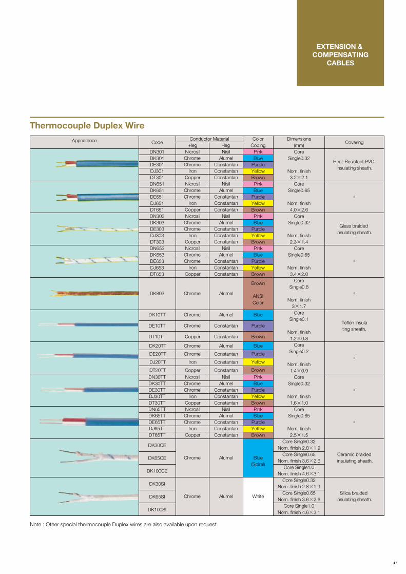
EXTENSION & COMPENSATING
CABLES
Code
DN301DK301DE301DJ301DT301DN651DK651DE651DJ651DT651DN303DK303DE303DJ303DT303DN653DK653DE653DJ653DT653
DK803
+legNicrosilChromelChromel
IronCopperNicrosilChromelChromel
IronCopperNicrosilChromelChromel
IronCopperNicrosilChromelChromel
IronCopper
Chromel
-legNisil
AlumelConstantanConstantanConstantan
NisilAlumel
ConstantanConstantanConstantan
NisilAlumel
ConstantanConstantanConstantan
NisilAlumel
ConstantanConstantanConstantan
Alumel
Dimensions(mm)Core
Single0.32
Nom. finish3.2×2.1
CoreSingle0.65
Nom. finish4.0×2.6
CoreSingle0.32
Nom. finish2.3×1.4
CoreSingle0.65
Nom. finish3.4×2.0
CoreSingle0.8
Nom. finish3×1.7Core
Single0.1
Nom. finish1.2×0.8
CoreSingle0.2
Nom. finish1.4×0.9
CoreSingle0.32
Nom. finish1.6×1.0
CoreSingle0.65
Nom. finish2.5×1.5
Core Single0.32Nom. finish 2.8×1.9
Core Single0.65Nom. finish 3.6×2.6
Core Single1.0Nom. finish 4.6×3.1
Core Single0.32Nom. finish 2.8×1.9
Core Single0.65Nom. finish 3.6×2.6
Core Single1.0Nom. finish 4.6×3.1
Covering
Heat-Resistant PVC insulating sheath.
〃
Glass braided insulating sheath.
〃
〃
Teflon insulating sheath.
〃
〃
〃
Ceramic braided insulating sheath.
Silica braided insulating sheath.
ColorCoding
PinkBlue
PurpleYellowBrownPinkBlue
PurpleYellowBrownPinkBlue
PurpleYellowBrownPinkBlue
PurpleYellowBrown
Brown
ANSIColor
Appearance
Note : Other special thermocouple Duplex wires are also available upon request.
Conductor Material
DN30TTDK30TTDE30TTDJ30TTDT30TTDN65TTDK65TTDE65TTDJ65TTDT65TT
DK30CE
DK65CE
DK100CE
DK30SI
DK65SI
DK100SI
DK10TT
DE10TT
DT10TT
DK20TT
DE20TT
DJ20TT
DT20TTNicrosilChromelChromel
IronCopperNicrosilChromelChromel
IronCopper
Chromel
Chromel
Chromel
Chromel
Copper
Chromel
Chromel
Iron
CopperNisil
AlumelConstantanConstantanConstantan
NisilAlumel
ConstantanConstantanConstantan
Alumel
Alumel
Alumel
Constantan
Constantan
Alumel
Constantan
Constantan
ConstantanPinkBlue
PurpleYellowBrownPinkBlue
PurpleYellowBrown
Blue(Spiral)
White
Blue
Purple
Brown
Blue
Purple
Yellow
Brown
Thermocouple Duplex Wire

EXPLOSION PROTECTION
EXPLOSION PROTECTIONDepending on the Class of hazardous area and the type of explosives, the following explosion protection can be specified with
the thermocouple assembly by considering installation space and measurement circuit wiring.
1. Flame-Proof Enclosure
Approved by KEMA:No. KEMA 03A TEX2002 X, II2G EEx de IIC T6...T1(for Temperature Sensors)No. KEMA 03A TEX2003, II2G EEx d IIC T6 (for Temperature Transmitters and Terminal Enclosure)To: EN 50014:1997, General requirements EN 50018:2000, Flameproof enclosure "d" EN 50019:2000, Increased safety "e" (for Temperature Sensors)
Approved by Research Institute of Industrial Safety, Ministry of Labor, Japan (R.I.I.S):Exd IIC T6No. C13997~C14002(for Temperature Sensors)No. C14391~C14396(for Temperature Sensors with Transmitters)
Yamari’s Flame-Proof Enclosure Model KG (II2G EEx d IIC T6/Ex d IIC T6/d2G4) has an approval label and certificate but limited in combination with Yamari’s thermocouple assembly. We can supply model KG Enclosure only, however, a certificate of approval and the safety label shall not be provided.
Material : ADC, Cast Iron & Cast SS
Caution :

OVERSEAS AFFILIATED COMPANIES
M.I. CABLE TECHNOLOGIES, INC. (MICT)EstablishmentAnnual TurnoverAddress
CapitalNumber of EmployeesMajor Businesses
October 1995CA$6,100,000Bay6, 5905-11th Street S.E. Calgary Alberta Canada T2H2A6TEL: 403-571-8266 FAX: 403-571-8267http://www.mict.ab.caCA$1,350,000.0033Manufacturing and Sales of Various Kinds of MI Thermocouple Cable, MI Extension Cable, MI Heat Tracing Cable
:::
:::
THERMOSENSOR TECHNOLOGIES PTE. LTD. (TST)EstablishmentAnnual TurnoverAddress
CapitalNumber of EmployeesMajor Businesses
Sales Area
November 1997S$4,500,00061 Tuas View Walk 2 Westlink Techpark Singapore 637630TEL: 065-268-0090 FAX: 065-262-0013http://www.thermosensor.comS$800,000.0033Manufacturing and Sales of Thermocouples, Resistance Temperature Detectors and ThermowellsSoutheast Asia except P.R.China, Taiwan, Korea
:::
:::
:

end. This enables to measure insulation resistance of the assembly very precisely between thermocouple conductors and sheath.
assembly immersed in a deep boiling water bath so as to accelerate condensation of moisture that might be entrapped in the assembly at the cold
INSPECTIONS AND TESTS
1. Appearance and Structure Check :
Visual inspection is made to confirm that the thermocouple assembly is in conformity with the specifications, drawing and constituent materials. Visual checkings are conducted on the finish of
joints, junctions, welds, name/tag plates and other parts to confirm that there is no error, flaw, dirt or irregularity on the surface finish.If necessary, dye penetration check,
hydrostatic pressure test and X-ray inspection shall be made on welded and joint parts.
2. Dimensional Check :
Unless otherwise specified, dimensional check is made in accordance with the following tables using Caliper, Straight Measure and Gauges.
3. Insulation Resistance Test
As one of the most important functions of Quality Assurance at YAMARI to comply with ISO 9001 Qualification, we are always striving for the improvement of Inspection and Test systems with their procedures including those of in-process quality check
and control. We maintain quality and accuracy records of our temperature products under established traceability with national standards as illustrated on page as the "Traceability System of Temperature Laboratory" accredited by
J.C.S.S. (Japan Calibration Service System). Specifications and procedures of inspection and testing generally follow or refer to the International Standards and Recommended Practices.
All the thermocouple units including beaded Type, THERMIC , HT-THERMIC and other custom-manufactured
assemblies are inspected and tested before delivery in accordance with the following procedures.
Insulation Resistance Test is conducted using a Super Megohmeter (max. scale 5 million MΩ) by applying steep temperature gradient on THERMIC Thermocouple
assembly immersed in a deep boiling water bath so as to accelerate condensation of moisture that might be entrapped in the assembly at the cold
end. This enables to measure insulation resistance of the assembly very precisely between thermocouple conductors and sheath.
4. Identification Test on the Thermocouple Type and Polarity
Either by dipping THERMIC thermocouple assembly into the above boiling water bath or applying hot air-blow/flame heat on the Beaded Thermocouple at its hot or cold
end to have it generate EMF, which allows to indicate specific type of thermocouple through Temperature vs. EMF Table. A high resolution D.C. circuit
testing instrument is used to identify the type of thermocouple and polarity of the thermocouple leg and terminal.
Nominal LengthBelow 1,0001,000〜2,000
Over 2,000
Tolerance±3.0±5.0±7.0
Beaded Type Unit : mm
Nominal LengthBelow 250250〜1,000Over 1,000
Tolerance±3.0±5.0±1.0%
THERMIC Unit : mmR
Note : In case of the THERMIC fabricated with protection tube or thermowell, the length within the tolerance of giving no functional trouble shall be regarded as passed.
Note : In case of the THERMIC fabricated with protection tube or thermowell, the length within the tolerance of giving no functional trouble shall be regarded as passed.
Voltage
DC 500V
DC 100V
DC 500V
Insulation Resistance
More than 10MΩ
More than 20MΩ
More than 100MΩ
I.R. In-Process at YAMARI
More than 1,000MΩ
More than 1,000MΩ
More than 1,000MΩ
R
Thermocouple
Beaded Type
THERMIC φ2.0 and below
THERMIC φ2.2 and above
R
R

end. This enables to measure insulation resistance of the assembly very precisely between thermocouple conductors and sheath.
assembly immersed in a deep boiling water bath so as to accelerate condensation of moisture that might be entrapped in the assembly at the cold
INSPECTIONSAND
TESTS
5. EMF Calibration Test
Under the J.C.S.S. Accreditation and ISO 9001 Q.A. Program referring to ASTM E220-1986, E563-1997, E1350-1997, JIS C1602-1995, C1605-1995, etc., tests are made either by comparison method with standard thermocouples or absolute method using fixed point standards on every unit or batch at the pre-set three temperature points depending on the types of thermocouple. The first simple test on THERMIC Thermocouple is made
on all the units at boiling point of water (100℃).A special comparison test ranging from –50℃ to +1,100℃ and precise calibration at fixed points of pure metals (Hg, Ga, In, Sn, Cd, Zn, Sb, Al, Ag, Cu, Pd) are also performed upon prior arrangements.For high temperature calibration requirements, special precision measurement and certification can be made within uncertainty of 0.6℃/Type R
(or 10 microV) up to Freezing point of Cu (1084.62℃) by Type S or R Standard Thermocouples traceable to National Standard.In addition, a unique ultra-high temperature calibration in a High Temperature Vacuum Furnace can be conducted for Tungsten-Rhenium group thermocouples up to 2,000℃. Please consult our laboratory for details.
Note : In case of the THERMIC fabricated with protection tube or thermowell, the length within the tolerance of giving no functional trouble shall be regarded as passed.
R
Applicable National Standards
Calibration test shall be made at respective temperatures in accordance with the following National Standards and combinations of thermocouple wires.
Applicable standard can be specified by the customer. Most of the following specifications have now been coordinated by I.E.C. for international unification.
Unless otherwise specified, JIS C1602 and C1605-1995 are applied.
6. Others
Loop Resistance test, voltage withstand test, X-ray test, vibration test, pressure test, Helium leak test, etc. are also conducted upon request.
Country
Japan
U.S.A.
IEC(E.U.)
Standards
JIS
ASTM
IEC
W5
−
E988
−
B
C1602
E230
584
R
C1602
E230
584
S
C1602
E230
584
K
C1602
C1605
E230
584
E
C1602
C1605
E230
584
J
C1602
C1605
E230
584
T
C1602
C1605
E230
584
N
C1602
C1605
E230
584
Note : Thermocouple assemblies with insertion length of less than 200 mm can not be accurately calibrated at above 400℃, due to heat conduction error along the probe stem which cannot reach the minimum depth of uniform temperature zone in a calibration apparatus.
*There are some differences in accuracy depending on purity of the metal used.
Indium
Tin
Cadmium
Zinc
Antimony
Aluminium
Silver
Copper
Accuracy(℃)
※
±0.01
※
±0.001
※
±0.2
※
±0.5
156.5985
231.928
321.069
419.527
630.63
660.323
961.78
1084.62
(In)
(Sn)
(Cd)
(Zn)
(Sb)
(Al)
(Ag)
(Cu)
Metal Freezing Poin(℃)ITS-90

TEMPERATURE CALIBRATION SERVICES
Note: *1: Thermometer combined with Temperature Indicator or Calibration Apparatus is Thermocouple.*2: Thermometer combined with Calibration Apparatus is Platinum Resistance Thermometer.*3: This is applicable to portable Calibration Apparatus with a large equalizing block and the function of temperatare preset.
TRACEABILITY SYSTEM OF TEMPERATURE LABORATORY
(Japan Calibration Service System, JCSS)
National Institute of Advanced IndustrialScience and Technology (AIST) NIST NPL
Water TriplePointApparatus
Standard PTResistanceThermometer
Hg,TP: 1mKIn,FP: 1.6mK
Sn,FP: 1.7mKZn,FP: 2.9mK
(2σ)
1Ω: 1ppm10Ω: 1ppm
100Ω: 1ppm(2σ)
N2,BP: 10mKAI,FP: 10mK
Ag,FP: 40mK(2σ)
Au,MP: 1KPd, MP: 2K
(2σ)
10mV: 0.3μV(2σ)
0〜1,100℃: 0.4K
(2σ)
WTP: 0.3mK(2σ)
StandardResistor
DigitalVoltmeter
StandardThermocoupleType "R"
StandardThermocoupleType "S"
Standard PTResistanceThermometer
Temperature sensor requested for calibration by the customers
AIST
NISTNPLUKASNAMASJEMICJCSS
: National Institute of Advanced Industrial Science and Technology: National Institute of Standards and Technology: National Physical Laboratory: United Kingdam Accreditation Service: National Measurement Accreditation Service: Japan Electric Meters Inspection Corporation: Japan Calibration Service System
Primary Standards
Japan Electric Meters Inspection Corporation (JEMIC) UKAS(NAMAS)ISOTECH, U.K.
Primary Sub Standards
JCSS Accreditation No. 0037JCSS Accreditation No. 0037
Secondary StandardsSecondary Standards
Working Standards Working Standards Working Standards
Fixed Point Standards (WTP, Hg, Ga, In, Sn, Zn)Standard PT Resistance Thermometer Others
Fixed Point Standards (In, Sn, Zn, Al, Ag, Cu)Standard PT Resistance Thermometer (Type R)

TEMPERATURECALIBRATION
SERVICES
Note: *1: Thermometer combined with Temperature Indicator or Calibration Apparatus is Thermocouple.*2: Thermometer combined with Calibration Apparatus is Platinum Resistance Thermometer.*3: This is applicable to portable Calibration Apparatus with a large equalizing block and the function of temperatare preset.
Note: *1: Thermometer combined with Temperature Indicator or Calibration Apparatus is Thermocouple.*2: Thermometer combined with Calibration Apparatus is Platinum Resistance Thermometer.*3: This is applicable to portable Calibration Apparatus with a large equalizing block and the function of temperatare preset.
Highest Calibration Uncertainty(2σ) Reference Probe
Thermocouples
Fixed Point Apparatus
Platinum ResistanceThermometer(4-Wire Connection)
Temperature IndicatorCombined withThermometer
Portable CalibrationApparatus(*2)
Glass-in-MercuryThermometer
Fixed Point
ComparisonComparisonComparison
Fixed Point
Fixed Point
Comparison
Fixed Point
Comparison
Comparison
Comparison
±0.6℃
±0.9℃±0.9℃±0.7℃
±0.5℃
±0.0006℃±0.002℃±0.002℃±0.003℃±0.003℃±0.005℃±0.002℃±0.002℃±0.003℃±0.004℃±0.006℃±0.009℃±0.003℃±0.003℃±0.004℃±0.010℃±0.4℃±0.1℃±0.03℃±0.04℃±0.05℃±0.06℃±0.07℃±0.11℃
Type R StandardThermocouple
StandardPlatinum ResistanceThermometer
CALIBRATION TEMPERATURES AND THE HIGHEST CALIBRATION ACCURACIESFOR THE THERMOMETER SAMPLES OF WHICH TRACEABILITY CAN BE ASSURED
Samples Calibration Method Calibration Temperatures
Temperature Indicatorcombined with Thermometer(*1)
Portable Calibration Apparatus(*1)
Indium (156.5985℃)Tin (231.928℃)Zinc (419.527℃)Aluminum (660.323℃)Silver (961.78℃)Copper (1084.62℃)
0〜1,100℃0〜1,100℃0〜1,100℃
Aluminum (660.323℃)Silver (961.78℃)Copper (1084.62℃)Water Triple Point (0.01℃)Mercury Triple Point (−38.8344℃)Gallium (29.7646℃)Indium (156.5985℃)Tin (231.928℃)Zinc (419.527℃)Mercury Triple Point (−38.8344℃)Gallium (29.7646℃)Indium (156.5985℃)Tin (231.928℃)Zinc (419.527℃)
0〜232℃Water Triple Point (0.01℃)Gallium (29.7646℃)Indium (156.5985℃)
0〜232℃0〜232℃
0〜232℃(*3)0℃
−50℃<t≦50℃(except 0℃)50℃<t≦200℃200℃<t≦250℃250℃<t≦300℃300℃<t≦350℃
JCSS Accreditation No. 0037
Secondary Standards

Head Office
Takatsuki Factory
Subsidiary in Canada
in Singapore
:
:
:
:
1-5-4, Mishimae, Takatsuki-shi, Osaka, Japan, 569-0835Tel: +81-72-678-4897 Fax: +81-72-678-3516E-mail: [email protected] URL: http://www.yamari.co.jp
1-5-4, Mishimae, Takatsuki-shi, Osaka, Japan, 569-0835Tel: +81-72-678-1313 Fax: +81-72-679-2006
M.I. CableTechnologies, Inc. (MICT)Tel: +1-403-571-8266 Fax: +1-403-571-8267URL: http://www.mict.ab.ca
Thermosensor Technologies Pte. Ltd. (TST)Tel: +65-628-0090 Fax: +65-6262-0013URL: http://www.thermosensor.com
2004.11.1000(DA)