Embed Size (px)
Citation preview
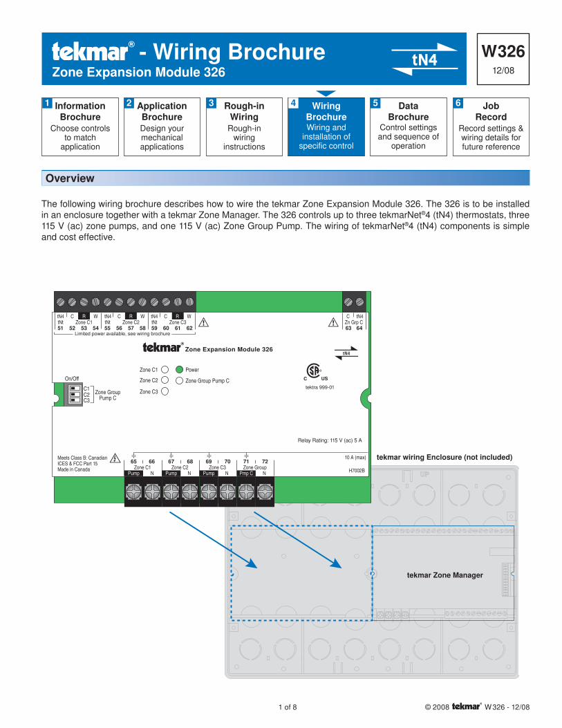
W 326 12/08Zone Expansion Module 326
- Wiring Brochure
1 of 8 © 2008 W 326 - 12/08
N NZone C1 Zone C2
65 66 67 68
Pump Pump
tN4
Meets Class B: CanadianICES & FCC Part 15Made in Canada
10 A (max)
Zone Expansion Module 326
tektra 999-01
Relay Rating: 115 V (ac) 5 A
NZone C3
69 70
Pump NZone Group71 72
Pmp C
Power
Zone Group Pump C
Zone C1
Zone C2
Zone C3
51 52 53 54 55 56 57 58 59 60 61 62
C CW WR RtN4 tN4 C WRtN4tNt Zone C1 tNt Zone C2 tNt Zone C3
63 64
C tN4Zn Grp C
C1C2
On/Off
Zone GroupPump CC3
Limited power available, see wiring brochure
H7002B
Information Brochure
Choose controlsto match
application
1 Application BrochureDesign your mechanical applications
2 Rough-inWiring
Rough-inwiring
instructions
3 WiringBrochureWiring and
installation of specific control
4 JobRecord
Record settings & wiring details for future reference
6DataBrochure
Control settings and sequence of
operation
5
Overview
tekmar wiring Enclosure (not included)
tekmar Zone Manager
The following wiring brochure describes how to wire the tekmar Zone Expansion Module 326. The 326 is to be installed in an enclosure together with a tekmar Zone Manager. The 326 controls up to three tekmarNet®4 (tN4) thermostats, three 115 V (ac) zone pumps, and one 115 V (ac) Zone Group Pump. The wiring of tekmarNet®4 (tN4) components is simple and cost effective.
© 2008 W 326 - 12/08 2 of 8
Table of Contents
Wiring Symbols & Definitions ........................................2
Module Installation .........................................................3
Electrical Drawings ......................................................4-5
Wiring the Control .......................................................6-7
Troubleshooting Instructions ..........................................8
Technical Data .............................................................. 12
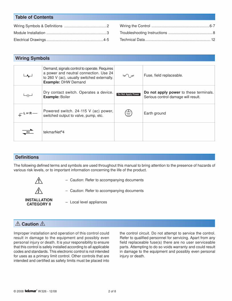
Defi nitions
The following defined terms and symbols are used throughout this manual to bring attention to the presence of hazards of various risk levels, or to important information concerning the life of the product.
– Caution: Refer to accompanying documents
– Caution: Refer to accompanying documents
INSTALLATIONCATEGORY II – Local level appliances
Improper installation and operation of this control could result in damage to the equipment and possibly even personal injury or death. It is your responsibility to ensure that this control is safely installed according to all applicable codes and standards. This electronic control is not intended for uses as a primary limit control. Other controls that are intended and certified as safety limits must be placed into
the control circuit. Do not attempt to service the control. Refer to qualified personnel for servicing. Apart from any field replaceable fuse(s) there are no user serviceable parts. Attempting to do so voids warranty and could result in damage to the equipment and possibly even personal injury or death.
Wiring Symbols
Demand, signals control to operate. Requires a power and neutral connection. Use 24 to 260 V (ac), usually switched externally.Example: DHW Demand
Fuse, field replaceable.
Dry contact switch. Operates a device.Example: Boiler
Do not apply power to these terminals. Serious control damage will result.
Powered switch. 24-115 V (ac) power, switched output to valve, pump, etc. Earth ground
tekmarNet®4
Caution
3 of 8 © 2008 W 326 - 12/08
Electrical Drawings
Module Installation
The electrical drawing examples on the following pages show the 326 in common applications. Choose the drawing that most accurately depicts the components in your system and use that drawing as a guide to aid in wiring your system.
These are only concept drawings, not engineered drawings. They are not intended to describe a complete system nor any particular system. It is up to the system designer to
determine the necessary components for and configuration of the particular system being designed including additional equipment isolation relays (for loads greater than the controls specified output ratings) and any safety devices which in the judgement of the designer are appropriate in order to properly size, configure and design that system and to ensure compliance with building and safety code requirements.
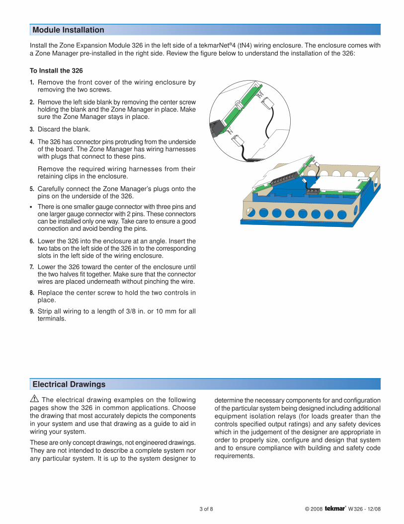
Install the Zone Expansion Module 326 in the left side of a tekmarNet®4 (tN4) wiring enclosure. The enclosure comes with a Zone Manager pre-installed in the right side. Review the figure below to understand the installation of the 326:
To Install the 326
1. Remove the front cover of the wiring enclosure by removing the two screws.
2. Remove the left side blank by removing the center screw holding the blank and the Zone Manager in place. Make sure the Zone Manager stays in place.
3. Discard the blank.
4. The 326 has connector pins protruding from the underside of the board. The Zone Manager has wiring harnesses with plugs that connect to these pins.
Remove the required wiring harnesses from their retaining clips in the enclosure.
5. Carefully connect the Zone Manager’s plugs onto the pins on the underside of the 326.
• • There is one smaller gauge connector with three pins and one larger gauge connector with 2 pins. These connectors can be installed only one way. Take care to ensure a good connection and avoid bending the pins.
6. Lower the 326 into the enclosure at an angle. Insert the two tabs on the left side of the 326 in to the corresponding slots in the left side of the wiring enclosure.
7. Lower the 326 toward the center of the enclosure until the two halves fit together. Make sure that the connector wires are placed underneath without pinching the wire.
8. Replace the center screw to hold the two controls in place.
9. Strip all wiring to a length of 3/8 in. or 10 mm for all terminals.
© 2008 W 326 - 12/08 4 of 8
Refer to Job Record for Maximum Allowable Loads
Connectionsfrom ZoneManager
24 V (ac) R & C
115 V (ac) L & N
To ground
To ground
Pump Pump Pump Pump
C tN4
tN4 C R Rh1 W1
tN4Thermostat
tN4 C R Rh1 W1
tN4Thermostat
tN4 C R Rh1 W1
tN4Thermostat
ExternaltN4 C
Connection
SeeD 326
N NZone C1 Zone C2
65 66 67 68
Pump Pump
tN4
Meets Class B: CanadianICES & FCC Part 15Made in Canada
10 A (max)
Zone Expansion Module 326
tektra 999-01
Relay Rating: 115 V (ac) 5 A
NZone C3
69 70
Pump NZone Group71 72
Pmp C
Power
Zone Group Pump C
Zone C1
Zone C2
Zone C3
51 52 53 54 55 56 57 58 59 60 61 62
C CW WR RtN4 tN4 C WRtN4tNt Zone C1 tNt Zone C2 tNt Zone C3
63 64
C tN4Zn Grp C
C1C2
On/Off
Zone GroupPump CC3
Limited power available, see wiring brochure
H7002B
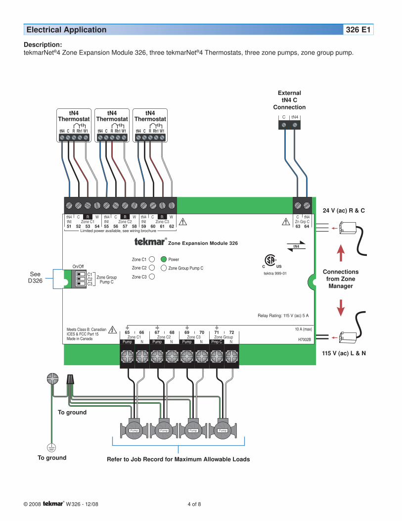
Electrical Application 326 E1
Description:tekmarNet®4 Zone Expansion Module 326, three tekmarNet®4 Thermostats, three zone pumps, zone group pump.
5 of 8 © 2008 W 326 - 12/08
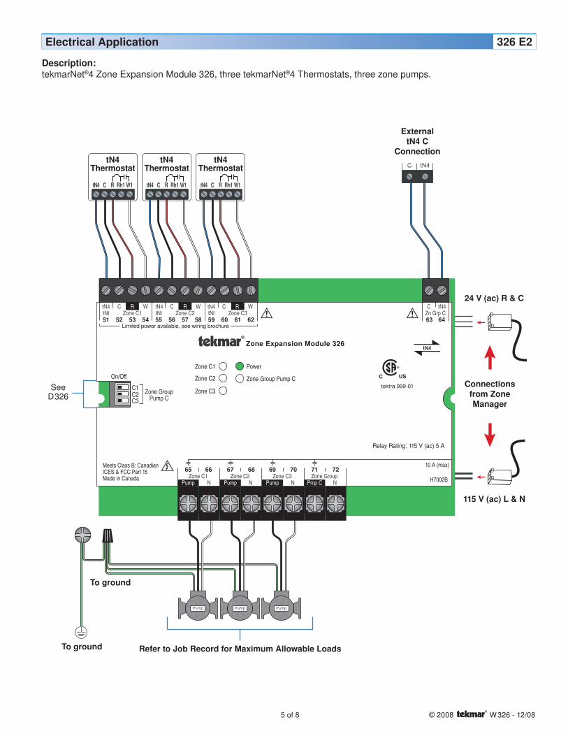
Electrical Application 326 E2
Refer to Job Record for Maximum Allowable Loads
Connectionsfrom ZoneManager
24 V (ac) R & C
115 V (ac) L & N
To ground
To ground
Pump Pump Pump
ExternaltN4 C
ConnectionC tN4
tN4 C R Rh1 W1
tN4Thermostat
tN4 C R Rh1 W1
tN4Thermostat
tN4 C R Rh1 W1
tN4Thermostat
SeeD 326
N NZone C1 Zone C2
65 66 67 68
Pump Pump
tN4
Meets Class B: CanadianICES & FCC Part 15Made in Canada
10 A (max)
Zone Expansion Module 326
tektra 999-01
Relay Rating: 115 V (ac) 5 A
NZone C3
69 70
Pump NZone Group71 72
Pmp C
Power
Zone Group Pump C
Zone C1
Zone C2
Zone C3
51 52 53 54 55 56 57 58 59 60 61 62
C CW WR RtN4 tN4 C WRtN4tNt Zone C1 tNt Zone C2 tNt Zone C3
63 64
C tN4Zn Grp C
C1C2
On/Off
Zone GroupPump CC3
Limited power available, see wiring brochure
H7002B
Description:tekmarNet®4 Zone Expansion Module 326, three tekmarNet®4 Thermostats, three zone pumps.
© 2008 W 326 - 12/08 6 of 8
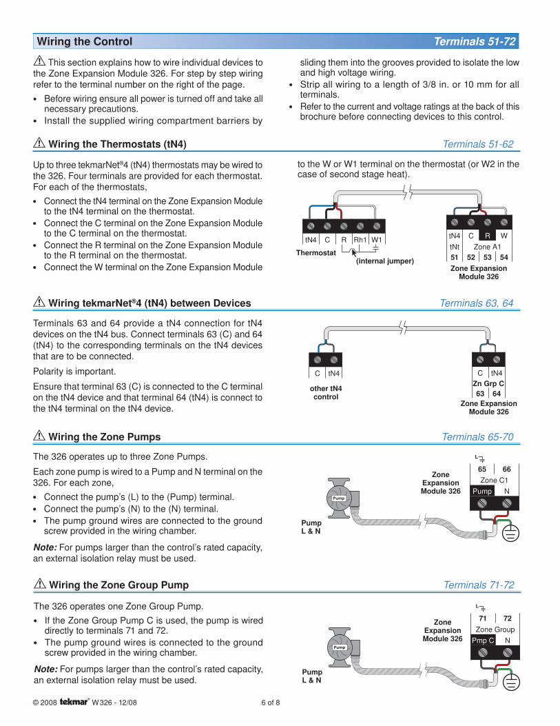
This section explains how to wire individual devices to the Zone Expansion Module 326. For step by step wiring refer to the terminal number on the right of the page. • • Before wiring ensure all power is turned off and take all
necessary precautions.• • Install the supplied wiring compartment barriers by
Terminals 63 and 64 provide a tN4 connection for tN4 devices on the tN4 bus. Connect terminals 63 (C) and 64 (tN4) to the corresponding terminals on the tN4 devices that are to be connected.
Polarity is important.
Ensure that terminal 63 (C) is connected to the C terminal on the tN4 device and that terminal 64 (tN4) is connect to the tN4 terminal on the tN4 device.
Wiring tekmarNet®4 (tN4) between Devices Terminals 63, 64
Up to three tekmarNet®4 (tN4) thermostats may be wired to the 326. Four terminals are provided for each thermostat. For each of the thermostats,• • Connect the tN4 terminal on the Zone Expansion Module
to the tN4 terminal on the thermostat.• • Connect the C terminal on the Zone Expansion Module
to the C terminal on the thermostat.• • Connect the R terminal on the Zone Expansion Module
to the R terminal on the thermostat.• • Connect the W terminal on the Zone Expansion Module
Wiring the Thermostats (tN4) Terminals 51-62
Wiring the Control Terminals 51-72
sliding them into the grooves provided to isolate the low and high voltage wiring.
• • Strip all wiring to a length of 3/8 in. or 10 mm for all terminals.
• • Refer to the current and voltage ratings at the back of this brochure before connecting devices to this control.
tN4 C R WtNt Zone A151 52 53 54
tN4 C R Rh1 W1
Zone ExpansionModule 326
(internal jumper)Thermostat
C tN4 C tN4Zn Grp C63 64
other tN4 control
Zone ExpansionModule 326
The 326 operates one Zone Group Pump. • • If the Zone Group Pump C is used, the pump is wired
directly to terminals 71 and 72.• • The pump ground wires is connected to the ground
screw provided in the wiring chamber.
Note: For pumps larger than the control’s rated capacity, an external isolation relay must be used.
Wiring the Zone Group Pump Terminals 71-72
Zone ExpansionModule 326
Pump
PumpL & N
The 326 operates up to three Zone Pumps.
Each zone pump is wired to a Pump and N terminal on the 326. For each zone,• • Connect the pump’s (L) to the (Pump) terminal.• • Connect the pump’s (N) to the (N) terminal.• • The pump ground wires are connected to the ground
screw provided in the wiring chamber.
Note: For pumps larger than the control’s rated capacity, an external isolation relay must be used.
Wiring the Zone Pumps Terminals 65-70
Zone ExpansionModule 326
Pump
PumpL & N
65 66Zone C1
Pump N
71 72Zone Group
Pmp C N
to the W or W1 terminal on the thermostat (or W2 in the case of second stage heat).
7 of 8 © 2008 W 326 - 12/08
General
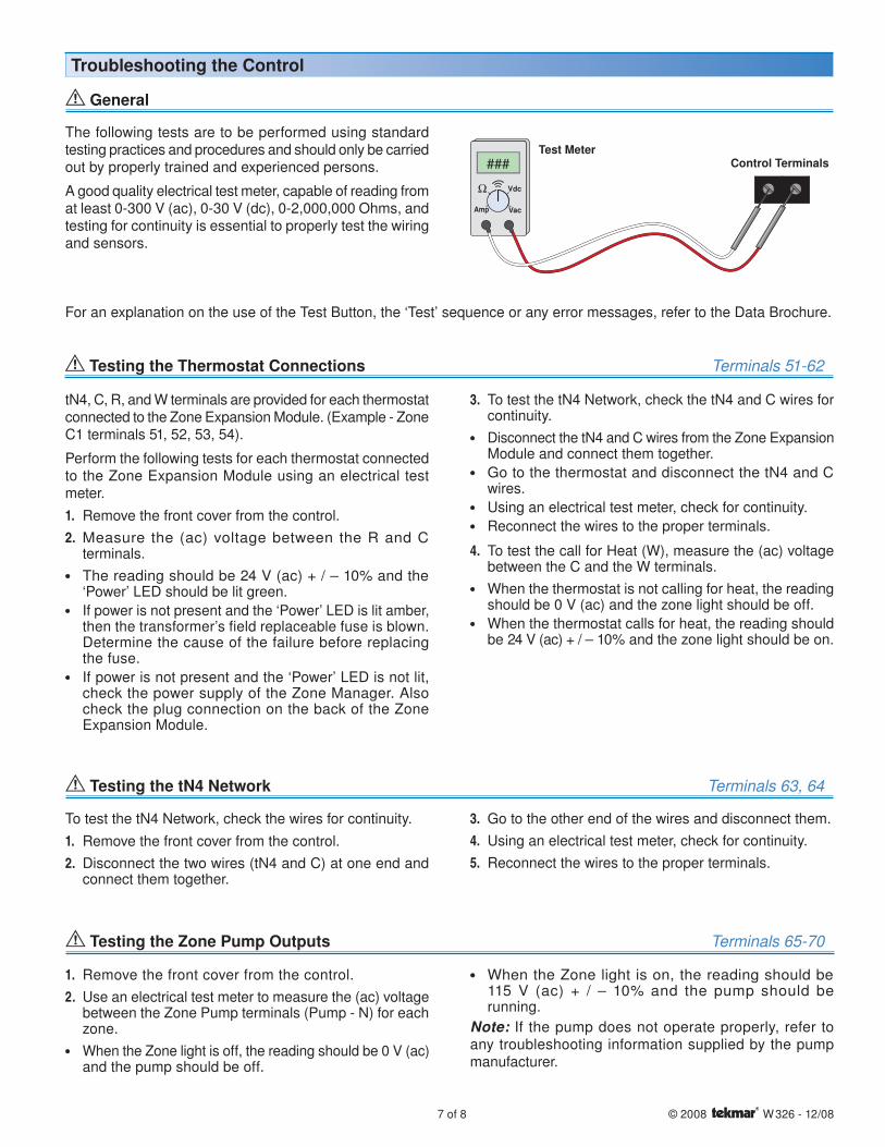
The following tests are to be performed using standard testing practices and procedures and should only be carried out by properly trained and experienced persons.
A good quality electrical test meter, capable of reading from at least 0-300 V (ac), 0-30 V (dc), 0-2,000,000 Ohms, and testing for continuity is essential to properly test the wiring and sensors.
Troubleshooting the Control
Test Meter### Control Terminals
Testing the tN4 Network Terminals 63, 64
To test the tN4 Network, check the wires for continuity.1. Remove the front cover from the control.2. Disconnect the two wires (tN4 and C) at one end and
connect them together.
3. Go to the other end of the wires and disconnect them.4. Using an electrical test meter, check for continuity.5. Reconnect the wires to the proper terminals.
Testing the Thermostat Connections Terminals 51-62
tN4, C, R, and W terminals are provided for each thermostat connected to the Zone Expansion Module. (Example - Zone C1 terminals 51, 52, 53, 54).
Perform the following tests for each thermostat connected to the Zone Expansion Module using an electrical test meter.1. Remove the front cover from the control.2. Measure the (ac) voltage between the R and C
terminals.• • The reading should be 24 V (ac) + / – 10% and the
‘Power’ LED should be lit green. • • If power is not present and the ‘Power’ LED is lit amber,
then the transformer’s field replaceable fuse is blown. Determine the cause of the failure before replacing the fuse.
• • If power is not present and the ‘Power’ LED is not lit, check the power supply of the Zone Manager. Also check the plug connection on the back of the Zone Expansion Module.
3. To test the tN4 Network, check the tN4 and C wires for continuity.
• • Disconnect the tN4 and C wires from the Zone Expansion Module and connect them together.
• • Go to the thermostat and disconnect the tN4 and C wires.
• • Using an electrical test meter, check for continuity.• • Reconnect the wires to the proper terminals.
4. To test the call for Heat (W), measure the (ac) voltage between the C and the W terminals.
• • When the thermostat is not calling for heat, the reading should be 0 V (ac) and the zone light should be off.
• • When the thermostat calls for heat, the reading should be 24 V (ac) + / – 10% and the zone light should be on.
For an explanation on the use of the Test Button, the ‘Test’ sequence or any error messages, refer to the Data Brochure.
Testing the Zone Pump Outputs Terminals 65-70
1. Remove the front cover from the control.2. Use an electrical test meter to measure the (ac) voltage
between the Zone Pump terminals (Pump - N) for each zone.
• • When the Zone light is off, the reading should be 0 V (ac) and the pump should be off.
• • When the Zone light is on, the reading should be115 V (ac) + / – 10% and the pump should berunning.
Note: If the pump does not operate properly, refer to any troubleshooting information supplied by the pump manufacturer.
tekmar Control Systems Ltd., Canadatekmar Control Systems, Inc., U.S.A.Head Office: 5100 Silver Star RoadVernon, B.C. Canada V1B 3K4(250) 545-7749 Fax. (250) 545-0650Web Site: www.tekmarcontrols.com
Product design, software and literature are Copyright © 2008 by:tekmar Control Systems Ltd. and tekmar Control Systems, Inc. 8 of 8 All specifications are subject to change without notice.
Printed in Canada. W 326 - 12/08.
The installer must ensure that this control and its wiring are isolated and/or shielded from strong sources of electromagnetic noise. Conversely, this Class B digital apparatus complies with Part 15 of the FCC Rules and meets all requirements of the Canadian Interference-Causing Equipment Regulations. However, if this control does cause harmful interference to radio or television reception, which is determined by turning the control off and on, the user is encouraged to try to correct the interference by re-orientating or relocating the receiving antenna, relocating the receiver with respect to this control, and/or connecting the control to a different circuit from that to which the receiver is connected.
Cet appareil numérique de la classe B respecte toutes les exigences du Règlement sur le matériel brouilleur du Canada.
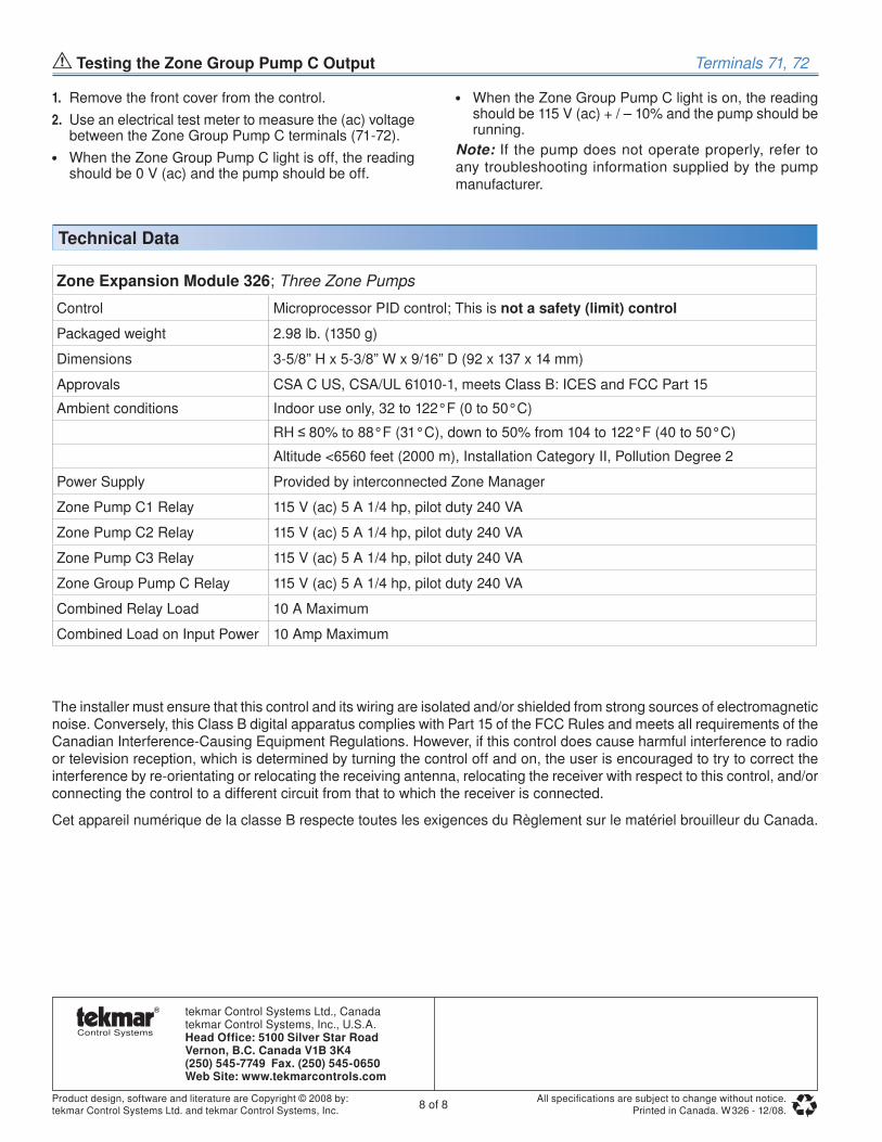
Zone Expansion Module 326; Three Zone Pumps
Control Microprocessor PID control; This is not a safety (limit) control
Packaged weight 2.98 lb. (1350 g)
Dimensions 3-5/8” H x 5-3/8” W x 9/16” D (92 x 137 x 14 mm)
Approvals CSA C US, CSA/UL 61010-1, meets Class B: ICES and FCC Part 15
Ambient conditions Indoor use only, 32 to 122°F (0 to 50°C)
RH 80% to 88°F (31°C), down to 50% from 104 to 122°F (40 to 50°C)
Altitude <6560 feet (2000 m), Installation Category II, Pollution Degree 2
Power Supply Provided by interconnected Zone Manager
Zone Pump C1 Relay 115 V (ac) 5 A 1/4 hp, pilot duty 240 VA
Zone Pump C2 Relay 115 V (ac) 5 A 1/4 hp, pilot duty 240 VA
Zone Pump C3 Relay 115 V (ac) 5 A 1/4 hp, pilot duty 240 VA
Zone Group Pump C Relay 115 V (ac) 5 A 1/4 hp, pilot duty 240 VA
Combined Relay Load 10 A Maximum
Combined Load on Input Power 10 Amp Maximum
Technical Data
Testing the Zone Group Pump C Output Terminals 71, 72
1. Remove the front cover from the control.2. Use an electrical test meter to measure the (ac) voltage
between the Zone Group Pump C terminals (71-72).• • When the Zone Group Pump C light is off, the reading
should be 0 V (ac) and the pump should be off.
• • When the Zone Group Pump C light is on, the reading should be 115 V (ac) + / – 10% and the pump should be running.
Note: If the pump does not operate properly, refer to any troubleshooting information supplied by the pump manufacturer.