Embed Size (px)
Citation preview
5427 hollister avenue, santa barbara, ca 93111tel 805.964.9610 fax 805.964.9749
www.seymourduncan.com
Wiring Diagram for
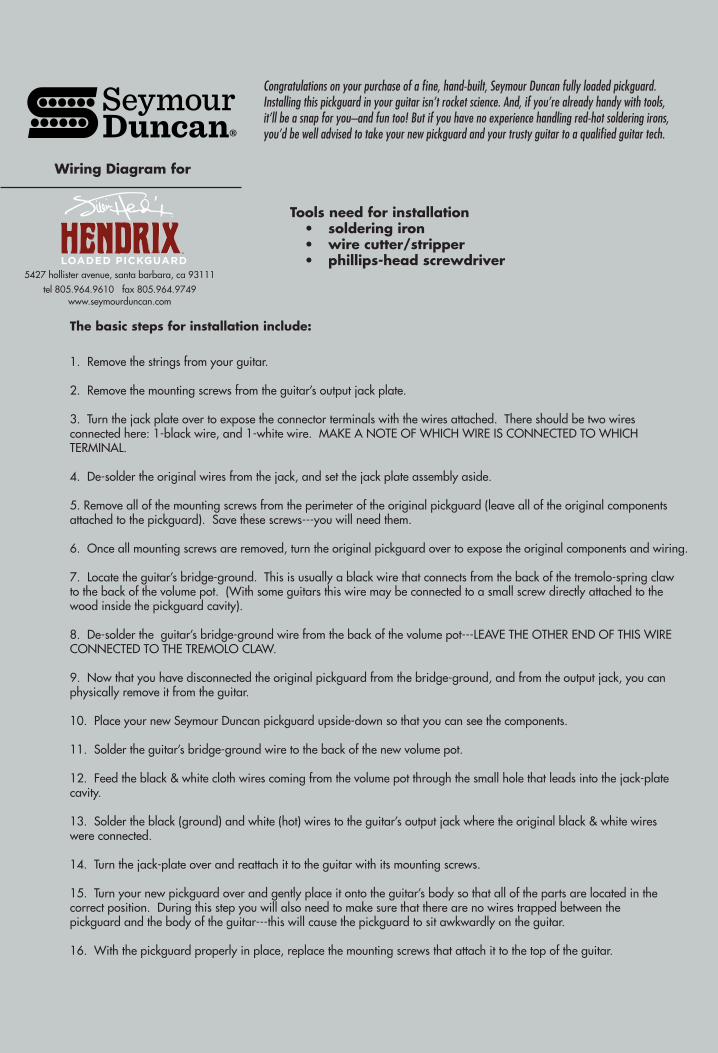
The basic steps for installation include:
1. Remove the strings from your guitar.
2. Remove the mounting screws from the guitar’s output jack plate.
3. Turn the jack plate over to expose the connector terminals with the wires attached. There should be two wires connected here: 1-black wire, and 1-white wire. MAKE A NOTE OF WHICH WIRE IS CONNECTED TO WHICH TERMINAL.
4. De-solder the original wires from the jack, and set the jack plate assembly aside.
5. Remove all of the mounting screws from the perimeter of the original pickguard (leave all of the original components attached to the pickguard). Save these screws---you will need them.
6. Once all mounting screws are removed, turn the original pickguard over to expose the original components and wiring.
7. Locate the guitar’s bridge-ground. This is usually a black wire that connects from the back of the tremolo-spring claw to the back of the volume pot. (With some guitars this wire may be connected to a small screw directly attached to the wood inside the pickguard cavity).
8. De-solder the guitar’s bridge-ground wire from the back of the volume pot---LEAVE THE OTHER END OF THIS WIRE CONNECTED TO THE TREMOLO CLAW.
9. Now that you have disconnected the original pickguard from the bridge-ground, and from the output jack, you can physically remove it from the guitar.
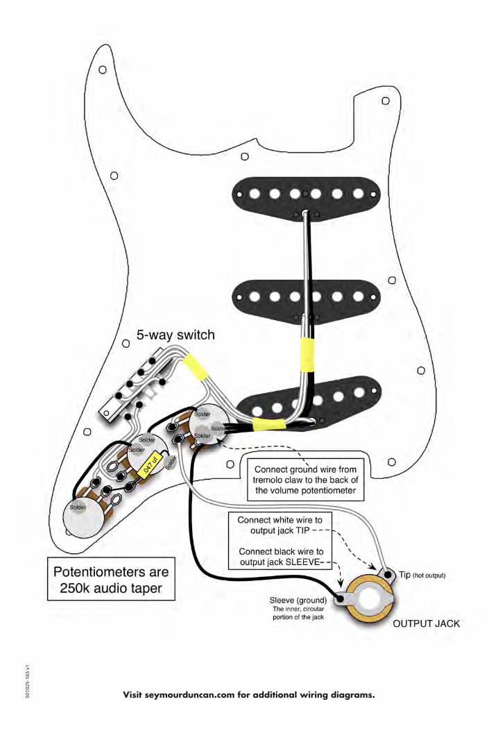
10. Place your new Seymour Duncan pickguard upside-down so that you can see the components.
11. Solder the guitar’s bridge-ground wire to the back of the new volume pot.
12. Feed the black & white cloth wires coming from the volume pot through the small hole that leads into the jack-plate cavity.
13. Solder the black (ground) and white (hot) wires to the guitar’s output jack where the original black & white wires were connected.
14. Turn the jack-plate over and reattach it to the guitar with its mounting screws.
15. Turn your new pickguard over and gently place it onto the guitar’s body so that all of the parts are located in the correct position. During this step you will also need to make sure that there are no wires trapped between the pickguard and the body of the guitar---this will cause the pickguard to sit awkwardly on the guitar.
16. With the pickguard properly in place, replace the mounting screws that attach it to the top of the guitar.
Congratulations on your purchase of a fine, hand-built, Seymour Duncan fully loaded pickguard. Installing this pickguard in your guitar isn’t rocket science. And, if you’re already handy with tools, it’ll be a snap for you–and fun too! But if you have no experience handling red-hot soldering irons, you’d be well advised to take your new pickguard and your trusty guitar to a qualified guitar tech.
Tools need for installation• soldering iron• wire cutter/stripper• phillips-head screwdriver
We’re not just pickups anymore. Seymour Duncan also makes boutique quality stomp boxes for the working musician.
Visit seymourduncan.com for additional wiring diagrams.
Additional Wiring Options50
1025
-165
v1


![6 . Wiring Diagram Legacy/Service Manual/1996 LEGACY RH… · 6-3 [D601] WIRING DIAGRAM 6 . Wiring Diagram 6 . Wiring Diagram Battery current 1 . POWER SUPPLY ROUTING Current from](https://img.pdfslide.net/doc/110x75/6058f70ca8a7ee39513c5dc6/6-wiring-legacyservice-manual1996-legacy-rh-6-3-d601-wiring-diagram-6-.jpg)
![6. Wiring Diagram - weidefamily.net coil Transmission control module ... WIRING DIAGRAM 6. Wiring Diagram. MEMO: 21 WIRING DIAGRAM ... 76 6-3 [D6R2] WIRING DIAGRAM 6](https://img.pdfslide.net/doc/110x75/5aa0cc3b7f8b9a62178ea5e7/6-wiring-diagram-coil-transmission-control-module-wiring-diagram-6-wiring.jpg)