Embed Size (px)
Citation preview
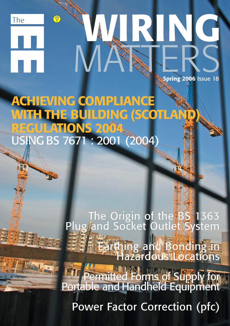
WIRINGMATTERS
Spring 2006 Issue 18
The Origin of the BS 1363 Plug and Socket Outlet System
Earthing and Bonding in Hazardous Locations
Permitted Forms of Supply for Portable and Handheld Equipment
Power Factor Correction (pfc)
The Origin of the BS 1363 Plug and Socket Outlet System
Earthing and Bonding in Hazardous Locations
Permitted Forms of Supply for Portable and Handheld Equipment
Power Factor Correction (pfc)
ACHIEVING COMPLIANCEWITH THE BUILDING (SCOTLAND)REGULATIONS 2004USING BS 7671 : 2001 (2004)
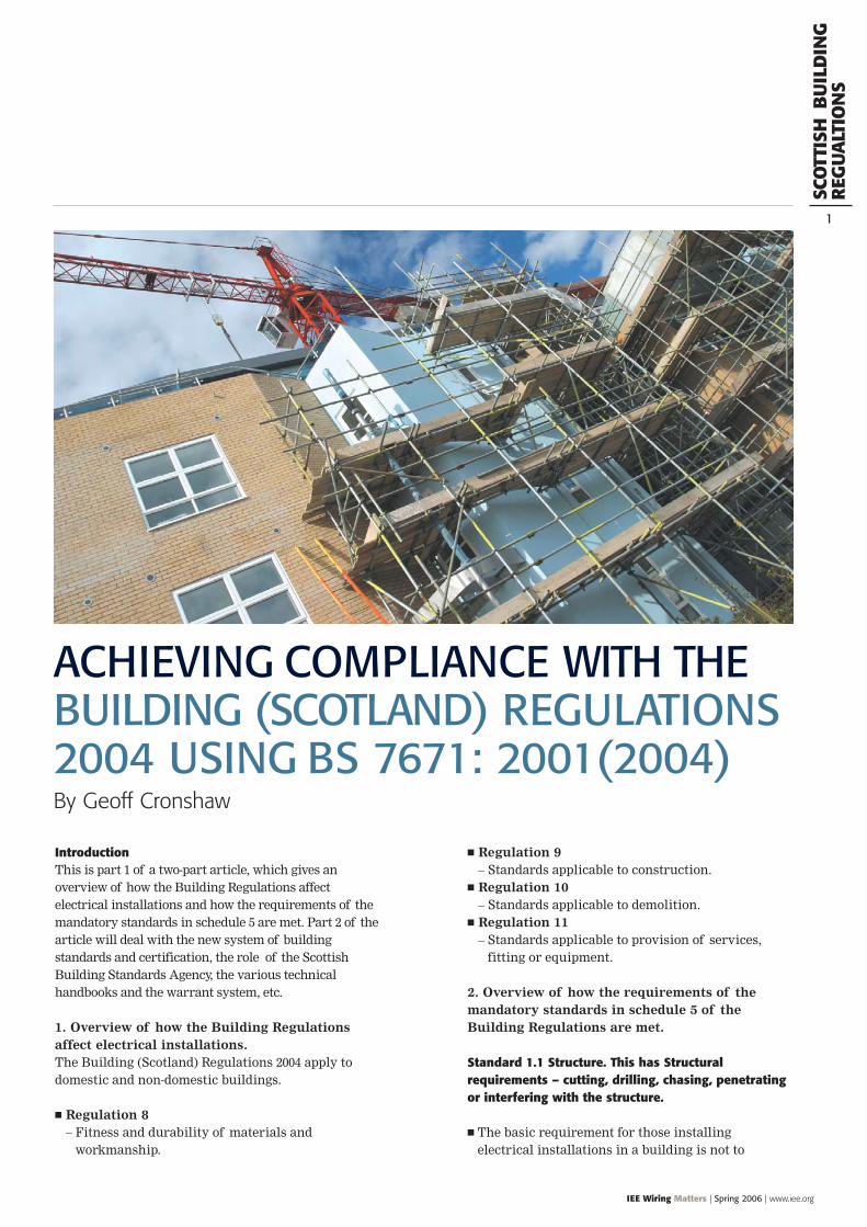
IntroductionThis is part 1 of a two-part article, which gives anoverview of how the Building Regulations affectelectrical installations and how the requirements of themandatory standards in schedule 5 are met. Part 2 of thearticle will deal with the new system of buildingstandards and certification, the role of the ScottishBuilding Standards Agency, the various technicalhandbooks and the warrant system, etc.
1. Overview of how the Building Regulationsaffect electrical installations.The Building (Scotland) Regulations 2004 apply todomestic and non-domestic buildings.
Regulation 8– Fitness and durability of materials and
workmanship.
IEE Wiring Matters | Spring 2006 | www.iee.org
Regulation 9 – Standards applicable to construction.
Regulation 10 – Standards applicable to demolition.
Regulation 11 – Standards applicable to provision of services,
fitting or equipment.
2. Overview of how the requirements of themandatory standards in schedule 5 of theBuilding Regulations are met.
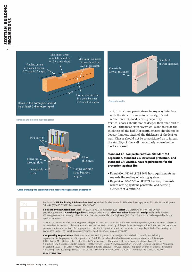
Standard 1.1 Structure. This has Structuralrequirements – cutting, drilling, chasing, penetratingor interfering with the structure.
The basic requirement for those installingelectrical installations in a building is not to
ACHIEVING COMPLIANCE WITH THEBUILDING (SCOTLAND) REGULATIONS2004 USING BS 7671: 2001(2004)
SCO
TTIS
HB
UIL
DIN
GR
EGU
ALT
ION
S
1
By Geoff Cronshaw
SCO
TTIS
HB
UIL
DIN
GR
EGU
ALT
ION
S
2
IEE Wiring Matters | Spring 2006 | www.iee.org
Published by IEE Publishing & Information Services Michael Faraday House, Six Hills Way, Stevenage, Herts, SG1 2AY, United KingdomTel: +44 (0)1438 313311 Fax: +44 (0)1438 313465
Sales and Project Coordinator L Hall +44 (0)1438 767351 [email protected] | Editor G D Cronshaw +44 (0)1438 [email protected] | Contributing Editors J Ware, M Coles, J Elliott | Chief Sub Editor Jim Hannah | Design Sable Media SolutionsIEE Wiring Matters is a quarterly publication from the Institution of Electrical Engineers (IEE). The IEE is not as a body responsible for theopinions expressed.
©2006: The Institution of Electrical Engineers. All rights reserved. No part of this publication may be reproduced, stored in a retrieval system,or transmitted in any form or by any means without the permission in writing of the publisher. Copying of articles is not permitted except forpersonal and internal use. Multiple copying of the content of this publication without permission is always illegal. Web-offset printing byWyndeham Heron, The Bentall Complex, Colchester Road, Heybridge, Maldon, Essex, UK
Co-operating Organisations The Institution of Electrical Engineers acknowledges the contribution made by the followingorganisations in the preparation of this publication: British Electrotechnical & Allied Manufacturers Association Ltd – R Lewington,P D Galbraith, M H Mullins | Office of the Deputy Prime Minister – I Drummond | Electrical Contractors Association – D Locke, S Burchell | City & Guilds of London Institute – H R Lovegrove | Energy Networks Association –D J Start | Electrical Contractors Association of Scotland SELECT – D Millar, N McGuiness | Health & Safety Executive – N Gove | National Inspection Council for Electrical InstallationContracting | ERA Technology Limited – M Coates | British Cables Association – C Reed | Scottish Building Standards Agency
ISSN 1749-978-X
cut, drill, chase, penetrate or in any way interferewith the structure so as to cause significantreduction in its load bearing capability.
Vertical chases should not be deeper than one-third ofthe wall thickness or in cavity walls one-third of thethickness of the leaf. Horizontal chases should not bedeeper than one-sixth of the thickness of the leaf orwall. Chases should not be so positioned as to impairthe stability of the wall particularly where hollowblocks are used.
Standard 2.1 Compartmentation, Standard 2.2Separation, Standard 2.3 Structural protection, andStandard 2.4 Cavities, have requirements for theprotection against fire.
Regulation 527-02 of BS 7671 has requirements asregards the sealing of wiring system.
Regulation 522-12-03 of BS7671 has requirementswhere wiring systems penetrate load bearingelements of a building.Cable trunking fire sealed where it passes through a floor penetration
Chases in walls
Notches and holes in wooden joists
SCO
TTIS
HB
UIL
DIN
GR
EGU
ALT
ION
S
4
IEE Wiring Matters | Spring 2006 | www.iee.org
Standard 2.5 Internal linings, has requirements forprotection against fire spread on internal linings.
Every building must be designed and constructedin such a way that in the event of an outbreak offire within the building, the development of fireand smoke from the surfaces of walls and ceilingswithin the area of origin is inhibited.
This clause has requirements regardingthermoplastic materials in light fitting diffusers.
Where light fitting diffusers form an integral part ofa fire-resisting ceiling which has been satisfactorilytested, the amount of thermoplastic material isunlimited.
Where light fittings with thermoplastic diffusers donot form an integral part of the ceiling, the amountof thermoplastic material is unlimited provided thelighting diffuser is designed to fall out of itsmounting when softened by heat.
Standard 2.10 Escape lighting – Every building mustbe designed and constructed in such a way that inthe event of an outbreak of fire within the building,illumination is provided to assist in escape.
The emergency lighting should be installed inaccordance with BS 5266.
Standard 2.11 Communication, has requirements foralerting occupants in the event of an outbreak of firewithin the building.
BS 5839 is the British Standard to refer to. Clause 2.14 has requirements to provide facilities
to assist fire-fighting or rescue operations. Thisincludes requirements for smoke extract equipment etc.
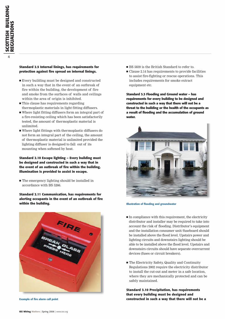
Standard 3.3 Flooding and Ground water – hasrequirements for every building to be designed andconstructed in such a way that there will not be athreat to the building or the health of the occupants asa result of flooding and the accumulation of groundwater.
In compliance with this requirement, the electricitydistributor and installer may be required to take intoaccount the risk of flooding. Distributor’s equipmentand the installation consumer unit/fuseboard shouldbe installed above the flood level. Upstairs power andlighting circuits and downstairs lighting should beable to be installed above the flood level. Upstairs anddownstairs circuits should have separate overcurrentdevices (fuses or circuit breakers).
The Electricity Safety, Quality and ContinuityRegulations 2002 require the electricity distributorto install the cut-out and meter in a safe location,where they are mechanically protected and can besafely maintained.
Standard 3.10 Precipitation, has requirementsthat every building must be designed andconstructed in such a way that there will not be aExample of fire alarm call point
Illustration of flooding and groundwater
SCO
TTIS
HB
UIL
DIN
GR
EGU
ALT
ION
S
IEE Wiring Matters | Spring 2006 | www.iee.org
5
threat to the building or the health of the occupantsas a result of moisture from precipitationpenetrating to the inner face of the building.
Ensure that holes for electrical services entering abuilding are sealed.
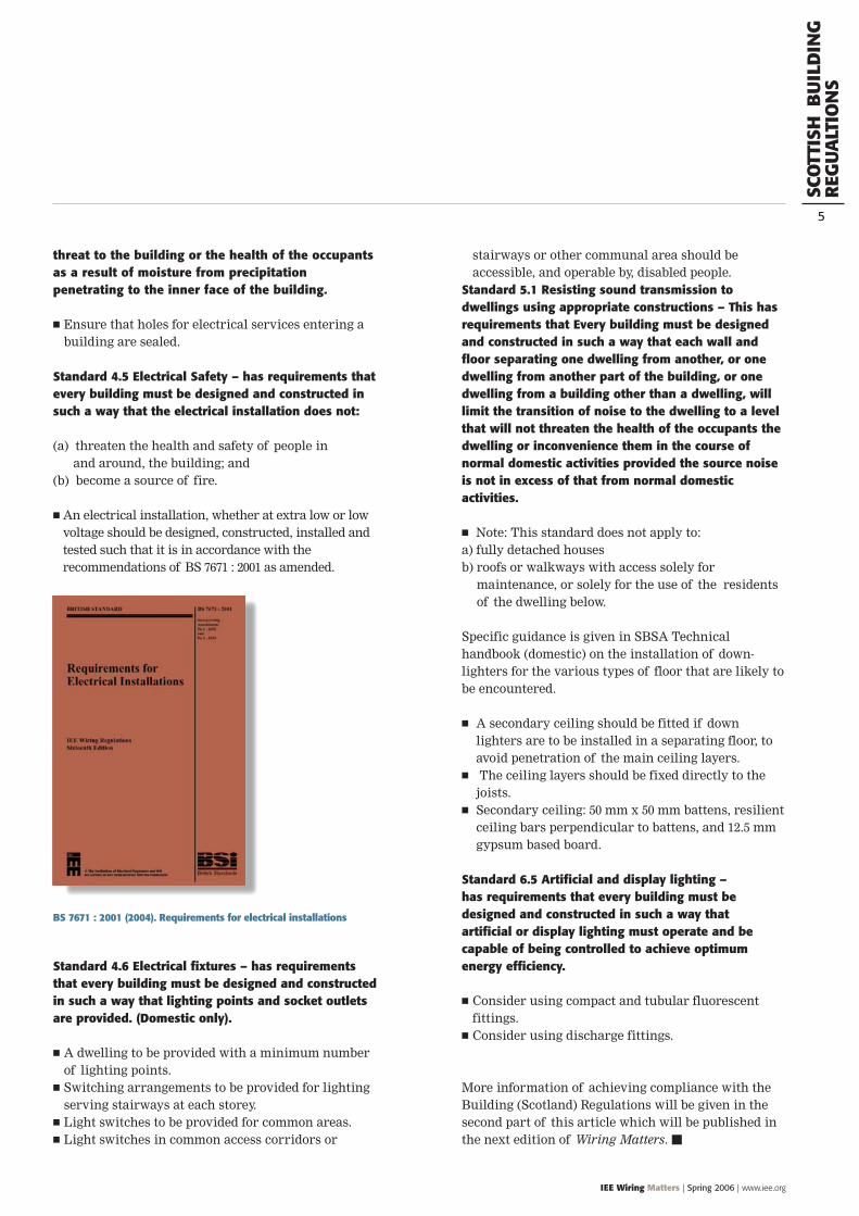
Standard 4.5 Electrical Safety – has requirements thatevery building must be designed and constructed insuch a way that the electrical installation does not:
(a) threaten the health and safety of people inand around, the building; and
(b) become a source of fire.
An electrical installation, whether at extra low or lowvoltage should be designed, constructed, installed andtested such that it is in accordance with therecommendations of BS 7671 : 2001 as amended.
Standard 4.6 Electrical fixtures – has requirementsthat every building must be designed and constructedin such a way that lighting points and socket outletsare provided. (Domestic only).
A dwelling to be provided with a minimum numberof lighting points.
Switching arrangements to be provided for lightingserving stairways at each storey.
Light switches to be provided for common areas. Light switches in common access corridors or
stairways or other communal area should beaccessible, and operable by, disabled people.
Standard 5.1 Resisting sound transmission todwellings using appropriate constructions – This hasrequirements that Every building must be designedand constructed in such a way that each wall andfloor separating one dwelling from another, or onedwelling from another part of the building, or onedwelling from a building other than a dwelling, willlimit the transition of noise to the dwelling to a levelthat will not threaten the health of the occupants thedwelling or inconvenience them in the course ofnormal domestic activities provided the source noiseis not in excess of that from normal domesticactivities.
Note: This standard does not apply to:a) fully detached housesb) roofs or walkways with access solely for
maintenance, or solely for the use of the residentsof the dwelling below.
Specific guidance is given in SBSA Technicalhandbook (domestic) on the installation of down-lighters for the various types of floor that are likely tobe encountered.
A secondary ceiling should be fitted if downlighters are to be installed in a separating floor, toavoid penetration of the main ceiling layers.
The ceiling layers should be fixed directly to thejoists.
Secondary ceiling: 50 mm x 50 mm battens, resilientceiling bars perpendicular to battens, and 12.5 mmgypsum based board.
Standard 6.5 Artificial and display lighting – has requirements that every building must bedesigned and constructed in such a way that artificial or display lighting must operate and becapable of being controlled to achieve optimumenergy efficiency.
Consider using compact and tubular fluorescentfittings.
Consider using discharge fittings.
More information of achieving compliance with theBuilding (Scotland) Regulations will be given in thesecond part of this article which will be published inthe next edition of Wiring Matters.
BS 7671 : 2001 (2004). Requirements for electrical installations
BS
1363
PLU
G A
ND
SOC
KET
-OU
TLET
6
IEE Wiring Matters | Spring 2006 | www.iee.org
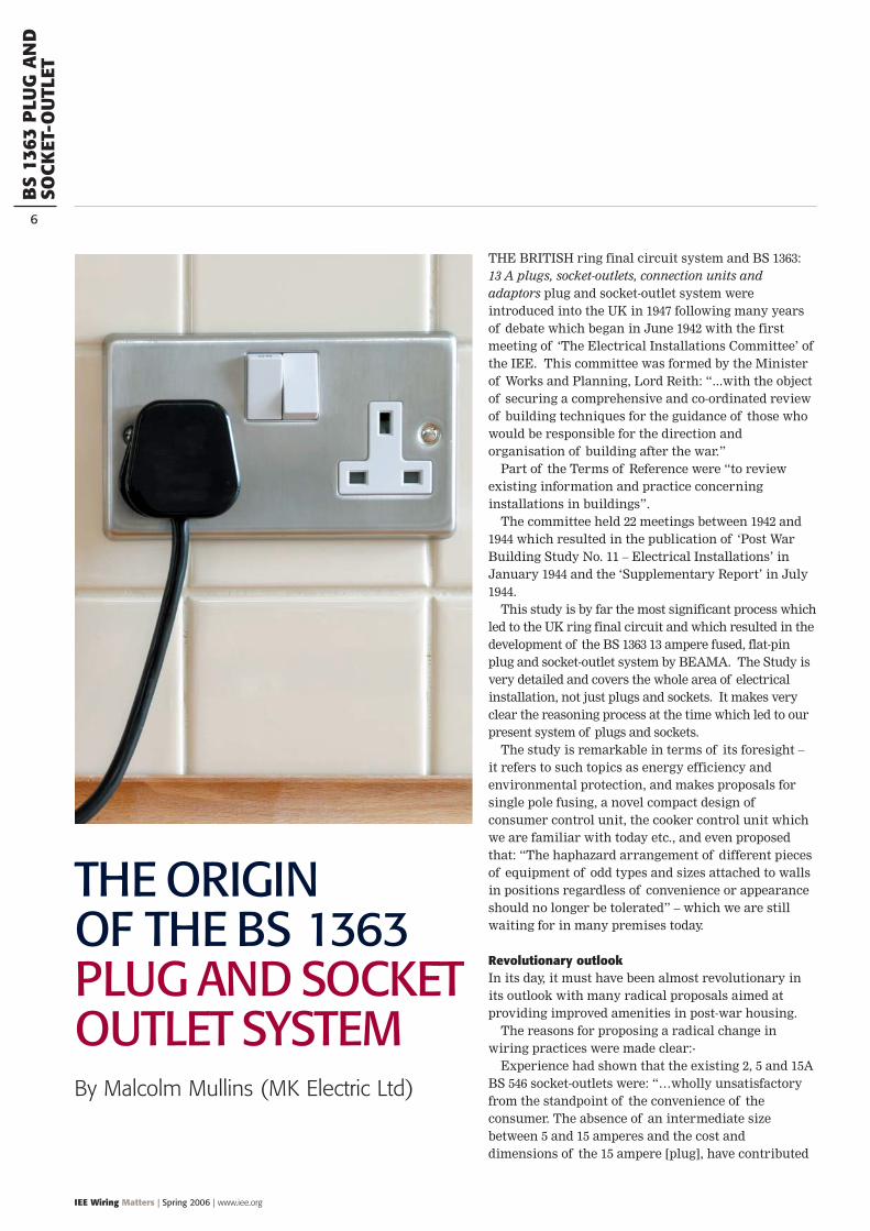
THE BRITISH ring final circuit system and BS 1363:13 A plugs, socket-outlets, connection units andadaptors plug and socket-outlet system wereintroduced into the UK in 1947 following many yearsof debate which began in June 1942 with the firstmeeting of ‘The Electrical Installations Committee’ ofthe IEE. This committee was formed by the Ministerof Works and Planning, Lord Reith: “...with the objectof securing a comprehensive and co-ordinated reviewof building techniques for the guidance of those whowould be responsible for the direction andorganisation of building after the war.”
Part of the Terms of Reference were “to reviewexisting information and practice concerninginstallations in buildings”.
The committee held 22 meetings between 1942 and1944 which resulted in the publication of ‘Post WarBuilding Study No. 11 – Electrical Installations’ inJanuary 1944 and the ‘Supplementary Report’ in July1944.
This study is by far the most significant process whichled to the UK ring final circuit and which resulted in thedevelopment of the BS 1363 13 ampere fused, flat-pinplug and socket-outlet system by BEAMA. The Study isvery detailed and covers the whole area of electricalinstallation, not just plugs and sockets. It makes veryclear the reasoning process at the time which led to ourpresent system of plugs and sockets.
The study is remarkable in terms of its foresight – it refers to such topics as energy efficiency andenvironmental protection, and makes proposals forsingle pole fusing, a novel compact design ofconsumer control unit, the cooker control unit whichwe are familiar with today etc., and even proposedthat: “The haphazard arrangement of different piecesof equipment of odd types and sizes attached to wallsin positions regardless of convenience or appearanceshould no longer be tolerated” – which we are stillwaiting for in many premises today.
Revolutionary outlookIn its day, it must have been almost revolutionary inits outlook with many radical proposals aimed atproviding improved amenities in post-war housing.
The reasons for proposing a radical change inwiring practices were made clear:-
Experience had shown that the existing 2, 5 and 15ABS 546 socket-outlets were: “…wholly unsatisfactoryfrom the standpoint of the convenience of theconsumer. The absence of an intermediate sizebetween 5 and 15 amperes and the cost anddimensions of the 15 ampere [plug], have contributed
THE ORIGINOF THE BS 1363PLUG AND SOCKETOUTLET SYSTEMBy Malcolm Mullins (MK Electric Ltd)
BS
1363
PLU
G A
ND
SOC
KET
-OU
TLET
IEE Wiring Matters | Spring 2006 | www.iee.org
7
to the use of non-standard socket-outlets and plugs tofill a gap in which there is substantial demand.’” BS 546 is entitled: Specification. Two-pole and earthingpin plugs, socket-outlets and socket-outlet adaptors.
Improved safety was of course a major objective ofthis whole exercise. Particular reference was made tochildren and the need for shutters and to thereduction of the likelihood of damage by flush-mounting and by mounting well above floor-level.
Recognition of the rapid moves towards the use ofmore and more electrical appliances in the home withthe resulting need for a multitude of socket-outlets inpost-war housing which the ‘new’ ring-circuit couldprovide was a major factor. Even in 1944, there wasconcern over “...the rapidly increasing number of thesesmall consumption appliances...”.
The emphasis throughout this study has been theeconomical provision of many sockets-outlets as wellas the supply of heating loads. The Study states: “theinstallation should allow the occupier to useelectricity, if he so desires, for providing ‘topping up’heat. Bearing in mind the limited cubic capacity andthe load diversity of the small dwelling under review,it is considered that they could be adequately heatedelectrically using portable or inset electrical fires orconvectors up to 2 kW rating from the ring circuit.
“This [substantial demand] applies to the smallerclasses of dwellings in which 2 kW radiant electricfires are commonly used, and in which fires or otherappliances exceeding this rating are seldom requireddue to the limitations imposed by the size of the room.”
The ring final circuitIt was decided during this study that the alternative ofproviding a separate circuit fused at 15 amperes foreach principal room which would feed all socket-outlets in that room: “is attractive as compared withpre-war practices but is less flexible in installationthan the ring-circuit, provides less flexibility inloading and, except possibly in the smaller type ofhouse, is not so economical.”
It was realised that a post-war Britain wouldcontinue to suffer from a massive shortage of rawmaterials and it was estimated that the proposedchanges to the ring-circuit and single-pole fusingwould show a saving of approximately 25% comparedwith pre-war regulations. The opportunity to improveboth consumer safety and convenience due to theinterruption in new building during the war and themassive programme of building which would berequired after the war was recognised at an earlystage. Initially, a majority favoured a new British
Standard for a 10 A, fused, shuttered socket-outlet anda plug with round pins conforming to BS 546. Thefinal unanimous decision was for a 3 kW (230V; 13 A)socket-outlet with fused plugs.
BEAMA were invited to propose suitable designs orstandards which they accepted.
The following observation was made in the report:“The general benefit to be obtained from the widest useof a single standard is so great as to call for thesubordination of individual preference, or even ofcomparatively minor technical consideration, to thechoice of the alternative most likely to meet withgeneral acceptance.” This is just as valid today as longas safety is assured.
Much has been written about ring final circuits andBS 1363 accessories since the second world-war. Ofparticular interest is ‘Ministry of Works TechnicalNote No. 4’ published in 1957. This pamphlet begins inits opening paragraph: “Socket-outlets should providea safe and convenient means of plugging in portableappliances to the electric supply, but unfortunatelythey have long been regarded as an expensive luxuryand it is sometimes wrongly thought that economycan be achieved only by reducing their number.Nowadays, however, because of the increasing use ofdomestic electrical equipment, more socket-outletsthan ever before are needed.”
Later in the pamphlet the danger of too few socket-outlets is again highlighted where householders aretempted to use trailing sockets which becomeregarded as permanent wiring, but are susceptible todamage and present a serious fire and shock rise. Asregards to the ring-circuit and BS 1363 accessories,the pamphlet continues: “The ring circuit system ofwiring takes full advantage of domestic load diversitybecause one circuit serves an unlimited number ofstandard socket-outlets (BS 1363 type of 13 Amprating) which may be used at any time and added toafter if required. A large fuse at the meter end of theinstallation that has to be capable of carrying the fullload of current drawn from several socket-outlets atonce may not protect a flexible cord leading from anindividual socket. The way to ensure adequate andselective protection is to connect each flexible cord toa separately fused plug.”
The pamphlet highlights cost-savings between thepre-war system where a typical 3 bedroom urbanhome would require at least nine 15 amp fuseswhereas a ring-circuit system required one 30 ampfuse for the required number (15 in this case) ofsocket-outlets. Although modern radial or treecircuits can supply more than one socket-outlet, they
BS
1363
PLU
G A
ND
SOC
KET
-OU
TLET
8
IEE Wiring Matters | Spring 2006 | www.iee.org
would still require more overcurrent protectivedevices, a larger consumer unit, more cable and areusually more expensive to install.
The pamphlet emphasises that the ring circuitsystem required 30% less cable and can save about25% in the cost of the wiring of a house andconcludes: “There is no doubt that in moderndomestic premises that are to be adequately providedwith electric points, the cheapest and safest system isto use a ring final circuit.”
Modern wiring needs are obviously different to whatwas envisaged in 1944 but (apart from the even greaterincrease in small portable appliances originally seen as ajustification for ring final circuits) the main change hasbeen the increase in size (i.e. area) of installations whichutilise ring final circuits. The reasoning in 1944 centredon the tendency before the war for an increase in smalldomestic dwellings with an expectation that this wouldincrease after the war. The emphasis was on a newsystem for housing that would allow a multitude ofsocket-outlets without a corresponding need for manyfinal circuits. Remember that pre-war usual practicewas to supply a single socket from one fuse and to usedifferent size plugs and sockets (usually to BS 546) toensure that the maximum allowable current loading of
the flexible cable and appliance was not exceeded so as toprovide overload protection. Not until the 12th Edition ofthe Wiring Regulations did the UK accept the Continentalpractice of increased risks of damage in radial circuitsdue to overload and small over-currents due to the ratingof the overcurrent protective device being greater thanthe rating of the flex and appliances.
The Post-War Study could not have foreseen themassive increases in commercial wiring needs inoffices due to information technology. Thesophisticated wiring systems now available (e.g.perimeter trunking, underfloor powertrack systems)mean that large numbers of socket-outlets arerequired. Ring final circuits are often used in suchinstallations and a BSRIA report commissioned by the DTI in 1994 shows clearly that ring final circuitscost less to install than the equivalent radial circuits.
The British plug and socket and ring final circuitsystem has proven itself over many years. Itsdevelopment was due to the recognition of anopportunity seen by leaders during a time of war andmass destruction. A truly unique, innovative, worldclass system was developed by people of vision. Asystem that cannot be equalled in terms of safety,performance and convenience.
Above left:Study no 11
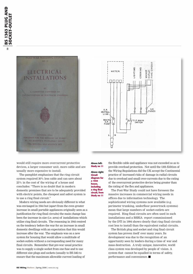
Above right:Circuitdiagram fora 1944house,including a ring finalcircuit, fromStudy no 11
HA
ZAD
OU
SLO
CATI
ON
S
10
IEE Wiring Matters | Spring 2006 | www.iee.org
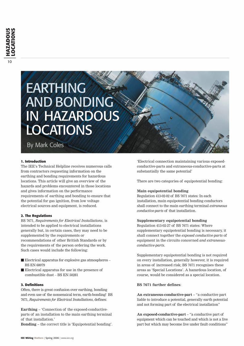
1. IntroductionThe IEE’s Technical Helpline receives numerous callsfrom contractors requesting information on theearthing and bonding requirements for hazardouslocations. This article will give an overview of thehazards and problems encountered in those locationsand gives information on the performancerequirements of earthing and bonding to ensure thatthe potential for gas ignition, from low voltageelectrical sources and equipment, is reduced.
2. The RegulationsBS 7671, Requirements for Electrical Installations, isintended to be applied to electrical installationsgenerally but, in certain cases, they may need to besupplemented by the requirements orrecommendations of other British Standards or bythe requirements of the person ordering the work.Such cases would include the following:
Electrical apparatus for explosive gas atmospheres –BS EN 60079
Electrical apparatus for use in the presence ofcombustible dust – BS EN 50281
3. DefinitionsOften, there is great confusion over earthing, bondingand even use of the nonsensical term, earth-bonding! BS7671, Requirements for Electrical Installations, defines:
Earthing – ‘Connection of the exposed-conductive-parts of an installation to the main earthing terminalof that installation.’Bonding – the correct title is ‘Equipotential bonding’.
‘Electrical connection maintaining various exposed-conductive-parts and extraneous-conductive-parts atsubstantially the same potential’
There are two categories of equipotential bonding:
Main equipotential bondingRegulation 413-02-02 of BS 7671 states: In eachinstallation, main equipotential bonding conductorsshall connect to the main earthing terminal extraneousconductive-parts of that installation.
Supplementary equipotential bondingRegulation 413-02-27 of BS 7671 states: Wheresupplementary equipotential bonding is necessary, itshall connect together the exposed conductive-parts ofequipment in the circuits concerned and extraneous-conductive-parts.
Supplementary equipotential bonding is not requiredon every installation, generally however, it is requiredin areas of increased risk; BS 7671 recognises theseareas as ‘Special Locations’. A hazardous location, ofcourse, would be considered as a special location.
BS 7671 further defines:
An extraneous-conductive-part – “a conductive partliable to introduce a potential, generally earth potentialand not forming part of the electrical installation”
An exposed-conductive-part – “a conductive part ofequipment which can be touched and which is not a livepart but which may become live under fault conditions”
EARTHINGAND BONDING IN HAZARDOUSLOCATIONSBy Mark Coles
HA
ZAD
OU
SLO
CATI
ON
S
IEE Wiring Matters | Spring 2006 | www.iee.org
11
Defining Hazardous LocationsBS EN 60079-14: 2003, Electrical apparatus forexplosive gas atmospheres – Part 14: Electricalinstallations in hazardous areas (other than mines),defines the following: Explosive atmosphere Explosive gas atmosphere Hazardous area
Note – The ATEX 137 Directive has adopted the concept ofspace instead of area; by definition, area is a two-dimen-sional concept, space is a three-dimensional concept.
In line with BS EN 60079-10: 2003, Electrical apparatus forexplosive gas atmospheres – Part 10: Classification ofhazardous areas, this article will consider hazardouslocations where gas ignition from low voltageelectrical sources is possible but, for the purposesof this article, the following locations will not beconsidered:a) mines susceptible to firedampb) the processing and manufacture of explosivesc) areas where a risk may arise due to the presence of
ignitable dusts or fibresd) catastrophic failures which are beyond the concept
of abnormalitye) rooms used for medical purposesf) areas where the presence of flammable mist may
give rise to an unpredictable risk and which requirespecial consideration
Explosive atmosphereMixture with air, under atmospheric conditions, offlammable substances in the form of gas, vapour, mistor dust, in which after ignition, combustion spreadsthroughout the unconsumed mixture.
Explosive gas atmosphereMixture with air, under atmospheric conditions, offlammable substances in the form of gas or vapour, in which after ignition, combustion spreads throughoutthe unconsumed mixture.
Hazardous areaArea in which an explosive gas atmosphere is present,or may be expected to be present, in quantities such as to require special precautions for theconstruction, installation and use of apparatus.
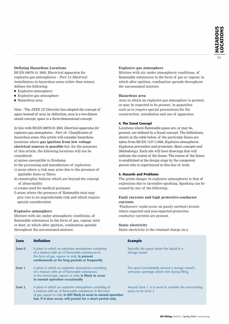
4. The Zonal ConceptLocations where flammable gases are, or may be,present, are defined by a Zonal concept. The definitions,shown in the table below, of the particular Zones aretaken from BS EN 1127-1:1998, Explosive atmospheres.Explosion prevention and protection. Basic concepts andMethodology. Each site will have drawings that willindicate the extent of the Zones. The extent of the Zonesis established at the design stage by the competentperson who is experienced in this line of work.
5. Hazards and ProblemsThe prime danger in explosive atmospheres is that ofexplosions due to incendive sparking. Sparking can becaused by any of the following:
Fault currents and high protective-conductorcurrents‘Flashovers’ could occur on poorly earthed circuitswhere expected and non-expected protective-conductor currents are present.
Static electricityStatic electricity is the retained charge on a
Zone Definition Example
Zone 0 A place in which an explosive atmosphere consisting Typically, the space above the liquid in a of a mixture with air of flammable substances in storage vessel. the form of gas, vapour or mist, is present continuously or for long periods or frequently
Zone 1 A place in which an explosive atmosphere consisting The space immediately around a storage vessel’s of a mixture with air of flammable substances vent-pipe openings which vent during filling.in the formof gas, vapour or mist, is likely to occur in normal operation occasionally
Zone 2 A place in which an explosive atmosphere consisting of Around Zone 1, it is usual to consider the surroundinga mixture with air of flammable substances in the form space to be Zone 2of gas, vapour or mist, is NOT likely to occur in normal operationbut, if it does occur, will persist for a short period only.
HA
ZAD
OU
SLO
CATI
ON
S
12
IEE Wiring Matters | Spring 2006 | www.iee.org
conductor. All the energy stored on the conductor canbe released in one arc or ‘spark’ to catastrophic effect.To retain charge on a conductor, it has to be insulatedfrom other conductors and insulated from earth bymeans of a non-conductor. Sparking, due to staticelectricity, can be avoided by using recognisedearthing and equipotential bonding techniques.
Static electricity is generated in many ways, including: the flow of liquids the mixing of powders the production of sprays the contact and separation of solids
Static electricity causes problems in manyindustries, such as chemical, pharmaceutical,petroleum, etc.
Static electricity-discharges from a person can beminimized by providing an adequately-conductingpath between the person and earth through theirfootwear and the floor. BS 7193 gives requirements fortwo types of rubber footwear. Specifications forconducting-flooring materials and for such floors afterlaying are given in BS 2050 and BS 3187.
The phenomena that is Static Electricity is coveredin great depth in two parts of BS 5958: 1991, Code ofpractice for Control of undesirable static electricity:Part 1: General considerations, and Part 2: Recommendations for particular industrial situations.
Lightning protection systemRegulation 413-02-02 of BS 7671 requires that in eachinstallation, main equipotential bonding conductorsshall connect to the main earthing terminal extraneous-conductive-parts of that installation, including thelightning protection system. However, the designer ofthe installation, who is a competent person, may decidethat, due to particular risks, main equipotential bondingof the lightning protection system should be avoided.For further information, consult: BS 6651, Code ofpractice for protection of structures against lightningand BS 7430, Code of practice on earthing.
The electrical supplyThe following electrical systems are NOT suitable foruse in hazardous locations: TN-C TN-C-S (PME)
In TN-C and TN-C-S (PME) supplies, the neutralconductor is also the earthing conductor, therefore,there could be a potential difference between the mainearthing terminal of the installation and the general
mass of earth. Incendive sparking could then occurbetween the earth of the electrical installation andany extraneous metalwork which is in contact withthe general mass of earth.
Electrical equipmentElectrical apparatus for use in hazardous locationsmust be suited for the gas group, the temperature classification and that particular protection concept.
6. Performance requirements of earthing & bondingconductors in hazardous locationsIn this section, we’ll look at the sizing of conductorsand desired values of resistance.
Sizing of earthing conductorsIn accordance with Regulation 543-01-03 of BS 7671,two methods may be used to size earthing conductorsor circuit protective conductors (CPCs); the first is theadiabatic equation, the second is Table 54G.
Sizing of equipotential bonding conductorsIn accordance with Regulation 547-02-01 of BS 7671and excluding PME as previously stated, a mainequipotential bonding conductor shall have a CSA notless than half the CSA required for the earthing conductor of the installation and not less than 6 mm2.The cross-sectional area need not exceed 25 mm2 ifthe bonding conductor is of copper or a CSA affordingequivalent conductance in other metals.
Further, Regulation group 547-03 of BS 7671,requires that supplementary equipotential bonding conductors are sized according to both theirparticular application and whether they aremechanically protected. NOTE – Table 10B of the IEEpublication, The On-Site Guide, is a handy referenceguide for sizing such conductors.
Further, Guidance Note 3, Inspection and Testing,published by the IEE, advises that supplementary equipotential bonding conductors should have aresistance of 0.05Ω, or less.
Eliminating static electricityBS 5958-1: 1991, Code of practice for Control ofundesirable static electricity – Part 1: Generalconsiderations, states that to retain a significantelectrostatic charge, a resistance to earth in excess of1MΩ is required. Generally, resistance between metalsin good contact rarely exceeds a few ohms. A valueless than 100Ω is readily attainable and is unlikely todeteriorate with time to a level above 1MΩ unlessserious corrosion is present.
HA
ZAD
OU
SLO
CATI
ON
S
IEE Wiring Matters | Spring 2006 | www.iee.org
17
Equipotential bonding connectionsBS EN 60079-0:2004, Electrical apparatus for explosivegas atmospheres – Part 0: General requirements, requires that equipotential bonding connectionsshould only be made through designed connectionpoints and not rely on fortuitous contact. Allconnections should be secure against self-loosening.This requires the use of materials that are designedfor that particular application and fit for purpose.
It is worth noting that equipotential bondingconductors would not be required where insulationensures that circulating currents cannot flow.However, provision shall be made for adequateearthing of isolated exposed-conductive-parts. Theinsulation of such parts shall be capable ofwithstanding a test of 100 V r.m.s for 1 min.
Potential equalisationBS EN 60079-14:2003, Electrical apparatus for explosivegas atmospheres – Part 14: Electrical installations inhazardous areas (other than mines), states thatpotential equalization is required for installations inhazardous areas. In effect, this means that all exposedand extraneous conductive parts are connected to theequipotential bonding system. Like other installationsin non-hazardous locations, the bonding system mayinclude protective conductors, metal conduits, metalcable sheaths, steel wire armouring and metallic partsof structures. Exposed conductive parts need not beseparately connected to the equipotential bondingsystem if they are firmly secured to and are inmetallic contact with structural parts or piping whichare connected to the equipotential bonding system.
Intrinsic safetyOne type of protective system used in hazardouslocations is Intrinsic safety. There are two categoriesof intrinsic safety, namely, Category ia; may be usedin hazardous area Zones 0, 1 & 2, and category ib; maybe used in hazardous area Zones 1 & 2. By definition,an intrinsic safety system will limit the energyavailable in the hazardous location to a level such thatignition of the flammable atmosphere could not occur.Limitation of energy is achieved by using one of twotypes of barrier; a Shunt Diode Barrier orGalvanically Isolated Barriers. The intrinsic safetyearth is a direct connection between the earthterminal of the shunt diode and the main earthingterminal of the electrical supply.
BS EN 50020:2002 – Electrical apparatus for potentiallyexplosive atmospheres – Intrinsic safety ‘i’, states:
CPC to be ≥ 4mm2 (length & further mechanicalprotection may warrant larger CSA)
Insulation of dedicated CPC 1 Ω maximum (current practice is to achieve 0.1 Ω) All screens to be earthed All unused cores to be terminated at both ends and
earthed as documentation stipulates
7. SummaryTo summarise, earthing and bonding is required on allcircuits, unless the site documentation or design statesotherwise. Equipotential bonding should connect allexposed and extraneous-conductive parts, unless, again,the site documentation states otherwise. All conductorsshould be sized appropriately, in accordance withRegulation 543-01-03 of BS 7671. All earthing and bondingconnections should be correctly installed and connectionsmade at the designed-connection points; never rely onfortuitous contact. Where mechanical connection points,such as threaded conduit and SWA cable armouring lugsare utilised, continuity should be assured
8. Bibliography and further readingThe following publications will provide furtherinformation: BS 7671: 2001 (2004) Requirements for electrical
installations Guidance Note 3 – Inspection and Testing, Inc AMD
No.2 : 2004, IEE Publications On-Site Guide to BS 7671: 2001 (2004), IEE Publications BS 7430: 1998 Code of practice for earthing BS EN 60079 Electrical apparatus for explosive gas
atmospheres (suite of standards) ATEX 95 Directive ATEX 137 Directive BS EN 1127-1:1998 Explosive atmospheres. Explosion
prevention and protection. Basic concepts andMethodology.
BS 5958 Code of practice for Control of undesirablestatic Electricity (suite of standards)
BS 7193 Specification for lined lightweight rubberovershoes and overboots
BS 2050 Specification for electrical resistance ofconducting and antistatic products made from flexiblepolymeric material
BS 3187 Specification for electrically conductingrubber flooring
BS 6651 Code of practice for protection of structuresagainst lightning
BS EN 50020:2002 Electrical apparatus for potentiallyexplosive atmospheres – intrinsic safety ‘i’
DSEAR Regulations 2002

PO
RTA
BLE
&H
AN
DH
ELD
EQ
UIP
.
18
IEE Wiring Matters | Spring 2006 | www.iee.org
MOST PORTABLE equipment being used outdoors issupplied via a flexible cord fed from either a socket-outlet or a flexible cable/cord outlet plate. Thiscable/cord may have a high susceptibility to damagefor the following reasons: the lead is trailed whilst the equipment is in use
giving rise to abrasion, twisting and straininginfluences
connected items such as lawnmowers, hedge-cutters
and power tools have moving parts capable ofcausing damage that may expose live parts
equipment and the supply cables/cords in exteriorinstallations are prone to exposure to moisture as aresult of precipitation
The presence of moisture as a result of rain or evenheavy dew can result in users of portable equipmentoutdoors having damp feet. This will inevitably resultin a lowered contact resistance of the person with thegeneral mass of earth, further increasing shock risk,particularly in the case of handheld equipment.
BS 7671 requirements for portable equipment These increased risk factors mentioned above arereflected in the specific requirements of 471-16 whichrelates to supplies to portable equipment outdoorssupplied via a socket-outlet and is reproduced below:471-16-01 A socket-outlet rated at 32 A or less which mayreasonably be expected to supply portable equipment foruse outdoors shall be provided with supplementaryprotection to reduce the risk associated with direct contactby means of a residual current device having thecharacteristics specified in Regulation 412-06-02(ii).
This regulation does not apply to a socket-outletsupplied by a circuit incorporating one or more of theprotective measures specified in items (i) to (iii) belowand complying with the Regulations indicated:(i) protection by SELV (see Regulations 411-02 and 471-02)(ii) protection by electrical separation (see Regulations
PERMITTEDFORMS OFSUPPLY FORPORTABLE ANDHANDHELDEQUIPMENTBy Jon Elliott
PO
RTA
BLE
&H
AN
DH
ELD
EQ
UIP
.
IEE Wiring Matters | Spring 2006 | www.iee.org
19
413-06 and 471-12)(iii) protection by automatic disconnection and reduced
low voltage systems (see Regulation 471-15).
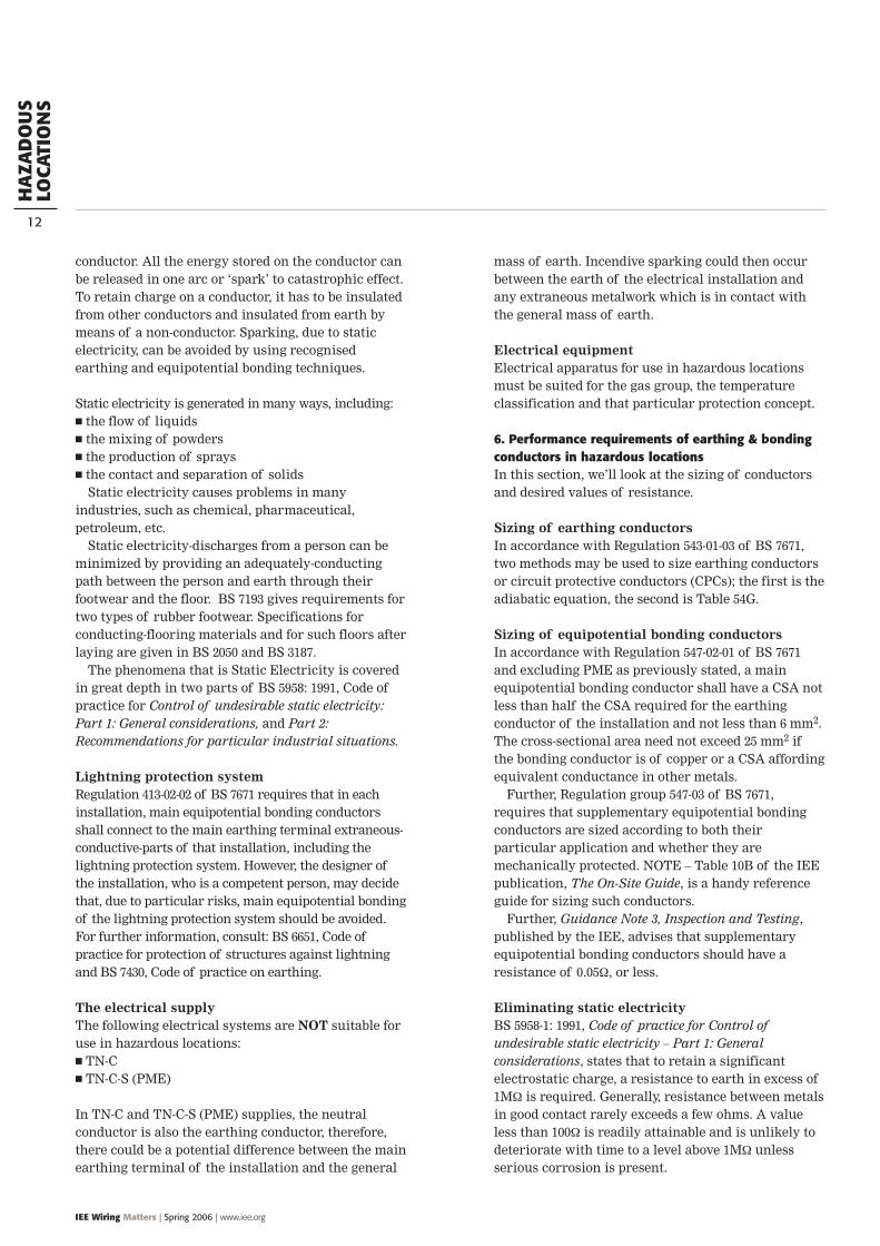
Regulation 471-16-02 relates to supplies to portableequipment outdoors supplied by means other than asocket and is reproduced below:471-16-02 Except where one or more of the protectivemeasures specified in items (i) to (iii) of Regulation471-16-01 are applied in compliance with thecorresponding regulations stated therein, a circuitsupplying portable equipment for use outdoors,connected other than through a socket-outlet bymeans of flexible cable or cord having a current-carrying capacity of 32 A or less, shall be providedwith supplementary protection to reduce the riskassociated with direct contact, by means of a residualcurrent device having the characteristics specified inRegulation 412-06-02(ii).
Both of the above Regulations make reference tothe use of RCDs that meet the requirements ofRegulation 412-06-02 (ii) to provide supplementaryprotection against direct contact. That is, the RCDshould have a rated residual current (In) notexceeding 30 mA and an operating time notexceeding 40 mS at 5 In.
The use of such RCDs to provide supplementaryprotection against direct contact is commonlyemployed. However, as can be seen from reference tothe two Regulations reproduced above, the use ofsuch RCDs is not the sole method of protectionsuitable for supplies to portable equipmentoutdoors.
The use of a 30 mA RCD is not required where thesource of supply originates from a circuit that isprotected by SELV electrical separation automatic disconnection and reduced low voltage
systems
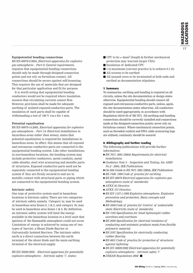
SELVSELV is defined in BS 7671 as “An extra-low voltagesystem which is electrically separated from Earthand from other systems in such away that a singlefault cannot give rise to the risk of electric shock”.
The supply for a SELV system may be derivedfrom the following sources: a safety isolating transformer in which there is
no connection between the output winding andthe body or to earth
a motor-generator set in which the windings
provide isolation equivalent to that provided by thewindings of an isolating transformer
a battery
The maximum permitted voltages of 50 V a.c. or 120V ripple-free d.c. limit the employment of SELV as asource of supply for portable tools and equipment.However, there are a number of instances where theuse of SELV is the only means of supply permitted forhandheld or portable items of electrical equipment.These are summarised later within this article.
Electrical separationIn the case of using electrical separation it isnecessary to make reference to Regulation 471-12-01which is reproduced below:
Figure 2: Separated extra-low voltage supply derived from a transformer
Figure 1: RCD under fault conditions
PO
RTA
BLE
&H
AN
DH
ELD
EQ
UIP
.
20
IEE Wiring Matters | Spring 2006 | www.iee.org
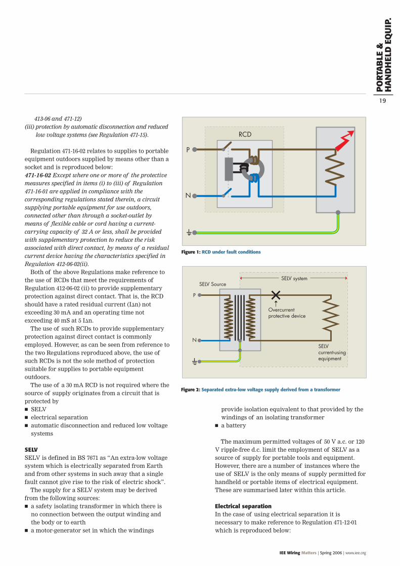
471-12-01 This measure is intended, in an individualcircuit, to prevent shock current through contact withexposed-conductive-parts which might be energised by afault in the basic insulation of that circuit. It may beapplied to the supply of any individual item ofequipment by means of a transformer complying withBS 3535 the secondary of which is not earthed, or asource affording equivalent safety. Its use to supplyseveral items of equipment from a single separatedsource is recognised in the Regulations only for specialsituations under effective supervision, where specifiedby a suitably qualified electrical engineer. Where themeasure is used to supply several items of equipmentfrom a single source, a warning notice complying withRegulation 514-13-02 shall be fixed in a prominentposition adjacent to every point of access to the locationconcerned.
The actual requirements placed upon the designerof the installation vary depending upon the numberof items of equipment that is intended to supply.
Where only a single item of equipment is suppliedby an isolating transformer to BS 3535 requirements,the following measures are required by 413-06-03
There should be no connection between theseparated circuit and any other circuit, or to Earth
A flexible cable/cord liable to mechanical damageshould be visible throughout its length
It is preferred that a separate wiring system shouldbe used for the separated circuit (althoughmulticore cables without magnetic sheath orinsulated conductors in an insulated enclosure arepermitted if the rated voltage of the cables is notless than the highest voltage likely to occur andeach circuit is protected against overcurrent)
Every live part of each separate circuit shall beelectrically separated from all other circuits to astandard not less than that provided between inputand output windings of an isolating transformer toBS 3535
Regulation 413-06-04 requires that no exposed-conductive-part of the separated circuit shall beconnected to either the protective conductor of thesource circuit, or to any exposed-conductive-parts ofany other circuit.
Where it is intended to use a single separatedsource to supply a number of items of equipment,where this protective measure is permitted by BS7671, it will be necessary to meet the relevantrequirements of 413-06 (Protection by electricalseparation).
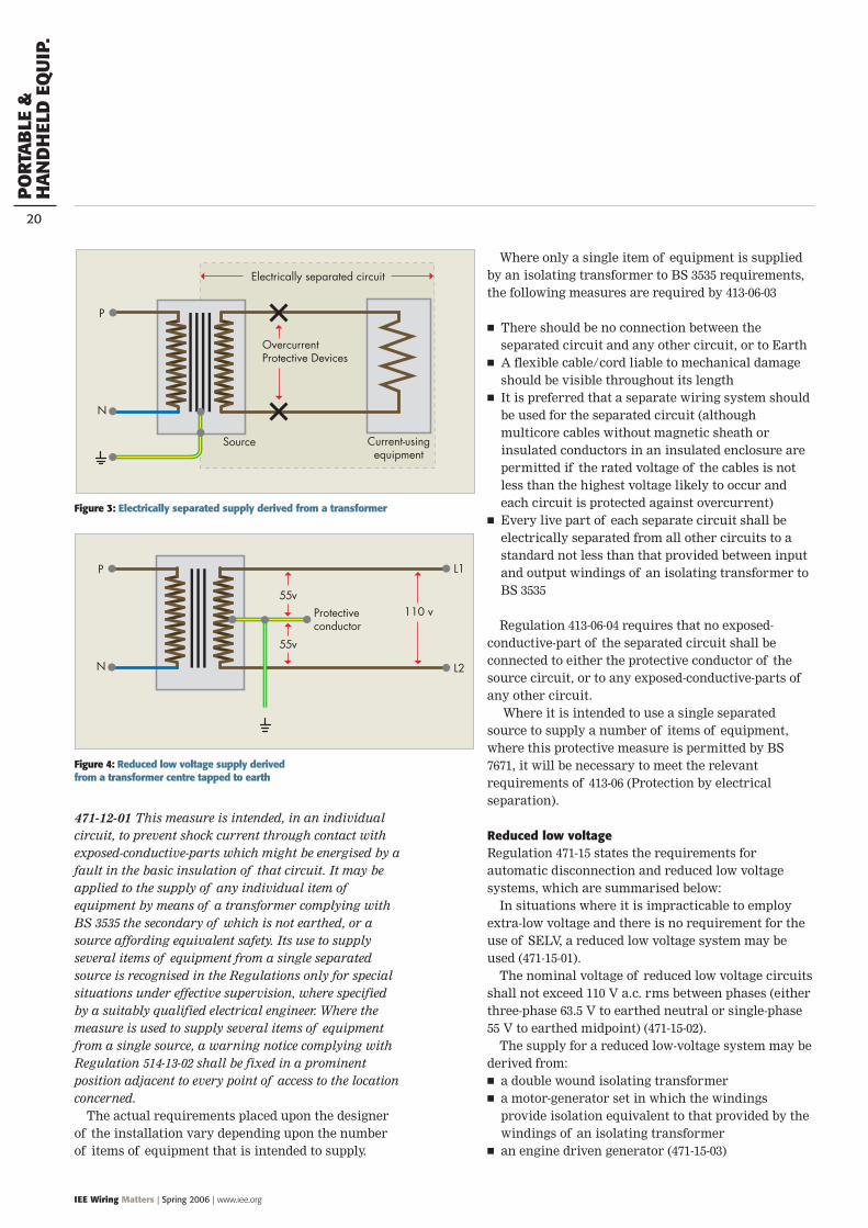
Reduced low voltageRegulation 471-15 states the requirements forautomatic disconnection and reduced low voltagesystems, which are summarised below:
In situations where it is impracticable to employextra-low voltage and there is no requirement for theuse of SELV, a reduced low voltage system may beused (471-15-01).
The nominal voltage of reduced low voltage circuitsshall not exceed 110 V a.c. rms between phases (eitherthree-phase 63.5 V to earthed neutral or single-phase55 V to earthed midpoint) (471-15-02).
The supply for a reduced low-voltage system may bederived from: a double wound isolating transformer a motor-generator set in which the windings
provide isolation equivalent to that provided by thewindings of an isolating transformer
an engine driven generator (471-15-03)
P D
Figure 4: Reduced low voltage supply derived from a transformer centre tapped to earth
Figure 3: Electrically separated supply derived from a transformer
PO
RTA
BLE
&H
AN
DH
ELD
EQ
UIP
.
IEE Wiring Matters | Spring 2006 | www.iee.org
21
The neutral (star) point on secondary windings ofthree-phase transformers or generators, or the mid-point of the secondary windings of single-phasetransformers or generators shall be connected toearth (471-15-04).
Protection against direct contact should be providedby insulation or by a barrier/enclosure (471-15-05)
Protection against indirect contact shall beprovided by an overcurrent protective device such asa fuse or MCB, or by an RCD placed in each phaseconductor such that the earth fault loop impedanceat any point of utilisation permits a disconnectiontime not exceeding 5 seconds. Where an RCD is used,the product of rated residual current (In) and theearth fault loop impedance shall not exceed 50 (471-15-06).
All plugs, socket-outlets and cable couplers used in areduced low voltage system shall have a protectiveconductor contact and not be dimensionallyinterchangeable with plugs, socket-outlets and cablecouplers within the same installation for use at othervoltages or frequencies (471-15-07).
Summary of BS 7671 requirements for supplies toportable and handheld equipmentThere are a number of instances where BS 7671makes specific reference to the type of protection thatis suitable for supplies to portable and handheldequipment. These are summarised below:
Supplies for portable equipment outdoors (471-16-01 & 471-16-02) RCD having a rated residual operating current (In)
not exceeding 30 mA and an operating time notexceeding 40 mS at 5 In (412-06-02)
SELV (411-02 & 471-02) Electrical separation (413-06 & 471-12) Automatic disconnection and reduced low voltage
systems (471-15)
Swimming pools (Section 602)Note: Socket-outlets provided in a swimming poollocation are provided for the intention ofcleaning/maintenance purposes carried out when thepool is not in use. Zone A – None permitted Zone B – BS EN 60309-2 socket-outlets may only be
installed if it is not possible to position themoutside zone B if they are:– More than 1.25 m beyond the border of zone A, and– At least 0.3 m above the floor level, and– Protected by either:
– 30 mA RCD– Electrical separation, where the safety isolating
transformer is placed outside zones A, B and C Zone C – BS EN 60309-2 socket-outlets
Construction sites (section 604)Note: All plugs and sockets used should comply with BSEN 60309-2 regardless of voltage being supplied (604-12-02) Supplies for portable hand lamps for use in
confined or damp locations – SELV Portable hand lamps for general use; portable hand-
held tools and local lighting up to 2 kW – 1-phasereduced low voltage
Portable hand-held tools and local lighting up to 2 kW; small mobile plant up to 3.75 kW – 3-phasereduced low voltage
The use of 230 V to supply portable equipmentsupplied via a 30 mA RCD, although not stated in BS7671 is permitted (HSE Guidance Note HSG 141refers). However, the use of automatic disconnectionand reduced low voltage supply as prescribed in BS7671 is the preferred system for use on constructionsites in the United Kingdom.
There is a possibility of damage occurring to thesensitive operating mechanism of the RCD as aresult of the harshness of the environment inherenton a construction site. Any such damage may renderthe RCD inoperative, removing any protection that itwas intended to provide. As such, attention must begiven to correct positioning of RCDs and to thechoice of enclosures employed. Where an RCD isprovided on a construction site, for reasons of safety,its correct operation should be confirmed prior toeach use.
Agricultural and horticultural premises (section 605) SELV Socket-outlets protected by 30 mA RCD (605-03-01)
Restrictive conductive locations (section 606) Socket-outlets or other supplies for hand lamps SELV (606-04-02) Socket-outlets or other supplies for hand-held
tools (606-04-04)– SELV– Electrical separation where only one socket-
outlet or piece of equipment is connected to each secondary winding of a transformer (606-04-01(iv))
PO
WER
FACT
OR
COR
REC
TIO
N
22
IEE Wiring Matters | Spring 2006 | www.iee.org
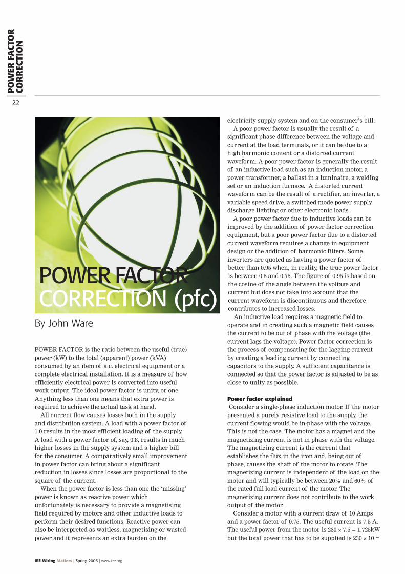
POWER FACTOR is the ratio between the useful (true)power (kW) to the total (apparent) power (kVA)consumed by an item of a.c. electrical equipment or acomplete electrical installation. It is a measure of howefficiently electrical power is converted into usefulwork output. The ideal power factor is unity, or one.Anything less than one means that extra power isrequired to achieve the actual task at hand.
All current flow causes losses both in the supplyand distribution system. A load with a power factor of1.0 results in the most efficient loading of the supply.A load with a power factor of, say, 0.8, results in muchhigher losses in the supply system and a higher billfor the consumer. A comparatively small improvementin power factor can bring about a significantreduction in losses since losses are proportional to thesquare of the current.
When the power factor is less than one the ‘missing’power is known as reactive power whichunfortunately is necessary to provide a magnetisingfield required by motors and other inductive loads toperform their desired functions. Reactive power canalso be interpreted as wattless, magnetising or wastedpower and it represents an extra burden on the
electricity supply system and on the consumer’s bill.A poor power factor is usually the result of a
significant phase difference between the voltage andcurrent at the load terminals, or it can be due to ahigh harmonic content or a distorted currentwaveform. A poor power factor is generally the resultof an inductive load such as an induction motor, apower transformer, a ballast in a luminaire, a weldingset or an induction furnace. A distorted currentwaveform can be the result of a rectifier, an inverter, avariable speed drive, a switched mode power supply,discharge lighting or other electronic loads.
A poor power factor due to inductive loads can beimproved by the addition of power factor correctionequipment, but a poor power factor due to a distortedcurrent waveform requires a change in equipmentdesign or the addition of harmonic filters. Someinverters are quoted as having a power factor ofbetter than 0.95 when, in reality, the true power factoris between 0.5 and 0.75. The figure of 0.95 is based onthe cosine of the angle between the voltage andcurrent but does not take into account that thecurrent waveform is discontinuous and thereforecontributes to increased losses.
An inductive load requires a magnetic field tooperate and in creating such a magnetic field causesthe current to be out of phase with the voltage (thecurrent lags the voltage). Power factor correction isthe process of compensating for the lagging currentby creating a leading current by connectingcapacitors to the supply. A sufficient capacitance isconnected so that the power factor is adjusted to be asclose to unity as possible.
Power factor explainedConsider a single-phase induction motor. If the motor
presented a purely resistive load to the supply, thecurrent flowing would be in-phase with the voltage.This is not the case. The motor has a magnet and themagnetizing current is not in phase with the voltage.The magnetizing current is the current thatestablishes the flux in the iron and, being out ofphase, causes the shaft of the motor to rotate. Themagnetizing current is independent of the load on themotor and will typically be between 20% and 60% ofthe rated full load current of the motor. Themagnetizing current does not contribute to the workoutput of the motor.
Consider a motor with a current draw of 10 Ampsand a power factor of 0.75. The useful current is 7.5 A.The useful power from the motor is 230 × 7.5 = 1.725kWbut the total power that has to be supplied is 230 × 10 =
By John Ware
POWER FACTOR CORRECTION (pfc)
PO
WER
FACT
OR
COR
REC
TIO
N
IEE Wiring Matters | Spring 2006 | www.iee.org
23
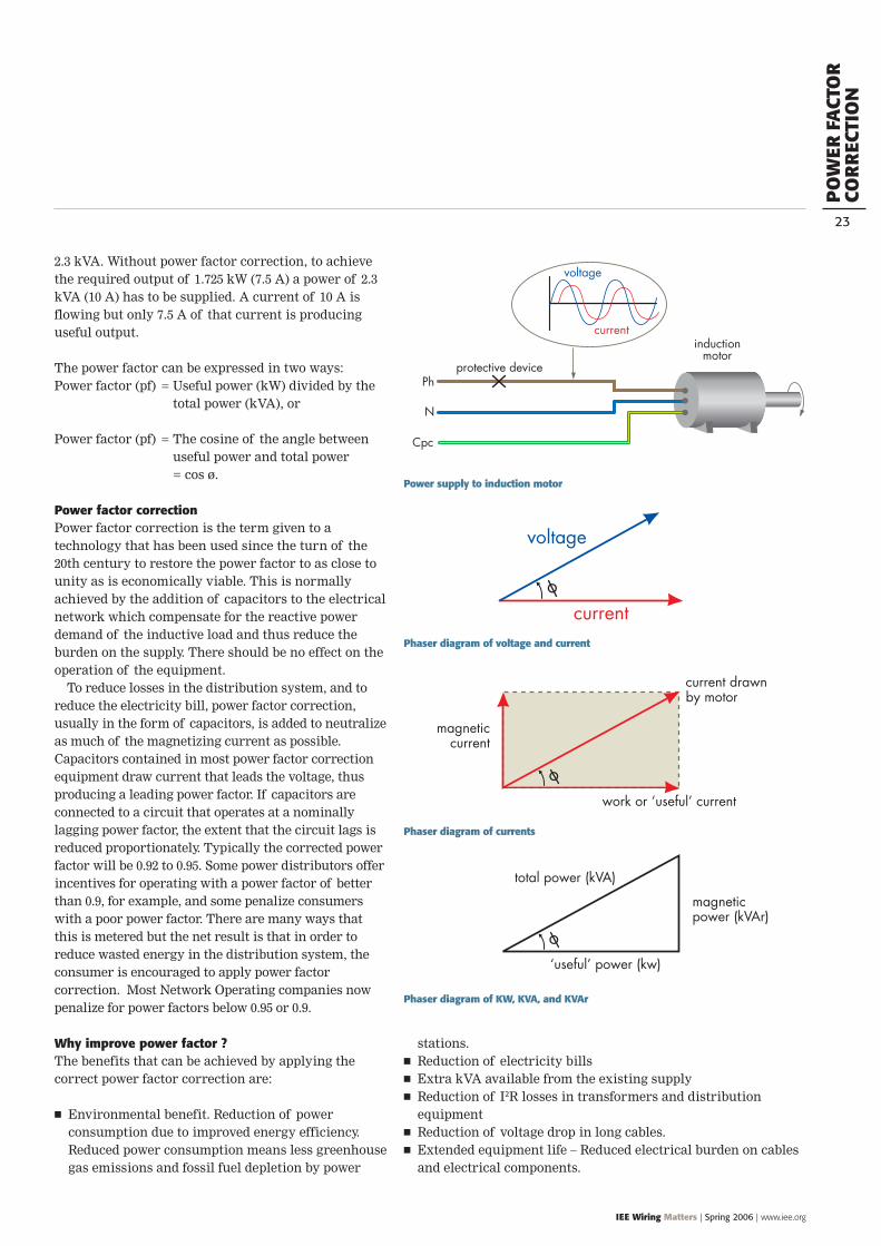
2.3 kVA. Without power factor correction, to achievethe required output of 1.725 kW (7.5 A) a power of 2.3kVA (10 A) has to be supplied. A current of 10 A isflowing but only 7.5 A of that current is producinguseful output.
The power factor can be expressed in two ways:Power factor (pf) = Useful power (kW) divided by the
total power (kVA), or
Power factor (pf) = The cosine of the angle betweenuseful power and total power= cos ø.
Power factor correctionPower factor correction is the term given to atechnology that has been used since the turn of the20th century to restore the power factor to as close tounity as is economically viable. This is normallyachieved by the addition of capacitors to the electricalnetwork which compensate for the reactive powerdemand of the inductive load and thus reduce theburden on the supply. There should be no effect on theoperation of the equipment.
To reduce losses in the distribution system, and toreduce the electricity bill, power factor correction,usually in the form of capacitors, is added to neutralizeas much of the magnetizing current as possible.Capacitors contained in most power factor correctionequipment draw current that leads the voltage, thusproducing a leading power factor. If capacitors areconnected to a circuit that operates at a nominallylagging power factor, the extent that the circuit lags isreduced proportionately. Typically the corrected powerfactor will be 0.92 to 0.95. Some power distributors offerincentives for operating with a power factor of betterthan 0.9, for example, and some penalize consumerswith a poor power factor. There are many ways thatthis is metered but the net result is that in order toreduce wasted energy in the distribution system, theconsumer is encouraged to apply power factorcorrection. Most Network Operating companies nowpenalize for power factors below 0.95 or 0.9.
Why improve power factor ?The benefits that can be achieved by applying thecorrect power factor correction are:
Environmental benefit. Reduction of powerconsumption due to improved energy efficiency.Reduced power consumption means less greenhousegas emissions and fossil fuel depletion by power
stations. Reduction of electricity bills Extra kVA available from the existing supply Reduction of I2R losses in transformers and distribution
equipment Reduction of voltage drop in long cables. Extended equipment life – Reduced electrical burden on cables
and electrical components.
Phaser diagram of KW, KVA, and KVAr
Phaser diagram of currents
Power supply to induction motor
Phaser diagram of voltage and current
PO
WER
FACT
OR
COR
REC
TIO
N
IEE Wiring Matters | Spring 2006 | www.iee.org
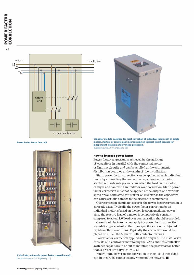
How to improve power factorPower factor correction is achieved by the addition of capacitors in parallel with the connected motor or lighting circuits and can be applied at the equipment,distribution board or at the origin of the installation.
Static power factor correction can be applied at each individualmotor by connecting the correction capacitors to the motorstarter. A disadvantage can occur when the load on the motorchanges and can result in under or over correction. Static powerfactor correction must not be applied at the output of a variablespeed drive, solid state soft starter or inverter as the capacitorscan cause serious damage to the electronic components.
Over-correction should not occur if the power factor correction iscorrectly sized. Typically the power factor correction for anindividual motor is based on the non load (magnetizing) powersince the reactive load of a motor is comparatively constantcompared to actual kW load over compensation should be avoided.
Care should be taken when applying power factor correctionstar/delta type control so that the capacitors are not subjected torapid on-off-on conditions. Typically the correction would beplaced on either the Main or Delta contactor circuits.
Power factor correction applied at the origin of the installationconsists of a controller monitoring the VAr’s and this controllerswitches capacitors in or out to maintain the power factor betterthan a preset limit (typically 0.95).
Where ‘bulk’ power factor correction is installed, other loadscan in theory be connected anywhere on the network.
Power Factor Correction Unit
24
Capacitor module designed for local correction of individual loads such as singlemotors, starters or control gear incorporating an integral circuit breaker forindependent isolation and overload protection. [Illustration courtesy of PFC Engineering Ltd]
A 324 kVAr, automatic power factor correction unit.[Illustration courtesy of PFC Engineering Ltd]