Embed Size (px)
Citation preview
51 1
An Investigation of Field·And Laboratory-Compacted AsphaltRubber, SMA, Recycled and Conventional Asphalt-Concrete Mixes
Using SHRP Project A-003A Equipment
Iohn Harvey', Carl Monisrnith2 and Jorge Sousa'
Introduction
It has long been documented that different laboratory compaction methods can produce specimens with different degrees of resistance to permanent deformation as measured in laboratory testing (Vallerga (1); Sousa et aI. [2]; Sousa et aI. (3)). The task of the experiment described in this paper was to compare the performance of laboratory-compacted specimens of asphalt-aggregate mix to fieldcompacted specimens. with the objective of estimating which laboratory compaction method produces specimens most similar to those produced by field compaction. The laboratOry methods considered were Texas gyratory, rolling wheel, kneading, SHRP gyratory, and Marshall hammer compaction.
It has recently been shown that the first three of these compaction methods produces specimens tha t have significantly different resistance to the permanent deformation caused by repetitive shear loads (Harvey and Monismitb [4}). The differences in permanent-deformation response found in that study have been explained in terms of the characteristic aggregate structures and binder films produced by each compaction method, with Texas gyratory compaction producing specimens with the least permanent shear deformation resistance, kneading compaction producing specimens with the most resistance, and rolling-wheel compaction producing specimens with resistance between those of the preceding methods. Differences in aggregate orientation produced by each compaction method have been verified by image analysis of plane sections cut from spedmens (Harvey et at. [5]) which indicated that Texas gyratory compaction produces little or no aggregate orientation, while rolling-wheel compaction does produce observable aggregate orientation. Aggregate orientation is ind icative of aggregate structures which will have a greater tendency to resist
'v ...... ~ -.... &,'-u -' 'no. -.. H....ytfl'rot_ of c;.a r.oc ......... u.;. ..... ;,y of Colif ...... But.c.IqI CA 'OU--, Applio<l PIovil>f Todoo.oIofioo, Ricb.ood CA n.. onJ _Iiooo ..... ....s. ~ 0<. H ...... .,.
Si2 HuTey, Monismith and Sousa
permanent shear deformation. Although at lower temperatures it may not play much role in resisting permanent shear deformation, the effects of aggregate structure can be expected to become more important as test temperatures increase.
Research has also shown that for most dense-graded asphalt concrete mixes the resistance to permanent shear deformation in repetitive simple shear testing increases at lower air+void contents (measured using parafilm) (Sousa et aI. {3 }, Harvey and Monismith [4J), with maximum resistance occurring at air-void contents of approximately three percent for laboratory specimens (Sousa et a1. [6], Sousa [7]). Other research has shown that, for 40 field sites in the United States and Canada, large rut depths only occurred when the air-void content was less than 3.0 percent (Sousa and Solaimanian [8]). These fi eld sections were not compacted to this air-void content but rather densified by traffic. These data indicate that when the mix is not sufficiently resistant to pennanent shear deformation at air-void contents of approximately three percent, it will continue to density and shear. For this reason, it is recommended that laboratory specimens of dense-graded mix be compacted to approximately three percent airvoids for mix design using the repetitive simple shear test (Sousa and Solaimanian [81. Sousa et al. (9».
An NCHRP project (Von Quintus et al. (10)) previously presented data pertaining to the question of which laboratory compaction method produces specimens most like field-compacted specimens. Laboratory specimens compacted using the Marshall hammer, ASTM kneading compactor, Texas gyratory compactor, Arizona vibracory/kneading compactor, and a steel wheel simulator were compared with cores taken from pavement test seclions compacted using various combinations of equipment. UnfortunateJy, due to quality assurance problems in the field, field cores from four of the five test sections had relatively high air-void contents. The conclusion of the NCHRP repon - that the Texas gyratory compactor best matches field results but that there is linle difference between the gyratory, kneading, and steel wheel roller compaction methods - was thus primarily indicative of specimens with high air-void contents. The results of the later comparison of laboratory specimens demonstrated a significant correlation between compaction method and air-void content, and showed that differences in permanent shear defonnation resistance are not as great at air-void contents between 7 and 9 percent as at air-void contents between 3 and 5 percent (Harvey and Monismith [4)).
In the compaction study of the Strategic Highway Research
A-003A Equipment 513
rogram (SHRP) Project A-003A (Sousa et al. [3]), limited omparisons of the permanent-defonnation behavior of well compacted ield- and Jaborarory...:ompacted specimens from the same mix, ompacted to the same air-void contents, indicated that kneading ;ompaction resulted in a stronger aggregate structure than that found .n the field cores, rolling-wheel compaction resulted in a structure lpproximately the same as the field, and gyratory compaction resulted in a much weaker structure.
A third study performed as part of a SHRP special project (Button et al. [ll]) included five field projects and the Texas gyratory, Exxon rolling wheel, Elf linear kneading, and Marshall hammer compactors. This study had a great deal of difficulty in controlling the air-void contents obtained using the Exxon rolling-wheel compactor, which prevemed comparison with the field cores. It also did not include any repetitive shear loading. Permanent shear deformation caused by repetitive loading is sensitive to aggregate structure, especially at elevated test temperatures, and is the primary distress mechanism leading to permanent deformation .
The conclusions of each of these previous studies provided insight regarding the comparison of field- and laboratory-rompacted sped mens; however none was decisive as to the most representative method of compaction. Further investigation was also necessary due to the lack of rubber-modified materials in the previous experiments, and the availability of SHRP Project A-003A's prototype Universal Testing System and the repetitive simple shear test-<onstant height (RSST-CH) method of evaluating permanent shear deformation.
Experiment Design, Specimen Preparation and Test Method
From the previous studies mentioned above it was concluded that any investigation of this type must meet the following requirements:
• The specimens to be compared must have the same air-void contents because the amoUDt of compaction, as measured by airvoid CODtent. has been found to be one of the moSt significant variables affecting pennanent shear deformation resistance.
• The laboratory specimens must be compacted at the same temperature as the field specimens because compaction temperature (i.e. viscosity) appears to affect the ability of the aggregate particles to orient themselves under compaction loads, and the binder film between particles (Harvey and Monismith [41).
• The experiment design must include specimens with low air-void
St. Harvey. Monismitb and Sousa
contents, because the particular aggregate structures and resistance to permanent shear deformation caused by each compaction method becomes more pronounced as compaction energy increases, and because air-void contents of approximately 3.0 perceDt are critical for evaluation of permanent shear deformation resistance of dense-graded mixes .
• The specimens must have the same dimensions and must be tested in the same condition, i.e. with cored/cut or as-compacted surfaces, because surface condition affects both air-void content measurement and homogeneity of the aggregate struccure (Harvey ",u, [S)),
ExperiJrunl De.sign and Specimen PnparaiWn For this experiment field specimens were cored from three sites,
with 13 test sections total, and mix was collected in the field at approximately the coring locations (with one exception). The mix was compacted in the laboratory to the same air-void contents as the field cores . using the following compaction methods:
Texas gyratory [l78-mm (7-in.) diameter molds]. University of California at Berkeley (trCB) rolling wheel. ASTM kneading (191-rnm (7.5-in.) diameter molds]. SHRP gyratory · [ISO-rnm (6.O-in.) diameter molds]. and Marshall hammer· [ISO-nun (6.0-in.) diameter molds].
(. only fo r the Deer Val ley Project)
The specimens were compacted at the same temperatures as the field cores and, except for the SHRP gyratory and Marshall hammer specimens. were all cut and cored from larger compacted masses to the same 150-mm (6-in.) diameter. 50-mrn (2-in.) high , cylindrical shape as the field cores.
All specimens were tested using the Universal Testing System (UTS) and the constant height repetitive shear test fo r permanent deformation developed as pan of SHRP Project A-003A (Sousa et al. [6], Sousa 18)).
Contra Costa Counry Bai/~ Road Project. The fi rst project was Bailey Road near West Pittsburg, California, constructed under the supervision of Contra Costa County. Bailey Road is a four-lane county road in an urban/suburban area, with a moderate amount of heavy truck traffic. Ambient air temperatures are generally mild. A typical maximum daily air temperature for this site during the summer is approximately 30C (86F).
A-003A Equipment 515
The project was constructed in October 1990 and field cores were taken from outside the wheelpath in November 1991. Field mix could not be obtained. Instead, aggregate was taken from the same stockpiles by the Contra Costa County Materials Laboratory, asphaltrubber binder was prepared to the original specifications by International Surfacing, Inc. (lSD, and both were sent to VCB for mixing and compaction. The binder consisted of 84 percent (by weight) Huntway-Benicia AR-4000 asphalt, 13 percent rubber from vehicle tires, and 3 percent natural rubber from tennis balls. Test results from the duplicated binder showed that it matched the results from the original Bailey Road binder. The aggregate gradations for the field and laboratory mixes are shown in Table 1. The test values indicate that the laboratory gradation was finer than that of the field for the No. 16 and smaller sieves, although the same percentages of material from the three bins were used.
Field compaction on the Bailey Road Project consisted of a vibratory steel wheel roller for breakdown and a static steel wheel compactor for intermediate and finish rolling . The mix was compacted at 135C (275F). No observable rutting was noted at the site when cores were taken.
Barstow SPS Sections. A number of special pavement sections (SPS) were constructed on Interstate 40, approximately 35 kIn east of Barstow, California, in the Mojave desert. Interstate 40 has very high levels of traffic, with approximately 50 percent heavy trucks. Approximately 520,000 ESALs were measured at the site by the California Department of Transponation using weigh-in-motion equipment during the five months between construction and coring. Ambient temperatures often exceed 43C (IIOF) during the summer months, which corresponds to a temperature of approximately 60C (l4OF) at 50 mm (2 in.) below the pavement surface at this latitude (Soiaimanian and Kennedy [12]).
Various types of overlay and reconstruction were placed in lA-kIn (one-mile) test sections designed by the California Depanment of Transponation and SHRP. Materials types used in the sections included conventional dense-graded asphalt concrete with virginasphalt binder [19-rrun (0.75-in.) maximum size] on sections 504, 507 and 518; recycled asphalt-concrete, consisting of 30 percent recycled asphalt-concrete and 70 percent new aggregate with additional asphalt (70/30 RAP), on sections 503 and 508; rubberized asphalt-concrete on sections 512 and 513; base material with a 38-mm (loS-inch) maximum aggregate size prepared using virgin asphalt on section 519;
IIi
516 Harrey, Monismith and Sousa
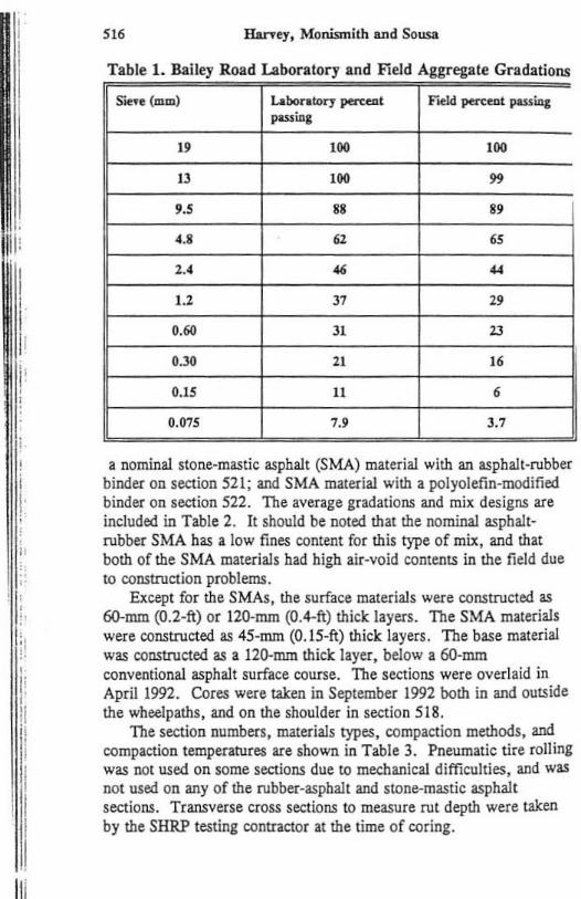
Table 1. Bailey Road Laboratory and Field Aggregate Gradations
S"1t'ft (mm) Labor.wry ~t F"odd ~eat pauia& PLUto,
I' 100 100
13 100 " '.5 .. .. ' .S 61 65
2.4 " " 1.2 J7 " 0." 31 13
O.lO 21 I' O. lS 11 • 0.075 7.' 3.7
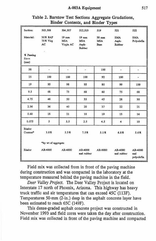
a nominal stone-mastic asphalt (SMA) material with an asphalt-rubber binder on section 521; and SMA material with a polyolefin-modified binder on section 522. The average gradations and mix designs are included in Table 2. It should be Doted that the nominal asphaltrubber SMA has a low fines content for this type of mix, and that both of the SMA materials had high air-void contents in the field due to construction problems.
Except for the SMAs, the surface materials were constructed as 6O-mm (O.2-ft) or 120-mm (O.4-ft) thick layers. The SMA materials were constructed as 45-mm (O.lS-ft) thick layers. The base material was constructed as a 12O-nun thick layer, below a 6O-rrun conventional asphalt surface course. The sections were overlaid in April 1992. Cores were taken in September 1992 both in and outside the wheeipaths, and on the shoulder in section 518.
The section numbers, materials types, compaction methods, and compaction temperatures are shown in Table 3. Pneumatic tire rolling was not used on some sections due to mechanical difficulties, and was not used on any of the rubber-asphalt and stone-mastic asphal t sections. Transverse cross sections to measure rut depth were taken hy the SHRP testing contractor at the time of coring.
A-003A Equipment
Table 2. Barstow Test Sections Aggregate Gradations, Binder Contents and Binder Types •
S<>«iooo: SOl.SOI SOC.S07 ~ 12.5U '" no m
"""""-I: ]01 RAP ,,- ,,- ,,- ,~ ,~
SI7
7(l1 Viq ~, ~, ~ ~,. Poly.1<fiD
" Viqio At; - - ~
~
1 !'aMiD&: S;"vc (mol
" - )00 - -
" )00 )00 )00 " )00 -
" " " " w " )00
.. , .. " .. ~ " " ' .15 .. ~ " " " '" 2.36 " .. " " n " .~ u " JO " U "
0.Q75 , " " .. , • JO
lIit1<1 ...
C""""'· UI ~.ll 7.51 S.lI 6.11 5.61
· by .... of ' URI'"
~" ~- ~-u_ AR·IOCO AA_ u_ ~- ~-, ~
l"'1y<lktm
Field mix was collected from in front of the paving machine during construction and was compacted in the laboratory at the temperature measured behind the paving machine in the field.
Deer Valley Projea. The Deer Valley Project is located On Interstate 17 north of Phoenix, Arizona. This highway has heavy truck traffic and air temperatures that can exceed 4SC (113F). Temperatures SO-mrn (2-in.) deep in the asphalt concrete layer have been estimated to reach 6SC (149F).
This dense-graded asphalt concrete projec.t was constructed in November 1993 and field cores were taken the day after construction. Field mix was collec.ted in front of the paving machine and compacted
51' ~ty, Monismith and Sousa
Table 3. Barstow Test Sections Field Compaction Information
Sec:tioD ColllpactioD ~uipmeGt Breakdo_ TemperatlU"e
SOl V,S,S I72C (2&OFJ
SO. V,s,S IISC (2.4SF)
507 v,r,s U SC (l4SF)
SO, V,P,S 116C (240F)
512 V,s,S IJSC (l75F)
5ll V,S,S U SC (27Sf)
Sl8 V,P,s l2le (250F)
51. v,r,s 121C (250F)
5ll V,5,S uokllown
522 V,S,S UlikDOWlI
Key to Compaction Equipment V vibratory 12.5 ton teel wheel 21,000 Ib peak-la-peak, 2300 rpm S Static 10 ton steel wheel p Pneumatic 15 ton, 110 psi tire pressure
in the laboratory at the fie1d compaction temperature of 149C (300F). Field compaction equipment consisted of two vibratory steel wheel rollers, followed by a static steel wheel roller. The two field test sections contained the same mix but were subjected to two levels of compaction, the difference being the number of passes by the rollers.
The aggregate gradation and binder content are shown in Table 4. One percent by weight of aggregate cement was added to the mix to reduce moisture susceptibility. The binder was a PG70-10 (SHRP classification), including approximately fou r percent polymer modifier.
Test Method. Specimens were tested using the repetitive simple shear test at constant height (RSST·CH) (Sousa et aI. [61, Harvey and Monismith [4], Sousa [7). Although several different repetitive shear stresses were used, only one stress was used for comparison of
A-003A Equipment 5"
Table 4. Deer Valley Project Aggregate Gradation and Binder Content
Sieve (mm) % Passing
9.5 76
4.75 46
2.36 41
0.45 13
0.075 5.2
Binder Content (by wi of agg) 4.2%
Binder PG7()"10 (AC20 W/3% SBS)
specimens and cores from a given section. The repetitive shear stress was 45 kPa (6.5 psi) for the Bailey Road specimens and specimens from section 519 of the Barstow sections, 69 kPa (10 psi) for the Barstow SMA specimens and those from the Deer Valley Project, and 59 kPa (8.5 psi) for al l other tests. The current recommendation is for a 69 kPa (10 psi) shear load to represent critical tire pressures and loads for mix design. Tests for this paper with shear loads other than that recommended were performed previous to the recommendation, and can be considered to represent permanent shear deformation caused by lower tire pressures and loads. They are still useful in evaluating the mix resistance to permanent shear deformation .
The Universal Testing System used for the RSST -CH consists of axial and shear hydraulic actuators, each connected to a head operating on linear bearings inside a temperature chamber and controlled by closed-loop digital software. The specimen is attached with epoxy to platens which are clamped to the head of each actuator. The axial actuator is progranuned to maintain the specimen at a constant height, using an axial linear variable deformation transducer (L VDT) for feedback. The shear actuator applies a repetitive load cycle of O. l-sec haversine load duration followed by a O.599-sec rest period. Shear deformation is measured at progranuned intervals using an LVDT and target attached with epoxy to the side of the specimen.
520 Harvey, Monismi th and Sousa
All of the tests fo r this paper were performed at 60C (140F), except for the Deer Valley Project for which a 65C (149F) test temperature was used.
Pennanent shear deformation measured in the RSST -CH has been estimated using finite element modeling and limited subse{[uent field validation to approximately correlate with rut depth (Sousa et al . [9]), as follows:
Rut depth (mm) = 279 • RSST -CH permanent shear strain. Thus, the 2.0 percent permanent shear strain selected as failure for this paper approximately corresponds to a rut depth of 5.6 mm (0.22 in.) in the field .
Test results for larger permanent shear strains are often extrapolated after 5,00000 10,000 load repetitions. The mean square error of the natural log of the number of load repetitions to a given pennanent shear strain has been estimated to be approximately 0.68 for laboratory specimens with air-void contents within plus or minus 0.5 percent of the target value. Included in the mean square error is variance due to specimen preparation, the air-void content range, test results , and extrapolation. The mean square error has generally been found to be less for test results for which no extrapolation is required and when the specimens are compacted using field mix collected at one location in each section, as was the case for nearly all the test results presented in this paper.
Results and Analysis
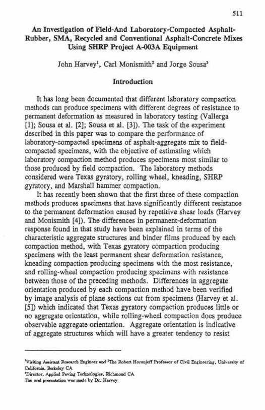
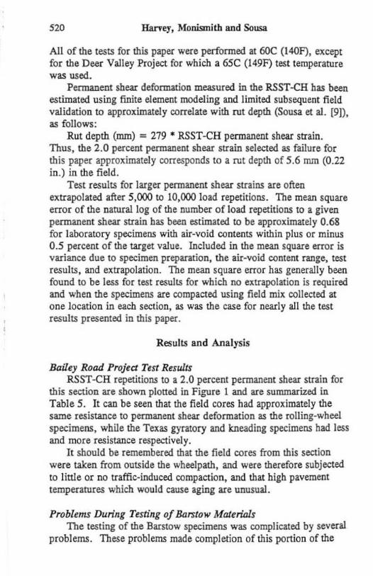
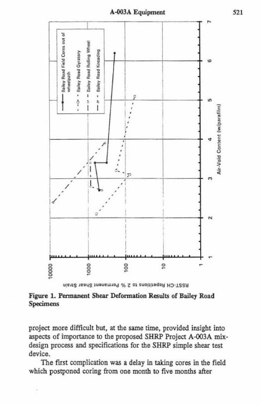
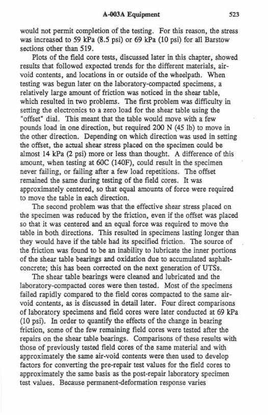
Baaey Road Projea Test ResuUs RSST-CH repetitions to a 2.0 percent permanent shear strain for
this section are shown plotted in Figure 1 and are summarized in Tabl e 5. It can be sun that the field cores had approximately the same resistance to permanent shear deformation as the rolling-wheel specimens, while the Texas gyratory and kneading specimens had less and more resistance respectively.
It should be remembered that the field cores from this section were taken from outside the wheelpath, and were therefore subjected to little or no traffic-induced compactinn. and that high pavement temperatures which would cause aging are unusual.
Problems During Testing of Barstow Materiols The testing of the Barstow specimens was complicated by several
problems. These problems made completion of this portion of the
A-003A Equipment
•
1 ! I i ~ j f ~ r-r-t----t-
l--- +
h i I I I I' ni~i i -t ? ~.. I
I I ! ,: i i ;: !
•
•
1/ J{ C-
. ' I / I. :. ·1;: / ', I. '" . 1 - . .'!
I . . . : 1.(
i , N
8
Figure 1. Permanent Shear Defonnation Results or Bailey Road Specimens
project more difficult but, at the same time, provided insight into aspects of imponance to the proposed SHRP Project A-003A mixdesign process and specifications for the SHRP simple shear test device.
The flrst complication was a delay in taking cores in the field which postponed coring from one month to five months after
521
Harvey. Monismith and Sousa
construction. As a result, the pavement was subjected to five months of extreme Mojave desert surruner temperatures and heavy truck traffic. Once the cores were taken, they were immediately cut to size, tested for air-void content, and tested on the UTS. Unfortunately, scheduling conflicts with other testing programs being carried out on the UTS required that all the field cores be tested before the laboratory compactions were completed. A week later, time was available to test the laboratory-compacted specimens.
A shear stress of 45 kPa (6.5 psi) was initially selected to test the field cores, the same shear stress used for testing the Bailey Road specimens. The tests on the base material from section 519 indicated
Tab le 5. Bailey Road Repetitive Simple Shear Test Results
RSST·CK Rq>ro '" .,..,.. AV ("'P) C~1f>*d> 2': r ...... SlIt Sino
...., """ ,.,..,.~ Sbo&r SItaI # .1
~"" ,,~ ,., - ,.. CC·l ••• - M. CC·] ••• - ". CC·2 .. , - '" = A " T.uo 1Y""''l' ~,
CCG·O U T ..... 0'''''''''' n
,,~ ,., r ..... 0'''"'''''' m
cco·s '-' T __ 0'''"'''''' " CCR.-Al ,., lOuq .. bcd '" CCR.-A2 U ",um, .. bul .~
CCR·M ••• roum, .. bul on
=., u -.. ~" CO:·2 ••• -.. '"
that this stress was low, and that the cores would not fail before 20,000 to 40,000 load repetitions. Tests that required that much time
A-003A Eqwpment 523
would not permit completion of the testing. For this reason, the stress was increased to 59 lcPa (8.5 psi) or 69 kPa (10 psi) for all Barstow sections other than 519.
Plots of the field core tests, discussed later in this chapter, showed results that followed expected trends for the different materials , airvoid contents, and locations in or outside of the wheelpath. When testing was begun later on the laboratory-compacted specimens, a relatively large amount of friction was noticed in the shear table, which resulted in two problems. The fi rst problem was difficulty in setting the electronics to a zero load fo r the shear table using the ·offset" dial . This meant that the table would move with a few pounds load in one direction, but r~uired 200 N (45 lb) to move in the other direction. Depending on which direction was used in setting the offset, the actual shear stress placed on the specimen could be almost 14 kPa (2 psi) more or less than thought. A difference of this amount, when testing at 60C (l40F). could result in the specimen never failing, or failing after a few load repetitions. The offset remained the same during testing of the field cores. It was approximately centered, so that equal amounts of force were required to move the table in each direction.
The seeond problem was that the effective shear stress placed on the specimen was reduced by the frict ion, even if the offset was placed so that it was centered and an equal force was required to move the table in both directions. This resulted in specimens lasting longer than they would bave if the table had its specified friction. The source of the friction was found to be an inability to lubricate the inner portions of the shear table bearings and oxidation due to accumulated asphal tconcrete; this has been corrected on the next generation of UTSs.
The shear table bearings were cleaned and lubricated and the laboralory-compacted cores were then tested. Most of the specimens failed rapidly compared to the field cores compacted to the same airvoid contents, as is discussed in detail later. Four direct comparisons of laboratory specimens and field cores were later conducted at 69 kPa (1 0 psi). In order to quantify the effects of the change in bearing friction, some of the few remaining field cores were tested after the [epair:s on the shear table bearings. Comparisons of these resul ts with those of previously tested field cores of the same material and with approximately the same air-void contents were then used to develop factors for converting the pre-repair test values for the field cores to approximately the same basis as the post-repair laboratory specimen test values. Because permanent-deformation response varies
,,. Harvey, Monismith and Sousa
exponentially with changes in stress, a logarithmic conversion factor, p, was calculated as follows:
p = log (NBEFORE) J log (NAFTER).
where
NBEFORE is the number of repetitions to a 2·percent pennanent shear strain for specimens tested before repairs, and NAFTER is the number of repetitions to a 2-percent permanent shear strain fo r spedmens tested afier repairs.
The average facto r was found to be 1.4. The following equation was used for the conversion:
The experience described above demonstrates the need (or tight specifications for friction in the shear table and axial platen bearings. If different machines do not have the same friction, or the friction does not remain constant on anyone machine, there will be no way of mowing if a material is meeting a specificat ion for a number of repetitions to failure or not.
It is also apparent that a standardized means of measuring the amount of friction in the bearings should be developed. The method should be quick and easy, and should be performed at the beginning of each testing day. The method should also include how to set the offset so that the same amount of force is required to move the platens in both directions, in order to "center" the electronic zero force datum. For implementation of the test machine and methods, these methods will need to be standardized because comparison of "oranges with oranges" will be essential.
Barstow Sections - Test Results of Field Cores The following discussion is based on test results from the
laboratory specimens and on the NAfTER data from the Barstow fi eld cores included in Table 6 and plotted in Figures 2 through 8.
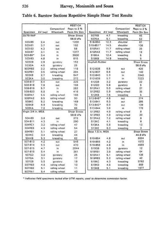
Recycled AspluJit-Concrere, Sections 503 and 508. The air-void contents of the field cores from Section 503 taken from in and outside of the wheelpath show that this section was well compacted and bad little or no densification inside the wheelpath due to traffic. The air-
A-003A Equipment 525
void contents of the field cores from Section 508 indicate that this section was not as well compacted and that there was some densification inside the wheelpaths as evidenced by the lower air-void contents in those cores. It can be seen, for both test sections, that the cores from inside the wbeelpath perlormed better than those from outside the wheelpath, even when the air-void contents are the same. This indicates that, even when traffic does not appear to have caused densification inside the wheelpath, as in Section 503, the repetitive shear forces applied by traffic have resulted in further reorientation of the aggregates, resulting in a stronger aggregate structure. It will be seen that this pattern is repeated in almost every other section, except in Section 519 where the cores were taken from the base layer approximately 90 nun (3 .5 in.) below the surface and were, therefore, not sUbjected to the high shear forces and elevated temperatures present in the surface materials.
It is interesting to note that there appears to be a greater improvement fo r the cores taken from inside the wheelpam versus those taken outside it in Section 503, which did not have pneumatictire roller compaction during construction, than in those from 508 which did, despite there being no densification in Section 503. Pneumatic tire roller compaction is generally considered to be better at creating aggregate orientation than static steel wheel rolling. The data from these sections might indicate that some further orientation which might not have occurred in Section 503 during construction due to the lack of pneumatic t ire rolling was imparted by the traffic that followed construction.
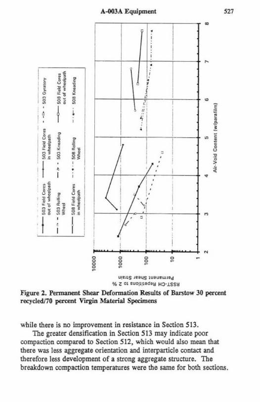
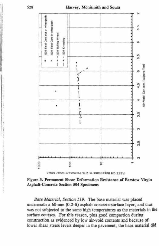
Vjrgin Asphalt-Concrete, Sections 504, 507 and 518. The air-void content and repetitions to fa ilure data indicate that the cores from Section 504 had poorer resistance to shear deformation than did those in Section 507. despite their lower air·void contents. There appears w have been no densification in !he wheelpa!hs of ei!her section. The better performance of the Section 507 cores may be due to the pneumatic t ire roller used during construction of that section, but not on Section 504. The cores from the shoulder Section 518 were very poorly compacted and as a result had little resistance to permanent deformation.
Rubberized Asphalt-Concrete, Sections 512 and 513. The ai r-void content data for these sections indicate that densification occurred inside !he wheelpaths of both. The densification appears to be greater in Section 513. There appears to be a great deal of improvement in the shear deformation resistance inside the wheeJpaths of Section 512,
526 Harvey. Monismith and Sousa
Table 6. Barstow Sections RepetitiTt Simple Shear Test Results
IIssy·eN IISST.(;H c .......... ....., ""P'''~~ ~ .. .;o.v flop. 10 2 -'
$~~ AV!w<>, ~"",h " ...... Shr 5 ...... ,- Av I_ I _r. .. h __ S". lOI10 IlAP s ..... s" ... !iOnl .., -- ..
51 .• kP. ~07K'" ... - " 503·'5 ... ~, ,,~ SI'·8SO 12.3 ._.' " 503·11 " ~, '" 511·15, ' ",5 -" m SO]·1l ., - " s,aAAI 11.7 '~w"'01 " !>O3·" " • 1317 511AA3 11 ,7 <OIO>g .. ,..01 " SOl·.I ' , .. • ,~ 51&1:4 12.' ............ , 503·13 ... • '" 5,.1 le .9
_ •. , 503G' U '1>" ..... '" A •• h .... ~...-. S~ .... S" ... 5030 ... ••• v.ro',,, " 51 .1 "P. 5031\82 " ,011 .. ; ...... 1 '" 512·83' •• M ". 5031181 ... ' ............ , '" 512·131 •• ~, ,~
~ .. U ......... ing '" 512· .. 0 .., • ,~
SOJ·':' ,., - '" "2·831 " • 1111 So.a-I17 ••• - '" 512G8 ., 0.<0''', " 5011'1" >.0 - ". 511GO ,.
0."''''' • 5011·1,1 ., '" m 512~"" ., ,.,0; .... wllo.1 " 5011·820 •• • ... 51211n " ,.u;ng .. - " SOlI""" ., ,oQ;"9 ...... , '" 512K, ,. _. • ~~, .. , .-.0 ....... ~ 513'&'1" •• - '" -, .. , -- '" 513 ... ' ., ~, m ~~. ... ......... -"; " 513· 80:- ... ., '" ~ .. , .. -.~ .. 51HIU U • '" v;.g;~ ~ III. M,. Sh ... $" ••• 51JRaZ ., ,." ... ""'.' •
5 • . ' "P, S1JI!8] ., ,ott0n9 ..... 01 " S()oO·19 U - '" "311..,2 " ,oIIlno ,",,"I • SOO·'" " • ,~ 5131:C ... -- • ~~. ,., ,oiling .. 1'I«l " ~llK. U -- " ~0-A83 ., 'oIIiftcI ...... , " 51J~£ .. ,
~-,
50-1111 " ,~~"",., " II ... 1.5 ;ft. MS. S ..... SU ... ~O'K C " ...... ~ " U .• .,.
~<O " ...... ..,: " 519·85. ••• ., -!001·11l ... - ... ~1,.a55 .. , • 1572 !001 ·1'. ••• - '" 51""5' ... • .UI !001 ·115 .., • ,~ . 51tG8 ••• W._ " SOl·II' •• • '" 5191181 U ,01"'0 ....... " SOlGC " Wa1ot. " S URA l ••• ,oll!>g ..... ho., ". 501G" " g.,.,", " 51 ~1II3 ... 'oiling ... ho.' " 501GB " g ... ,",. " 519KC ., -~~ .,12 !0011113 ••• ,oIIlftg ........ " 51tKO ... -~~ -~M' .. , ,......" ....... " 51.1 ••• -- 1177 SOl""', ••• ,~ .. 1'I«l .,
-, . , ~. 11 ", .., I
A-003A Equipment
'--'---'---'--""T"
I • t
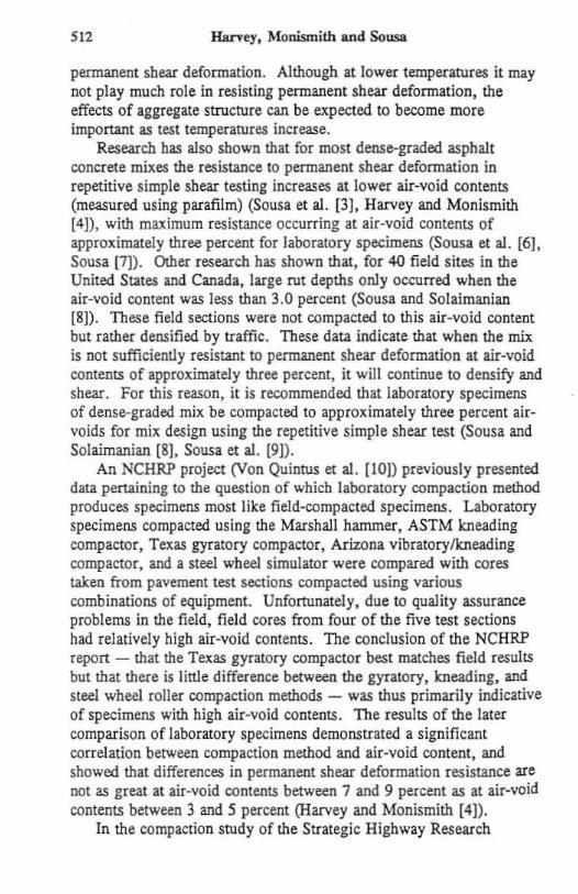
"'~"S ,utlS lUlU_"" '" Z 01 .uO!I!l.~.1I H:>-J.SSll
Figure 2. Permanent Shear Deformation Results or Barstow 30 ptl'cent rec.ycledl70 percent Virgin Material Specimens
while there is no improvement in resistance in Section 513. The greater densification in Section 513 may indicate poor
compaction compared to Section 5 12 , which would also mean that there was less aggregate orientation and interparticle contact and therefore Jess development of a strong aggregate structure. The breakdown compaction temperatures were the same for both sections.
I" ,i! Ii I
I I
I, Ii
52' Hanel. Monismith and Sousa
• .;
•
~ __ i l+!~'~,~~I ____ -+ ,
\ - ·--~ ·--+I·-----+ . I I I
I ' I
I I i • '"
g o
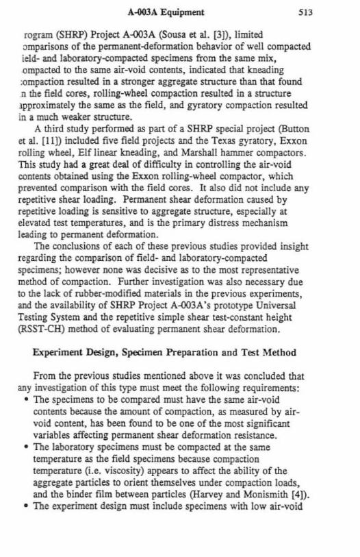
Figure 3. Permanent Shear DeFonnation Resistance or Bantow Virgin Asphal t-Concrete Section 504 Specimens
Base Material, Semon 519. The base material was placed underneath a 6().nun (O.2-ft) aspbalt concrete-surface layer. and thus was oat subjected to the same high temperatures as the materials in the surface courses. For this reason, plus good compaction during construction as evidenced by low air-void contents and because of lower shear stress levels deeper in the pavement, the base material did
/
v 1/
g o
A..003A Equipment
g
o . , '. ,"
o
529
•
•
•
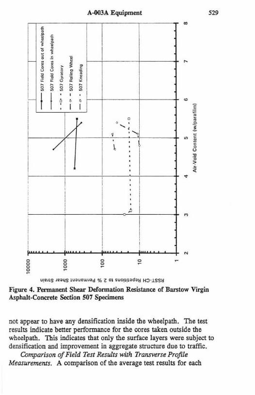
Figure 4. Pennanent Shear Defonnation Resistance of Bantow Virgin Asphalt-Co~te Section 507 Specimens
not appear to have any densification inside the wheelpath. The test results indicate better performance for the cores taken outside the wheelpath. This indicates that only the surface layers were subject to densification and improvement in aggregate structure due to traffic.
Comparison of Field Test Results with Transverse Profile MeasuremeNs. A comparison of the average test results for each
530 Harvey. Monismith and Sousa
<
t f , j • l i ,
• , ! u u • • , • ~ ! , , 0 • " •
o
• N N N N N • • • • •
I I ,
~ · • I I I
i I
I ------,
I •
I ,
~ \
\
I ,
i:
, ~ , • i
0 E • • • u , • ~
••
:1 .. -----, ,
I I , •
I
, I
I , , ,
I •
g o
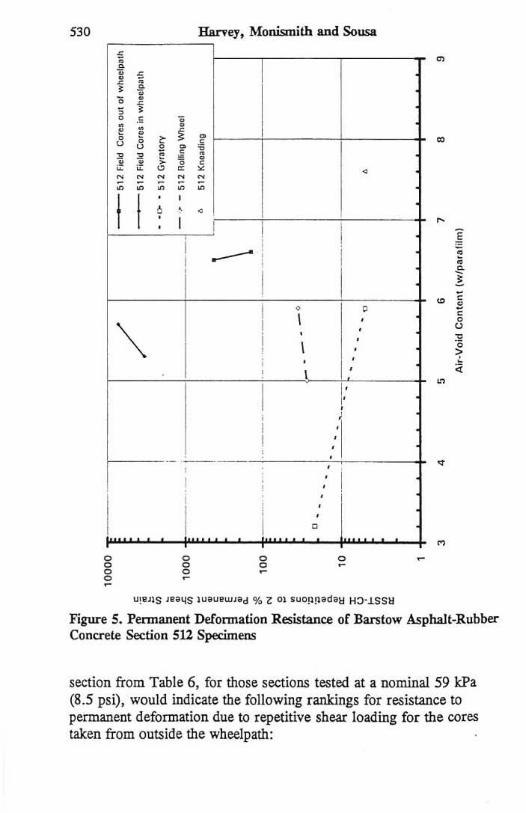
Figure S. Permanent Defonnation Resistance of Bars tow Asphalt~Rubber Concrete Section 512 Specimens
section from Table 6, for those sections tested at a nominal 59 kPa (8.5 psi), would indicate the following rankings for resistance to permanent deformation due to repetitive shear loading for the cores taken from outside the wheelpath:
f • , , I l , i
, , u u
i , ,
0 0 • • \ ·
• , , l: 0
• ; 0 • , 0
• • , , • I I
/ I , ! , "-,-
·
,
i I , ,
o o
A-003A Equipment
I
, , i .
/ . .
~· I / . / I i . , . . ~
\ I', I \ I I ,
o
, . .
o -•
•
~ • ~
o "
o
~ <i
S3l
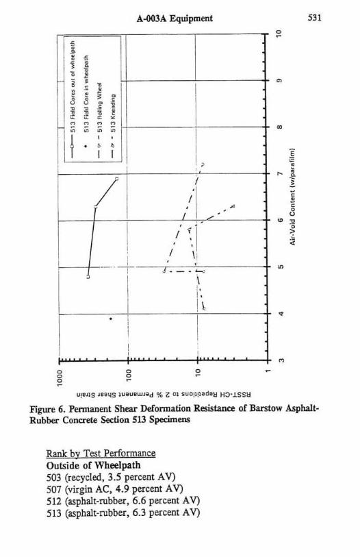
Figure 6. Penn anent Shear Defonnation Resistance of Barstow Asphalt· Rubber Concrete Section 513 Specimens
Rank by Test Perfonnance Outside of Wheelpath 503 (recycled, 3.5 percent A V) 507 (virgin AC, 4.9 percent A V) 512 (asphalt-rubber, 6.6 percent A V) 513 (asphalt-rubber, 6.3 percent A V)
S32 Haney, Monismith and Sousa
•
f i d &
· • .; · • • • • • •
I , • , I I r
• · , , •
i-
i , t ~ , , I
, !
• , ,.; • < I I I I ,
• u
• " • I · ~ , • , .;
I " _. • · · · g g o
o
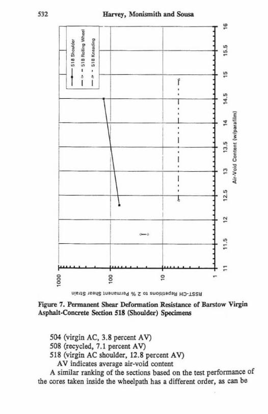
F"agure 7. Permanent Shear Deformation Resistance of Barstow Virgin Asphalt-Concrete Section 518 (Shoulder) Specimens
504 (virgin AC. 3.8 percent A V) 508 (recycled, 7.1 percent A V) 518 (virgin AC shoulder, 12.8 percent AV)
A V indicates average air-void content A similar ranking of the sections based on the test perfonnance of
the cores taken inside the wbeeJpath has a different order, as can be
A.oo3A Equipment 533
• 5
i j , • • , , j l , •
'- • , ! i f 0 0 , > ! ~ ,
0 •
,
• • • • • ! - • • · •
I I ,
! · ~ , • , 1 I
• •
~
1- ' --r---' 0 , !
• , I _. ,
• - 1 I
'\ ·1 ,
i " ...... i· . ' ! ! I
• , • 0 u
• • 0
> .. •
( \ , \
•
i , \ , I
0
I I I
i ,
i i
I • 0
0
g o
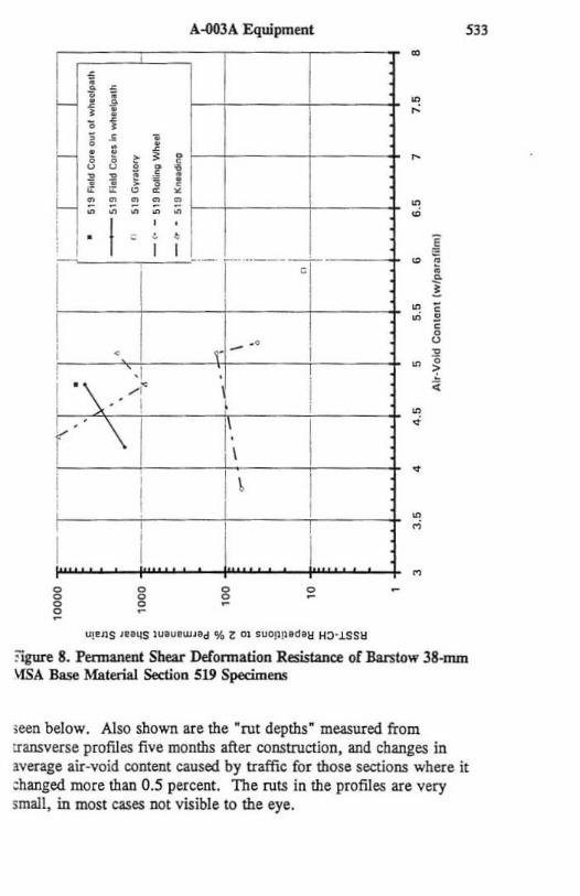
?igure 8. Pennanent Shear Defonnation Resistanc.t of Barstow 38-mm \{SA Base Material Section 519 Specimen!
;een below. Also shown are the "rut depths· measured from transverse profiles five months after construction, and changes in lverage air-void content caused by traffic for those sections where it ;hanged more than 0.5 percent. The ruts in the profiles are very small, in most cases not visible to the eye.
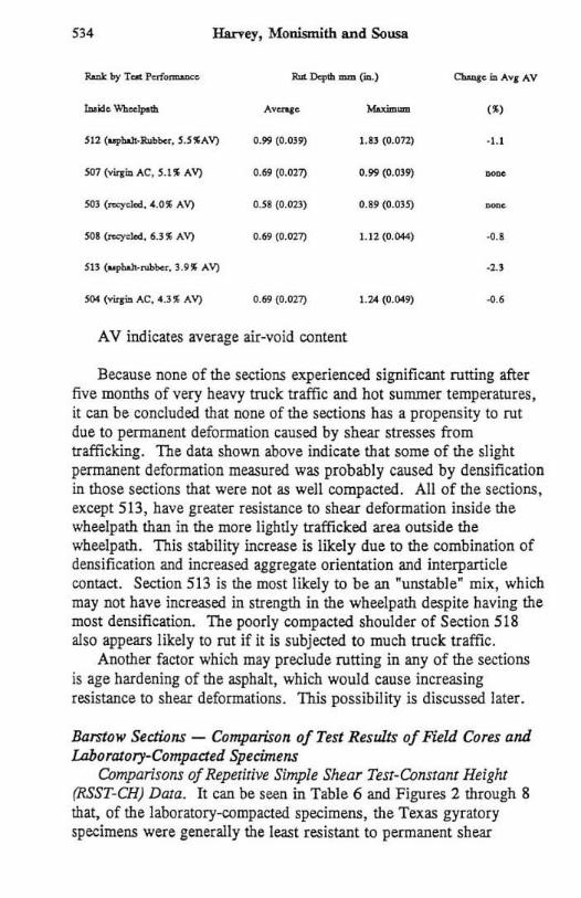
534 Harvey, Monismith and Sousa
........ e Mn'- ,'>
0.99 (0.039) UJ (~.O1l) . !.l
0.69 (O.ln1) 0.99 ({),Om -SOl (=yclod. 4.01 AV) D.n (0.023) 0.19 (O.OJ5) -SOl (=yokd, ~. '" "V) 0.69 (0.02-7) 1.12(0.044) ••
so. (~""" AC. 4.3" Ay) 0.6\1 (O.OZ7) 1.204 (0.0019) •• A V indicates average air-void content
Because none of the sections experienced significant cutting after five months of very heavy truck traffic and hot sununer temperatures, it can be concluded that none of the sections has a propensity to rut due to permanent deformation caused by shear stresses from trafficking. The data shown above indicate that some of the slight permanent deformation measured was probably caused by densification in those sections that were not as well compacted. All of the sections, except 513, have greater resistance to shear deformation inside the wh~lpath than in the more lightly trafficked area outside the wbeeJpath. This stability increase is likely due to the combination of densification and increased aggregate orientation and interpanicle contact. Section 513 is the most l ikely to be an ftunstableft mix, which may not have increased in strength in the wheelpath despite having the most densification. The poorly compacted shoulder of Section 518 also appears likely to rut if it is subjected to much truck traffic.
Another factor which may preclude rutting in any of the sections is age hardening of the asphalt, which would cause increasing resistance to shear deformations . This possibil ity is discussed later.
Barstow Sections - Comparison of Test Results of Field Cons and LabOralory-Compaded Specimens
Comparisons oj Repetitive Simple Shear Test-Constant Height (RSSr-CH) Data. It can be seen in Table 6 and F igures 2 through 8 that, of the laboratory-compacted specimens, the Texas gyratory specimens were generally the least resistant to permanent shear
A-003A Equipment
deformation caused by repeated shear loads, followed by rOlling-wheel and kneading specimens. It can be seen in the plots that Texas gyratory specimens only performed better than rolling-wheel and/or kneading specimens if they bad considerably lower air-void contents. In a few cases, 1cneading specimens had permanent shear deformation resistance below that of the rolling-wheel specimens. However, in those sections the air-void contents were fairly high , indicating little compaction and the lack of a distinctive compaction-induced aggregate structure.
Comparison of RSST -CH data from the field cores (NAFTER, adjusted as discussed previously) and the same materials compacted in the laboratory using Texas gyratory, rolling wheel, and kneading compaction, demonstrates that for all sections the field cores had considerably more resistance to permanent shear defomation than did any of the laboratory specimens. This result is consistent for every section, except Sections 503 (30nO recycled material) and 519 (base material), where the performance of the kneading compaction specimens was approximately that of the field cores from inside the wheelpath. The material from Section 519 was below a 50·nun (2-in.) surface course and therefore was subjected to much Jess heat and air circulation and therefore probably did not age as much as the surface courses. The partially recycled material taken from outside the wheelpath of Section 503 contained only 3.S percent virgin asphalt (by weight of aggregate) which probably reduced the effect of aging, and was not compacted with the pneumatic tire roller, whicb might have reduced the development of an improved aggregate structure. The same material taken from outside the wheelpath in Section 50S, but compacted with the pneumatic tire roller, performed bener than the kneading compaction specimen.
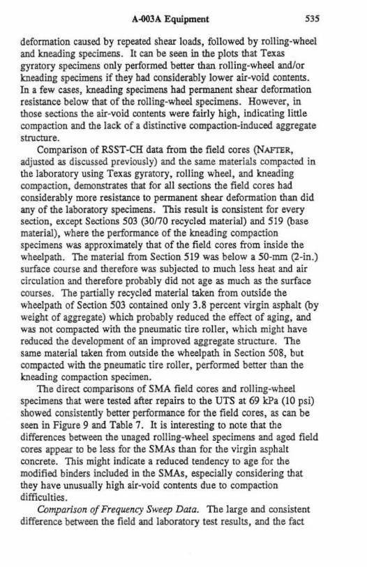
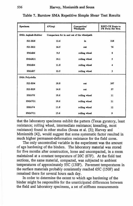
The direct comparisons of SMA field cores and rOlling-wheel specimens that wefe tested after repairs to the UTS at 69 kPa (10 psi) showed consistently better performance for the field cores, as can be seen in Figure 9 and Table 7. It is interesting to note that the differences betWeen the unaged rolling-wheel specimens and aged field cores appear to be Jess fat the SMAs than for the virgin asphalt concrete. This might indicate a reduced tendency to age for the modified binders included in the SMAs, especially considering that they have unusually high air-void contents due to compaction difficulties.
Comparison oj Frequency Sweep Data. The large and consistent difference betWeen the field and laboratory test results, and the fact
536 Haney, Morusmith and Sousa
Table 7. Barstow SMA Repetitive Simple Shear Test Results ,- -,V(.,) c_ ..... ;. ... .,... ..... 1tSST.cD a.pr..o Lo l .... _SUsu.
SMA .......... _R-.. c-,...-,..,. _ aM _.t ... _pod
n t·1lI ,u • '" nl·IU ".5 - " ""'" u
_ ..... • """" ,1.1
_ ..... , ~. II.'
_ ..... •
~, 120$ .......... , SMA hl)"oIcft,a
~~ 10.' - '" 511-12' 14.1 - n
S~Yf IU _ .....
" """" 1 •• ' .. Ilioc_ " "'-<" '"
_ ..... "
SM.o\VIl ". nGiq """'" ,
that the laboratory specimens exhibit the pattern (Texas gyratory, least resistance; rolling wheel, intermediate resistance; kneading, most resistance) found in other studies (Sousa et al. (3); Harvey and . Monismith (4)), would suggest that some systematic factor resulted in much higher permanent-deformation resistance for the field cores.
The only uncontrolled variable in the experiment was the amount of age hardening of the binders. The laboratory material was stored fo r five months after construction, loose and uncompacted, in a room maintained at a constant temperature of 20C (67F). At the field test sections, the same material, compacted, was subjected to ambient temperatures of approximately 55C (lJOF). Pavement temperatures in the surface materials probably consistently reached 65C (150F) and remained there fo r several hours each day.
In order to detennine the extent to which age hardening of the binder might be responsible for the unanticipated differences between the field and laboratory specimens. a set of stiffness measurements
i -' ,.
I
A.ooJA Equipment
.
! I i· r
. j I /
/ , , 1
, I I , , I l- I I
I I I , 1/ I
I 1
",I J}S ,nIlS ' ........... '.d '" Z 01 .uO!1~.d~ to-.LSSII
•
•
•
o
•
Ftgun 9. Permanent Shear Defonnation Resistance or Barstow SMA Asphal t-Rubba- (Section 521) and SMA Polyolef"UI (Section 522) Specimens
S37
were made on a pair of comparable specimens, one from the field and one from the laboratory. The specimens were from Section 504 (virgin asphalt concrete) and had similar air-void COntents. To measure the stiffness of the binders in the specimens, and to minimize the contribution of the aggregate strucrure, the specimens were tested at 20C (68F) at a shear strain of 0.0001. Previous research (Sousa et aI. (9]) has shown that at this strain level damage to the response of
'38 Raney, MonisrDitb and Sousa
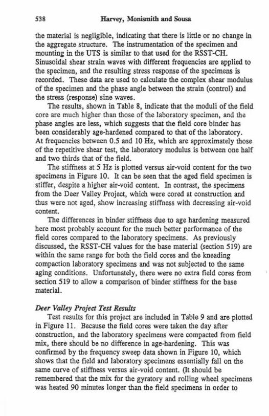
the material is negligible, indicating that there is little or no change in the aggregate structure. The instrumentation of the specimen and mounting in the UTS is similar to that used for the RSST -CR. Sinusoidal shear strain waves with different frequencies are applied to the specimen, and the resulting stress response of the specimens is recorded. These data are used. to calculate the complex shear modulus of the specimen and the phase angle between the strain (control) and the stress (response) sine waves.
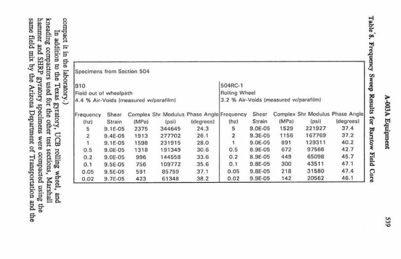
The results, shown in Table 8, indicate that the moduli of the field core are much higher than those of the laboratory spedmen, and the phase angles are less , which suggests that the field core binder has been considerably age-hardened compared to that of the laboratory. At frequencies between 0.5 and 10 Hz, which are approximately those of the repetitive shear test, the laboratory modulus is between one balf and two thirds that of the field.
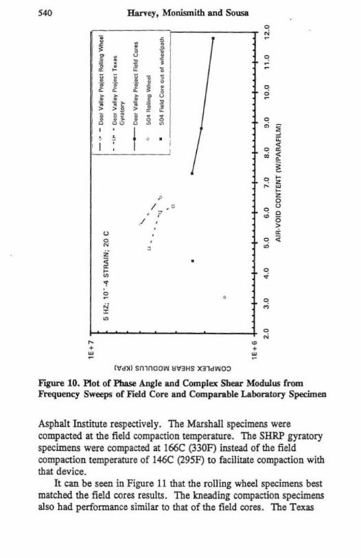
The stiffness at 5 Hz is ploned versus air-void content for the two specimens in Figure 10. It can be seen that the aged field specimen is stiffer, despite a higher air-void content. In contrast, the specimens from the Deer Valley Project, which were cored at construction and thus were not aged, show increasing stiffness with decreasing air-void content .
The differences in binder stiffness due to age hardening measured here most probably account for the much bener performance of the field cores compared to the laboratory specimens. As previously discussed, the RSST-CH values fo r the base material (section 519) are within the same range for both the field cores and the kneading compaction laboratory specimens and was not subjected to the same aging conditions. Unfonunate[y, there were no extra field cores from section 519 to allow a comparison of binder stiffness for the base material.
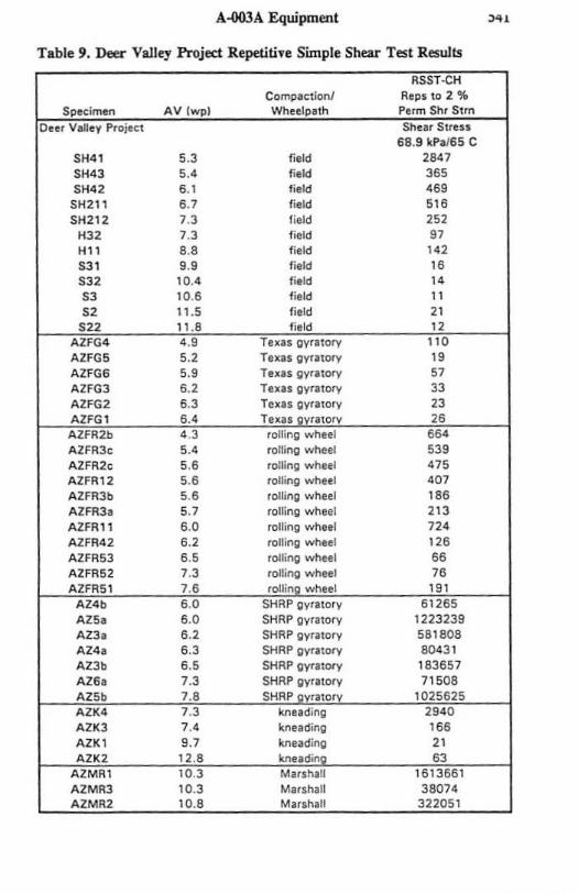
De~r Valley Pl'Ojed Test Results Test results for this project are included in Table 9 and are ploned
in Figure 11 . Because the field cores were uken the day after construction, and the laboratory specimens were compacted from field mix, there should be no difference in age-bardening. This was conflflJled by the frequency sweep data shown in Figure 10, which shows that the field and laboratory specimens essentially fallon the same curve of stiffness versus air-void content. Qt should be remembered that the mix for the gyratory and rolling wheel. specimens was heated 90 minutes longer than the field specimens in order to
. ~ ~ ~ i ~ ::tl f1I 8; S' 'g 5:~Jil ~!l 88.8~::;· ~'Vl35'5'
~~ ~ & ~~~~::~::~::~-----------------------------------------------~i'g~8f11 fi"1:! ~ fi"~ ~;1g"lJ !r.~ B. ~ 8 ::I 0' l: .:!
SpCtcimcns Irom SlIctlon 504
504RC·\ RoI~ng Wheel
010 Fluid oul 0 1 wh(lolpath
~~s.~'-' .g~§.~S
" !T'l a "• "C a~ii () s,;;;;~ ", 8Sg, el .g c' S' ~l>Jt:lCJCI '8 !l ,In 1:! il!l.;::~ ~ • • c:: e: [ o • -::;! S' ::r '" '" CJCI e ::I a!T-p.
!T"
"
4 .4 % Alr.Voids (measured wfptnalilrn'
IFraqucncy Sheaf Complo_ Sh, Modulus Phase AnDie
(hzl Strain (MPal (psil [de9rcll s l , 9.1£-05 2375 344645 24.3 2 9.4E·05 1913 217702 26. 1
9. I E·05 1598 2310 15 28.0
0.' 9 .0e·05 13 '8 191349 30.6 02 9.0E·05 996 144558 33.6 O. , 9.5E·05 756 109772 35.6
0.05 9.5E·05 '" B5159 31.1 0.02 9.1E·05 '" 61348 38.2
3.2 % Alr.Vold$ (mo;uured w/paillfilm)
Frequency Shcer CQmple_ Siu Modulus PhaSlt Angle:
thzl Slraln (MPa) (psi) [degrces) , 9.0E·05 1529 221927 37.4
2 9 .3E-05 1156 '61769 37.2 , 9.0E-05 ." '29311 40.2
0.' B.9E-05 672 97566 42.7
0.2 8.9E·05 '" 65098 45.7 O. , 9.BE·05 300 43511 47.1
0.05 9.BE·05 ". 315BO 41.4 0.02 9.9E·05 '" 20562 46.1
.. • i1' ,. { ~
~ , R ~
[ > §
~ > 0' '" ,
D
r E. ~
3
" [ , " "-~ n 0 ;/
i:l ~
540 Haeny. Monismith and Sousa 0
'" • f ~ ~
f ! 0
I
, ~ , ;
-¥ ·i 1 ! j , , ! 0
i i i i f ci
! > >
i ~ , .
! • • . , • 0 00
0 • , ) I " , " , [ <
0 • • <
~ 0 " z " w
" , z 0
I . ' 0 0
· , • 0
./ " > 0 " 0 0 • N • ii
, • • 0 " • .; , • • 0
'" M Z
• 0
'" " • • • w w . {"dXI smnaow II1RHS )(3101'010:>
r'iUN 10. Plot of Phase Angle and Complex Shear Modulus from Frequency Sweeps of Fidd Core and Comparable Laboratory Specimen
Asphalt Institute respectively. The Marsha11 specimens were compacted at the field compaction temperature. The SHRP gyratory specimens were compacted at 166C (330F) instead of the field compaction temperature of 146C (295F) to facilitate compaction with that device.
It can be seen in Figure 11 that the rolling wheel specimens best matched the field cores results. The kneading compaction specimens also had performance similar to that of the field cores. The Texas
A-OOJA Equipment ,.. Table 9. Deer VaIley Project Repetitive Simple. Sheu Test Results
CompaClion! Re ps 10 I 'lII
, 68.9 kP, /65 C
SH41 5 .3 f,eld 1847 SH43 5 .' field 365 SH42 6 .' field "9 SHll I 6 .7 field 5" SHIl l 7.3 field 252
H32 7.3 fie ld 97 H" 8.8 fie ld '" SJ ' 9.9 field " SJ2 10.4 ffeld " SJ 10.6 f;'ld " 52 11 .5 field " ; ,
gyra lory AIFG5 5.' Texu gyrl lOt"'f " AIFG6 5.9 Tun gyrllOt"'f " AZFG3 6.' Tun gyrllOlY 33 AlfGI 6 .3 TexIS gyr'lcry 23
IIi
AIFR3c 5.' rolli ng wheel 5" AIFRlc 5.6 roning w heel '" AIFR12 5.6 roll;"g wheel ' 0 7 Al f R3b 5.8 rolling w hul "6 AIFR3, 5.7 rclling w heel '" AIFRll 6.0 rclling w heel 7" A2FR42 6.' rcll ing wheel " 6 AZFRS3 6 .5 rolling wheel 66 AIFRS2 7 3 romng wheel 76
AZS, 6 .0 SHRP gyriltory 1223239 A13, 6 .' SHRP gyratOry 58 1808 A14, 6 .3 SHRP gyrllOlY 80431 AZ3b 6 .5 SHRP gyrllOlY 163651 Al6a 7.3 SHRP gyratory 71508
kneading AZK3 7. ' kneading "6 AZKl 9.7 knuding "
" " "
Ha.r-rey. Monismitb IIId SoILU
; • i S ; ~ ~ • 0 i ! ; f • 1 • , • , • • •
•
J J , , i I t "
< < < • • ! f f h ! ! . > > , • ~ ~ ! ! , • ,
I , , ,
1 ': < ! , , , , I I , I ,
I ' ~ , , ---_ ..... ,
, 12-1, I I:'
, - I i I -1- . . i . or I
" , ;::
• .. !
• , • , , 0
• , ~
1 ~,'1 I , .' . ,
I .' - , r 'T ! f ' t. , . .
I I I . , ~ ,
I I II ,
1 , I
,
•
g g o
o
o g
",_JlS ,n45 IUIU'W"d '!I. Z OJ SUO!JIJldI1:l HO·.1S S11
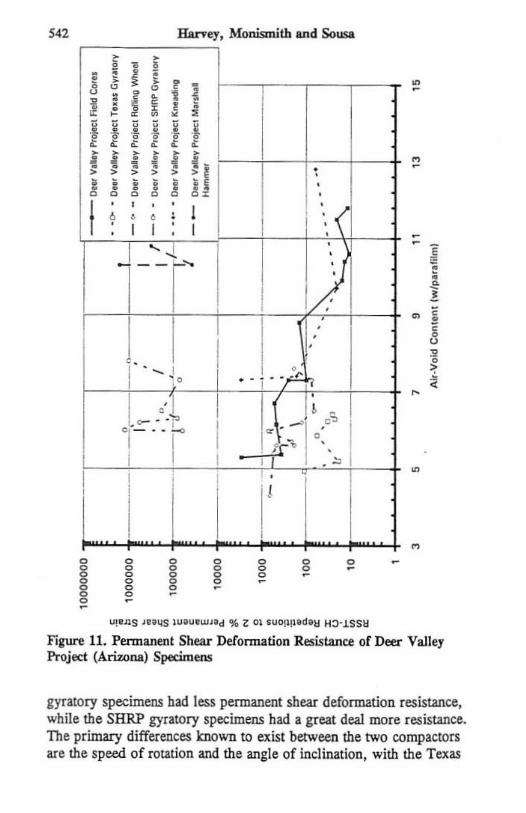
Figure 11. Permanent Shear Defonnation Resistance of Deer Valley Project (ArUana) Specimens
gyratory specimens had less permanent shear deformation resistance. while the SHRP gyratory specimens had a great de.a1 more resistance. The primary differences known to exist between the two compactors are the speed of rotation and the angle of inclination, with the Texas
A-003A Equipment 543
gyratory baving a slower rotation and larger angle. The axial stresses imposed during compaction may also be different. The interaction of these variables is not knOWD. The Marshall hammer could not achieve the air-void contents obtained in the field no matter the number of blows and, even at the minimum air-void content achieved, had much higher permanent shear deformation resistance than the field cores. This result is due to the hammer driving the aggregates together with little or no orientation.
Summary and Conclusions
The original design for the experiment assumed that the test results from field-compacted cores would fall within a relatively narrow range, with respect to the three laboratory compaction methods included in this project. The design also assumed that age-hardening effects on the binder would not significantly affect permanent shear deformation resistance within five months after construction. The first conclusion that must be drawn is that there are other important variables besides laboratory compaction method that must be considered when trying to prepare laboratory specimens that wi1\ perform similarly to those taken from the field.
In particular, those variahles that should be considered of primary importance are:
• Long-term age hardening of the binder. The Barstow virgin asphalt-concrete doubled the stiffness of the hinder within fi ve months after construction. This conclusion is supported by comparative frequency sweeps of field cores and laboratorycompacted specimens, tested at temperarures and strains that virtually eliminate the effects of the aggregate on the stiffness measurements . It is also supported by the test results for the field cores taken from the base material of Section 519, which were not SUbjected to the same elevated temperatures as the surface course materials, and were within the range of the laboratory kneading compaction specimens compacted to the same air-void contents .
Also, all of the surface course field cores had considerably more pennanent-deformation resistance than the laboratory specimens indicating age hardening, except Sections 503 and 508 which contained 30 percent recycled materials and had very low virgin asphalt contents. It has been shown that long-term age hardening (that occurring after construction) can be duplicated in the laboratory by
544 Harre1. Monismith and Sousa
using oven heating of compacted specimens (Bell [12]). Determining a relationship between oven aging and various climates is vital.
• A large increase in resistance to permanent shear defonnation can occur inside the wheelpatbs due to densification and probably in combination with funher aggregate orientation and interpanicle contact. Information presented in this paper indicates that the number of repetitions to failure was higher for cores taken inside the wbeelpatbs compared to those taken outside the wheelpams, for all surface sections but one, including those sections in which no measurable densificalion occurred . No improvement was shown in the section from which base material cores were tested, indicating that the strengthening occurs with elevated temperarures and high stresses near the surface of the pavement. This infonnation suggests that for most dense-graded mixes compaction to air-void contents as close to approximate1y 3.0 percent (measured using parafilm) as possible will result in increased permanent shear deformation resistance. It also suggests that compaction equipment that increases densification. aggregate orientation, and interparticle contact, as might pneumatic-tire rollers, would also tend to increase permanent shear deformation resistance.
The conclusion drawn from previous studies - that, of the three laboratory compaction methods, Texas gyratory compaction produces aggregate structures with the least resistance to permanent shear deformation under repetitive shear loads, kneading compaction produces aggregate structures with the most resistance, and rollingwheel compaction produces aggregate structures with resistance between that of those produced by gyratory and kneading compaction - was confirmed herein. F ive mixes were tested fo r comparison between field cores and laboratory-compacted specimens that had the least hardening of the binder caused by environmentaJ conditions.
These results showed that: • For one dense-graded asphalt-rubber section (Bailey Road), not
subjected to high temperatures. the field cores taken from inside the wheelpath on a relatively lightly trafficked pavement had load repetitions to failure between those of rolling-wheel compaction and Texas gyratory compaction,
• For one section (Barstow Section 519) with virgin asphalt and 38-mm (1.5-in.) maximum aggregate size base material, which was
A-003A Equipment "5
sUbjected to somewhat elevated temperatures for five months, the base course field cores performed approximately the same as the kneading compaction specimens.
• For two sections (Barstow Sections 503 and 508) with 30 percent recycled asphalt-concrete, 70 percent new aggregate, and a low virgin asphalt-content but subjected to higb temperatures, the kneading and rolling-wheel values were similar to those of the field cores.
• For one section (Deer Valley Project) with dense-graded asphalt concrete and no age-hardening the rolling wheel and kneading specimens had permanent shear deformation resistance similar to that of the field cores, while the Texas gyratory specimens had less resistance. The SHRP gyratory specimens had a great deal more resistance than the field cores, as did the Marshall hammer specimens despite their high air-void contents.
The conclusioru suggested by the information presented above regarding the comparison of fi eld- and laboratory-compacted cores are that:
• Texas gyratory-compacted specimens always had less resistance to permanent shear deformation than the field cores;
• Rolling-wheel compaction specimens had somewhat more, somewhat less, or similar resistance to permanent shear deformation compared to field cores which were not subjected to much age hardening or traffick.ing, and less resistance than field cores which were subjected to extreme age h ardening and traffic conditions;
• Kneading compaction specimens had more permanent shear deformation resistance than cores which were not subjected to age hardening or trafficking, had approximately the same resistance as cores subjected to some age hardening and trafficking, and had less resistance than cores subjected to considerable age hardening and trafficking;
• SHRP gyratory-compacted specimens had much more resistance than cores not subjected to trafficking or aging.
The lessons learned about the UTS during execution of this experiment lead to the conclusion that, since it will be required that a machine provide valid comparisons of mixes tested at different times, or on different machines, specifications must be adhered to in the design and production of the machine so that the friction in the
546 Haney. Monismith and Sousa
bearings and the performance of other components remain stable, can be maintained , and can be easily measured to determine if the machine is within specifications. This will be especially important during production of mix designs, where highway agencies will be comparing test resu1ts to specified perfonnance guidelines which will be based on use of machines that produce equivalent results. The prototype UTS used for mis project bas performed well and allowed the evaluation of non-conventional materials, such as asphal t-rubber and stone-mastic asphalt mixes, using greatly improved testing methods that capture the most critical mechanisms affecting flexible pavement permanentdeformation perfonnance.
It is recommended that further research be carried out to determine the process by which asphal t-aggregate mixes densify and accumulate pennanent shear deformation, while increasing their resistance to the same, due to further aggregate orientation and age hardening of the binder. This research should include additional validation of the SHRP repetitive shear test (RSST -CH) with field measurements of permanent shear deformation at various stages of age hardening and densification, and moisture damage when appl icable.
Acknowledgments
The research reported herein was partially supported by Project A-003A of the Strategic Highway Research Program (SHRP). That project, entitled "Performance Related Testing and Measuring of Asphalt-Aggregate Interactions and Mixtures." was conducted by the Institute of Transportation Studies at the University of California. Berkeley. SHRP was a unit of the National Research Council that was authorized by Section 128 of the Surface Transportation and Uniform Relocation Assistance Act of 1987.
Financial suppOrt was provided for two years by the U.S. Department of Transpon.ation through the University of California at Berkeley Transpon.ation Center. Thanks are due to the California Department of Transportation TransLab and District 8 laboratories and Jack van Kirk and Joe Hannon. the Ariz.ona Department of Transpon.ation and George Way, and the Contra Costa County Department of Public Works and Steve Buckman for assistance in obtaining field cores and mix . Thanks are also due to Rita Leahy (SHRP). Nichols Consulting Engineers. Steve Wil ey (CaJtrans) , Anne Stonex (International Surfacing Inc.), the Asphalt Institute and FHWA. The help of Dr. Akhtar Tayebali, Ms . Margaret Paul , Mr.
A-003A Equipment
Ed Nicks, and the UCB laboratory technicians is gratefully acknowledged.
Disclaimer
5"
This paper represents the views of the authors only and is not necessarily reflective of the views of the National Research Council, SHRP. or SHRP's sponsor. The results reponed here are not necessarily in agreement with the results of other SHRP research activities. They are reported to stimulate review and discussion within the research community.
References
1. B. Vallerp, (19S1). 'Recent LaboJratory Compadion Studies o f Bituminou. Paving Mixturc. , ' PrwcedioC!' The AuocWion of AJphah Pavin, TechnologUt$, Volume 20 , pp. 117-153.
2. 1. Sousa, 1. Deacon, and C. L. Monismith (199la). -Effects o f Laboratory Compaction Method on Permtnent Deformation ChuaeterUticl of Asphalt Conerete Moo-urcs,' J>mceediogs, The Association of Asphalt Paving Technologists. Volume 60, pp 533-565,
3. 1. Sousa. 1. Harve),. L. PlintU . 1. Deacon and C, L. Monismith (1991b). "Evaluation of Uboratory Proec.durcs fo r Compaetinc Al:phah-A&&uglte: Mixtures". SHRP TecluUea1 Memorandum No. TM-UCB-A-OOOA-90-S, Univcrsily of California, Berkeley, July.
4. J. Harvey, and C. L. Monismith (1993). -Etrccu of Laboratory Aspb< Concrete Spec:imcn Preparation Vario.bJcs on Fatigue and Pcrmtnent Deformation Test Results Uling SHRP-A-003A TC5ting Equipment,' Presented II the 1993 Transportation Rl:.lean:h Board Annual Mec:ting.
S. J . Harve)" K. Er:ilaen. I . Sousa and C. L. Monumith (1993). -Effects of Laboratory Spec:imen Preparation on Auugatc-Asphalt Structure, Air-Void Content Measurement, and SHRP A-OOJA Repeated Shar Test ResulU, ' Submitted for presentation at the 1994 TrlnlpolUtion Re.search Board Annual. Mcc:ting.
6, J. SoUJ4, J., A. Ta),ebati, J. Harve)" P. Hcndrieb and C. L. Monumith (19931). 'Senlitivity aC SHRP A-003A Teatin , Equipmen( 10 Mix Oeaien Paramct.tnl for Pcrmanen( Deformation and Fatigue," 1'rc$ented at the 11193 Transpottation Relun:h Board Annual Meetin"
7. 1. Sousa, (1994). "Asphalt-Aggregl (e Mix OCl ign Ulin, the Cons(Ult Height Repetitive Simple Shur Tu(," F're5ented at the 1994 Transportation Reaearch Board Annual Meeting.
I. 1. Sousa, and M. SolainwUan (1994). - .... brid,ed Proecdure to Dctcnninc Permanan Dc;Corma.tion of Asphalt Concrcu Pavements. - Presented at the 1"4 Tnruportation Research Board Annual. Meeting.
9. I , Sousa, U al. (1993e). "Permtnent Deformation Rcaponse of AsphaltAggregate: Mixes," Final Report preparod for Stntc&ie Highway Research
·,
548 lhney, Monismith and Sousa
Prognm, Project A-003A. National Rcsun:b Council, WashingtOn, D.C. 10. H.L. Von QUintlll , 1. A. Scl!croc:m&./l, C. S. Hu,h" and T. W. Kennedy (1991) .
• Alphah-Aggregllc Mixture Anl.lysiJ Sy.tern, AAMAS", National Cooperative Hi'h .... y RClcarch Proeram Report 33&, TtanJporution RCIUl'Ch Board, W .. hinpm, D.C., Marth.
11 . 1. Buaon, O. Littk , v. J.pdam and O. Pend1cton (1992). 'Condltion ot Sd«:tcd uboratory COm .... etion Method. with Field COm .... dion·, ~red by the Te:us Transportation lMUtute for the Stn.tca:ie High ..... y Rcsc.arcb Protmn. National RCle.o.rch Council, Project A.ooS, CoUCiC Station, TC~I . May.
12. C.A. Bill, A. Wieder Ind M. Fellin (1993). "Labontory Allin, of Alphalt Aurcgatc Mixtures: Field Valid&tion, ' SHRP T«hnical Memorandum TMOSU·A-OOJA-92-23 , O~,on State Univcnity, Corvallis, Febn.o.ry.
13. M . Solaimanian, and T . Kennedy (1993) . "Prroictin, Maximum Pavement Temperature Ulin, Maximum AU Tempen.1ul'I:' IJId Hourly Solar Radiation,' i';qQ\IM It the 1993 Tnl1lporution Ruearch Board Annll.l.\ Mcctina:.
14 . J, Sousa, S. Wels lman, 1. Sickman and C. L. MOllumith (l993b). "Nonlinur Elutic ViscoUI with Dlm're Model to Pre.dict Permanent Deformltion os Alphalr. Concrete Mix«: Tr&nsportation Resc.lrch Record No. 1384, Tr&nsportltion Research Board, WlshinltOn, D.C.
Discussions
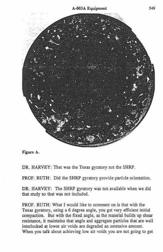
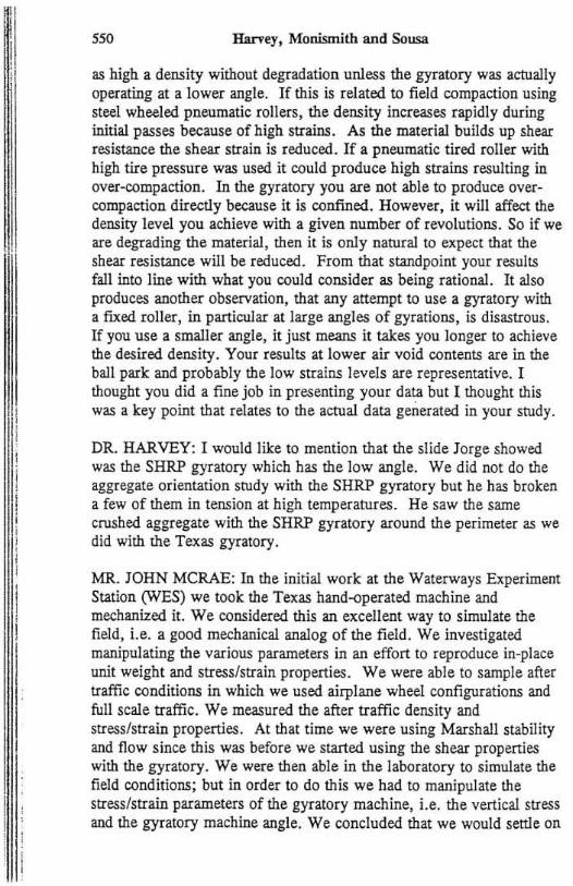
DR. JORGE SOUSA: Figure A. shows the effect of the gyratory compaction to help understand why there is such increased resistance. This is a picture of a specimen compacted in the gyratory. In this case the specimen was compacted with the Texas gyratory and it was pulled apart intentionally. An annular pattern can be seen around the specimen where the aggregate bas been crushed. This is exactly the same thing we just observed with the SHRP gyratory, from cores fabricated from the Arizona project. What appears to be happening is that with 220 gyrations that are required for compaction the aspbalt films get extremely thin and high pressures stan crushing the aggregate around. I think it is very imponant to try to understand the mechanism in case one wants to correct this by reducing the number of gyrations and/or increasing of the angle of gyration.
MR. JOHN HARVEY: Thank: you, Jorge.
PROFESSOR BYRON RUTH: The key to interpretation of your test results is to look: at the entire picture which includes the shear resistance loss that you demonstrate in your paper. I think: you also make reference to the fact that the gyratory really does not orient particles. Is that correct1
A-003A Equipment 549
Figure A.
DR. HARVEY: That was the Texas gyratory not the SHRP.
PROF. RUTH: Did the SHRP gyratory provide particle orientation.
DR. HARVEY: The SHRP gyratory was not available when we did that study so that was not included .
PROF. RUTH : What I would like to comment on is that with the Texas gyratory, using a 6 degree angle, you get very efficient initial compaction. But with the fixed angle, as the material builds up shear resistance, it maintains that angle and aggregate particles that are well interlocked at lower air voids are degraded an extensive amount. When you talk about achieving low air voids you are not going to get
550 Harvey, Monismith and Sousa
as high a density without degradation unless the gyratory was actually operating at a lower angle. If this is related to field compaction using steel wheeled pneumatic rollers, the density increases rapidly during initial passes because of high strains. As the material builds up shear resistance the shear strain is reduced. If a pneumatic tired roller with high tire pressure was used it could produce high strains resulting in over-compaction. In the gyratory you are not able to produce overcompaction directly because it is confined. However, it will affect the density level you achieve with a given number of revolutions. So if we are degrading the material. then it is only natural to expect that the shear resistance will be reduced. From that standpoint your results fall into line with what you could consider as being rational. It also produces another observation, that any attempt to use a gyratory with a fixed roller, in particular at large angles of gyrations, is disastrous. If you use a smaller angle, it just means it takes you longer to achieve the desired density. Your results at lower air void contents are in the ball park and probably the low strains levels are representative. I thought you did a fine job in presenting your data but I thought this was a key point that relates to the actual data generated in your study.
DR. HARVEY: I would like to mention that the slide Jorge showed was the SHRP gyratory which has the low angle. We did not do the aggregate orientation study with the SHRP gyratory but he has broken a few of them in tension at high temperatures. He saw the same crushed aggregate with the SHRP gyratory around the perimeter as we did with the Texas gyratory.
MR. JOHN MCRAE: In the initial work at the Waterways Experiment Station (WES) we took the Texas hand-operated machine and mechanized it. We considered this an excellent way to simulate the field, Le. a good mechanical analog of the field. We investigated manipulating the various parameters in an effort to reproduce in-place unit weight and stress/strain properties. We were able to sample after traffic conditions in which we used airplane wheel configurations and full scale traffic. We measured the after traffic density and stress/strain properties. At that time we were using Marshall stability and flow since this was before we started using the shear properties with the gyratory. We were then able in the laboratory to simulate the field conditions; but in order to do this we had to manipulate the stress/strain parameters of the gyratory machine, i.e. the vertical stress and the gyratory machine angle. We concluded that we would senle on
A-OOJA Equipmml 5SI
using the anticipated vertical stress but we had to detennine what gyratory shear angle was needed in simulating the ultimate in-place density and obtaining the stress/strain properties that relate to the field for any given sirualion.
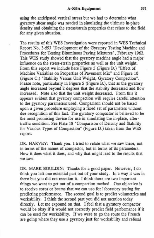
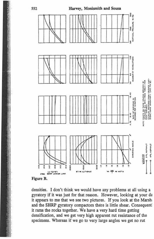
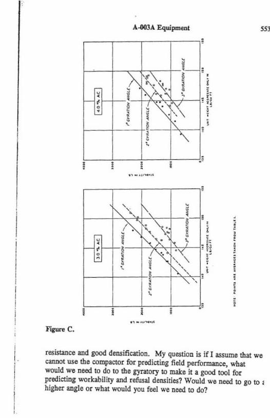
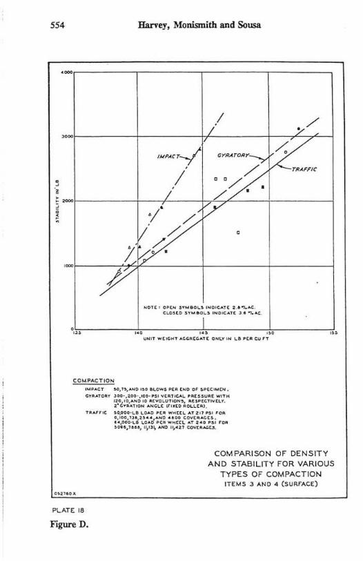
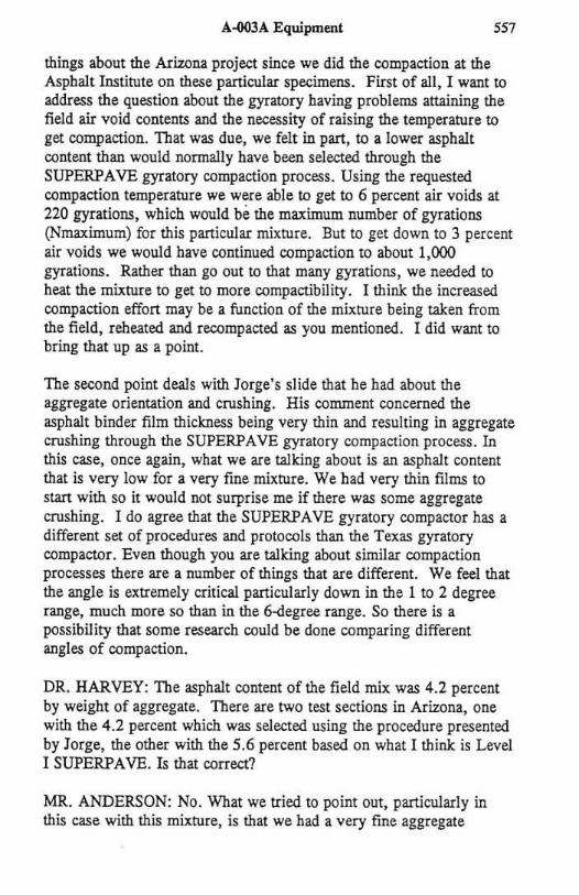
The results of this WES Investigation were reported in WES Technical Report No . 3-591 "Development of the Gyratory Testing Machine and Procedures for Testing Biruminous Paving Mixrures" , February 1962. This WES srudy showed that the gyratory machine angle had a major influence on the stress-strain properties as well as the unit weight. From this report we include here Figure 5 (Figure B.) "Effect of Machine Variables on Properties of Pavement Mix" and Figure 10 (Figure C.) "Stability Versus Unit Weight, Gyratory Compaction". Please note, panicularly in FiiUre 5 (Figure B.), that as the gyratory angle increased beyond 2 degrees that the stability decreased and flow increased. Note also that the unit weight decreased. From this it appears evident that gyratory compaction will require careful attention to the gyratory parameters used. Comparison should not be based upon a given procedure employing a fixed set of parameters without due recognition of this fact. The gyratory compactor is believed to be the most promising device for use in simulating the in'place, aftertraffic condition. See Plate 18 ·Comparison of Density and Stability for Various Types of Compaction" (Figure D .) taken from the WES report.
DR. HARVEY: Thank you. I tried to relate what we saw there, not in terms of the names of compactor, but in terms of its parameters. How it does what it does, and why that might lead to the results that we saw.
DR. MARK BOULDIN: Thanks for a good paper. However, I do think you left one essential pan out of your srudy. In a way it was in there but you did not mention it. I think there are two important things we want to get out of a compaction method. One objective is to receive cores or beams that we can use for laboratory testing for predicting performance. The second goal is to predict volumetrics and workability. I think the second pan you did not mention today directly. Let me expound on that. I feel that a gyratory compactor would be okay if it would not correctly predict field performance if it can be used for workability. If we were to go the route the French are going where they use a gyratory just for workability and refusal
552 HarTey, Monismith and Sousa
i\
11\~
\t
I'\~ . . - . .t:: . . !!l!!1! .. ~,..,., ...... .".,. ........... -
Figure B.
11\lll
. . , ., .. ...........
!
!
!
.
, ,
, • ! r , , ,
I • i
",-,-,-n-,; II Ii 'I
HH-ttt-i: ;1 L..L-LJ.-LLJ .
, \
,
l\ , , , , , , , - ":" .. _<n,
, •
densities. I don't think we would have any problems at all using a gyratory if it was just for that reason. However, looking at your d. it appears to me that we see two pictures. If you look at the Marsh. and the SHRP gyratory compactors there is linle shear. Consequen~ it rams the rocks together. We have a very hard time gening densification. and we get very high apparent rut resistance of the specimens. Whereas if we go to very large angles we get no rut
I
I.
FIgUl'e C.
A-OOJA Equipment
~--~---f.----t·I--~·' ! !
,
~'v ,
1", • " i- , ,A; , ''\ , . !
0 I i'..'y j, ; < 1-, !
, • {~ ,:'\ " !
~ • f'\>, ! , ! " " • ;
I I I .-,, ~ " ..... ,.
5S3
, i
i
resistance and good densification. My question is if I assume that we cannot use the compactor for predicting field performance, what would we need to do to the gyratory to make it a good tool for predicting workability and refusal densities? Would we need to go to I higher angle or what would you feel we need to do?
SS4 Harvey, Monismitb and Sousa
· · , · , ~
.-
// ;.- / ,-,f----------+----------"'L---------+--c,<c,~_1
"":.:;~" / :;:::/. . ""C--------+---+----~rL,L----~------~
V/ /'/'
l/ ./. 1 !=.
'-r---- -;t,,>!L--------t---------ir--------j p N,U , 0" . .. ".o~. '''O'~.'' I .. .... "¢. (I.." ••• "' .o~. 'N.","', " .... "'.
I .,\,.,-------"!.,.-------,,! .• ,--------,,,f..,------"j" """ .. . >O~ •• 00 ... .. ' I 0 .. ,-. ,,' ..... . w "
..... CT .. ,", oN" ... ,,,.W, .,. 'N, 0' "«"',N. c, ••• "", '0.· .••• · .... · •• ' v,., ....... "U.~" "" ' "
~."G~:::.N:':' :::; .. O.'~T:~.;.:...:::~T"' ... ' . .. M . ", ...... _ ........... w~ .... ... ,."." ' ••
:~::.,'.~~>: ....... ~~; :..~~~~~':~~~; TOO
'''',>0", I~"'''''' ",'" CO>'<.~
COM PARISO N OF DENSIT Y A N D STABILIT Y FOR VARIOUS
TYPES OF COMPACTION IT£"'S 3 ANt).oI (SURFACE)
PLATE III
Figure D.
A~3A Equipment sss
DR. HARVEY: I think the gyratory is a good tool for looking at compactability and the French bave had a lot of success with it. I have not looked at the data. You would have to correlate your construction equipment and that might be different between here and there. I think you have to look at the data. I can't suggest a given angle, or a given speed of rotation, or anything like that at this time. You would have to look at what kind of compaction you could achieve with different equipment and then relate that statistically to an empirical database as the French have done with those parameters for the gyratory compactor. One thing we saw here is that the specific angie, rotation, speed, and whatever other parameters the SHRP gyratory has could not achieve the field density. So at least that is one point towards beginning an evaluation of using it as a tool for measuring compactability.
DR. BOULDIN: Could you explain from your data if you saw any advantages at the moment in going with the SHRP compactor or JUSt using the French?
DR. HARVEY: I can't answer that.
PROFESSOR REYNALDO ROQUE: 1 have a question on the idea that trafficking improves ru t resistance. I was wondering if you could explain that a little more? Is that a direct effect or are you just talking about the fact that you are starting at a different air void level in terms of testing your material and when you evaluate it at higher air voids what would have been additional compaction you are now counting as rutting in the lab? Because traffic is what causes rutting is it not? Am I interpreting that correctly?
DR. HARVEY : Yes. That is right. We did not do a conclusive study on this at all. But just general observations from the field cores we bad in and out of the wheelpath. For the RAP mix we saw minimal densification but we did see an improvement in the pennanent shear deformation resistance. Increased pennanent shear deformation resistance is a function of two things, the first being compaction or funher densification caused by traffic. But we think it is also due to working of the aggregates and asphalt by the traffic. In some cases even without densification, a mix that was not designed well (an unstable mix) either as it densities it will reach a peak strength that will be lower than fo r a more stable mix; or with that increased
'" HarTey. Monismith and Sousa
trafficking it will not develop increased strength but rather decreased strength. That is what we saw in the asphalt rubber section.
PROF. ROQUE: SO a poor mix would not be improved by traffic?
DR. HARVEY: Right.
PROF. ROQUE: In terms of some work we are doing I am interested in how you did it. For a standard design you would essentially weigh every aggregate at every sieve to the nearest gram so that you can get consistency within that small specimen that you are trying to produce. When y Oll take these large quantities it appears you were taking from in front of a paver. and now you start producing small specimens like gyratory specimens, etc., how do you guarantee that1 What controls do you take to do that?
DR. HARVEY: They were taken from the same point in front of the paver. I marched along in front of the paver and picked a point .
PROF. ROQUE: That is not my question. My question is once you get back: to the lab how do you separate that such that every specimen bas like gradations. In the way we do in a mix design where we guarantee that by weighing every sieve size.
DR. HARVEY: In this case it was done by randomization. We took the amount of material for each sample randomly from the larger pot of material.
PROF. ROQUE: Was there some kind of divider of some sort?
DR. HARVEY: No. We did not run them through dividers because we did not want to keep doing that over and over to get to specimen size masses. For example. if we had six specimens. three gyratory and three rolling wheel, we would take the material for each randomly from the larger mass of material. So there may be some variability there.
MR. MIKE ANDERSON: John, thank you for your presentation. I bad a whole handful of comments most of which have been already made by Byron and John. I am forced to agree with a number of the comments made by Mark Bouldin. J would like to point out several
A-003A Equipment 557
things about the Arizona project since we did the compaction at the Asphalt Institute on these particular specimens. First of al l, I want to address the question about the gyratory having problems attaining the field air void contents and the necessity of raising the temperature to get compaction. That was due, we felt in part, to a lower asphalt content than would normally have been selected through the SUPERPA VE gyratory compaction process. Using the requested compaction temperature we were able to get to 6 percent air voids at 220 gyrations, which would be the maximum number of gyrations (Nmaximum) for this particular mixture. But to get down to 3 percent air voids we would have COntinued compaction to about 1,000 gyrations. Rather than go out to that many gyrations, we needed to heat the mixture to get to more compactibility. I think: the increased compaction effon may be a function of the mixture being taken from the field, reheated and recompacted as you mentioned. I did want to bring that up as a point.
The second point deals with Jorge's slide that he had about the aggregate orientation and crushing. His comment concerned the asphalt binder film thickness being very thin and resulting in aggregate crushing through the SUPERPAVE gyratory compaction process. In this case, once again, what we are talking about is an asphalt content that is very low for a very fine mixture. We had very thin films to start with so it would not surprise me if there was some aggregate crushing. I do agree that the SUPERPAVE gyratory compactor has a different set of procedures and protocols than the Texas gyratory compactor. Even though you are talking about similar compaction processes there are a number of things that are different. We feel that the angle is extremely critical particularly down in the I to 2 degree range, much more 50 than in the 6-degree range. So there is a possibility that some research could be done comparing different angles of compaction.
DR. HARVEY: The asphalt content of the field mix was 4.2 percent by weight of aggregate. There are two test sections in Arizona, one with the 4.2 percent which was selected using the procedure presented by Jorge, the other with the 5.6 percent based on what I think: is Level I SUPERPA VE. Is that correct?
MR. ANDERSON: No . What we tried to point out, particularly in this case with this mixture, is that we had a very fine aggregate
'58 Harvey, Monismith and Sousa
structure that would have required higher than normal asphalt content. As a maner of fact when we went througb the volumetrics, which gets back to Mark Bouldin's comments, we had a mixture that was very borderline. Actually too Iowan VMA. below the minimum. I think minimum required was 13.0 percent and we were about 12.9 percent for this mixture. In addition this was a mixture with the densification parameters of 89 percent right at the maximum allowable level at initial number of gyrations (Ninitial) as well as baving Nmaximum well below 98 percent. So the mixture compacted using the SUPERPA VE gyratory compaction had a very flat slope which tends to indicate a weaker aggregate structure. Given that this would have been one of several trial blends, it is possible in puning together a mixture design that this mixture would not have been one of the aggregate blends selected by the SUPERPAVE Level I mix design procedure. Our comments were mainly relative to that.
DR. HARVEY: Thank you.
PROFESSOR CARL MONISMITH: I would like to step back and take a general look at where we are and what is being discussed. I think whenever one designs a mix, the person should ensure that the mix tested in the laboratory has the same propenies as the mix that is compacted in the field and subjected to field conditions. Thus we have attempted, as a pan of the activities that we have been involved in, staning with SHRP and then subsequently, to adhere to this guideline. We are not only concerned with density but also with the mix structure so that the response (e.g. the resistance to performance deformation) is going to be the same in both the laboratory compacted specimen and that compacted in the field. Similarly the specimens should have the same fatigue resistance, the same resistance to thermal cracking, etc. This comparability is the imponant consideration. Accordingly, we have attempted to provide data for the profession illustrating the influence of method of compaction on the resistance of mixes to permanent deformation, by testing specimens over which we have some control. The evidence we have generated thus far suggests that rolling wheel compaction produces more realistic specimens than those produced by gyratory compaction. This evidence is based not only density but rather resistance to permanent deformation as measured in the simple shear device. This is not meant to condemn the gyratory compactor. Rather it suggests that we proceed with caution and ensure that the method of compaction selected produces
A-003A Equipmenl
realistic test specimens.
During this discussion we have seen a difference of opinion expressed relative to the information presemed. This is healthy. We have suggested, based on tests on specimens produced by rolling wheel compaction, a design binder content of 4.2 percent (by weight of aggregate). Those using the SHRP Level I procedure have suggested a binder content at least 1 percent higher. There is the possibility, however, that we tested a different material than that used in the SRRP Level I procedure. Is that a correct statement, John?
DR. HARVEY: No. It was the same aggregate.
PROF. MONISMIl1:I : But was it crushed more than what we had tested initially?
DR. HARVEY: We did the second mix design using the same aggregate as the SUPERPAVE mix.
PROF. MONISMITH: Here we have the opportunity to see whether or not the rolling wheel or the gyratory, or both are correct. Part of my concern with gyratory compaction stems from my contact with Jacques Bonnot of the LCPC who served as an advisory to the SHRP A-003A project. He has stated. that the gyratory compactor is used only to check the workability of the mix . The LCPC staff do not use gyratory compaction to produce specimens for mix testing in the laboratory. Rather they use roll ing wheel compaction. Thus I 'm urging that we keep an open mind and make certain the data we look at and the response characteristics that we are concerned with are going to be the same between the laboratory and the field.
AurnoRS' CLOSURE: The resullS of the WES investigation discussed by Mr. McRae are similar to those presented in our paper. The information emphasizes that the parameters (e.g. angle of gyration) used for gyratory compaction require careful attention because they can produce dramatically different properties for the same mix. However, the conclusion that should be drawn from these results is that there is a substantial amount of work to be done to determine parameters required to duplicate field compaction. Of particular import in Mr. McRae's discussion is his statement that a given set of parameters will not duplicate field compaction for
Ii , , 560 Harvey. Monismith and Sousa
different mixes, implying that a compaction study of the kind presented in this paper would be required for each mix.
Of the laboratory compaction methods available today, we believe th~ specimens produced by rolling wheel compaction best duplicate the properties of specimens compacted in the field. We also believe, base on other research we have performed as part of the SHRP A-003A project, that rolling wheel compaction is competitive in terms of labo. and materials efficiency with the available gyratory compactors. The rolling wheel compactor we are currently using is an inexpensive application of the rolling wheel principle. Based on the infonnation presented herein, as well as the European experience, we strongly believe that development of an automated rolling wheel compactor should be a high priority activity for the asphalt pavement communit) in the U.S.


![GB5 mix design high-performance - Sabita...- Compacting ability [NF EN 12697-31]: Gyratory compactor - Moisture resistance [NF EN 12697-12]: Duriez test - Rutting resistance at 60°C](https://img.pdfslide.net/doc/110x75/60c8683095d8fe32f1212707/gb5-mix-design-high-performance-compacting-ability-nf-en-12697-31-gyratory.jpg)