Embed Size (px)
Citation preview
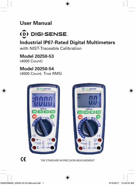
THE STANDARD IN PRECISION MEASUREMENT
User Manual
Industrial IP67-Rated Digital Multimeterswith NIST-Traceable Calibration
Model 20250-53 (4000 Count)
Model 20250-54 (4000 Count, True RMS)
1065DGMAN_20250-53-54 Manual.indd 1 8/16/2017 10:42:05 AM
2
Introduction
Digi-Sense Industrial Digital Multimeters (model 20250-53; TRMS model 20250-54) are a must-have on your electrical tool belt—especially for those who need a rugged and reliable meter. These versatile and simple-to-use units safely measure the full range of common parameters including voltage, current, resistance, capacitance, frequency, temperature, and more. All this technology is packaged in a double-insulated housing that meets IP67 requirements. The instruments are fully tested and calibrated to NIST-traceable standards. Careful use of the meter will provide years of reliable service.
Safety
Safety Warnings
The following safety information must be observed to insure maximum personal safety during the operation at this meter:
• Measurements beyond the maximum selected range must not be attempted.
• Extreme care must be taken when measuring above 50 V, especially on live bus-bars.
• To measure voltage, the instrument must not be switched to a current or resistance range, or to the diode check or buzzer position.
• Circuits must be de-energized and isolated before carrying out resistance tests.
• The rotary function switch must only be turned after removing test connections.
• All external voltages must be disconnected from the instrument before removing the battery.
1065DGMAN_20250-53-54 Manual.indd 2 8/16/2017 10:42:05 AM
3
• Test leads and prods must be in good order, clean, and with no broken or cracked insulation.
• UK Safety Authorities recommend the use of fused test leads when measuring voltage on high energy systems.
• Replacement fuses must be of the correct type and rating.
• The instrument must not be used if any part of it is damaged.
• Warnings and precautions must be read and understood before an instrument is used. They must be observed dur-ing the operation of this instrument.
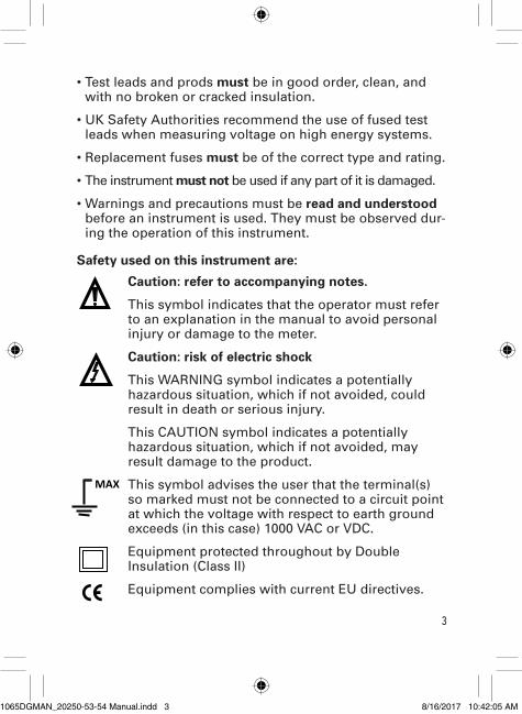
Safety used on this instrument are:
Caution: refer to accompanying notes.
This symbol indicates that the operator must refer to an explanation in the manual to avoid personal injury or damage to the meter.
Caution: risk of electric shock
This WARNING symbol indicates a potentially hazardous situation, which if not avoided, could result in death or serious injury.
This CAUTION symbol indicates a potentially hazardous situation, which if not avoided, may result damage to the product.
This symbol advises the user that the terminal(s) so marked must not be connected to a circuit point at which the voltage with respect to earth ground exceeds (in this case) 1000 VAC or VDC.
Equipment protected throughout by Double Insulation (Class II)
Equipment complies with current EU directives.
MAX 500V
1065DGMAN_20250-53-54 Manual.indd 3 8/16/2017 10:42:05 AM
4
Unpacking
Check individual parts against the list of items below. If anything is missing or damaged, please contact your instrument supplier immediately.
1. Instrument
2. Test leads
3. One type K temperature probe (model 20250-54 only)
4. One 9 V battery
5. Carrying case
6. User manual
7. NIST-traceable calibration report with data
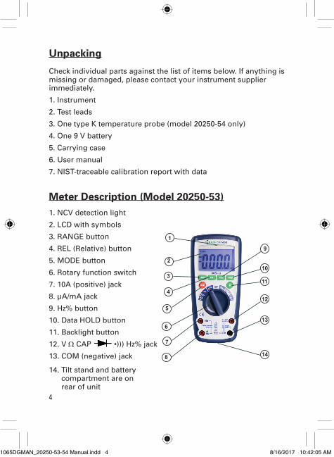
Meter Description (Model 20250-53)1. NCV detection light
2. LCD with symbols
3. RANGE button
4. REL (Relative) button
5. MODE button
6. Rotary function switch
7. 10A (positive) jack
8. µA/mA jack
9. Hz% button
10. Data HOLD button
11. Backlight button
12. V Ω CAP •))) Hz% jack
13. COM (negative) jack
14. Tilt stand and battery compartment are on rear of unit
1
2
3
4
5
6
7
8
9
10
11
12
13
14
1065DGMAN_20250-53-54 Manual.indd 4 8/16/2017 10:42:05 AM
5
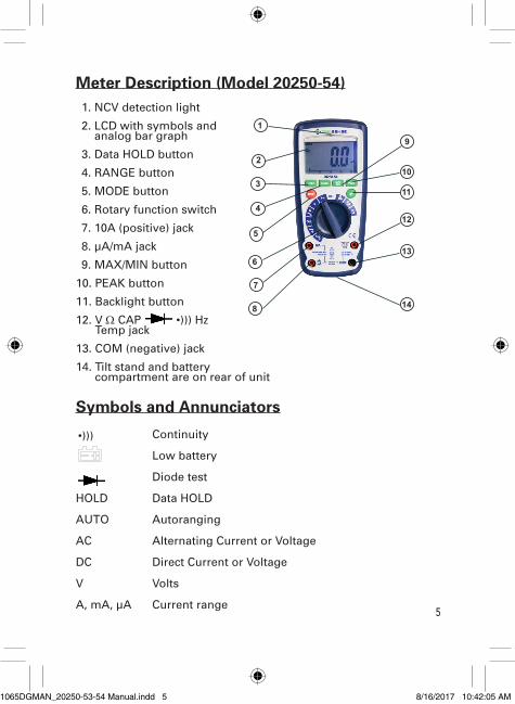
Meter Description (Model 20250-54)1. NCV detection light
2. LCD with symbols and analog bar graph
3. Data HOLD button
4. RANGE button
5. MODE button
6. Rotary function switch
7. 10A (positive) jack
8. µA/mA jack
9. MAX/MIN button
10. PEAK button
11. Backlight button
12. V Ω CAP •))) Hz Temp jack
13. COM (negative) jack
14. Tilt stand and battery compartment are on rear of unit
Symbols and Annunciators
Continuity
Low battery
Diode test
HOLD Data HOLD
AUTO Autoranging
AC Alternating Current or Voltage
DC Direct Current or Voltage
V Volts
A, mA, µA Current range
1
2
3
4
5
6
7
8
9
10
11
12
13
14
•)))
1065DGMAN_20250-53-54 Manual.indd 5 8/16/2017 10:42:05 AM
6
Setup and Operation
To turn on the instrument turn the rotary function switch from the OFF position to any measurement range.
NOTE: For best battery life ALWAYS turn the rotary function switch to the OFF position when the meter is not in use. Meter has Auto power-off that automatically shuts the meter off if 30 minutes elapse between uses.
NOTE: On some low AC and DC voltage ranges, with the test leads not connected to a device, the display may show a random, changing reading. This is normal and is caused by the high-input sensitivity. The reading will stabilize and give a proper measurement when connected to a circuit.
MODE Button
To select AC or DC measurement when Voltages, Amps, mA , µA, Ω, , •))), CAP, or Hz% are selected.
HOLD Button
The Data HOLD function allows the meter to "freeze" a measurement for later reference.
1. Press the HOLD button to “freeze” the reading on the display. The indicator “HOLD” will be appear in the display.
2. Press the HOLD button to resume normal operation.
1065DGMAN_20250-53-54 Manual.indd 6 8/16/2017 10:42:05 AM
7
RANGE Button
When the meter is first turned on, it automatically defaults to Autoranging. This automatically selects the best range for the measurements being made and is generally the optimal mode for most measurements. For measurement situations requiring that a range be manually selected, perform the following:
1. Press the RANGE button. The “Auto Range” display indicator will turn off. The “Manual Range” display indicator will turn on
2. Press the RANGE button to step through the available ranges until you select the range you want.
3. Press and hold the RANGE button for 2 seconds to exit the manual ranging mode and return to autoranging.
REL Button (Model 20250-53 only)
The relative (REL) measurement feature allows you to make measurements relative to a stored reference value. A reference voltage, current, etc., can be stored and measurements made in comparison to that value. The displayed value is the difference between the reference value and the measured value.
Note: This function works with all functions except Hz%, Diode, and Continuity.
1. Press the REL button to store the reading in the display and the "REL" indicator will appear on the display.
2. The display will now indicate the difference between the stored value and the measured value.
3. Press the REL button again to resume normal operation.
1065DGMAN_20250-53-54 Manual.indd 7 8/16/2017 10:42:05 AM
8
MAX/MIN Button (Model 20250-54 only)
The MAX/MIN function allows the meter to capture the highest or lowest reading for later reference.
1. Press the MAX/MIN button to begin measurement. The indicator “MAX” or “MIN” will appear in the display.
2. If the “MAX MIN” messages are flashing, the instrument is in MAX/MIN mode but not recording, press the MAX/MIN button to select a mode.
3. To resume operation, hold down the MAX/MIN button for 2 seconds.
PEAK Hold Button (Model 20250-54 only)
The PEAK Hold function captures the peak AC voltage or current. The meter can capture negative or positive peaks as fast as 1 millisecond in duration.
1. Set the rotary function switch to the A or V position.
2. Press the MODE button to select “AC”.
3. Allow time for the display to stabilize.
4. Press and hold the PEAK button until “CAL” appears in the display.
5. This procedure will zero the range selected.
6. Press the PEAK button; the indicator “Pmax” will be displayed.
7. The display will update each time a higher positive peak occurs.
8. Press the PEAK button again; the indicator “Pmin” will be displayed. The display will now update and indicate the lowest negative peak.
1065DGMAN_20250-53-54 Manual.indd 8 8/16/2017 10:42:05 AM
9
9. To return to normal operation, press and hold the PEAK button until the “Pmax” or “Pmin” indicator switches off.
10. If the rotary function switch position is changed after a calibration, the PEAK Hold calibration must be repeated for the new function selected.
BACKLIGHT Button
1. Press the BACKLIGHT button to switch on the display light.
2. Press BACKLIGHT button again to exit the light mode.
AC and DC Voltage Measurements
1. Insert the black test lead into the negative COM terminal and the red test lead into the positive V terminal.
2. Set the rotary function switch to the V AC/DC position.
3. Press the MODE button to select “AC” or “DC” voltage.
4. Connect the test leads in parallel to the circuit under test.
5. Read the voltage measurement on the display.
AC and DC Current Measurements
1. Insert the black test lead banana plug into the negative COM jack.
2. For current measurements up to 4000 µA, set the rotary function switch to the µA position and insert the red test lead banana plug into the (µA, mA) jack.
3. For current measurements up to 400 mA, set the rotary function switch to the mA range and insert the red test lead banana plug into the (µA, mA) jack.
1065DGMAN_20250-53-54 Manual.indd 9 8/16/2017 10:42:05 AM
10
4. For current measurements up to 10 A, set the rotary function switch to the 10A position and insert the red test lead banana plug into the 10A jack.
5. Press the MODE button to select “AC” or “DC” current.
6. Remove power from the circuit under test, then open the circuit at the point where you wish to measure current.
7. Touch the black test probe tip to the negative side of the circuit and touch the red test probe tip to the positive side of the circuit.
8. Apply power to the circuit.
9. Read the current measurement on display. The proper decimal point, value, and symbol will be indicated.
Resistance Measurement
WARNING: To avoid electric shock, disconnect power to the unit under test and discharge all capacitors before taking any resistance measurements. Remove the batteries and unplug the line cords.
1. Set the rotary function switch to the Ω position.
2. Insert the black test lead plug into the negative COM socket and the red test lead plug into the positive Ω jack.
3. Press the MODE button until “Ω” appears in the display.
4. Touch the test probe tips across the circuit or part under test. It is best to disconnect one side of the part under test so the rest of the circuit will not interfere with the resistance reading.
5. Read the resistance measurement on the display. The display will indicate the proper decimal point, value, and symbol.
1065DGMAN_20250-53-54 Manual.indd 10 8/16/2017 10:42:05 AM
11
Continuity Check
WARNING: To avoid electric shock, never measure continuity on circuits or wires that have voltage on them.
1. Set the rotary function switch to the •))) position.
2. Insert the black lead plug into the COM socket and the red test lead plug into the positive •))) socket.
3. Press the MODE button until “•)))” appears in the display.
4. Touch the test probe tips to the circuit or wire you wish to check.
5. If the resistance is less than 50 Ω (20250-53) or 35 Ω (20250-54), the audible signal will sound. The display will also show the actual resistance in ohms.
Diode Test
WARNING: To avoid electric shock, do not test any diode that has voltage on it.
1. Set the rotary function switch to the position.
2. Insert the black test lead plug into the COM socket and the red test lead plug into the socket.
3. Press the MODE button until “ ” appears in the display.
4. Touch the test probe tips to the diode or semiconductor junction you wish to test. Note the meter reading.
5. Reverse the probe polarity by switching probe position. Note this reading.
1065DGMAN_20250-53-54 Manual.indd 11 8/16/2017 10:42:05 AM
12
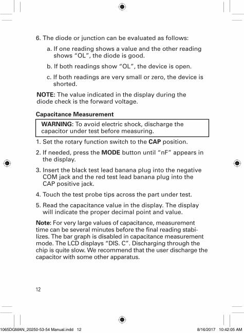
6. The diode or junction can be evaluated as follows:
a. If one reading shows a value and the other reading shows “OL”, the diode is good.
b. If both readings show “OL”, the device is open.
c. If both readings are very small or zero, the device is shorted.
NOTE: The value indicated in the display during the diode check is the forward voltage.
Capacitance Measurement
WARNING: To avoid electric shock, discharge the capacitor under test before measuring.
1. Set the rotary function switch to the CAP position.
2. If needed, press the MODE button until “nF” appears in the display.
3. Insert the black test lead banana plug into the negative COM jack and the red test lead banana plug into the CAP positive jack.
4. Touch the test probe tips across the part under test.
5. Read the capacitance value in the display. The display will indicate the proper decimal point and value.
Note: For very large values of capacitance, measurement time can be several minutes before the final reading stabi-lizes. The bar graph is disabled in capacitance measurement mode. The LCD displays “DIS. C”. Discharging through the chip is quite slow. We recommend that the user discharge the capacitor with some other apparatus.
1065DGMAN_20250-53-54 Manual.indd 12 8/16/2017 10:42:05 AM
13
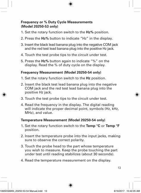
Frequency or % Duty Cycle Measurements (Model 20250-53 only)
1. Set the rotary function switch to the Hz% position.
2. Press the Hz% button to indicate “Hz” in the display.
3. Insert the black lead banana plug into the negative COM jack and the red test lead banana plug into the positive Hz jack.
4. Touch the test probe tips to the circuit under test.
5. Press the Hz% button again to indicate “%” on the display. Read the % of duty cycle on the display.
Frequency Measurement (Model 20250-54 only)
1. Set the rotary function switch to the Hz position.
2. Insert the black test lead banana plug into the negative COM jack and the red test lead banana plug into the positive Hz jack.
3. Touch the test probe tips to the circuit under test.
4. Read the frequency in the display. The digital reading will indicate the proper decimal point, symbols (Hz, kHz, MHz), and value.
Temperature Measurement (Model 20250-54 only)
1. Set the rotary function switch to the Temp °C or Temp °F position.
2. Insert the temperature probe into the input jacks, making sure to observe the correct polarity.
3. Touch the probe head to the part whose temperature you wish to measure. Keep the probe touching the part under test until reading stabilizes (about 30 seconds).
4. Read the temperature measurement on the display.
1065DGMAN_20250-53-54 Manual.indd 13 8/16/2017 10:42:05 AM
14
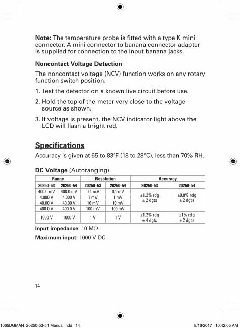
Note: The temperature probe is fitted with a type K mini connector. A mini connector to banana connector adapter is supplied for connection to the input banana jacks.
Noncontact Voltage Detection
The noncontact voltage (NCV) function works on any rotary function switch position.
1. Test the detector on a known live circuit before use.
2. Hold the top of the meter very close to the voltage source as shown.
3. If voltage is present, the NCV indicator light above the LCD will flash a bright red.
SpecificationsAccuracy is given at 65 to 83°F (18 to 28°C), less than 70% RH.
DC Voltage (Autoranging)Range Resolution Accuracy
20250-53 20250-54 20250-53 20250-54 20250-53 20250-54400.0 mV 400.0 mV 0.1 mV 0.1 mV
±1.2% rdg ± 2 dgts
±0.8% rdg ± 2 dgts4.000 V 4.000 V 1 mV 1 mV
40.00 V 40.00 V 10 mV 10 mV400.0 V 400.0 V 100 mV 100 mV
1000 V 1000 V 1 V 1 V ±1.2% rdg ± 4 dgts
±1% rdg ± 2 dgts
Input impedance: 10 MΩ
Maximum input: 1000 V DC
1065DGMAN_20250-53-54 Manual.indd 14 8/16/2017 10:42:05 AM
15
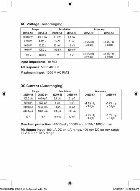
AC Voltage (Autoranging)Range Resolution Accuracy
20250-53 20250-54 20250-53 20250-54 20250-53 20250-54400.0 mV 400.0 mV 0.1 mV 0.1 mV
±1.5% rdg ± 3 dgts
±1.0% rdg ± 3 dgts
4.000 V 4.000 V 1 mV 1 mV40.00 V 40.00 V 10 mV 10 mV400.0 V 400.0 V 100 mV 100 mV
1000 V 1000 V 1 V 1 V ±1.5% rdg ± 5 dgts
±1.2% rdg ± 5 dgts
Input impedance: 10 MΩ
AC response: 50 to 400 Hz
Maximum input: 1000 V AC RMS
DC Current (Autoranging)Range Resolution Accuracy
20250-53 20250-54 20250-53 20250-54 20250-53 20250-54400.0 µA 400.0 µA 0.1 µA 0.1 µA
±1.2% rdg ± 3 dgts
±1.2% rdg ± 5 dgts
4000 µA 4000 µA 1 µA 1 µA40.00 mA 40.00 mA 10 µA 10 µA400.0 mA 400.0 mA 100 µA 100 µA
10 A 10 A 10 mA 10 mA ±2.5% rdg ± 3 dgts
±1.5% rdg ± 5 dgts
Overload protection: FF500mA / 1000V and F10A / 1000V fuse
Maximum input: 400 µA DC on µA range, 400 mA DC on mA range, 10 A DC on 10 A range
1065DGMAN_20250-53-54 Manual.indd 15 8/16/2017 10:42:06 AM
16
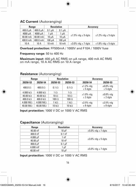
Range Resolution Accuracy400.0 µA 400.0 µA 0.1 µA 0.1 µA
±1.5% rdg ± 5 dgts ±1.2% rdg ± 5 dgts4000 µA 4000 µA 1 µA 1 µA40.00 mA 40.00 mA 10 µA 10 µA400.0 mA 400.0 mA 100 µA 100 µA
10 A 10 A 10 mA 10 mA ±3.0% rdg ± 7 dgts ±1.8% rdg ± 5 dgts
AC Current (Autoranging)
Overload protection: FF500mA / 1000V and F10A / 1000V fuse
Frequency range: 50 to 400 Hz
Maximum input: 400 µA AC RMS on µA range, 400 mA AC RMS on mA range, 10 A AC RMS on 10 A range
Resistance (Autoranging)
Input protection: 1000 V DC or 1000 V AC RMS
Range Resolution Accuracy20250-53 20250-54 20250-53 20250-53 20250-54 20250-53
400.0 Ω 400.0 Ω 0.1 Ω 0.1 Ω ±1.2% rdg ± 5 dgts
±0.8% rdg ± 5 dgts
4.000 kΩ 4.000 kΩ 1 Ω 1 Ω±1.0% rdg ± 2 dgts
±0.8% rdg ± 2 dgts40.00 kΩ 40.00 kΩ 10 Ω 10 Ω
400.0 kΩ 400.0 kΩ 100 Ω 100 Ω4.000 MΩ 4.000 MΩ 1 kΩ 1 kΩ ±2.5% rdg
± 8 dgts±2.5% rdg ± 8 dgts40.00 MΩ 40.00 MΩ 10 kΩ 10 kΩ
Capacitance (Autoranging)Range Resolution Accuracy
40.00 nF 10 pF ±5.0% rdg ± 7 dgts400.0 nF 0.1 nF
±3.0% rdg ± 5 dgts4.000 µF 1 nF40.00 µF 10 nF400.0 µF 0.1 µF4.000 mF 1 µF ±5.0% rdg ± 7 dgts40.00 mF 10 µF
Input protection: 1000 V DC or 1000 V AC RMS
1065DGMAN_20250-53-54 Manual.indd 16 8/16/2017 10:42:06 AM
17
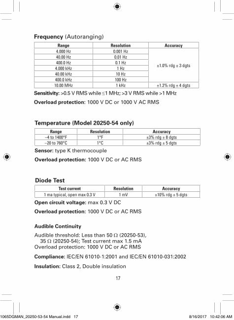
Range Resolution Accuracy4.000 Hz 0.001 Hz
±1.0% rdg ± 3 dgts
40.00 Hz 0.01 Hz400.0 Hz 0.1 Hz
4.000 kHz 1 Hz40.00 kHz 10 Hz400.0 kHz 100 Hz10.00 MHz 1 kHz ±1.2% rdg ± 4 dgts
Sensitivity: >0.5 V RMS while ≤1 MHz; >3 V RMS while >1 MHz
Overload protection: 1000 V DC or 1000 V AC RMS
Frequency (Autoranging)
Range Resolution Accuracy–4 to 1400°F 1°F ±3% rdg ± 8 dgts–20 to 760°C 1°C ±3% rdg ± 5 dgts
Test current Resolution Accuracy1 ma typical, open max 0.3 V 1 mV ±10% rdg ± 5 dgts
Temperature (Model 20250-54 only)
Sensor: type K thermocouple
Overload protection: 1000 V DC or AC RMS
Diode Test
Open circuit voltage: max 0.3 V DC
Overload protection: 1000 V DC or AC RMS
Audible Continuity
Audible threshold: Less than 50 Ω (20250-53), 35 Ω (20250-54); Test current max 1.5 mA Overload protection: 1000 V DC or AC RMS
Compliance: IEC/EN 61010-1:2001 and IEC/EN 61010-031:2002
Insulation: Class 2, Double insulation
1065DGMAN_20250-53-54 Manual.indd 17 8/16/2017 10:42:06 AM
18
Overvoltage category: CAT IV 600 V, CAT III 1000 V
NOTE: These meters meet CAT III and CAT IV IEC 61010 standards. The IEC 61010 safety standard defines four overvoltage categories (CAT I to IV) based on the magnitude of danger from transient impulses. CAT III meters are designed to protect against transients in fixed-equipment installations at the distribution level; CAT IV meters are designed to protect against transients from the primary supply level (overhead or underground utility service).
Max voltage between any terminal and earth ground: 1000 V DC/AC RMS
Display: 4000 count LCD, 13⁄16" (21 mm) high
Polarity: Automatic, (–) negative polarity indication
Overrange indication: “OL” mark indication is displayed
Low-battery indication: Battery symbol “ ” is displayed
Measurement rate: 2 times per second nominal
Operating environment: 14 to 122°F (–10 to 50°C) at <70% RH
Storage temperature: –4 to 140°F (–20 to 60°C) at <80% RH
Relative humidity: 90% (0 to 30°C); 75% (30 to 40°C); 45% (40 to 50°C)
For inside use, max height: Operating: 9842 ft (3000 m), Storage 32,808 ft (10,000 m)
Pollution degree: 2
Power: One 9 V battery, NEDA 1604, IEC 6F22
Auto power-off: Approximately after 30 minutes of inactivity
Weight: 13 oz (375 g)
Dimensions: 73⁄16" x 31⁄4" x 23⁄16" (18.2 x 8.2 x 5.5 cm)
1065DGMAN_20250-53-54 Manual.indd 18 8/16/2017 10:42:06 AM
19
Maintenance, Recalibration, and Repair
Cleaning and Storage
• Clean meter with a damp cloth and mild detergent when necessary. Do not use solvents or abrasives.
• Store the meter in an area with moderate temperature and humidity.
Battery Replacement
WARNING: To avoid electric shock, disconnect the test leads from any source of voltage before remov-ing the battery door.
1. When the battery becomes exhausted or drops below operating voltage, the battery warning symbol will appear in the right-hand side of the LCD. The battery should be replaced.
2. Disconnect the test leads from the meter.
3. Open the battery door by loosening the screw using a Phillips head screwdriver.
4. Insert the battery into battery holder, observing the correct polarity.
5. Put the battery door back in place. Secure with the two screws.
6. Dispose of the old battery properly.
WARNING: To avoid electric shock, do not operate your meter until the battery door is in place and fastened securely.
1065DGMAN_20250-53-54 Manual.indd 19 8/16/2017 10:42:06 AM
20
For Product and Ordering Information, Contact:
Toll-Free: 1-800-323-4340 Phone: 1-847-549-7600 Fax: 1-847-247-2929 ColeParmer.com/Digi-Sense
Toll-Free: 1-800-358-5525 Phone: 1-847-327-2000 Fax: 1-847-327-2700 Davis.com/Digi-Sense
Manual Part No. 00101-871065DGMAN_20250-53, -54
Phone: 1-866-INNOCAL (1-866-466-6225) Fax: 1-847-327-2993 E-mail: [email protected] Web: InnoCalSolutions.com
It is recommended that Digi-Sense products are calibrated annually to ensure proper function and accurate measure-ments; however, your quality system or regulatory body may require more frequent calibrations.
To schedule your recalibration, please contact InnoCal, an ISO 17025 calibration laboratory accredited by A2LA.
1065DGMAN_20250-53-54 Manual.indd 20 8/16/2017 10:42:06 AM