Embed Size (px)
Citation preview

1
UniSwitch Withdrawable type Circuit Breaker Cubicles Installation, service and maintenance instruction manual

2
Your safety first – at all times! This is why our instruction manual begins with the following recommendations: • Only install switchgear and/or switchboards in closed rooms suitable for electrical equipment. • Ensure that installation, operation and maintenance are carried out by specialist electricians only. • Fully comply with the legally recognized standards (IEC or local), the connection conditions of the local
electrical utility and the applicable safety at work regulations. • Observe the relevant information in the instruction manual for all actions involving switchgear and switchboards.
Pay special attention to the hazard notes in the instruction manual marked with this warning symbol.
• Make sure that the specified data are not exceeded under switchgear or switchboard operating conditions. • Keep the instruction manual accessible to all personnel involved in installation, operation and maintenance. • The user’s personnel must act responsibly in all matters affecting safety at work and correct handling of the
switchgear.
WARNING
Always follow the instruction manual and respect the rules
of good engineering ractice !
Hazardous voltage
can cause electrical shocks and burns.
Disconnect power, then earth and short-circuit before proceeding
with any work on this equipment. If you have any further questions about this instruction manual, the members of our field organization will be pleased to provide the required information.
Danger!

3
Contents Page 1 Summary 4 1.1 General 4 1.2 Standards and specifications 4 1.3 Operating conditions 4 1.3.1 Normal operating conditions 4 1.3.2 Special operating conditions 4 2 Technical data 5 2.1 Electrical data 5 2.2 Resistance to internal arc faults 5 2.3 Dimensions and weights 5 3 Panel design and equipment 6 3.1 Basic structure and variants 6 3.2 Enclosure and partitioning 6 3.2.1 Ventilation of the panels 7 3.3 Compartments in the panels 7 3.3.1 Busbar compartment 7 3.3.2 Circuit-breaker & cable compartment 7 3.3.3 Withdrawable parts 8 3.3.5 Control cabinet 8 3.4 Interlock/protection against erroneous operation 9 3.4.1 Panel internal interlocking 9 3.4.2 Doors interlocking 9 3.4.4 Locking devices 9 3.5 Control wiring plug connector coding 10 4 Dispatch and storage 17 4.1 Condition on delivery 17 4.2 Packing 17 4.3 Transport 17 4.4 Delivery 17 4.5 Intermediate storage 17 5 Assembly of the switchgear at site 19 5.1 General site requirements 19 5.2 Foundations 19 5.2.2 Anchoring bolts and base iron fixing systems 19 5.3 Assembly of the switchgear panels 20 5.3.1 Connecting cubicles in the cable compartment 20
5.3.2 connecting cubicles in the secondary compartment 21 5.3.3 Connecting of cubicles from roof 21 5.4 Installation of the busbars and bushings 20 5.6 Pressure relief ducts 21 5.7 Cable connection 22 5.7.1 Power cables 22 5.7.2 Control cables 22 5.8 Earthing the switchgear 22 5.9 Laying the ring circuits 23 5.10 Final erection work 23 6 Operation of the switchgear 29 6.1 Commissioning 29 6.1.1 Preparatory work 29 6.1.2 Start-up 30 6.2 Switching operations 30 6.2.1 Withdrawable circuit-breaker part 30 6.2.2 Circuit-breaker - type VD4 32 6.2.4 Circuit-breaker - type HD4 32 6.2.7 Earthing switch - type EM 33 6.3 Test procedures 34 6.3.1 Testing the off-circuit condition 34 7 Maintenance 39 7.1 General 39 7.1.1 Intervals for inspection, servicing and repairs 40 7.2 Inspection 40 7.3 Servicing 40 7.4 Repair 41 7.4.1 Switchgear in general 41 7.4.2 Replacement of complex functional groups 42 7.5 Testing withdrawable parts 42 7.5.2 Checking correctness of dimensional settings 42 7.5.3 Checking auxiliary switch settings on withdrawable parts 43 7.5.5 Testing of interlock conditions 43 7.6 Tests on the panel 7.7 Spare parts, auxiliary materials, lubricants 45 7.7.1 Spare parts 45 7.7.2 Auxiliary materials, lubricants 45 8 Product quality and enviromental protection 46

4
1. Summary 1.1 General
Uniswitch is the name of the MV-switchgear. It is a three-phase, cubicle-type, air-insulated switchgear and all the units are factory-assembled, type-tested and suitable for indoor applications up to 24 kV. The units are designed as withdrawable modules and are fitted with a single busbar system. The withdrawable parts are equipped with circuit-breakers. Details of the technical design and configuration of individual switchgears, such as the technical data, detailed equipment lists for the individual panels and comprehensive circuit documentation etc., can be found in the relevant order documents.
1.2 Standards and specifications
UniSwitch switchgear panels comply with the standards and specifications for factory-assembled, cubicle-type and type tested high voltage switchgears to IEC publications 60298 and 60694. In addition, in accordance with IEC 60529, the switchgear panels have the following degrees of protection: IP 2XC for the enclosure and IP 2X for the partitions. All other corresponding IEC publications, national or local safety at work regulations and safety regulations for production materials must follow during erection and operation of these systems. Above and beyond this, the order-related data from ABB must be taken into account.
1.3 Operating conditions
1.3.1 Normal operating conditions The switchgears are basically suitable for normal operating conditions for indoor switchgears and switchboards in accordance with IEC 60694. The following limit values, among others, apply: Ambient temperature: Maximum + 40 °C Maximum 24 h average + 35 °C Minimum (according to “minus 5 indoor class”) - 5 °C The maximum site altitude is 1000 m above sea level.
1.3.2 Special operating conditions Switchgears are suitable for operation in the climate of Wda type according to IEC 60 721-2-1. Special operating conditions must be discussed with the manufacturer in advance. For example: • At site altitudes above 1000 m, the effects of the reduction in dielectric strength of the air on the insulation
level must be taken into account (please refer to IEC standard 60694). • Increased ambient temperatures must be compensated for in the design of the busbars and branch
conductors as well as for the withdrawable parts, otherwise the current carrying capacity will be limited.
Note on any special climatic operating conditions: When switchgears are operated in areas with high humidity and/or major rapid temperature fluctuations, there is a risk of dew deposits which must remain an exception in normal operating conditions for indoor switchgear. Preventive action (e.g. fitting electric heaters) must be taken in consultation with the manufacturer to avoid this condensation phenomenon and any resulting corrosion or other adverse effects. The control of the heaters depends on the relevant project and details must be taken from the order documents.

5
2. Technical data 2.1 Electrical data
Rated voltage kV 12 17,5 24 Rated power frequency withstand voltage kV 28 38 50 Rated lightning impulse withstand voltage kV 75 95 125 Rated frequency Hz 50/60 Rated current of busbars A 1250 1250 1250 Rated current of circuit-breaker branches A 1250 1250 1250 Rated peak withstand current1) kA …65 …50 …50 Rated short-circuit breaking current of c.-breaker kA Rated short- time current 1 s 1) kA
1) The short-circuit withstand capacity of the instrument transformers must be taken into account separately.
For individual switching device data, see the instruction manual for the relative switching device, as listed under 7.1.
2.2 Resistance to internal arc faults
The fault withstand capacity is as follows: 12 kV - 20 kA 1s 17.5 kV - 20 kA 1s 24 kV - 20 kA 1s
The switchgear units have been tested according to IEC 60298 Standards (appendix AA, class A, criteria 1 to 6)
2.3 Dimensions and weights
800
1905
1266
500
680
74
66
183
585
Busbar compartment
Circuit Breaker andCable compartmet
Figure 2.1: Main dimensions mm of the cubicles

6
Weights of cubicles (including withdrawable circuit-breaker parts and current transformers): 560 kg Weights of voltage transformers unit (3 VTs): 120 kg ????
3. Panel design and equipment 3.1 Basic structure and variants (Figures 3/1 to 3/3)
The basis for the UniSwitch panel is the incoming/outgoing feeder panel with SF6 or vacuum circuit-breaker using insertion technology. It is divided into busbar compartment A, circuit-breaker&cable compartment B&C and control cabinet D for the secondary equipment. Apart from this, there are variants for all operating needs. Pictures 3/2 and 3/3 show examples of possible configurations of a panel including electrical equipment. For busbar sectionalising, two panels are necessary, the coupling panel with the withdrawable circuit-breaker part and a bus riser panel (optional with busbar metering and earthing). In equipment without busbar sectionalising, a direct bar connection between the busbars will be established. Further details about installation and equipping the switchgear can be obtained from the order documents.
3.2 Enclosure and partitioning (Figure 3/1)
The enclosure and internal partitions of the panels are of 2 mm thick hi gh quality aluminium -zinc coated steel sheets. The two high voltage compartments (busbar compartment, circuit breaker & cable connection compartment) are equipped with a common top-mounted pressure relief flap. This open in the case of overpressure due to an internal arc fault. The front of the panel is closed off by pressure resistant removable door. The high voltage compartments is equipped with inspection windows. Neighbouring panels are partitioned from one another by the side walls of each panel. The enclosure is completed above by top-mounted pressure-relief flap. The necessary safety measures to counteract the effects of an internal arc fault must be ensured in relation to the ceiling height. In individual cases, this may require additional operator protection measures on the witchgear panels. These measures include:
1. Mounting a pressure relief duct 50 on the top of the switchgear, with further channels leading out of the
switchgear room in a form appropriate for the design of the building. The shock wave and arc discharge are channelled off in ducts (figure 5/17).
2. Mounting a pressure relief duct with blowout apertures located above the duct at the ends of the
1905
2335
392 44
60
Figure 2.3: Dimension of low voltage compartment (option)

7
switchgear and pointing towards the center of the switchgear (diverted duct). The shock wave and arc discharge then emerge in an extremely attenuated form and in a location, which is not critical for the operating personnel.
The rear wall of the busbar compartment 84, non metallic intermediate wall 9, with shutters 9.1 form part of the internal partitioning. The internal partitioning makes safe access to the common circuit-breaker&cable compartments possible even when the busbars are live. The low voltage compartment for the secondary equipment is completely protected from the high voltage area thanks to its steel-sheet partition. On the end sides, cover plates ensure good appearance and are mechanically and thermally arc fault proof should such an event occur in the end panel.
Doors and rear walls as well as the cover plates are thoroughly cleaned and treated against corrosion before receiving a high quality double coating of paint. The finishing coat is in the standard RAL 7035 colour (special colours by agreement). Stoving completes the procedure and provides considerable insensitivi ty to impact and corrosion. Door of the high-voltage compartment is pressure resistant.
3.2.1 Ventilation of the panels (Figures 3/1, 5/6) Openings in the outer enclosure are needed for the purpose of ventilation in the case of 1250 A rated currents in the busbars and branch bars. The ventilation openigs are located on back wall and on the top of the cubicle. In cases of higher ambient temperature (>40 °C) and/or increased frequency (60 Hz) it may be necessary to reduce the rated current of the cubicle.
3.3 Compartments in the panels
3.3.1 Busbar compartment (Figures 3/1, 5/13) The busbars 3 have a profile cross -section made of copper and are laid in sections from panel to panel. The partiton is non metallic in accordance with IEC 60298 standards. If the sectionalizing cubicle and bus riser cubicles are included in the the switchboard, the busbar compartment are divided into two different sections by means of metallic partition.
3.3.2 Circuit-breaker&cable compartment (Figures 3/1, 3/4, 3/11, 5/12, 5/13) The common circuit-breaker&cable compartment contains all the necessary equipment for reciprocal operation of the withdrawable part and the panel. The non metallic shutters 9.1, covering the insertion openings to bus bar compartment. The shutters are opened by means of shutter rolls 13.16 of the withdrawable circuit-breaker part, using lever 38 when inserting into the service position, and are closed when withdrawable part moving to the disconnected position. In the test/disconnected position of the withdrawable part, partitioning by separation is established in the main current circuit. Connection of the control wiring, required for test purposes, need not be interrupted when in the test/disconnected position. In the test/disconnected position, the withdrawable part is still completely inside the panel with the door closed. The ON/OFF pushbutton located on the circuit-breaker, and the mechanical indicators for ON/OFF and CHARGED/DISCHARGED can be observed through an inspection window. The switching operations are carried out with the doors closed. Installation of an additional mechanical switching device for manual operation of the circuit-breaker in the service position is also possible (see Fig. 3/6, 3/7).

8
The socket 10.1 for the control wiring is mounted fixed in the circuit-breaker compartment.
Current transformers 6, fixed and voltage transformers 16, and earthing switch 5, according to individual operating requirements in each case. The compartment is constructed for installation of three current transformers. Should all three current transformers not be required, dummies will be installed in their place, using the same installation and connection procedures. The voltage transformers mounted fixed are connected on the primary side with flexible, fully- insulated cables which are inserted into the transformers. The EM type earthing switch can be used with manual -operated mechanism. Its switching position will be indicated both mechanically and electrically by means of the auxiliary switch.
Cable connection In the panel, up to two parallel plastic cables can be connected with single-core cable protection and push-on sealing ends. Customer requests regarding connections to bars, three-core cables, special cables or sealing ends of different types must be considered during the order-planning stage.
3.3.3 Withdrawable parts (Figures 3/1, 3/8, 3/10, 3/12) 1. Withdrawable circuit-breaker parts The withdrawable circuit-breaker forms a complete module consisting of the VD4 type vacuum circuit-breaker, SF6 type HD4 circuit-breaker, the withdrawable assembly 13.15, isolated contact arm 4.2 with contact system 4.3 and control wiring plug 10.2. The withdrawable assembly 13.15 and the circuit breaker are coupled via a multi -pole control wiring plug connector 10.3. The withdrawable assembly establishes the mechanical connection between the panel and the circuit breaker. The fixed part is connected to the panel by forking, which is form coded on both sides. The moving part with the circuit breaker is moved manually by means of a spindle, between the service or test/disconnected positions with the front doors closed. Service and test disconnected positions are set precisely by means of auxiliary switches, which register the final position reached and the angular position of the spindle. The rollers and travel rails 42, which are bolted onto the panel, establish the earthing connection between the withdrawable part and the panel. Withdrawable parts of the same design are interchangeable. In the case where the withdrawable parts have the same dimensions, but different circuit-breaker fittings, the control wiring plug coding prevents any erroneous connections between the withdrawable part and the panel. The coding is indicated in the order documents (see Fig. 3/25).
3.3.5 Control cabinet (Figures 3/1, 3/5) The control cabinet is for all control and protection aspects, suitable for both conventional or microprocessor control technology. If the secondary devices are not intended for door installation, they are mounted on the bottom of LV- compartment.

9
3.4 Interlock/protection against erroneous operation
3.4.1 Panel internal interlocking (Figure 3/1, 3/4 3/10, 3/11, 3/12, 6/2) To prevent hazardous situations and erroneous operation, there is a series of interlocks to protect both personnel and equipment: • The withdrawable part can only be moved from the test/disconnected position (and back) when the circuit-
breaker and earthing switch are open position (i.e. the switch must be off beforehand) and the control wiring plug is inserted. In the intermediate position, the switch is mechanically interlocked. When the circuit-breakers have an electrical release, the interlock is also electrical.
• The withdrawable part can only be moved from the test/disconnected position when the control wiring plug
has been connected (mechanical interlock) • The circuit-breaker can only be switched on when the withdrawable part is in the test or service position. In
the intermediate position, the switch is mechanically interlocked. When the circuit-breakers have an electrical release, the interlock is also electrical.
• In panels with digital control technology, prevention of malfunction of the switch can also be achieved by
means of the panel software. • In the service or test positions, the circuit-breaker can only be switched off manually when no control
voltage is applied and it cannot be closed (electromechanical interlock). • Connecting and disconnecting the control wiring plug 10.2 is only possible in the test/disconnected
position of the withdrawable part (door interlock). • The earthing switch 5 can only be switched on if the withdrawable part is in the test/disconnected position
or outside of the panel (mechanical interlock 1). • If the earthing switch is on, the withdrawable part cannot be moved from the test/disconnected position to
the service position (mechanical interlock). • Details of other possible interlocks, e.g. in connection with a locking magnet on the withdrawable part
and/or earthing switch drive, can be obtained from the relevant order documents.
3.4.2 Door interlocking (Figure 3/4, 3/12) The panels can be equipped with the following interlocks: • The apparatus compartment door cannot be opened if the circuit-breaker is in service or in an undefined
position (3/4-3 and 4). • The circuit-breaker&cable compartment door cannot be opened if the earthing switch is open (3/4-7 and
8).
3.4.4 Locking devices (Figures 3/1, 6/10, 6/11)
• Access to the operating-shaft 14.1 of the earthing s witch can be restricted with a padlock. • Access to the circuit breaker racking slot can be restricted with a padlock. • Access to the circuit breaker &cable compartment can be restricted with a padlock.

10
3.5 Control wiring plug connector coding (Figure 3/25)
The control wiring plug connector coding allows withdrawable parts for switching devices to be assigned to particular panels. This ensures, for example, that withdrawable parts with different rated currents or different control wiring circuits can only be used in the panels they are intended for. Coding pins are fitted in the control wiring sockets 10.1 or control wiring plugs 10.2, and engage with the corresponding bores of the relevant plug 10.2 or socket 10.1 when the two parts are connected. The plug connector coding is order-related, and is noted in the relevant wiring documentation.

11
B&C
1
2
3
5
10
9
4
9.1
7
8
611
1.1
12.1
13
12
14
15
A
D 1.2
1.3
84
16
A Busbar compartment B&C Common circuit-breaker and cable
compartment D Low voltage compartment 1 Enclosure 1.1 Pressure relief flap 1.2 Door of LV-compartm ent 1.3 Door of HV-compartments 2 Branch conductor 3 Busbar 4 Fixed contact 5 Earthing switch 6 Current transformers
7 Main earthing bar 8 Cable clamp 9 Non metallic partition 9.1 Non metallic shutter 10 Control wiring plug connector 11 Withdrawable part 12 Earthing switch operating mechanism 12.1 Operating shaft for earthing switch 13 Spindle mechanism 14 Opening pushbutton 15 Closing pushbutton 16 Voltage transformers
Figure 3/1: Example of UniSwitch feeder unit

12
Figure 3/2: Feeder unit – 24 kV, 1250 A, 20 kA
Figure 3/3: Circuit breaker and bus riser units – 24 kV, 1250A, 20 kA

13
14
14.1
14.2
Figure 3/4: Circuit-breaker compartment door locking device 14 Door locking hook 14.1 Locking pin 14.2 Slide
Figure 3/5: Feeder unit Figure 3/7: Low-voltage compartment, internal view
Figure 3/6: Push button for mechanical ON/OFF breaker operation with the door closed (on request). If the withdrawable part is in the service position, operation is carried out using theknob which swings a push rod extension out.
Figure 3/7: View of the push rod extension swung out by the knob at the front, with the withdrawable circuit-breaker part in service position and the door open 45.3 Swivelling push rod
45.2
45.1
45.3

14
10.3S8S918.118.2 Figure 3/10: Withdrawable assembly for circuit breaker, with auxiliary switches S8 Test position indicator S9 Service position indicator 10.3 Control wiring plug connector for withdrawable
assembly 18.1 Square spigot 18.2 Hole in spindle for insertion lever spindle
4.3
13.16
4.2
10.2
13.15
Figure 3/8: HD4 type circuit breaker - side view 10.2 Control wiring plug 13.15 Withdrawable assembly 13.16 Shutter roll 4.2 Isolated contact 4.3 Contact system
90.7
90.6
90.590.4
90.1
90.2
90.3
Figure 3/9: Operating and signaling parts of HD4 circuit breaker 90.1 Signaling device for state of SF6 pressure
(on request) 90.2 Opening pushbutton 90.3 Closing pushbutton 90.4 Operation counter 90.5 Circuit-breaker open/closed indicator 90.6 Shaft for manual closing spring charging 90.7 Signaling device for closing springs
charged/discharged
42
38
3210.1
12.1
Figure 3/11:View inside the circuit breaker compartment 10.1 Control wiring socket 12.1 Shutter 38 Lever (shutter lifting) 32 Interlock
15
12.1 12.2
12.4
12.3
42
Figure 3/12: Operating and interlocking mechanism of earthing switch type EM 12.1 Operating shaft for earthing switch 12.2 Interlocking shaft 12.3 Door locking hook (prevents the opening of HV-compartment door) 12.4 Locking pin (prevents the movement of track) 42 Right-hand travel trail
5.111.1 14.1
14.2
Figure 3/13: Auxiliary switches and mechanism for earthing switch type EM 5.1 Shaft of the earthing switch EM 11.1 Auxiliary switch 14.1 Operating lever of the auxiliary switch 14.2 Operating mechanism of auxiliary switch

16
Figure 3/25: Control wiring plug connector coding, shown for a 58-pole connector 10.1 Control wiring socket 10.4 Centering striking tabs 10.5 Bore for actuating pin of the control-wiring plug for controlling the auxiliary switch Coding: The corresponding coding designation for the control wiring plug is given in brackets (10.2) The coding pins can be fitted in the control wiring socket (10.1) and/or in the control wiring plug (10.2). Basic design: The number of sockets is

17
4. Dispatch and storage 4.1 Condition on delivery
At the time of dispatch, the UniSwitch panels are factory-assembled, the withdrawable parts are in the service position and the doors are closed. The factory-assembled panels are checked at the works for completeness in terms of the order and simultaneously subjected to routine testing (normally without AC voltage testing of the busbars) to IEC publication 60298, and are therefore tested for correct structure and function. The busbars into circuit-breaker cubicle are assembled, but the busbar material between two cubicles and bus bar end, fasteners and accessories are packed separately.
4.2 Packing xxx xxxx xxxxx
4.3 Transport (Figure 4/1)
The transport units normally comprise individual panels and, in exceptional cases, small groups of panels. The panels are each fitted with four lifting lugs. Transport panels upright. Take the high center of gravity into account. Only ever carry out loading operations when it has been ensured that all precautionary measures to protect personnel and materials have been taken and use the following: • Crane • Fork-lift truck and/or • Manual trolley jack. Loading by crane: • Fit lifting ropes of appropriate load capacity with spring catches (eyebolt diameter: 34 mm) • Keep an angle of at least 60° from the horizontal for the ropes leading to the crane hook.
4.4 Delivery
The responsibilities of the consignee when the switchgear arrives at site include, but are not limited to, the following: • Checking the consignment for completeness and lack of any damage (e.g. also for moisture and its
detrimental effects). In case of doubt, the packing must be opened and then properly resealed, putting in new drying agent bags, when intermediate storage is necessary.
• If any quantities are short, or defects or transport damage are noted, these must be:
- documented on the respective shipping document. - notified to the relevant carrier or forwarding agent immediately in accordance with the relative liability regulations.
Note: Always took photographs to document any major damage.
4.5 Intermediate storage
Optimum intermediate storage, where it is necessary, without any negative consequences depends on compliance with a number of minimum conditions for the panels and assembly materials. 1.Panels with basic packing or without packing: • A dry well-ventilated store room with a climate in accordance with IEC 60694.

18
• The room temperature must not fall below –5 °C. • There must not be any other negative environmental influences. • Store the panels upright. • Do not stack panels. • Panels with basic packing:
- Open the packing, at least partially. • Panels without packing:
- Loosely cover with protective sheeting. - Ensure that there is sufficient air circulation.
• Check regularly for any condensation until installation is started. 2. Panels with seaworthy or similar packing with internal protective sheeting: • Store the transport units:
- protected from the weather, - in a dry place, - safe from any damage.
• Check the packing for damage. • Check the drying agent (also see section 4.2):
- on arrival of the consignment, - subsequently at regular intervals.
• When the maximum storage period, starting from the date of packing, has been exceeded: - the protective function of the packing can no longer be guaranteed, - take suitable action if intermediate storage is to continue.
Note: Do not walk on the roof of the panels (rupture points in pressure relief devices!).
O34
60°
1.5
Figure 4/1: Handling by crane 1.5 Lifting eyebolt

19
5. Assembly of the switchgear at site
In order to obtain an optimum installation sequence and ensure high quality standards, site installation of the switchgear should only be carried out by specially trained and skilled personnel, or at least by personnel supervised and monitored by responsible persons.
5.1 General site requirements
On commencement of installation on site, the switch-room must be completely finished, provided with lighting and the electricity supply, lockable, dry and with facilities for ventilation. All the necessary preparations, such as wall openings, ducts, etc., for laying the power and control cables up to the switchgear must already be completed. Where switchgear panels have top-mounted pressure relief duct or top mounted low voltage compartment, it must be ensured that the ceiling height is sufficient for that. Compliance with the conditions for indoor switchgear according to IEC 60694, including the conditions for the “minus 5 indoor” temperature class must be ensured.
5.2 Foundations (Figures 5/1 to 5/2)
The switchgear must preferably be erected on a floor frame set into the switchroom floor or on a raised false floor. The structural data guideline listed below is to facilitate a rough calculation of the space required and for preliminary planning of the room design for a switchgear project. When the final construction documents are compiled, the binding data supplied by ABB must always be taken into account!
5.2.1 Anchoring bolts fixing systems (Figure 5/2)
Before installation, through holes must be drilled underneath each unit of the switchboard. A general foundation drawing is given in figures 5/2 The switchboard can be fixed to the floor: • For floor fixing, put the expansion and anchoring bolts in the fixing holes. Four fixing holes are drilled in each unit base. Before positioning the different switchboard units, check both the levelness of the floor, with particular attention to longitudinal leveling (maximum planarity 2/1000). Fixing with anchoring bolts to concrete floor: • Clean the installation area. • On the slab, visibly trace the perimeter of all the units making up the switchboard, taking the minimum wall
and obstacle clearances into account. • Level the floor both longitudinally and transversally. • Drill the floor at the foreseen fixing points, referring to the slab drilling drawings. To make the holes, use a
hammer drill with a Ø = 10 mm bit. • After cubicle installation, insert the expansion anchoring bolts in the holes (four bolts per cubicle).

20
Fixing to a floating floor: • Clean the installation area. • On the slab, visibly trace the perimeter of all the units making up the switchboard, taking the minimum wall
and obstacle clearances into account. • Drill the floor at the foreseen fixing points, referring to our slab drilling drawings. To make the holes, use a
drill with a suitable bit for the type of fixing to be made (through or threaded hole). 5.3 Assembly of the switchgear panels (Figures 3/1, 5/1 to 5/15)
Use screws of tensile class 8.8. The tightening torques for the busbar screw connections with dished washer are as follows: Recommended tightening torque 1) 2) Nm
Lubricant 3)
Thread Without Oil or grease M6 10.5 4.5 M8 26 10
M10 50 20 M12 86 40
1) The rated tightening torque for fasteners without lubrication are based on a coefficient of friction for the thread of 0.14 (the actual values are subject to an unavoidable range, in part not inconsiderable). 2) Rated tightening torque for fasteners with lubrication in accordance with DIN 43 673 Standard. 3) Thread and head contact surface lubricated.
Any tightening torque which deviate from those in the general table (e.g. for contact systems or device terminals) must be taken into account as stated in the detailed technical documentation. It is recommended that the threads and head contact surfaces of bolts should be lightly oiled or greased, so as to achieve a precise rated tightening torque. The individual installation stages are as follows: • Remove withdrawable parts 11 from the switchgear panels and store them with suitable protection. • Transport the switchgear panels to the prepared installation point following the sequence shown on the
switchgear plan. • Align the switchgear panels on the floor for correct positioning and vertical alignment (deviations of the
panel edges from the vertical must not exceed 2 mm, especially at the front) and bolt the panels together. It is advisable to start from the center when assembling s witchgears with more than ten panels.
• When the switchgear has been properly assembled, fix the panels to the concrete floor using plugs, for
adequately bolt them to the foundation frame.
5.3.1 Connecting cubicles in the cable compartment
There are five 11x20 mm holes for cubicles in the front and back of the cover plate for connecting the cubicles to each other in the cable compartment.
The holes are vertical on the right-hand cover plate and horizontal on the left-hand cover plate thus a small tolerance for erection is acceptable.
A 10,5 washer, a M10x20 bolt and a M10 nut make the connection. The torque of the fastening bolts should be 10 Nm.

21
5.3.2 Connecting cubicles in the secondary compartment In the secondary compartment the cubicles are connecting to each other through three ∅8 holes nearest the front of the secondary compartment. The connection is made with a 6,5 washer, a M6x20 slot-headed screw and a M6 nut. The torque of the fastening screws should be 5 Nm.
5.3.3 Connection of cubicles from the roof As a final step in connecting the cubicles to each other the roof seams between the cubicles are secured. This is made by mounting a back up strip of the same length as the cubicle depth into the seams. The strip should be pushed so deep that the bending on the end of it touches the bottom edge of the seam. The strip must be fixed with a screw from its middle point.
5.4 Installation of the busbars (Figures 3/1, 5/10 to 5/13)
Access to busbars is possible either from above after dismounting of the roof plate 1.1 (fig. 3/1), or from the side of the cubicle, if the side wall are not installed. • Clean the insulation on the busbar sections with a soft, dry cloth, and check for insulation damage. Remove greasy or adhesive dirt as described in section 7.3. • Busbar connections:
– The silver plated surfaces of the connections must be cleaned with a metal-free non-woven cleaning cloth and thinly and evenly coated with Isoflex Topas NB 52 grease.
– The non-silver plated surfaces of the connections are either brushed with a wire brush, reserving the grease film, or cleaned with a metal-free non-woven cleaning cloth and evenly greased with a thin coat of Isoflex Topas NB 52.
• Install the busbars panel by panel. Screw on the individual busbar elements one above the other
(depending on the system layout) and in line with the flat branch conductor. • In the end panel install the end construction of busbar (Figures
- Install the end piece of busbar profile - Install the end cover of busbar
Note: The connection of busbars is carried out with so called “stabilized connections”. This means that quality of the copper busbar connections does not change depending on the operating time and therefore it is not necessary to inspect tightness of busbar connections regularly. But this is on condition that correct assembly is carried out as described above and especially that all connections are tightened with the prescribed torque according to the table in sect. 5.3. We recommend only inspecting tightness of busbar connections during repairs - see sect. 7.4.1.
5.6 Pressure relief ducts (Figure 3/1-3, 5/1)
• The pressure relief duct is supplied dismantled in single parts. The rear and front wall correspond, as far as length is concerned, with the appropriate panel width.
• The screw fixing material is contained in the “pressure relief duct” set of bags. Rivet nuts are already
provided in the metal sheets. Note: The rear pressure relief flap must be mounted according to figure 5/xx. Details regarding connection to the wall and a discharge grating for pressure relief outside the switchroom will be agreed on with the customer.

22
5.7 Cable connection
5.7.1 Power cables (Figures 5/14, 5/15) The standard method for entry of power cables in the switchgear is shown in Fig. 5/14. The cables are conveyed from below through floor covering 17, which is divided at the cable entry point. The cables go through rubber reducer rings 17.2, which can be adapted to the required cable diameter in a range from aa to bb mm. Cables are fastened in the panel by means of cable clamps mounted on cable strips, which are part of the panel floor covering. The clamps make it possible to fasten cables with diameters between xx and yy mm.
The bars are equipped with holes for M16 screws. If M12 screws are used for cable connections, special washers with the diameter for M12 screws are supplied. In all cases, the earthing of cable screens is carried out on the strip-holding cable clamps. The cable strip is connected to the earth potential. If there are not any voltage transformers in the cubicle, three fixed mounted surge arresters can be installed here. Important note! Connection with single-core plastic insulated cables is presumed in the typical panels. In the case of any a typical cable connections or of special cables (e.g. three-core cables, cables with paper or special insulation etc.), an agreement must be reached between the customer and manufacturer. Mounting procedure for power cables: • Power cables must be inserted, cut to length and stripped. • Reducer rings 17.2 must be adapted to the cable diameter and fitted onto the cable. • Cable sealing ends 16 must be prepared and mounted on cable cores according to manufacturer’s
instructions. • Cable eyes must be connected to the prepared connections bars 23 with strain relief. • Earthing of cables must be connected. • Individual parts of the floor covering must be mounted. • Reducer rings 17.2 must be moved down so that nuts in the rings fit into the corresponding recesses in the
floor coverings. In this way, the cable passages are sealed. • Cables must be fastened in the prepared cable clamps 21 (the maximum tightening torque applicable to
the clamp screws is 9 ± 2 Nm). 5.7.2 Control cables (Figures 3/1, 3/5) The control cables are conveyed on the top of LV-compartment through the control-wiring duct on the end of the cubicle row. Mounting procedure: • Connect control cables to the terminal strip according to the circuit diagram. • Make the control wiring connections to adjacent panels using bushing 24 (Fig. 3/1). Cable sealing ends
are mounted on the cable cores according to the manufacturer’s instructions.
5.8 Earthing the switchgear (Figures 3/1, 5/14, 5/15)
• Connect main earthing bar 7 with connections 19.1 provided in every panel. • Protection wiring connection of the floor frame or the erected raised false floor respectively should be
made.
23
5.9 Laying the ring circuits
The ring circuits are supplied rolled up in a bundle in the control cabinet. They are marked and fitted with ferrules at both ends. Openings are provided in the sidewalls of the control cabinet for these lines to be looped through from panel to panel.
5.10 Final erection work
• Check painted areas of the switchgear for possible damage, touching up where required (see also section 7.4.1).
• Check bolt connections and tighten where required, in particular all those carried out during on-site
erection of the busbars and earthing system. • Clean the switchgear thoroughly. • Remove all foreign bodies from the panels. • Correctly replace all coverings, etc. removed during erection and connection. • In the enclosure, any remaining openings must be closed if they are no longer needed. • Check the isolating contacts and interlocking mechanisms for smooth motion, and grease again with
Isoflex Topas NB 52 where necessary (see section 7.4.1). • Withdrawable circuit-breaker parts must be inserted and the control wirings connected. • Panels doors must be properly closed.

24
1950
260
2270
50 1300
1905
2320
320
350
1930
225
225
14
12
17 616
9
1
Figure 5/1: Example of switchgear on foundation frame on concrete floor. Panel with pressure relief to the outside 1 Operator aisle 6 Control cabinet (optional) 14 Door 9 Height of cable base – as required 17 Pressure relief duct 10 Floor 11 Opening for power cables 14 Door 15 Wall opening for pressure relief 16 Pressure relief duct

25
80
076
0
600
100
100
260
151 193 769 153
230 776
Figure 5/2: 8000 mm wide units - anchoring bolt fixing system
1.4 1.51.6
Figure 5/3: Connection of cubicles from the roof 1.4 Roof 1.5 Low voltage compartment 1.6 Back up strip
26
1.7
1.8
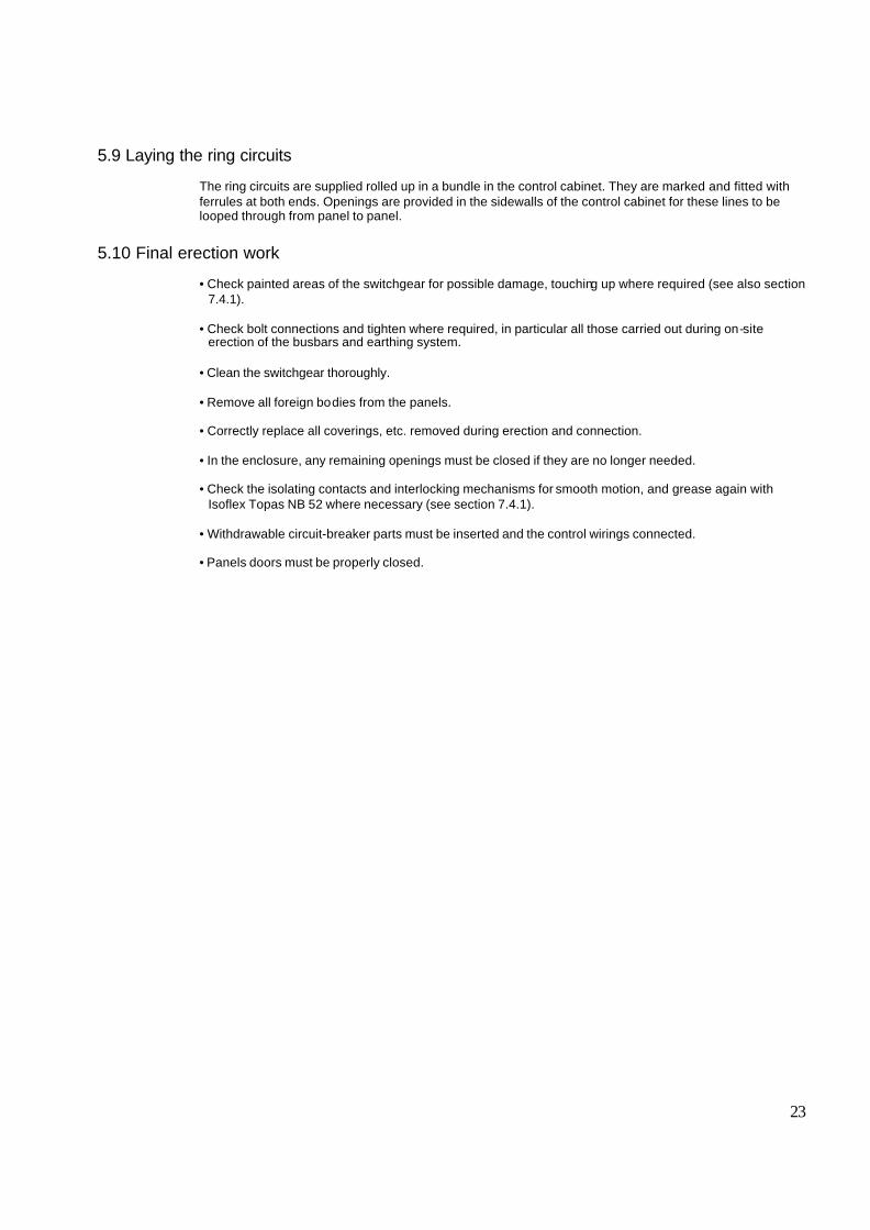
Figure 5/6: Removable ventilated roof element 1.7 Ventilation openings 1.8 Fixing bolts ( 6 pcs)
Figure 5/4: Bolting the switchgear panels together
Figure 5/5: Shematic diagram of the pressure relief duct. The components are assembled panel by panel and polted together 50 Exhaust channel on the top of cubicle
50

27
Figure 5/10-: 24 kV busbar element between two cubicles
1 12
Do not accept any cap or steps in theconnection of busbar and busbarelement
Figure 5/11 : Installation of bus bars between two cubicles 1 Busbars in the cubile 2 Busbar elements between two cubicles

28
1
2
3
4
Figure 5/13: View into the busbar compartment 1 Post insulator 2 Branch conductor 3 Busbar 4 End cover of busbar (EPDM rubber)
1
2
3
4
5
6
Figure 5/12-: Installation at bus bar ends
1266
86070
520
310
23
21
2421.1
Figure 5/14: Dimensions of power cable connection of UniSwitch 21 Cable clamp 21.1 Cable clamp when cable current
transformer (option) 23 Cable connection bar 24 Cable current transformer (option)
23
12.1
7
21
Figure 5/15: Partial view of the cable connection and cable entry
7 Main earthing bar 23 Cable connection bar 21 Cable clamp 12.1 Operating shaft fo r earthing switch

29
6. Operation of the switchgear
Note on safety at work
The relative work and operating procedure must be carried out carefully by trained specialist familiar with the installation, taking into account all the relative safety regulations according to the IEC and other relevant professional bodies, as well as any local and work regulations and instructions.
Note: Do not walk on the top surfaces of the switchgear panels (rupture points for pressure relief).
6.1 Commissioning
6.1.1 Preparatory work (Figures 3/8) In preparation for commissioning, the following work must be carried out prior to connection with the high voltage power supply: • Check the general condition of the switchgear for any damage or defects. • Visually inspect the switching devices, withdrawable parts, isolating contacts, insulating parts, etc. • Check connection of the main earthing bar to the installation earthing conductor (following the appropriate
safety regulations). • Check the paintwork for damage and, where necessary, touch up as described in section 7.4. • Remove all residues of materials, foreign bodies and tools from the switchgear. • Clean the switchgear, rubbing down insulating parts with a soft, dry, clean, non-fraying cloth. Remove any
greasy or sticky dirt as described in section 7.3. • Correctly remount all covers etc. removed during assembly and testing procedures. • Transport caps 13.9 on vacuum circuit breakers - if still fitted - must be removed. • Pole tube lids 13.10 on vacuum circuit breakers may be fitted in certain systems and on certain circuit
breakers. Check that they are fitted correctly. • Lifting eyebolts 13.13 on high current vacuum circuit breakers must be removed if still fitted. • Preparatory works for SF6 circuit breakers:
- Clean the insulating parts with clean dry cloth. - Check that the upper and lower terminals are clean and free of any deformation caused by shocks
received during transport and storage. - It is advisable to check the SF6 gas pressure.
• Switch the auxiliary and control voltage on. • Carry out testing operations on switching devices manually or by electrical control, and simultaneously
observe the relative position indicators. • Check mechanical and electrical interlocks for effectiveness, without using force. • Set the protective devices in the switchgear to the required values and check their function with test
equipment.

30
To check: • For any other matters regarding operation of the withdrawable circuit-breaker part and testing facilities for
the withdrawable part, see section 7.5. • Instruct local operators regarding the basic details of regular handling of the switchgear. • Check readiness for operation and switching status of electrical systems upstream and downstream of the
switchgear. Depending on allocation of responsibilities, it may also be necessary to check the following equipment in areas adjacent to the switchgear: • power cables • auxiliary cables • auxiliary power source • remote control system
• complete earthing system • switchroom equipment
• switchroom conditions
6.1.2 Start-up • Comply with all relevant safety regulations. • Ensure that the circuit breakers in the system are in the OFF position. • Remove any existing earthing and short circuiting connections in the critical switching area. • Energize the feeder cables. • Connect the switchgear step by step, observing the signals and indicators. • Check that relative conductors are in phase, where necessary, when there are several incoming feeder
cables and s witchgear sections (also see section 6.3.2). • Carry out all measurements and check all functions, which depend on high voltage power supply being
connected. • Watch out for irregularities of any kind.
6.2 Switching operations
Carry out switching operations with the front doors closed. 6.2.1 Withdrawable circuit-breaker part (Figures 3/10, 3/11, 6/2, 6/3) Manual insertion from the test/disconnected position to the service position: • Connect control wiring plug 10.2 • Close the front door. • Ensure that the circuit breaker is in the OFF position. • Fit hand crank 121 on square spigot 18.1 of the spindle mechanism 18, after opening the hole for them by
turning slide 121.1.

31
• Turn the crank clockwise approx. 20 turns until the stop is reached and the withdrawable part is in the service position.
• Observe the position indicator. • Remove hand crank 121. It must be considered that the spring loaded pin head 18.2 will lie completely on the rear side of the panel door when the hand crank is moved from square spigot 18.1 of spindle mechanism 18. This ensures that the rear part of the pinhead has been shifted onto the hexagonal cap of the spindle and prevents unintentional wrenching of the spindle during panel service. Wrenching may lead to the circuit breaker blocking. Note: The withdrawable part must not be stopped in any intermediate position in the travel range between the service and test/disconnected position!
Manual withdrawal from the service position into the test/disconnected position: • Ens ure that the circuit breaker is in the OFF position. • Reverse the procedure described above for insertion into the service position.
Important note: Insertion and withdrawal of circuit breakers (and other withdrawable parts) must be gradual, in order to avoid any shocks which could deform the mechanical interlock. If the operations are prevented, do not force the interlocks and check that the operating sequence is correct. The force normally applicable to the insertion/withdrawing lever is 260 N. In any case, the maximum applicable force must never exceed 400 N. Please also refer to the technical documentation of the circuit breakers for installation operations. Caution: the insertion and withdrawal must always be carried out with the circuit-breaker open! Do not use force to move withdrawable parts with locking magnet YO in the event of an auxiliary voltage drop. If this occurs, they are locked along the whole travel range between the service and test positions. To remove the interlock, consult the technical documentation of the circuit breakers.
Withdrawal from the test/disconnected position onto the service truck: • Open the door of the HV-compartment. • Release control wiring plug 10.2 and place it in the storage position on the withdrawable part. • Position service truck 124 with guide pins 124.2 of the adjustable bench top at the correct height facing
the panel front, and allow catch 124.3 to engage. • Move sliding handles 13.11 inwards against the springs to release withdrawable part 13, draw the
withdrawable part out onto the service truck and secure it in the catches on the truck. • Press release lever 124.4 (at the front underneath the bench top) and release the service truck from the
switchgear panel.
Insertion from the service truck into the test/disconnected position: • Carry out the procedure described above for withdrawal in reverse order.

32
6.2.2 Circuit-breaker - type VD4 (Figures 6/1) Charging the stored energy spring system: • On the circuit breaker with charging motors , charging is carried out automatically. If the charging motor
should fail, the charging procedure can be carried out or completed manually. • On breakers with manual charging systems, open the door with the withdrawable part in the disconnected
position, insert charging lever 128 into the recess and pump for approx. 25 strokes until the charged condition is indicated. When the charged condition is reached, the charging mechanism is automatically disengaged, and any further strokes of the lever have no effect.
Opening and closing the VD4 type circuit breaker: • Opening and closing operations with the withdrawable part in the service position should only be
performed with the door closed. • Operate the local or remote electrical control. • Observe the switch position indicator. The switching operation counter 13.5 for the circuit breaker automatically increases by one unit with each operating cycle. An additional control mechanism fitted in the door of the circuit-breaker compartment enables mechanical operation of the circuit breaker with the door closed and with the withdrawable part in either position (figures x/xx). • Press the relative mechanical pushbutton, having previously turned knob 45.2 anti-clockwise to the stop if
the withdrawable part is in the service position. • Observe the switch position indicator. For further details regarding operations and maintenance of VD4 circuit breakers, see instruction manuals BA 352 and BA 359.
6.2.4 Circuit-breaker - type HD4 (Figures 6/8) Manual operation for spring charging: To manually charge the closing springs, fully insert charging lever 90.8 into seat 90.6 and turn it until the yellow indicator 90.7 appears. Electrical operation for spring charging: On request, the circuit breaker can be fitted with the following accessories for electrical operation: • geared motor for automatic charging of the closing springs • shunt closing release • shunt opening release The geared motor automatically recharges the springs after each closing operation until the yellow indicator 90.7 appears. Should there be no voltage during charging, the geared motor stops and then starts recharging the springs automatically when the voltage is on again. In any case, it is always possible to complete the charging operation manually. Circuit-breaker closing: This operation can only be carried out with the closing springs completely charged. For manual closing press pushbutton 90.3. When there is a shunt closing release, the operation can also be carried out by means of a control circuit. The indicator 90.4 shows that closing has been accomplished.

33
Circuit-breaker opening: For manual opening, press pushbutton 90.2. When there is a shunt opening release, the operation can also be carried out with remote control by means of a control circuit. The indicator 90.4 shows that opening has been accomplished. An additional control mechanism fitted in the door of the circuit-breaker compartment enables mechanical operation of the circuit-breaker with the door closed and with the withdrawable part in either position (figures 3/14, 3/15 and 6/8). • Press the relative mechanical pushbutton, having previously turned knob 45.2 anti-clockwise to the stop, if
the withdrawable part is in the service position. • Observe the switch position indicator. Detailed information about installation and maintenance can be found in instruction manual 647016.
6.2.7 Earthing switch - type EM (Figures 6/11) The earthing switch - type EM - has a snap closing mechanism, which is independent of the rotation of the drive shaft. An earthing switch 5 allocated to a circuit-breaker is only enabled for switching when withdrawable part 11 is in the test/disconnected position or removed from the switchgear panel. Only turn earthing switches on when the door is closed. Auxiliary switch (Figure 3/13) The position of earthing switch can be indicated electrically by means of auxiliary switch. The auxiliary switch has been fixed on same mounting plate as earthing switch and connected mechanically by a lever to the main shaft of earthing switch. Manual opening and closing: • Press slide 14.2 onto the operating lever recess socket downwards. (When the switch is closed, it is already in this position!)
Caution! If the operation is prevented, do not force the interlock and check that the operation sequence is correct. • Fit operating lever 122 onto shaft 14.1,which is now released for operation.
Note: Put operating lever 122 on the shaft so that there is sufficient room for movement of the operating lever even if space is limited at the sides. • Turn the lever clockwise through approx. 180° until the stop is reached to close the earthing switch, or
anti-clockwise until the stop is reached to open the earthing switch. • Observe the mechanical/electrical switch position indicator. • Remove operating lever 122. Slide 14.2 remains open if the earthing switch is in the closed position. Make sure that the operating lever is turned right up to the stop in the opening process, to ensure that the earthing switch is in its defined limit position. The manual operating mechanism can also be fitted with a locking magnet.

34
6.3 Test procedure
6.3.1 Testing the off-circuit condition (Fig.) If the panels are equipped with capacitive voltage indication, checking the off-circuit condition can be carried out by means of this device. In this case, proceed according to the manufacturer’s instructions or the indicators. In case of any doubt about correct operation of capacitive voltage indication, the off-circuit condition must be checked using a HV tester. Checking the off-circuit condition must always be carried out in compliance with the relevant safety regulations and local operating conditions!

35
121
Figure 6/3: Movement of the withdrawable part between the test/disconnected position and the service position, clockwise up to the stop to the to the service position and anti-clockwise for the test/ disconnected position 121 Hand crank
10.1 10.2
32
Figure 6/2: Connect and release of control wiring plug interlock 10.1 Control wiring socket 10.2 Control wiring plug 32 Interlock
Figure 6/4: Handling of the mechanical circuit-breaker operation in the switchgear panel door (nonstandard equipment) with the withdrawable part in the service position 45.1 Mechanical pushbutton 45.2 Knob
128
13.8
13.2
13.5
13.4
13.11
Figure 6/1: Manual operation of withdrawable part with VD4 circuit-breaker 13.2 Mechanical OFF push-button 13.4 Mechanical operating cycle counter 13.8 Charging condition indicator 13.11 Sliding handle, connected with the catch on
the withdrawable assembly 128 Charging lever

36
90.8
90
Figure 6/8: Manual charging of HD4 circuit-breaker springs. 90 SF6 circuit-breaker type HD4 90.8 Charging lever
124 13 13.11
Figure 6/5: Service truck engaged with the switchgear panel. Withdrawable part released for withdrawal with the handles slid inwards 13 Withdrawable part 13.11 Sliding handle 124 Service truck
13
13.11
124.4
13.12 124.1 124 Figure 6/6: Withdrawable part standing on service truck and secured in the catches 13 Withdrawable part 13.11 Sliding handle 13.12 Catch (connected to sliding handle (13.11) 124 Service truck 124.1 Height adjuster 124.4 Release lever for catch pin (124.3)
124.2
124.3
124.1
Figure 6/7: Positioning the service truck with the guide pins on the adjustable height bench top at the correct height for approach to the switchgear panel, and engaging the catch 124.1 Height adjuster 124.2 Guide pin 124.3 Catch pin

37
125 Figure 6/12: Voltage indicator, placed on door of control cabinet. It is possible to use two types of Indicators. 125 Voltage indicator
14.1
14.2
Figure 6/10: Preparation for operation of branch earthing switch - press the slide downwards. 14.1 Shaft of earthing switch operating mechanism 14.2 Slide
122
122.1
Figure 6/11: Preparation for opeartion of branch earthing switch – operating lever prepared for switching on/off 122 Operating lever 122.1 Position indicator
Figure 6/9: View into the circuit-breaker compartment 10.1 Control wiring socket 12.1 Top shutter 12.2 Lower shutter 14 Earthing switch operating mechanism 14.1 Drive shaft 42 Right-hand travel rail 43.3 Duct cover, top right

38
Figure 6/13: Operating accessories 90.8 Charging lever (for HD4 type circuit-breaker) 121 Hand crank (for moving the withdrawable part inside the panel) 122 Operating lever (for earthing switch) 128 Charging lever (for HD4 type circuit-breaker) 124 Service truck

39
7. Maintenance 7.1 General
Maintenance serves to preserve trouble-free operation and achieve the longest possible working life of the switchgear. It comprises the following closely related activities: Inspection: Determination of the actual condition Servicing: Measures to preserve the specified condition Repair: Measures to restore the specified condition
Note: When carrying out all maintenance work, the regulations in the country of installation must be strictly complied with. Maintenance work may only be performed in a careful manner by trained personnel familiar with the characteristics of the individual switchgear, in accordance with all relevant IEC safety regulations and those of other technical authorities, and with other overriding instructions. It is recommended that ABB service personnel be called in to perform the servicing and repair work detailed below. The inspection and servicing intervals for some of the equipment/components (e.g. parts subjects to wear) are determined by fixed criteria, such as switching frequency, length of service and number of short-circuit breaking operations. On the other hand, for other parts the length of the intervals may depend, for example, on the different modes of operation in individual cases, the degree of loading, and also environmental influences (including pollution and aggressive air). The following operating instructions must also be followed, together with this instruction manual in the individual cases concerned: Air insulated metal enclosed switchgear: type UniSwitch 34M1 Vacuum circuit-breaker: type VD4 BA 352E SF6 circuit-breaker: type HD4 647016 If necessary, further details can be taken from the technical documentation for the switchgear installation (including, for example, any special operating conditions agreed on).
7.1.1 Intervals for inspection, servicing and repairs Time intervals for maintenance work to be carried out always depend on the operating conditions of the switchgear, and mainly on the mode of operation, the number of rated and short-circuit current switching operations, ambient temperature, pollution etc. We recommend carrying out the maintenance work at the following intervals:
Activity performed According to section Time interval in years According to number of switching operations
Inspection 7.2 4 1) Servicing 7.3 4 2) 10 000 3) Repair 7.4 As required As required
1) Under more demanding service conditions, we recommend shortening this interval appropriately – also sect. 7.1 and 7.2. 2) According to results of inspection. 3) See the instruction manual of the circuit breakers.

40
7.2 Inspection • Where necessary, the working area must be isolated and secured against reconnection in accordance
with the “Safety Regulations” specified by IEC and appropriate national standards before inspection. • Correct condition of the switchgear should be monitored by regular inspections. • Under normal operating conditions, inspection should be carried out once every four years by specially
trained professional electricians. • Under abnormal operating conditions (including adverse climatic conditions) and/or special environmental
stresses (heavy pollution and aggressive atmosphere, among others), inspection may be necessary at shorter intervals.
• Inspection is primarily to carry out a visual check for grime, corrosion and moisture:
- Effects of high temperature on the main circuits, - Traces of partial discharge on the insulating material parts, - Traces of leakage current on the insulating material parts, - Surfaces of the contact systems.
• However, inspection must also to include correct mechanical/electrical operation of the following parts:
switching devices, actuating, interlocking, and protection and signaling devices.
Special conditions:
Caution: instrument transformer circuit. • With regard to the switching devices, their separate Instruction manual should be followed. • Check all switchgear accessories and auxiliary devices (e.g. storage batteries). • No partial discharge must occur on the surfaces of equipment at operating voltage. This can, for example,
be detected by characteristic noises, a clearly perceptible smell of ozone, or visible glowing in the dark. • Visually checks the contact system. We recommend to turn the contact system alternately in order to
clean the inner contact points of the contact system. The contact points should be cleaned if signs of overheating (discolored surface) are visible (see, section
7.4). • If any irregular conditions are detected, then relative repair measures must be taken.
7.3 Servicing
If, during the course of an inspection in accordance with section 7.2, the need for cleaning measures has been established, proceed as follows: • Where necessary, the working area must be switched off and secured against reconnection in accordance
with the “Safety Regulations” specified by IEC and appropriate national standards before cleaning. • Clean the surfaces in general:
- Weakly adhering dry dust deposits: with a soft dry cloth. - More strongly adherent grime: with mildly alkaline household cleanser or with ETHANOL F 25 M.
• Clean insulating surfaces and conductive components with ETHANOL F 25 M. • Wipe down after cleaning, using clean water, and dry properly. • Should partial discharges occur as a result of condensation, application of a thin silicone film on the
surface concerned is often effective as a temporary remedy. It is advisable to ask the ABB after-sales service department for advice regarding permanent solutions to this type of unusual problem.

41
7.4 Repair
7.4.1 Switchgear in general Repair of surface damage: • Carry out repair work immediately after a defect has been discovered. • Completely remove all rust from damaged paintwork areas on steel sheet and other steel parts by
mechanical means, e.g. with a wire brush. • Lightly grind the surrounding paint coat and carefully degrease the entire area. Then immediately apply an
anti-rust primer and, after an appropriate hardening time, apply the top coat. Only use suitable and compatible paints products.
• Apply the topcoat in standard RAL 7035 color, or the relevant special color. • Carefully remove any white rust on aluminium/zinc surfaces with a wire brush or cleaning pad, e.g.
Scotch-Brite, and clean loosely adhering particles with a dry, non-fraying cloth. Next treat the cleaned parts with zinc spray or zinc powder paint and, finally, treat with aluminium spray for color matching.
• Carefully remove any white rust from passivated operating parts and rust formation on phosphatised parts
with a wire brush or metal-free cleaning pad, e.g. Scotch-Brite, and clean with a dry cloth. Then grease evenly (with Isoflex Topas NB 52).
Switchgear in general: • Follow the maintenance instructions in the manuals for individual equipment components. • Check that the bolt connections at the contact points in the busbar system and the earth connections are
tight, and that the contact system functions correctly. • Where necessary, grease slide plates and bearings in the panel again or thoroughly clean them. Then
grease them again with Isoflex NB 52 lubricant. • Top up grease on contact areas in the contact system when corroded or otherwise as necessary, or, when
lubrication is inadequate or missing, thoroughly clean the areas concerned and grease them again with Isoflex Topas NB 52 lubricant.
• Remove the contact system for thorough cleaning as described below (Figures 7/1, 7/3):
- Slide in the two inner ring tension springs 4.4 facing the breaker pole to a position beside the other two outer ring tension springs, thus releasing contact system 4.3, and remove the contact system. -The contact pin of the contact system and the slot on the contact arm must be cleaned and greased. Fit contact system back to front on the thin end of arbor 127 and slide it forwards onto the thicker part of the shank. - Fit arbor 127 onto the relative contact arm 4.2, slide the contact system 4.3 over onto the contact arm, and withdraw the arbor. - Check that all contact fingers and ring tension springs have a perfect fit.
Note: The set installation position of contact arms 4.2 must not be changed by undue use of force

42
Replacement of the contact pins when the surface is damaged: (Figure 3/11) After any required replacement of contact pins 4.1, the latter should be retighten using the socket head bolts.
Thread Rated tightening torque ungreased M10 46 Nm M20 250 Nm
7.4.2 Replacement of complex functional groups (Figures 3/3, 3/11, 7/3 to 7/11) Precise matching of functions for control, interlocking and signaling only permits replacement of individual components to a limited extent. The following assemblies are prefabricated and tested at the works, maintaining high quality standards. In the case of faults, they must therefore be completely replaced. 1. Withdrawable assembly: • Disconnect plug connector 10.3. • Remove interlock rod 13.91 with pin 13.27 from the withdrawable assembly. • Remove the circuit breaker from the withdrawable assembly (4 x M12 bolts). • Mount the circuit breaker on a new withdrawable assembly in th e reverse order, using new circlips and
special pliers for pin 13.27. • Check the setting of interlocking rod 13.91.
- Turn spindle 18 anti-clockwise to the stop for the disconnected position: The distance between lever 13.26 and cam 13.25 must be 2±1 mm. The distance between roller 13.24 and angle lever 13.92 must be 0.5 mm. - Turn spindle 18 clockwise to the stop for the service position: The distance between lever 13.26 and cam 13.25 must be 2±1 mm. The distance between roller 13.24 and angle lever 13.92 must be 0.5 mm. - Loosen bolts 13.91.2 or 13.92.1 for any necessary adjustment.
7.5 Testing withdrawable parts (Figures 7/3, 7/4)
When functional tests are carried out on withdrawable parts, compliance with the conditions listed below should also be checked.
7.5.2 Checking correctness of dimensional settings (Figures 7/3, 7/9, 7/10) 1. The distance between lever 13.26 operated by tie-rod 13.91 and plastic cam 13.25 should be 2±1 mm. If adjustment is required, loosen the two bolts 13.91.1 and 13.91.2. Deviations from the specified value can have the following effects: • Dimensions too large, locking system for the drive spindle deactivated. • Dimensions too small, proper action of the electrical interlock no longer guaranteed. 2. The distance between roller 13.24 and angle lever 13.92 should be 0.5 mm when the circuit breaker is
closed. If adjustment is required, loosen the two bolts 13.91.2 and 13.92.1.

43
7.5.3 Checking auxiliary switch settings on withdrawable parts (Figures 3/22, 7/3) Compliance with the interlock conditions in the test/disconnected and service position areas is ensured by position signaling switches S8 and S9 located in the withdrawable assembly and factory-set. During testing operations, the withdrawable part m ust be moved by hand with the crank fitted and with the motor power switched off. 1.Settings in the area of the test/disconnected position:
• Move the withdrawable part out of the test/disconnected position towards the service position with a few turns of the crank.
• Slowly move the withdrawable part back to the stop.
Auxiliary switch S8 must then switch over just before the stop is reached. • Slowly insert the withdrawable part from the test/disconnected position towards the service position until
auxiliary switch S8 just operates. In this position, it must still just be possible to move closing push rod 13.2.1. For this test, the function of
the locking magnet Y0 must be deactivated manually. This condition ensures that the electrical interlock takes effect before the mechanical interlock in the
motion sequence involved. 2.Settings in the area of the service position:
• Move the withdrawable part out of the limit position towards the test/disconnected position with a few turns of the crank.
• Slowly m ove the withdrawable part forward again to the stop. Auxiliary switch S9 must then switch over just before the stop is reached.
7.5.5 Testing interlock conditions (Figures 3/9, 3/22, 6/6 to 6/8, 7/7) 1. The withdrawable part must only be movable from the test/disconnected position into the service position
when the circuit breaker is open and the earthing switch is open.
Check the following conditions individually: • With the circuit breaker closed, insertion of the withdrawable part towards the service position must be
locked after only half a turn of the crank in the clockwise direction. • With the earthing switch closed, insertion of the withdrawable part towards the service position must be
locked after only two clockwise turns of the crank
Use no force! Also see the note in chapter 6.2.1! 2. The withdrawable part must only be movable from the test/disconnected position into the service position
when the control-wiring plug is inserted.
Check the following conditions individually: • With the control wiring plug disconnected, insertion of the withdrawable part towards the service position
must be locked after only half a turn of the crank in the clockwise direction. 3. The withdrawable part must only be movable from the service position into the test/disconnected position
with the circuit-breaker open. Check this condition as follows: • With the circuit breaker closed, withdrawal movement of the withdrawable part must be locked after only
half a turn of the crank in anti-clockwise direction. 4. Closing of the circuit breaker must only be possible when the withdrawable part is in the defined
test/disconnected position or service position.

44
The control-wiring plug 10.2 must previously have been inserted. Check this condition as follows: • It m ust not be possible to close the circuit breaker with the withdrawable part in any position between the
test/disconnected position and the service position. Enabling of switching when the withdrawable part moves into the service position is carried out electrically by operation of auxiliary switch S9 in the withdrawable assembly, and slightly earlier mechanically - this corresponds to a position approximately half a turn of the crank before the stop. • For movement into the test/disconnected position, the same enabling conditions apply in the same way, in
this case by means of auxiliary switch S8 in the withdrawable assembly. 5. It must only be possible to open the circuit breaker (manually) when the withdrawable part is in the
service position or test/disconnected position and the control voltage has failed. 6. Withdrawable parts with order-related locking magnet Y0 may not be moved in case of control power
failure, or when there is no control power. Do not forcibly move locked withdrawable parts! The locking magnet Y0 is only present on manually operated withdrawable parts.
Releasing the locking magnet Y0: • Remove front plate 13.17. • Disengage locking magnet Y0 by pulling the magnet armature, • While doing so, turn crank 121 about one half turn (either direction of rotation is permissible).
The locking magnet is only active in the test position and service position. In intermediate positions it has no effect.
7. Disconnection of the control-wiring plug 10.2 as well as later insertion must be locked in the withdrawable
part service position. 8. Operation of the earthing switch must only be possible when withdrawable part 13 is in the
test/disconnected position or the removed position (subject to any additional electro-magnetic interlock in individual cases).
Check this condition: • With the withdrawable part in the test/disconnected position, it must be possible to press slide 14.2, in
front of the earthing switch operating shaft 14.1, downwards to the opening position. The earthing switch can then be operated.
• If the slide is pressed down slightly when the travel motor is running, the motor must then automatically
switch off immediately. Pressing the button continues the selected travel direction. • When the withdrawable part is moved inwards towards the service position, pressing down of slide 14.2
must be locked after only one and a half clockwise turns on the crank.

45
7.6 Tests on the panel 7.7 Spare parts, auxiliary materials and lubricants
7.7.1 Spare parts A spare parts list is available on request for procurement of spare parts. It basically includes moving parts and parts subject to wear. When parts are required, the serial number of the relative switchgear or switching device should always be quoted.
7.7.2 Auxiliary materials, lubricants Lubricant: • Isoflex Topas NB 52
Halogen-free cleansers: • ETHANOL F 25 M (for general cleaning)
Touch-up paint: Standard colour RAL 7035
Figure 7/10: Mechanical interlock, withdrawable assembly/ VD4 type circuit-breaker, with manually operated withdrawable part 13.24 Roller 13.25 Plastic cam 13.26 Lever 13.27 Pin 13.91 Tie- rod 13.91.1 Bolt 13.91.2 Bolt 13.92 Angle lever 13.92.1 Bolt
46
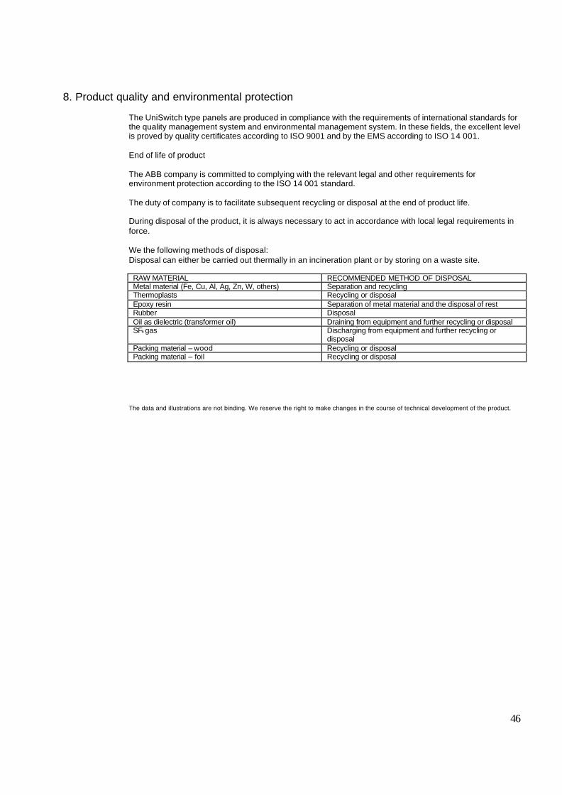
8. Product quality and environmental protection
The UniSwitch type panels are produced in compliance with the requirements of international standards for the quality management system and environmental management system. In these fields, the excellent level is proved by quality certificates according to ISO 9001 and by the EMS according to ISO 14 001. End of life of product The ABB company is committed to complying with the relevant legal and other requirements for environment protection according to the ISO 14 001 standard. The duty of company is to facilitate subsequent recycling or disposal at the end of product life. During disposal of the product, it is always necessary to act in accordance with local legal requirements in force. We the following methods of disposal: Disposal can either be carried out thermally in an incineration plant or by storing on a waste site.
RAW MATERIAL RECOMMENDED METHOD OF DISPOSAL Metal material (Fe, Cu, Al, Ag, Zn, W, others) Separation and recycling Thermoplasts Recycling or disposal Epoxy resin Separation of metal material and the disposal of rest Rubber Disposal Oil as dielectric (transformer oil) Draining from equipment and further recycling or disposal SF6 gas Discharging from equipment and further recycling or
disposal Packing material – wood Recycling or disposal Packing material – foil Recycling or disposal
The data and illustrations are not binding. We reserve the right to make changes in the course of technical development of the product.