Embed Size (px)
Citation preview

WLANIndoor Radio Network planning
Laselva [email protected]
1 April 2003
Access point
Air interface
Wireless L AN cardSTA

S-72.333 WLAN-Indoor NT planning/ Laselva 2
Outline• WLAN general issues
• Wireless network topologies
• IEEE 802.11 layers� ���
� ����� ����� � �� ����������� ����
� ���� ������������� �!����"�#�$"�����%���
• Radio indoor propagation
• Network Planning for IEEE 802.11 WLAN
• Security
• Comparison with 3G systems
• References

(Wireless LAN) WLAN• Mobility
– In usage scenarios:• Ah Hoc NTs• Public Access Zones: campus areas, airports, hotels• Small office and home (SHO)• Enterprices and Brach offices: all the applications used through the WLAN
• Installation– Less cabling– Wireless LAN can easily be moved to other location
• Costs– Installation costs may be lower– Saves when the LAN needs moving
• Scalability– Ad hoc networks– From one cell to multiple cell networks
• Spread Spectrum techniques to improve spectral efficiency• Evolution toward All-IP core network architectures already def:
Perspective of UMTS-WLAN deployment: combine nationwide mobility with 3G networks and hot spot coverage withWLANs:
– complementary coverage and greater bandwidth• WLAN max connection range 100 m (300 m in outdoor)• 802.11b: 2,4 GHz with connection speeds reaching 11 Mbps• 802.11a: 5 GHz with connection speeds reaching 54 Mbps
S-72.333 WLAN-Indoor NT planning/ Laselva 4
�������&'�(��)��*
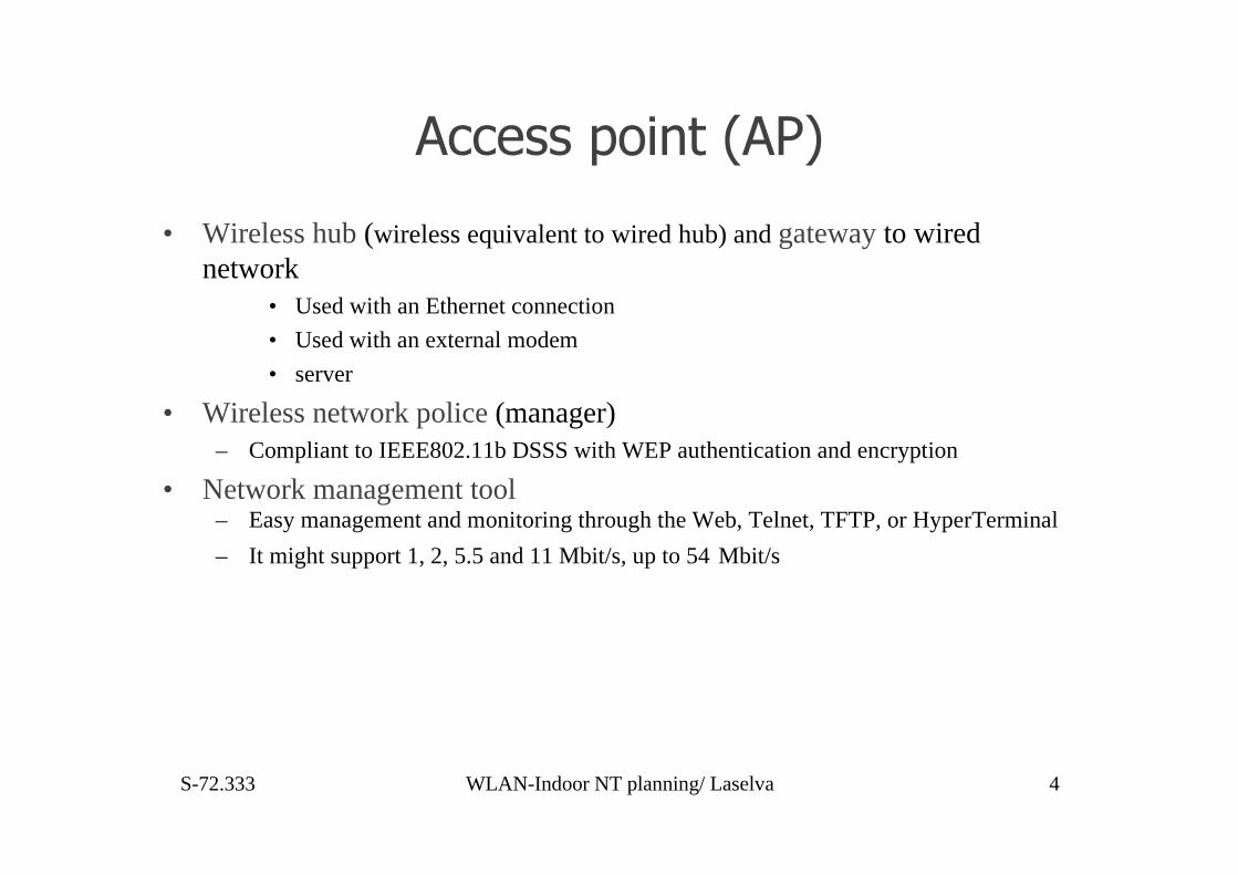
• Wireless hub (wireless equivalent to wired hub) and gateway to wirednetwork
• Used with an Ethernet connection
• Used with an external modem
• server
• Wireless network police (manager)– Compliant to IEEE802.11b DSSS with WEP authentication and encryption
• Network management tool– Easy management and monitoring through the Web, Telnet, TFTP, or HyperTerminal
– It might support 1, 2, 5.5 and 11 Mbit/s, up to 54 Mbit/s

+� �!����(���' ,��'&'!'����
Ad hoc (peer-to-peer) networks:• Formed by wireless stations• No AP needed• Enables file and printer sharing
Infrastructure networks:• Formed by an AP and wireless stations• All communication via the AP• The AP can be attached to a wired LAN,and wireless stations communicate with wired stations
LAN
ACCESSPOINT
ACCESSPOINT
L aptop-to-
laptopconnec
tion

S-72.333 WLAN-Indoor NT planning/ Laselva 6
Multiple access pointsStandard identifies basic message format to support roaming (implementation for NT vendors):– when current AP connection lost– when better AP available (roaming calculation): STA scans adjacent channels (Aps in
ESSIDs)Used to extend the range of a network or increase capacity, two ways presented:
– Same network name and on the same subnet (on the same LAN): intra subnetroaming:
– Stations can roam with the same network name– Roaming is transparent to the user - it is automatic– Must be on same TCP/IP subnet
– Different network name but on the same LAN: different logical networks
ACCESSPOINT
LAN
WirelessL AN 2
WirelessL AN 1
ACCESSPOINT
ACCESSPOINT

S-72.333 WLAN-Indoor NT planning/ Laselva 7
---��� ����!�.� �
• IEEE 802.11 is a wireless extension of IEEE 802 LAN standard family– shares the same Logical Link Control (LLC) layer with other fixed LAN standards
(e.g.IEEE 802.3 Ethernet)
• IEEE 802.11 standard defines:– Physical (PHY) layer
– Medium access control (MAC)
– For both specification for wireless connectivity in the local area for• Fixed
• Portable
• or moving stations
S-72.333 WLAN-Indoor NT planning/ Laselva 8
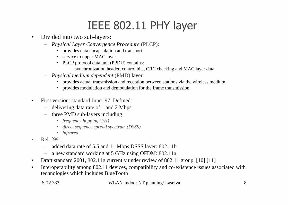
---��� ��������!�.� • Divided into two sub-layers:
– Physical Layer Convergence Procedure (PLCP):• provides data encapsulation and transport• service to upper MAC layer• PLCP protocol data unit (PPDU) contains:
– synchronization header, control bits, CRC checking and MAC layer data
– Physical medium dependent (PMD) layer:• provides actual transmission and reception between stations via the wireless medium• provides modulation and demodulation for the frame transmission
• First version: standard June ´97. Defined:– delivering data rate of 1 and 2 Mbps– three PMD sub-layers including
• frequency hopping (FH)• direct sequence spread spectrum (DSSS)• infrared
• Rel. ´99– added data rate of 5.5 and 11 Mbps DSSS layer: 802.11b– a new standard working at 5 GHz using OFDM: 802.11a
• Draft standard 2001, 802.11g currently under review of 802.11 group. [10] [11]• Interoperability among 802.11 devices, compatibility and co-existence issues associated with
technologies which includes BlueTooth

�� ������/$�(����& ��#��&��� $"��.���"• PPDU (protocol data unit) frame structure of the PLCP
– Preamble fields for receiver synchronization– Header fields contain control information– MPDU is actual data from the upper layer
• DSSS channels– standard specifies the operation of DSSS on 14 channels of different frequency– each channel have 22 MHz bandwidth with central frequency of each channel
• channels are overlapping:– only three channels can work together without adjacent channels interference (e.g. 1, 6, and 11)
• DSSS Modulation– For 1 and 2 Mbps data transmission, the 11-chip Barker code is used for spectrum spreading– BPSK or QPSK modulation is carried to the base-band data respectively.
• An 11 Mcps base-band signal (1 Mbps data times 11 for chip spreading) will occupy 22 MHz bandwidth using BPSKmodulation.
• A 22 Mcps signal (2 Mbps data times 11 for spreading) will occupy 22 MHz bandwidth using QPSK modulation.
– For 5.5 and 11 Mbps data transmission, spreading scheme: Complementary Code Keying (CCK):• M-ray orthogonal keying modulation where one of the M’s unique signal code words is chosen for txm
• 5.5 Mbps txm: 4 bits grouped together, two used to decide the phase. Another two bits are used toselect one from four complex code sequences.
– The symbol rate is 1.375 Mbps and the occupied bandwidth is 22 MHz.
• 11 Mbps txm: 8 bits grouped together.– The first two the same as in 5.5 Mbps– The left 6 bits are used to select one complex code from 64 combinations.
» the symbol rate is 1.375 Msps and bandwidth is 22 MHz
• 4 types of DSSS models interoperable, share same preamble, header structure, same radio BW• Preambles and headers are modulated at 1 Mbps rate (differences in modulation rate only to MPDU)
Channel No. 1 2 3 4 5 6 7
Central Freq. (GHz) 2.412 2.417 2.422 2.427 2.432 2.437 2.442
Channel No 8 9 10 11 12 13 14
Central Freq. (GHz) 2.447 2.452 2.457 2.462 2.467 2.472 2.484
S-72.333 WLAN-Indoor NT planning/ Laselva 10
����& ��#��&��� $"��.���"• IEEE 802.11 defines FHSS PMD layer to deliver:
– 1 Mbps and 2 Mbps data rate in 2.4 GHz band.• PPDU packet structure:
– Preamble: provides frame self-synchronisation– Header: provides control functions
• FHSS channel:– In Europe, USA, runs on 79 channels, from 2.402 GHz to 2.480 GHz.– channel spacing is 1MHz– 78 hopping sequences defined
• in each sequence each of the 79-frequency elements is used once.• minimum frequency spacing in one hopping sequence is 6 MHz.• Three subsets are defined from 78 sequences with 26 for each.
• For minimizing interference � different cells use sequences from different subsets– IEEE 802.11 standard didn’t specify the hop rate:
• United States, 2.5 hops per second is the minimum requirement.• Japan, France, and Spain have defined a different number of channels and sequences for the FHHS mode.• the hop space and the hop rate may differ in different countries.
• Two different modulation methods defined for 1 and 2 Mbps date rates
– 1 Mbps:two-level Gaussian frequency shift key (GFSK) with BT=0.5 modulation used. Nominal frequencydeviation is +/- 160 KHz.
– 2 Mbps: four level GFSK with BT=0.5 used. Four frequency deviations are +/- 216 KHz and +/- 72 KHz.
S-72.333 WLAN-Indoor NT planning/ Laselva 11
Infrared system
• The IEEE 802.11 infrared (IR) PHY layer uses:– pulse position modulation to transport 1 Mbps and 2 Mbps data rates using
infrared light
– It is limited to the LOS transmission or a single reflection environment
– IR frame has the structures similar to the FHSS or DSSS system. So farthere is no IR based WLAN product shown on the market.
• IR frame has the structures similar to the FHSS or DSSS system
• So far there is no IR based WLAN product shown on the market
S-72.333 WLAN-Indoor NT planning/ Laselva 12
�� ����• Use Orthogonal Frequency Division Multiplexing (OFDM) method to deliver
– up to 54 Mbps data rate in 5 GHz band: band belongs to the Unlicensed National Information Structureband (UNII).
– Twelve sub-channels are defined and each channel has a 20 MHz bandwidth.– Eight different data rates are supported: 6, 9, 12, 18, 24, 36, 48, 54 Mbps.
• For each sub-channel the OFDM system uses 52 sub-carriers that are modulated by using:– BPSK,– QPSK,– 16-QAM,– or 64-QAM, depending on the data rate
• Use Convolutional coding with rates 1/2, 2/3 or 3/4 for forward error correction– trade-off between data rate and coverage range.
• e.g at 6 Mbps, the receiver sensitivity is –82 dBm;• at 54 Mbps, the receiver sensitivity is –65 dBm.
• The IEEE 802.11a standard is not compatible with the 802.11 or 802.11b standard• PLCP frame structure of ODFM PMD:
– Preamble contains 12 symbols for channel estimation and frame synchro (16 microseconds length)– Signal part, including length, parity check and tail field is 24 bits.– It is convolution-coded with 1/2 rate and then modulated to one OFDM symbol using BPSK. Service
field, PSDU and other fields are modulated to OFDM symbols using different coding and modulationmethods.
S-72.333 WLAN-Indoor NT planning/ Laselva 13
Orthogonal frequency division multiplexing(OFDM)
• A multicarrier communication system in which the frequency band (availablespectrum) is composed of a number of narrowband carriers
– Modulation and coding methods at different data rates association standardised
– Each OFDM channel divided into 52 sub-carriers• 48 used to carry data (working in parallel)
• 4 carriers used as pilot channels, frequency references
– A pseudo-binary sequence is sent through the pilot channel to prevent the generation of the spectral line.
• Each carrier (a separate band frequency) is modulated with a symbol and multiplexedwith other carriers:
– Data is divided into parallel data streams each transmitted on an narrowband carrier.
• The carriers are modulated and demodulated using the Inverse Fast FourierTransform (IFFT) and Fast Fourier Transform (FFT) in OFDM transmitters andreceivers: sin(x)/x spectra for subcarriers:
– symbol duration is 4 microseconds --> occupied BW= 16.6 MHz.
• Great advantage: excellent spectral efficiency due to the close spacing because of themutual orthogonality of the carriers �FFT operation creates carriers with sidebandsthat overlap with no mutual interference
S-72.333 WLAN-Indoor NT planning/ Laselva 14
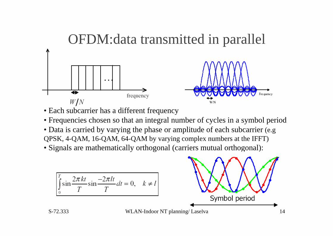
OFDM:data transmitted in parallel
• Each subcarrier has a different frequency• Frequencies chosen so that an integral number of cycles in a symbol period• Data is carried by varying the phase or amplitude of each subcarrier (e.gQPSK, 4-QAM, 16-QAM, 64-QAM by varying complex numbers at the IFFT)• Signals are mathematically orthogonal (carriers mutual orthogonal):
S-72.333 WLAN-Indoor NT planning/ Laselva 15
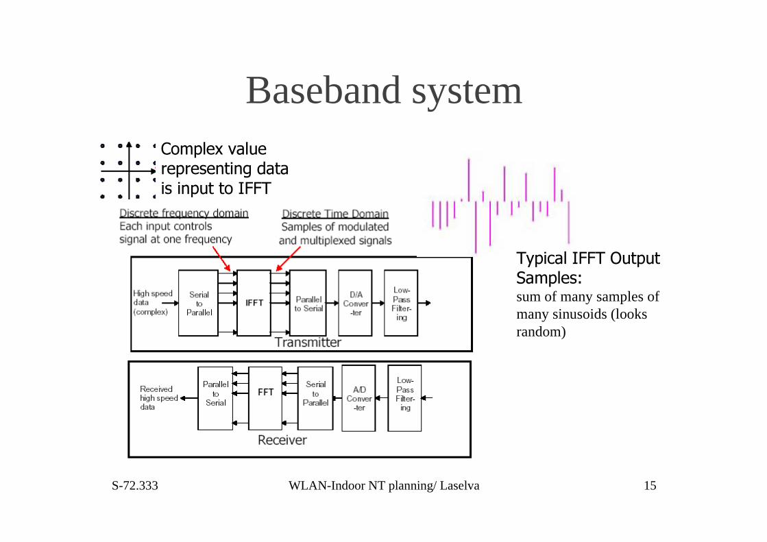
Baseband system
0.&���!���0��$�&$���"&!��1sum of many samples ofmany sinusoids (looksrandom)
�'"&!�2�3�!$� �& ���(��(��#�������(&$���'���0
S-72.333 WLAN-Indoor NT planning/ Laselva 16
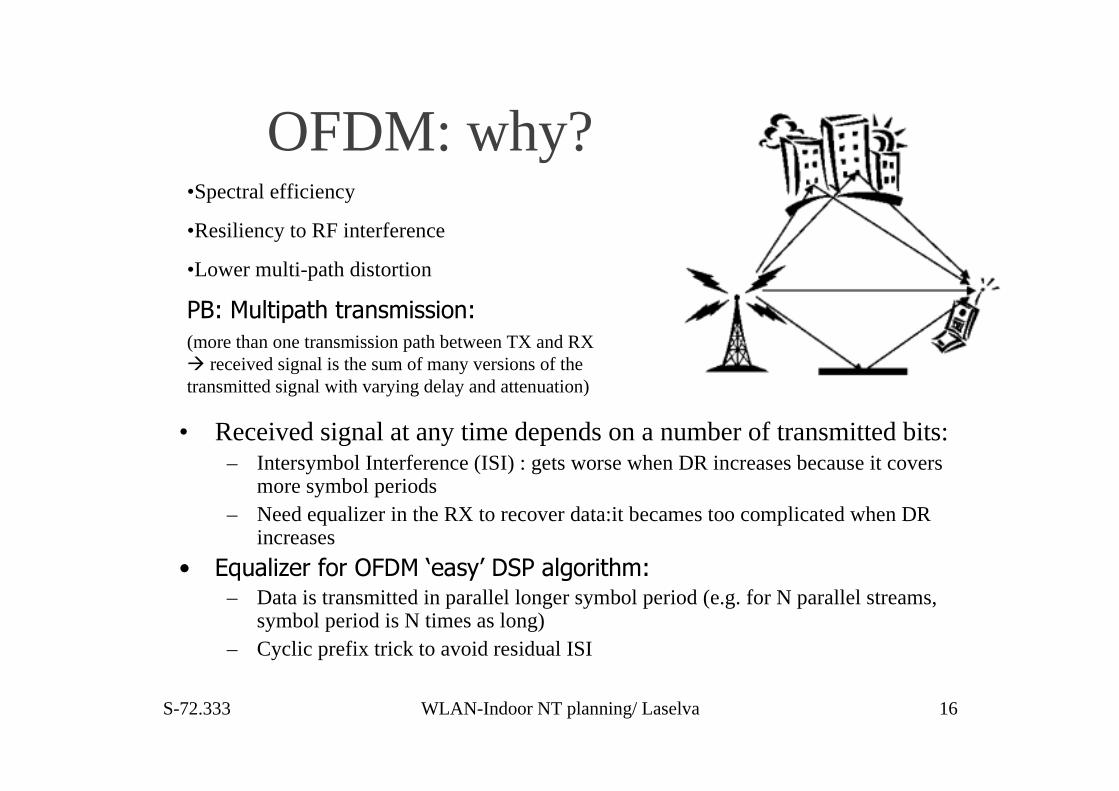
OFDM: why?
• Received signal at any time depends on a number of transmitted bits:– Intersymbol Interference (ISI) : gets worse when DR increases because it covers
more symbol periods– Need equalizer in the RX to recover data:it becames too complicated when DR
increases
� -/$�!�4� �5' ������6���.7������!�' ���"1– Data is transmitted in parallel longer symbol period (e.g. for N parallel streams,
symbol period is N times as long)– Cyclic prefix trick to avoid residual ISI
•Spectral efficiency
•Resiliency to RF interference
•Lower multi-path distortion
�81��$!��&����� �(�"����'(1(more than one transmission path between TX and RX� received signal is the sum of many versions of thetransmitted signal with varying delay and attenuation)

S-72.333 WLAN-Indoor NT planning/ Laselva 17
�$!��&�����(3� '"�(���(#��.�!���� �5�2
• Received signal (one subcarrier) in onesymbol period is not a sinusoid:
•Causes intercarrier interference (ICI)
•Each symbol is cyclically extended:•Some loss in efficiency as cyclic prefixcarries no new information
•If multipath delay is less than the cyclicprefix:
•no intersymbol or intercarrier interference•amplitude may increase or decrease

� �/$�(�.���!����3��5�#�(�
•Multipath fading causes some frequencies to beattenuated:
•Fading is approximately constant over narrow band•This is corrected in the receiver
•Multipath delay causes change in amplitude andphase of each subcarrier
•Change depends on subcarrier frequency•Corrected in receiver by one complex multiplicationper subcarrier
• Multipath fading corrected by single tap equalizer
•Change in phase and amplitudecorrected by complex multiplication•Receiver structure suited to DSPimplementation
S-72.333 WLAN-Indoor NT planning/ Laselva 19
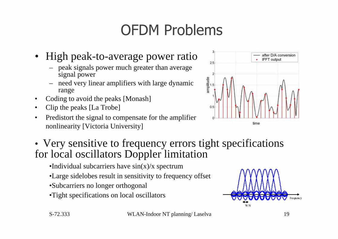
������ '�!�"�
• High peak-to-average power ratio– peak signals power much greater than average
signal power– need very linear amplifiers with large dynamic
range• Coding to avoid the peaks [Monash]• Clip the peaks [La Trobe]• Predistort the signal to compensate for the amplifier
nonlinearity [Victoria University]
• Very sensitive to frequency errors tight specificationsfor local oscillators Doppler limitation
•Individual subcarriers have sin(x)/x spectrum•Large sidelobes result in sensitivity to frequency offset•Subcarriers no longer orthogonal•Tight specifications on local oscillators
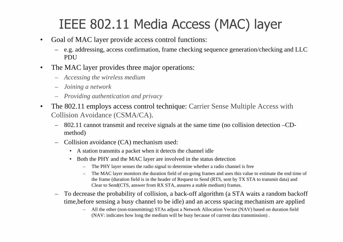
---��� ������#����������)���*�!�.� • Goal of MAC layer provide access control functions:
– e.g. addressing, access confirmation, frame checking sequence generation/checking and LLCPDU
• The MAC layer provides three major operations:– Accessing the wireless medium
– Joining a network
– Providing authentication and privacy
• The 802.11 employs access control technique: Carrier Sense Multiple Access withCollision Avoidance (CSMA/CA).
– 802.11 cannot transmit and receive signals at the same time (no collision detection –CD-method)
– Collision avoidance (CA) mechanism used:• A station transmits a packet when it detects the channel idle
• Both the PHY and the MAC layer are involved in the status detection– The PHY layer senses the radio signal to determine whether a radio channel is free
– The MAC layer monitors the duration field of on-going frames and uses this value to estimate the end time ofthe frame (duration field is in the header of Request to Send (RTS, sent by TX STA to transmit data) andClear to Send(CTS, answer from RX STA, assures a stable medium) frames.
– To decrease the probability of collision, a back-off algorithm (a STA waits a random backofftime,before sensing a busy channel to be idle) and an access spacing mechanism are applied
– All the other (non-transmitting) STAs adjust a Network Allocation Vector (NAV) based on duration field(NAV: indicates how long the medium will be busy because of current data transmission) .

������������� �!����"�#�$"�)����%���*• Before transmitting a frame, the MAC layer has to gain control of radio resource. Two
approaches are used:– Distributed Co-ordination Function (DCF):
• radio resource is competed by all stations with no master control• With the random back-off mechanism and access spacing interval, the probability of collision can be
minimized. Using handshaking methods, for example by sending Request To Send (RTS), Clear ToSend (CTS) frames, the “hidden node” problem can be eliminated.
– Point Co-ordination Function (PCF):• a point co-ordinate resides in the access point (AP) to control the transmission• Every station needs to be granted the right to send before it can send any packet• No contention check occurs at the centralized control• An option in the 802.11 standard � not all vendors support this option.
9'�(�(������(���' ,• Once one client station (STA) is powered on, it needs to search passively or actively for theexistence of:
•other STAs
•or Access Points (AP)
•If any authentication result is successful, this STA can join the network and communicate with others.
����!�.� �5 �"���� $��$ �• Compatible with other IEEE 802.x MAC protocol.
• There are three types of frames:
• Management frames: handle the functions of Association, Authentication, Probe, and Beacon
• Control frames: handle Handshaking, Acknowledgement, Power control, etc
• Data frames: carry the data package from the upper layer (LLC).

S-72.333 WLAN-Indoor NT planning/ Laselva 22
Indoor Radio propagationBasic propagation phenomena:
--> manifest themselves in signal attenuation and delay
1. Electromagnetic wave impinges upon an obstruction with dimensions very large compared with thewavelength of a radio wave
•A part of the energy is reflected back to the first medium by obeying Maxwell’s Equations and boundary conditions
•if the second medium is a perfect conductor all incident energy will be reflected back: total reflection
•if perfect dielectric plane another part of the energy is transmitted into the second medium: penetration
1. Reflection
2. Diffraction
3. Scattering
2. Radio path is obstructed between the transmitter and receiver by some impenetrable object with a sharp edge.•explained by the Huygen’s principle
•can transfer the signal energy to the receiver even if no Light of Sight (LOS) route exists between transmitters and receivers.
3. Radio channel contains objects with dimensions that are of the same order, or less as the radio wavelength.•Radio energy is re-radiated in many other directions
•diffuses or diminishes some part of the reflection energy
•positive effect of scattering is that it brings some energy to the receiver where normal reflected or diffracted signal can not reach

S-72.333 WLAN-Indoor NT planning/ Laselva 23
Propagation parameters
1.Link budget– how far the TX and RX can be separated?
– depends on many aspects:coverage, interference, transmitter power and battery life)
– needs an estimation of the Signal to Noise Ratio (SNR) and path loss
2.Time dispersion (Multipath delay spread)– due to the Multipath structure existing between the TX and RX:
transmitted signal and its delayed versions arrive at the RX at different time instant
– it causes Inter Symbol Interference (ISI): times disperse nature of radio channel limitsthe maximum data transmission rate without utilising an equalizer at the receiver.
– varies widely in mobile radio channels: power delay profile P(τi) used to characterizethe power distribution of the multi-path signals (τi is an excess delay of the i-thelement) (Several delay spread definitions)
S-72.333 WLAN-Indoor NT planning/ Laselva 24
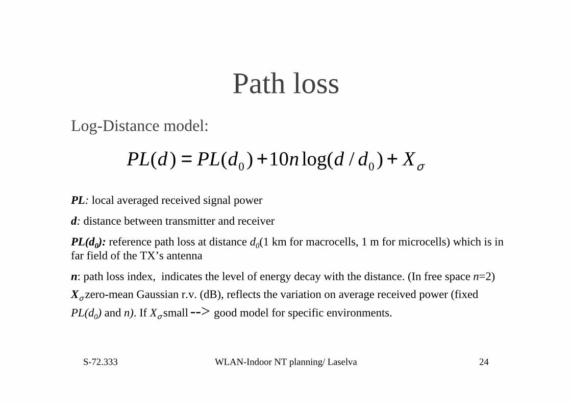
Path loss
0 0( ) ( ) 10 log( / )PL d PL d n d d Xσ= + +
Log-Distance model:
PL: local averaged received signal power
d: distance between transmitter and receiver
PL(d0): reference path loss at distance d0(1 km for macrocells, 1 m for microcells) which is infar field of the TX’s antenna
n: path loss index, indicates the level of energy decay with the distance. (In free space n=2)
Xσ zero-mean Gaussian r.v. (dB), reflects the variation on average received power (fixed
PL(d0) and n). If Xσ small --> good model for specific environments.
S-72.333 WLAN-Indoor NT planning/ Laselva 25
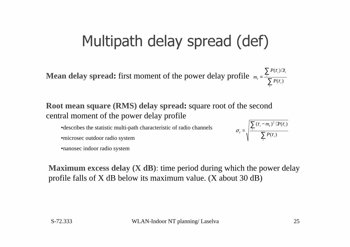
�$!��&����#�!�.��& ��#�)#�5*
( )
( )
i ii
ii
Pm
Pτ
τ τ
τ
⋅=
∑∑
Mean delay spread: first moment of the power delay profile
2( ) ( )
( )
i ii
ii
m P
P
τ
τ
τ τσ
τ
− ⋅=
∑∑
Root mean square (RMS) delay spread: square root of the secondcentral moment of the power delay profile
•describes the statistic multi-path characteristic of radio channels
•microsec outdoor radio system
•nanosec indoor radio system
Maximum excess delay (X dB): time period during which the power delayprofile falls of X dB below its maximum value. (X about 30 dB)
S-72.333 WLAN-Indoor NT planning/ Laselva 26
��#�(�����((�!Radio channels are time-variant because of the movement of environmental
objects or receivers.
– Fast fading or slow fading radio channel depending on how rapid the channelproperty changes over time.
• Based on relation between a signal’s parameter (symbol rate) and a channel’s parameters (RMSDelay Spread and Doppler Spread)
– Doppler Spread, BD: a measure of the spectral broadening to the signal• v is the velocity of mobile, c is the light speed constant• fc is the carrier frequency
D c
vB f
c= ⋅
– Coherent time TC: reciprocal of Doppler Spread
• characterises the time varying nature of the radio channel (if smaller than thesymbol period --> the channel is thought of as a fast fading channel)
Small scale fading describes:
• rapid fluctuations of the received signal power over a short period of time
• the travel distance due to the destructive addition of multi-path signals.
2 22
exp( / 2 ) (0 )( )
0 ( 0)Rayleigh
rr r
P rr
σσ
− → ≤ ≤ ∞= → <
2 2
02 2 2
( )exp( ) ( ) (0 )
( ) 20 ( 0)
Ricean
r r A ArI r
P r
rσ σ σ
+− → ≤ ≤ ∞= → <
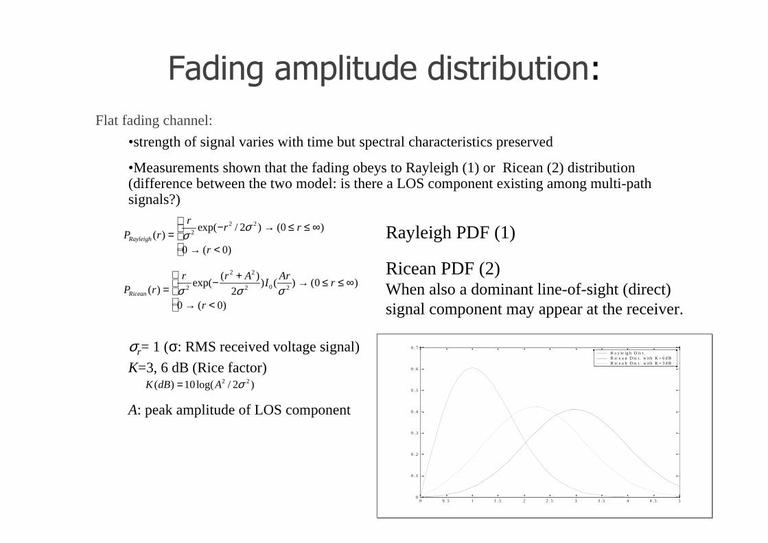
Rayleigh PDF (1)
Ricean PDF (2)When also a dominant line-of-sight (direct)signal component may appear at the receiver.
σr= 1 (σ: RMS received voltage signal)
K=3, 6 dB (Rice factor)
A: peak amplitude of LOS component
��#�(���"&!��$#��#��� ��$��'(1
2 2( ) 10log( / 2 )K dB A σ=
0 0 . 5 1 1 . 5 2 2 . 5 3 3 . 5 4 4 . 5 50
0 . 1
0 . 2
0 . 3
0 . 4
0 . 5
0 . 6
0 . 7R a y le ig h D is t .R ic e a n D is t . w ith K = 6 d BR ic e a b D is t . w ith K = 3 d B
Flat fading channel:
•strength of signal varies with time but spectral characteristics preserved
•Measurements shown that the fading obeys to Rayleigh (1) or Ricean (2) distribution(difference between the two model: is there a LOS component existing among multi-pathsignals?)
S-72.333 WLAN-Indoor NT planning/ Laselva 28
System parameters• Coherence bandwidth, Bc: measure of frequency range over which the
radio channel can be thought to be flat. (It is related to RMS delayspread of the channel)
– with the frequency correlation of 0.9
– with the frequency correlation of 0.5
– Rule of Thumb:�if a digital signal has a symbol duration which is morethan ten times the RMS delay spread στ
--> no equalizer is required for a bit error rates better than 10-3
cB 1/ 50 τσ≅
cB 1/ 5 τσ≅
• Frequency selective channel: different frequency components of a transmittedsignal experience different gains when across a radio channel.
• In time domain, such a channel will induce inter symbol interference (ISI) totransmitted signal, and the wave shape of signal is changed.--> equalization technique is required to cancel the effect of ISI

(#'' � �#�'�& '&�����'(�"'#�!Characteristics in indoor environments compared with outdoor radio systems and
applications :• distance between a TX and RX is shorter• power output of a TX is much lower• emc wave propagation complicated due to:
– the variation of building size, shape, structure, construction material
– TX and RX positions, and patterns of antenna radiation. Mutual visibility between the transmitter andreceiver antenna, the environments classification: line-of-sight (LOS), obstruct LOS (OLOS) and non-LOS(NLOS)
– Other factors: age of the building, neighbouring buildings, % of windows, people density and level of humanactivity
Four groups of models: - statistical models, which rely on extensive measurements (1, 2, 3)
- a site-specific model, which is based on the electromagnetic wave propagation theory or geometrical optics (4)
(1) narrow-band (for large scale propagation)
(2) empirical wide-band: >>study of the power delay profile
>> interested in RMS delay spread values,
>> the number of delay components for different types of environments
(3) time variation: study Doppler spread characteristic (e.g. the effects of human movement to the radio channel)
(4) deterministic: force methods to physically simulate indoor radio propagation

)�*�-"&� ���!�(� '�:��(#�"'#�!
• Focus on path loss of a radio wave in its propagation
• Based on the measurement results on different kind of building categories.Parameters can be adjusted to fit best for each type of environment.
(1) One-slop model: simplest path loss model
(2) Multi-Wall model: COST 231 Multi-Wall model given in (3),– defines path loss as the free-space loss plus excess loss introduced by
• walls and floors
• non-linear effect of multi-floor losses
2
1
1
f
f
l Kb
KFS c wi wi f fi
L L L K L K L +
− +
=
= + + +∑LFS free space loss; LC is constant loss (for measurement calibration, normally close to zero)
Kwi number of penetrated wall of type i; Kf is the number of penetrated floors
Lwi loss of wall type i; two types of walls used: a light wall, no weight, like plasterboard,particleboard, or a thin concrete wall. The second one is a heavy wall, a load-bearing wall or otherthick concrete wall; Lf is loss of the floor
(3)
expresses the total wall loss as a sum of individual wall loss
0 10 log( )L L n d= + ⋅

�$!��:+�!!�"'#�!
P aram eter(s) L igh t W a ll L o ss
(d B )
H eav y W all L o ss
(d B )
F lo o r L o ss (d B ) M ulti-flo o r N o n-
linea r fac to r b
V a lue 3 .4 6 .9 1 8 .3 0 .4 6
COST 231 Multi-Wall model reference parameters (wall or floor loss based on statisticalmeasurement results)
•Actual loss depends on - permittivity and conductance ( ε and σ) of the construction material
- incident angle θin
- polarization pattern of the signal in view of the reflection plane also affects the r.f. reflection coefficient.
• If radio wave incident from free space to the interface plane of two dielectrics materials with µ,the reflection coefficient:
2
// 2
sin cos
sin cos
i i
i i
ε θ ε θ
ε θ ε θ
− + −Γ =
+ −
2
2
sin cos
sin cos
i i
i i
θ ε θ
θ ε θ⊥
− −Γ =
+ −
ε: complex dielectric constant given by , ε0 is a constant (8.85 x 10⁻¹² F/m).
// denotes the E-field of the wave parallel to the incidence plane
⊥ denotes the E-field of the wave normal to the incidence plane The permittivity values ofcommonly used construction materials are available
If the reflector is a perfect conductor, then all the incidental energy will be reflected back andpractically no wave penetration can happen.
’0 r jε ε ε ε= −
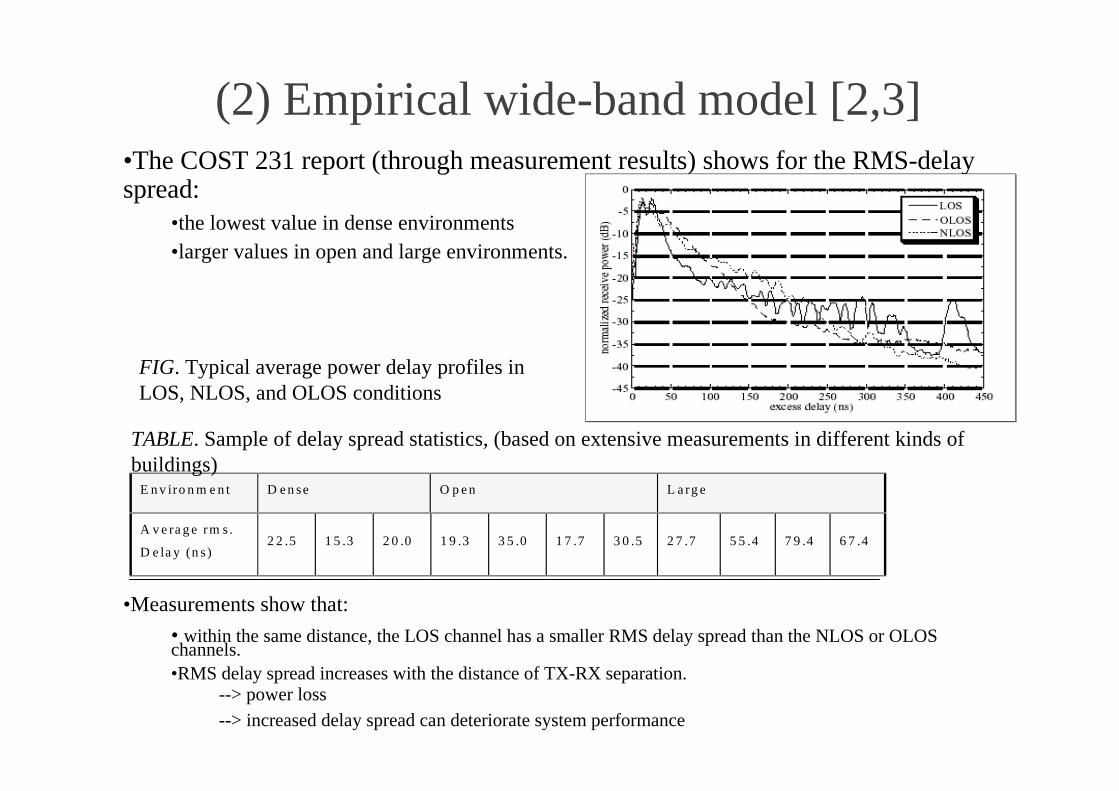
(2) Empirical wide-band model [2,3]•The COST 231 report (through measurement results) shows for the RMS-delayspread:
•the lowest value in dense environments•larger values in open and large environments.
•Measurements show that:
• within the same distance, the LOS channel has a smaller RMS delay spread than the NLOS or OLOSchannels.•RMS delay spread increases with the distance of TX-RX separation.
--> power loss--> increased delay spread can deteriorate system performance
E n v iro n m e n t D e n se O p e n L a rg e
A v e ra g e rm s .
D e la y (n s )2 2 .5 1 5 .3 2 0 .0 1 9 .3 3 5 .0 1 7 .7 3 0 .5 2 7 .7 5 5 .4 7 9 .4 6 7 .4
FIG. Typical average power delay profiles inLOS, NLOS, and OLOS conditions
TABLE. Sample of delay spread statistics, (based on extensive measurements in different kinds ofbuildings)
S-72.333 WLAN-Indoor NT planning/ Laselva 33
(3) Time variation model
• Time variations of indoor radio channels introduced by severalmechanisms:
•movement of mobile stations;
•change of orientation of antennas due to their non-isotropic pattern;
•movement of scattering objects near mobile stations.
-->the fast fluctuation of signal strength over a small distance is knownas the vector addition of multi-path signals.
•In indoor environment, human beings are the most important source ofscattering or shadowing:
•Measurements show that a body across the radio link close to a receiver can introduce a fading of upto 20 dB. Random movement of people near a fixed receiver cause signal fading similar to the case inwhich the receiver is moving in small scale .
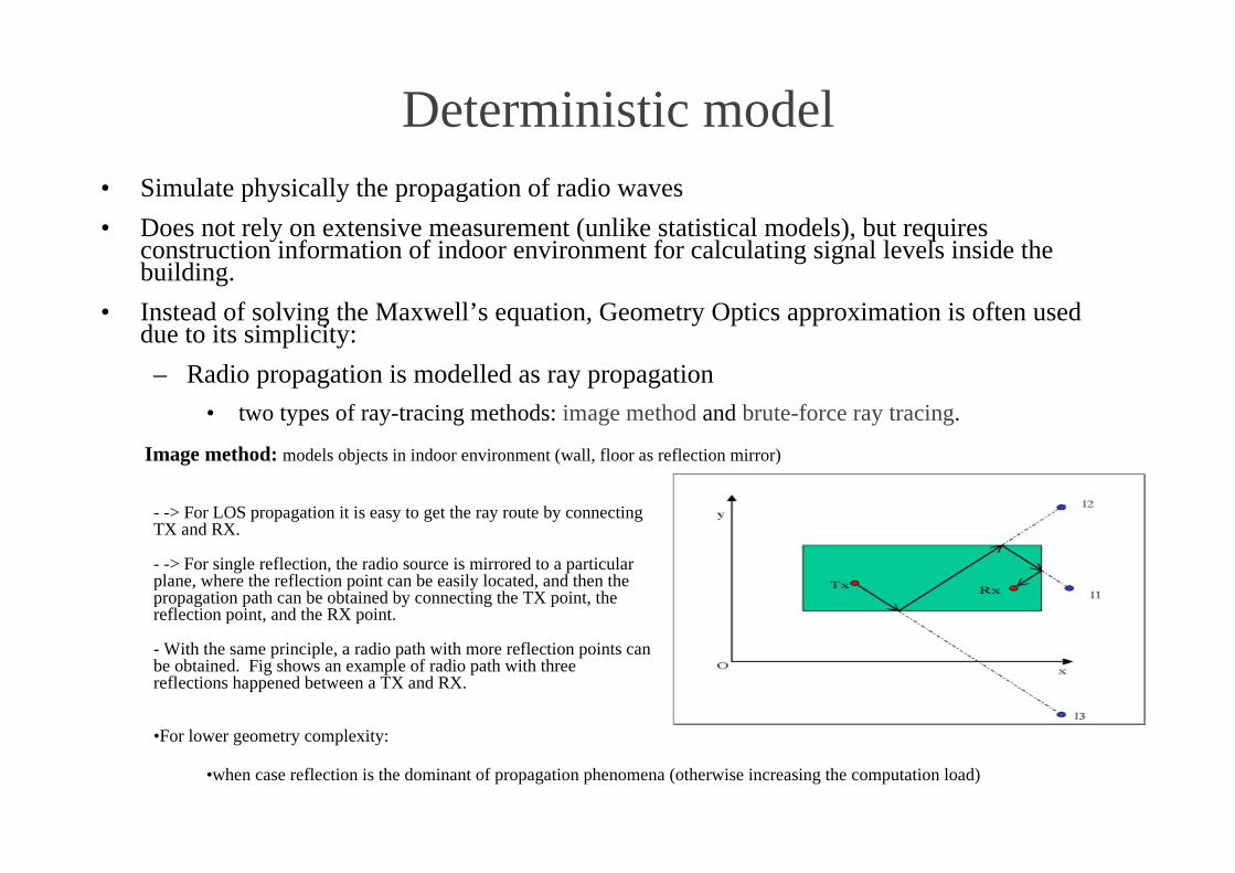
Deterministic model• Simulate physically the propagation of radio waves
• Does not rely on extensive measurement (unlike statistical models), but requiresconstruction information of indoor environment for calculating signal levels inside thebuilding.
• Instead of solving the Maxwell’s equation, Geometry Optics approximation is often useddue to its simplicity:
– Radio propagation is modelled as ray propagation
• two types of ray-tracing methods: image method and brute-force ray tracing.
- -> For LOS propagation it is easy to get the ray route by connectingTX and RX.
- -> For single reflection, the radio source is mirrored to a particularplane, where the reflection point can be easily located, and then thepropagation path can be obtained by connecting the TX point, thereflection point, and the RX point.
- With the same principle, a radio path with more reflection points canbe obtained. Fig shows an example of radio path with threereflections happened between a TX and RX.
Image method: models objects in indoor environment (wall, floor as reflection mirror)
•For lower geometry complexity:
•when case reflection is the dominant of propagation phenomena (otherwise increasing the computation load)

S-72.333 WLAN-Indoor NT planning/ Laselva 35
Diversity techniquesPowerful technique: provides improvement on radio link performance
with a relative low cost:
– Avoids using channel estimation (like in equalization), which requirestraining sequence or overhead in a data frame
– Explores the random nature of radio channels and utilises informationprovided by different paths.
Many different diversity methods available:
•space diversity
•frequency diversity
•polarization diversity
•angular diversity
•time diversity.
S-72.333 WLAN-Indoor NT planning/ Laselva 36
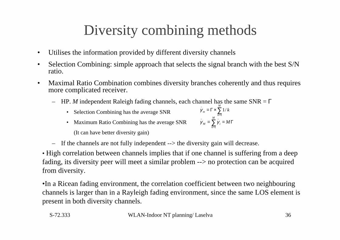
Diversity combining methods• Utilises the information provided by different diversity channels
• Selection Combining: simple approach that selects the signal branch with the best S/Nratio.
• Maximal Ratio Combination combines diversity branches coherently and thus requiresmore complicated receiver.
– HP. M independent Raleigh fading channels, each channel has the same SNR = Γ• Selection Combining has the average SNR
• Maximum Ratio Combining has the average SNR
(It can have better diversity gain)
– If the channels are not fully independent --> the diversity gain will decrease.
_
1
1/M
mk
kγ=
= Γ×∑_ _
1
M
M ik
Mγ γ=
= = Γ∑
• High correlation between channels implies that if one channel is suffering from a deepfading, its diversity peer will meet a similar problem --> no protection can be acquiredfrom diversity.
•In a Ricean fading environment, the correlation coefficient between two neighbouringchannels is larger than in a Rayleigh fading environment, since the same LOS element ispresent in both diversity channels.

S-72.333 WLAN-Indoor NT planning/ Laselva 37
Space diversity and polarity diversity
• Space diversity (7-8 dB gain) is implemented by spatial separation of receiverantennas.
– In indoor environments, a wide angular spread is expected which allows a small antennaseparation.
– Conventionally assumed that under Omni-directional wave incidence the minimal distancebetween two diversity antenna is about λ/2 or 0.4λ [4] Measurements show that in NLOSenvironments, the correlation factor drops to a level of 0.4~0.6 at a fraction of awavelength antenna separation
• Polarity diversity (9-10 dB gain) can be applied due to depolarizationphenomena. The reflection, scattering, absorption, or human body may alterthe polarity of radio signals. The amount of depolarization determines thegain from polarity diversity.
– Measurements show the cross-polarization effect in various propagation conditions.
– Polarization diversity antennas can be placed closely together or even coincidentallywithout any significant mutual interference

S-72.333 WLAN-Indoor NT planning/ Laselva 38
WLAN antennas• Antennas (Omni-directional and directional) with
– different gain (dBi, the ratio of the maximum radiation intensity to the averageradiation intensity)
– radiation pattern (graphical representation of radiation of the antenna measured in twoorthogonal planes: vertical and horizontal in a polar structure)
– polarization used in different environments for providing a better coverage andcapacity for a radio network.
• Omni-directional antenna: provides a 360 degree radiation pattern onhorizontal plane. (e.g. λ/2 dipole antenna, which provides a 2.14 dBi gain)
• Directional antennas designed to transmit more energy in one direction(e.g. Yagi antenna, patch antenna, or parabolic dish antenna).
-->more narrow the 3dB bandwidth, the more gain the antenna provides.

PCMCIA integrated antenna• Approaches to arrange antenna in a small space
• Diversity or polarity diversity implemented:
– Polarization diversity solves the problem that dimensions of mobile terminal limitthe spatial separation of diversity antennas in designing of a PCMCIA integrationantenna.
• A standard type PCMCIA WLAN card includes– a baseband part– a radio transceiver unit part– an antenna part on the extended body of the card.
Different approaches have been made to arrange antenna in a small space (3 cm x 5cmx 0.5 cm). Fig shows the space diversity antenna radiation patterns plot:
Antenna A (dBi)
-40.00-30.00-20.00-10.00
0.00
01530
45607590105
120135
150165180
195210225
240255270285300
315330345
Antenna B (dBi)
-40.00-30.00-20.00-10.00
0.00
01530
45607590105
120135
150165180
195210225
240255270285300
315330345
(a) (b)
Gain of the PCMCIA antenna is poor(average lessthan 0 dBi) because:
- Omni-directional since the radio signal cancome from any direction.
- Gain is limited by the size of PCMCIA card.
OSS: radiation pattern is not real omni-directional.In some direction, the gain can be less than –30dBi, which means very strong attenuation. Twodiversity branches are placed in certain directionsin which two deep fading directions are apart fromeach other.

S-72.333 WLAN-Indoor NT planning/ Laselva 40
NETWORK PLANNING FOR IEEE 802.11WLAN
• To maximise network performance with defined budget and equipment
– Network performance includes dependent aspects: throughput, coverage,roaming, interference, security, etc.
-->the planning process helps controlling the project in a systematic manner, in which allrelevant information is collected and analysed beforehand in order to avoid costlycorrection.
• Planning process includes:
– Requirement management
– Investigating existing network
– Coverage planning
– Capacity planning
– and frequency planning

�/$� �"�(��"�(���"�(�• Consists of
– requirement collection– requirement analysis (a critical phase because the system must fulfil customer’s needs or expectations)
• Business requirement: e.g. budget, time frame, and human resource
•Management interested in the impact of new technology on productivity of their workforce. The model ofa Return of Investment (ROI) usually can stimulate top management to make a decision.
• Functional requirement: describes what new functionality the wireless network plans toprovide.
•E.g. In campus environment, the wireless network may provide general Internet accesses for student andfaculty.
•E.g. In corporation environment, it may provide a secure mobile connection to the company’s Intranet.
• Performance requirement: quality of service requested by certain group of users. (e.g.networkcoverage, data throughput, equipment compatibility and others)
• Management requirement e.g. network management interface, interface to backbone, IP addressallocation mechanism, authentication & data security features, and technical support services (to minimized)
- Requirements collected from different user groups put together, discussed, balance or compromise is necessarybetween different requirements.
- Validation and verification processes will be arranged.
- Important to document requirements in a clear and easily understood format.
(3��������(���2����(���(3� '("�(��• Good understanding of existing wired network structure is helpful in designing the WLAN network
(extension)– Useful information: the positions of Ethernet outlets or electricity sockets.
– To minimise extra cabling work and not disturb existing network services.
– Besides the physical layer information, the structure of the upper layer of the existing network should also be investigated.For example, the IP address allocation principal, Virtual LAN structure, network services, security policy, etc. should beinvestigated.
• Baseline of network planning (investigation started from reviewing the blueprint of the areas, e.g. inAutoCAD format, a site visit may be necessary in some cases to check out of date doc.):
– constructional structure of planning areas
– functionality of each area
• Interference survey Interference avoidance is very critical for designing a WLAN as it operates in anuncontrolled ISM band. A network planning without interference analysis may cause serious consequences innetwork performance
With a spectrum analyzer or other channel scan tools, the network planner tries to locate
– source of interference source to the planned network, their used frequencies and their power level.
– Interference may come from other 802.11 WLAN systems, Bluetooth terminals, Microwave ovens, or other radio systems.
• Output of this phase of work is a report, containing the following information:1. Customer information: work group name, address, contact person, etc.2. Site information: information on building structures, construction materials, and possible restrictionson radio equipment installation.3. Interference survey results: interference sources and their severity assessment.4. Networking information, Ethernet interface specification, locations of Ethernet Switches or accessoutlets, IP allocation mechanisms or VLAN configurations.

S-72.333 WLAN-Indoor NT planning/ Laselva 43
�'3� ����&!�((�(�
• Core of the WLAN planning process:
– based on the information obtained from requirement analysis and environmentinvestigation, network planning is focused on finding the places of installing accesspoint, with suitable antenna patterns
– Link Budget
– Locate AP positions
– Computer-aided planning
– Field measurements and site survey
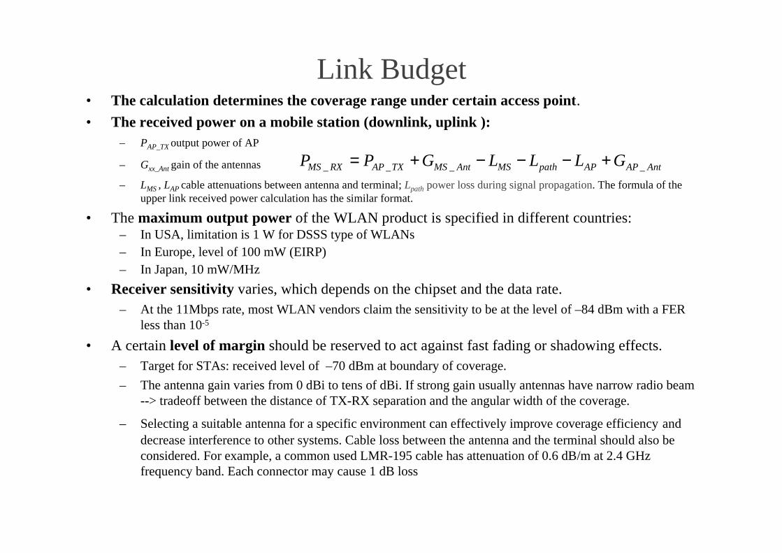
Link Budget• The calculation determines the coverage range under certain access point.
• The received power on a mobile station (downlink, uplink ):– PAP_TX output power of AP
– Gxx_Ant gain of the antennas
– LMS , LAP cable attenuations between antenna and terminal; Lpath power loss during signal propagation. The formula of theupper link received power calculation has the similar format.
• The maximum output power of the WLAN product is specified in different countries:– In USA, limitation is 1 W for DSSS type of WLANs– In Europe, level of 100 mW (EIRP)– In Japan, 10 mW/MHz
• Receiver sensitivity varies, which depends on the chipset and the data rate.– At the 11Mbps rate, most WLAN vendors claim the sensitivity to be at the level of –84 dBm with a FER
less than 10-5
• A certain level of margin should be reserved to act against fast fading or shadowing effects.– Target for STAs: received level of –70 dBm at boundary of coverage.
– The antenna gain varies from 0 dBi to tens of dBi. If strong gain usually antennas have narrow radio beam--> tradeoff between the distance of TX-RX separation and the angular width of the coverage.
– Selecting a suitable antenna for a specific environment can effectively improve coverage efficiency anddecrease interference to other systems. Cable loss between the antenna and the terminal should also beconsidered. For example, a common used LMR-195 cable has attenuation of 0.6 dB/m at 2.4 GHzfrequency band. Each connector may cause 1 dB loss
_ _ _ _MS RX AP TX MS Ant MS path AP AP AntP P G L L L G= + − − − +

S-72.333 WLAN-Indoor NT planning/ Laselva 45
Locate AP positions• This is a primary planning step based on blueprint of building (fixed installation of
an AP or antenna is preferred)
Other important aspects:
– furniture (not shown)
– any large obstacle existing in the area under planning
• e.g. metal bookshelves or cabinets can cause very strong signal attenuation. The existing networkinfrastructure affects much of the implementation of the WLAN. For a quick rollout, extra cablingwork is always burdensome and should be minimized. Sometimes it is expensive to install powersockets in your selected place. The available resources are always good to use first. By this principlethere may have to be certain compromise between best performance and easier installation. Currentlymany Ethernet switches in the market support transmitting DC power over CAT-5 Ethernet cables.This solution can reduce some cabling work on power supply.
– Aesthetic requirements or health considerations: e.g.uncomfortable seeing antennas outthrough the ceilings.
• Currently selecting AP locations in most WLAN planning practice is a “best-guessing” approach:
– Selection is based on the information acquired from user requirements and field investigation.– Selection is dependent upon much on people’s experience in the field. If more than one
candidate sites are selected, a computer aided planning tool is used to make comparison andoptimization
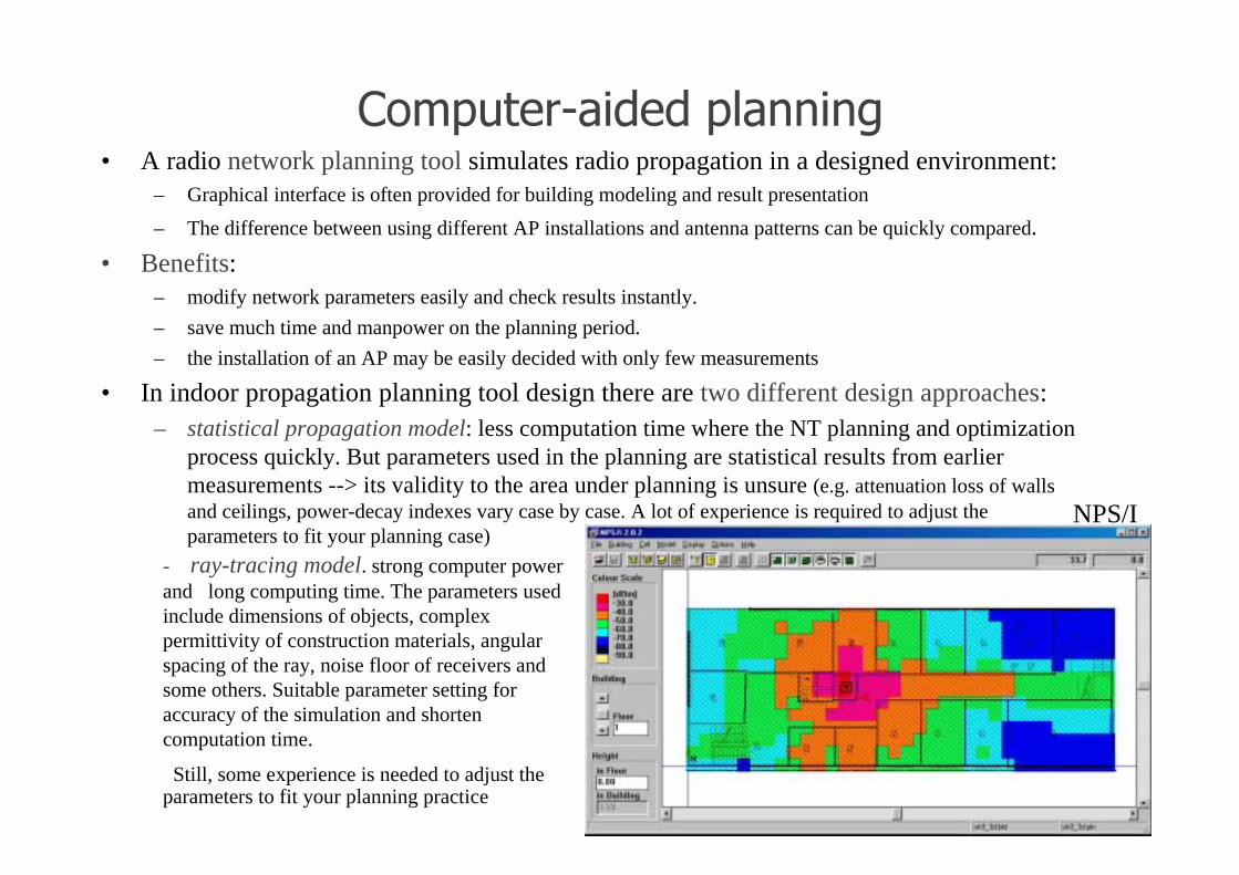
�'"&$�� :��#�#�&!�((�(�• A radio network planning tool simulates radio propagation in a designed environment:
– Graphical interface is often provided for building modeling and result presentation
– The difference between using different AP installations and antenna patterns can be quickly compared.
• Benefits:– modify network parameters easily and check results instantly.
– save much time and manpower on the planning period.
– the installation of an AP may be easily decided with only few measurements
• In indoor propagation planning tool design there are two different design approaches:– statistical propagation model: less computation time where the NT planning and optimization
process quickly. But parameters used in the planning are statistical results from earliermeasurements --> its validity to the area under planning is unsure (e.g. attenuation loss of wallsand ceilings, power-decay indexes vary case by case. A lot of experience is required to adjust theparameters to fit your planning case)
- ray-tracing model. strong computer powerand long computing time. The parameters usedinclude dimensions of objects, complexpermittivity of construction materials, angularspacing of the ray, noise floor of receivers andsome others. Suitable parameter setting foraccuracy of the simulation and shortencomputation time.
Still, some experience is needed to adjust theparameters to fit your planning practice
NPS/I

S-72.333 WLAN-Indoor NT planning/ Laselva 47
���!#�"���$ �"�(����(#�������$ 3�.
• In computer-aided planning (environment is much simplified) natural a certain level oferror or offset existing between the measurement and simulation. Knowledge of errorused to improve the accuracy of planning in similar environments later.
• Measurements used to check:– the actual coverage of the network
– whether the coverage plan is realized in the real situation. The basic tool used in WLAN measurement is awireless PC card and its utility software, e.g. client manager.
– Types of tools can display signal strength, SNR, packet error ratio, etc. Some tools that support periodicscanning and auto-discovery of stations on all channels can be used to find interfering WLAN systems.
• Advanced site survey tools available: for trouble-shooting of WLAN networks. Tools asnetwork analyzers, which can trace both physical and data link layer data.
– On the PHY layer, they can monitor radio performance and check the source of interference
– On the data link layer, they can analyse protocol layer error, and maintain network securityand service performance.
– E.g. Site survey tool is ProCycle™ which is developed by SoftBit, a Finnish company• An integrated tool supporting signal/interference measurement, data post-processing, coverage
visualization, throughput testing, report generation and other functionalities.

��&����.�&!�((�(�• Theoretical data transport rate of the IEEE 802.11b is 11 Mbps. However:
– due to the CSMA/CA mechanism used in the MAC layer– management frames used both in physical and data link layer,--> the effective data throughput of the WLAN is only 6.5 Mbps [5]– When the data rate drops to 5.5 Mbps or 2 Mbps due to weak signal level or lower SNR, the
actual date throughput drops also.
Number of simultaneous usersEnvironment Traffic content Traffic Load
11Mbps 5.5Mbps 2Mbps
Corporation
Wireless LAN
Web, Email, File
transfer
150 kbits/user 40 20 9
Branch Office
Network
All application via
WLAN
300 kbits/user 20 10 4
Public Access Web, Email, VPN
tunneling
100 kbits/user 60 30 12
TABLE Typical traffic load in different environ, # simultaneous users severed
The supported usernumber claimed bydifferent vendors variesfrom 20 to 200 -->selection product whichmeets capacityrequirement.
• # of supported users in one cell is also limited:
- by the processing power of AP hardware: some features consume much of the resources of the AP:
• AP processes functions like authentication, association, encryption and roaming, etc. Some high-endAPs integrate proprietary functions such as a VPN server, or Access Control List functionality, etc
S-72.333 WLAN-Indoor NT planning/ Laselva 49
� �/$�(�.�&!�((�(�
• It focuses on:
– choosing correct frequency channels for APs and client terminals.
• Since the WLAN operates on ISM band, RF interference issues continuouslyexist as a risk to the operation performance of your WLAN network.
• The IEEE 802.11 uses the CSMA/CA protocol as a medium access controlmethod. If an interference signal is present at certain channel, that channel willbe considered busy and all other stations will have to wait until interferencedisappears. Several interference sources have serious effects to IEEE 802.11WLANs:
– Interference from other WLAN systems
– Interference from microwave ovens
– Interference from Bluetooth devices

Interference from other WLAN systems• While the number of cells and positions of APs are decided in earlier planning phases, a
radio channel or a frequency point will be allocated to each AP.--> Interference from other WLAN elements, either from other networks or its own network, are all relevant to frequency selection.
– The IEEE 802.11 standard defines 14 overlapped radio channels.
-->Two channels with a 5-channel separation do not interfere each other. For example, Channel 1, 6, and 11 can work in thesame area without interference. Clearly the frequency resource for 802.11 is very limited.
• In coverage planning, a certain level of fading margin was reserved for receivers at cellborder:
– When two cells have the same size overlap-->signal levels from both APs have similar strengths The data throughput in theoverlapping area will deteriorate if the frequency space of the two APs is less than 25 MHz. (It is assumed that signal levelsreceived from the both APs are strong enough to have the full capacity and therefore the interference is the only reason todeteriorate the network performance)
•The effect of interference can be minimized through the use of some counter-measures:adjusting channel spacing, decreasing AP’s output power, using directive antennas, usingsmaller packet fragment sizes, using high speed PC cards, using load sharing mechanisms, etc.
• Ex. three 120-degree sector antennas in a flat coverage planning
• Several advantages in using sectored configuration:
•More capacity, since there are three frequencies (channels) for one cell
•Stronger signal level, since there is a higher gain of directive antenna
•Better frequency reuse, since the sector antenna can be down-tilted toground and less power will be radiated to the horizontal plane
•Good front to back ratio (F/B), which can reduce the interference from/tothe stations behind the sector antenna
S-72.333 WLAN-Indoor NT planning/ Laselva 51
Interference from microwave oven• Microwave ovens radiate radio signals at the ISM band.
– Central frequency varies with different magnetron components. (it varies from 2450 MHzto 2458 MHz)
– Some work reported that radiation emission of Microwave ovens exists also at 1.9 GHzband and second harmonics band (4.9 GHz)
– Ovens have the strongest emission at the 2.45 GHz band• it leads a strong interference to the 802.11 WLAN system operating on the radio band
from 2.412 GHz to 2.462 GHz.
• The signal radiated has bursty impulsive characteristics in time domain andthe bursts are periodic (burst period is measured = 10 µs, active part is 5 µs)
– Measured from 3 meters away, the active pulse has a power level of 18 dBm, which isstronger than the power of most IEEE 802.11 products
– As one symbol period in 802.11 DSSS is one µs, multiple symbols are corrupted in onenoise burst. Measurement result shows, in a LOS situation, that a minimum of 21 metersdistance is required for eliminating the effect of interference.
• A solution for microwave oven interference is to keep the oven away fromthe WLAN’s working area or to install an RF absorber to the microwaveoven.
(�� 5� �(���5 '"�8!$��''��• Bluetooth:
– stack of protocols– realizes wireless data communication between mobile terminals– standard supported by the Bluetooth Special Interest Group (SIG, Ericsson, IBM, Intel, Nokia, and Toshiba
in 1998)
• Work in ad-hoc mode and is intended to be a cable replacement technology:– low data rate (max capacity is 740Kbps per piconet)– low power output– small coverage area
• Operate at the same ISM band from 2.4 GHz to 2.485 GHz• Use the FHSS with 79 channels with the hop rate of 1600 hops per second.
– Each channel is 1 MHz in width.– The collision of WLAN and Bluetooth packages is unavoidable if two systems are operating in the
same area.• Assuming Bluetooth has the packet period of 635 µs and 11 Mbps WLAN works with the 1500 Byte MAC
layer payload, the probability of a WLAN frame collision with Bluetooth packets is about 48% to 62% [6]: thisheavy collision ratio will seriously deteriorate the performance of WLAN.
• Other factors, (relative level of two signals, the activity of Bluetooth terminals, the packet size of WLANsystem, etc) effects also the frame error rate: many researches give throughout analysis on WLANperformance under Bluetooth interference [7].
• The coexistence of two technologies will certainly continue for a long time– many solutions have been proposed to solve the interference problem. As a practical solution,
limiting the usage of Bluetooth terminals or limiting its power level in the WLAN area can eliminatethe interference
– The IEEE 802.15 has a task group working on the issue. So far there is no official standard published.
S-72.333 WLAN-Indoor NT planning/ Laselva 53
���$ ��.
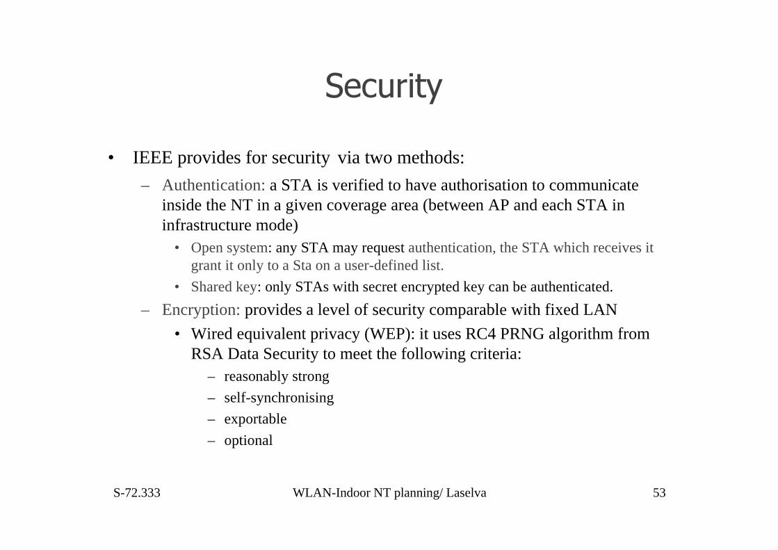
• IEEE provides for security via two methods:
– Authentication: a STA is verified to have authorisation to communicateinside the NT in a given coverage area (between AP and each STA ininfrastructure mode)
• Open system: any STA may request authentication, the STA which receives itgrant it only to a Sta on a user-defined list.
• Shared key: only STAs with secret encrypted key can be authenticated.
– Encryption: provides a level of security comparable with fixed LAN
• Wired equivalent privacy (WEP): it uses RC4 PRNG algorithm fromRSA Data Security to meet the following criteria:
– reasonably strong
– self-synchronising
– exportable
– optional
S-72.333 WLAN-Indoor NT planning/ Laselva 54
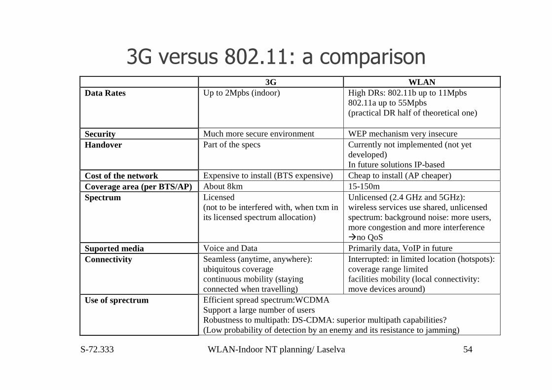
;<�3� �$���� ���1����'"&� ��'( 3G WLAN Data Rates Up to 2Mpbs (indoor) High DRs: 802.11b up to 11Mpbs
802.11a up to 55Mpbs (practical DR half of theoretical one)
Security Much more secure environment WEP mechanism very insecure Handover Part of the specs Currently not implemented (not yet
developed) In future solutions IP-based
Cost of the network Expensive to install (BTS expensive) Cheap to install (AP cheaper) Coverage area (per BTS/AP) About 8km 15-150m Spectrum Licensed
(not to be interfered with, when txm in its licensed spectrum allocation)
Unlicensed (2.4 GHz and 5GHz): wireless services use shared, unlicensed spectrum: background noise: more users, more congestion and more interference �no QoS
Suported media Voice and Data Primarily data, VoIP in future Connectivity Seamless (anytime, anywhere):
ubiquitous coverage continuous mobility (staying connected when travelling)
Interrupted: in limited location (hotspots): coverage range limited facilities mobility (local connectivity: move devices around)
Use of sprectrum Efficient spread spectrum:WCDMA Support a large number of users Robustness to multipath: DS-CDMA: superior multipath capabilities? (Low probability of detection by an enemy and its resistance to jamming)

S-72.333 WLAN-Indoor NT planning/ Laselva 55
References[1] Jean Armstrong OFDM – Orthogonal FrequencyDivision Multiplexing-La Trobe University[2] Nobles, P. Halsall, F- Delay spread and received power measurements within a building at 2 GHz, 5 GHz
and 17 GHz. Antennas and Propagation, Tenth International Conference, vol. 2, pp. 319 –324, 1997[3] Babich, F. Lombardi, G. Valentinuzzi, E.- Indoor propagation characteristics in DECT band.Vehicular
Technology Conference, Mobile Technology for the Human Race, IEEE 46th , vol. 1, pp. 574 –578,1996
[4] Liebendorfer, M.; Dersch, U- Wireless LAN diversity antenna system for PCMCIA card integration.Vehicular Technology Conference, IEEE 47th, vol. 3, pp. 2022 -2026, 1997
[5] Nokia Mobile Phone -WLAN site survey training document. Nokia Internal Document, 2000[6] Mim, R. 2001: Collision Course, how bluetooth interference impacts wireless LANs. Proxim Inc. White
Paper[7] Shellhammer, S. 2000: Packet Error Rate of an IEEE 802.11 WLAN in the Presence of Bluetooth. IEEE
802.15 Document, 00/133r0[8] Yulin Qi, Indoor networking planning for IEEE 802.11 based WLANs, Espoo, Master’s thesis, 2002[9] Indoor Network planning for IEEE 802.11 based WLANs 85 IEEE 802.11, 1999: IEEE standard for
Information Technology -Telecommunications and information exchange between systems – LANand.MANs -Specific requirements- Wireless LAN (MAC) and Physical Layer (PHY) Specifications,1999 edition
[10] Supplement to 802.11, 1999: Wireless LAN MAC and PHY specifications: Higher speed Physical Layer(PHY) extension in the 5GHz band
[11] Supplement to 802.11, 1999: Wireless LAN MAC and PHY specifications: Higher speed Physical Layer(PHY) extension in the 2.4GHz band

HOMEWORKl List briefly the main differences between 802.11a and 802.11.b (in terms of bandwidth, capacity,
coverage).
2 Explain why 802.11a that operates in 5GHz bands has a lower coverage area compared to802.11b. (Consider link budget and path loss)
3 Explain briefly why CSMA/CD (Ethernet) is not possible in WLAN (consider also theattenuation)
4 The MAC access mechanism is improved by using the Request-to-Send (RTS)/Clear-to-Send(CTS) and NAV packets for a better sharing of the medium (see the Timing Diagram below).
Explain briefly the relationship between:
a The size of data packet issued to a RTS packet.
b Number of times the TX STA resends a RTS if it does not receive a CTS packet from thepreviously sent RTS packet.
FIG. Timing Diagram
Note that Short Inter-frame Space (SIFS)
and DCF-IFS(DIFS) are mandatory
periods of idle time used.
E.g.Transmission possible when the channel is stable (idle) for at least an DIFS
DIFS Data
SIFS
CTS
RTS
SIFS
SIFS
ACK
Source
Destination
DIFS Data
SIFS
CTS
RTS
SIFS
SIFS
ACK
Source
Destination
DIFS
NAV(RTS)
Defer Access
CW
NAV(CTS)
NAC(data)
Other
DIFS
NAV(RTS)
Defer Access
CW
NAV(CTS)
NAC(data)
Other
RTS
CTS
DATA
ACK
RTS
CTS
DATA
ACK

S-72.333 WLAN-Indoor NT planning/ Laselva 57
���-=�>1��������������� ����• Access control: The prevention of unauthorized usage of resources.
• Access point (AP): Any entity that has station functionality and provides access to the distribution services, viathe wireless medium (WM) for associated stations.
• Ad hoc network: A network composed solely of stations within mutual communication range of each other viathe wireless medium (WM). An ad hoc network is typically created in a spontaneous manner. The principaldistinguishing characteristic of an ad hoc network is its limited temporal and spatial extent. These limitationsallow the act of creating and dissolving the ad hoc network to be sufficiently straightforward and convenient soas to be achievable by non-technical users of the network facilities i.e., no specialized “technical skills” arerequired and little or no investment of time or additional resources is
• required beyond the stations that are to participate in the ad hoc network. The term ad hoc is often used as slangto refer to an independent basic service set (IBSS).
• Association: The service used to establish access point/station (AP/STA) mapping and enable STA invocationof the distribution system services (DSSs).
• Authentication: The service used to establish the identity of one station as a member of the set of stationsauthorized to associate with another station.
• Basic service area (BSA): The conceptual area within which members of a basic service set (BSS) maycommunicate.
• Basic service set (BSS): A set of stations controlled by a single coordination function.
• Basic service set (BSS) basic rate set: The set of data transfer rates that all the stations in a BSS will becapable of using to receive frames from the wireless medium (WM). The BSS basic rate set data rates are presetfor all stations in the BSS.
• Broadcast address: A unique multicast address that specifies all stations.

S-72.333 WLAN-Indoor NT planning/ Laselva 58
���-=�>1��������������� ����• Channel: An instance of medium use for the purpose of passing protocol data units (PDUs) that may be used
simultaneously, in the same volume of space, with other instances of medium use (on other channels) by otherinstances of the same physical layer (PHY), with an acceptably low frame error ratio due to mutual interference.Some PHYs provide only one channel, whereas others provide multiple channels. Coordination function: Thelogical function that determines when a station operating within a basic service set (BSS) is permitted to transmitand may be able to receive protocol data units (PDUs) via the wire-less medium (WM). The coordination functionwithin a BSS may have one point coordination
• function (PCF) and will have one distributed coordination function (DCF).• Coordination function pollable: A station able to (1) respond to a coordination function poll with a data frame, if
such a frame is queued and able to be generated, and (2) interpret acknowledgments in frames sent to or from thepoint coordinator.
• De-authentication: The service that voids an existing authentication relationship.• Directed address: A frame that is addressed to a single recipient, not a broadcast or multicast frame.• Disassociation: The service that removes an existing association.• Distributed coordination function (DCF): A class of coordination function where the same coordination function
logic is active in every station in the basic service set (BSS) whenever the network is in operation.• Independent Basic Service Set (IBSS): A BSS that forms a self-contained network, and in which no access to a
Controlling Access Point (AP) is available.• Infrastructure BSS: The infrastructure includes the access point (AP), and stations.• Medium access control (MAC) management protocol data unit (MMPDU): The unit of data exchanged
between two peer MAC entities to implement the MAC management protocol.• Medium access control (MAC) protocol data unit (MPDU): The unit of data exchanged between two peer MAC
entities using the services of the physical layer (PHY).• Medium access control (MAC) service data unit (MSDU): Information that is delivered as units between MAC
service access points (SAPs).• Mobile station: A type of station that uses network communications while in motion.

S-72.333 WLAN-Indoor NT planning/ Laselva 59
���-=�>1��������������� ����• Multicast: A medium access control (MAC) address that has the group bit set. A multicast MAC service
data unit (MSDU) is one with a multicast destination address. A multicast MAC protocol data unit(MPDU) or control frame is one with a multicast receiver address.
• Network allocation vector (NAV): An indicator, maintained by each station, of time periods whentransmission onto the wireless medium (WM) will not be initiated by the station whether or not thestation’s clear channel assessment (CCA) function senses that the WM is busy.
• Point coordination function (PCF): A class of possible coordination functions in which thecoordination function logic is active in only one station in a basic service set (BSS) at any given time thatthe network is in operation.
• Portable station: A type of station that may be moved from location to location, but that only usesnetwork communications while at a fixed location.
• Re-association: The service that enables an established association [between access point (AP) andstation (STA)] to be transferred from one AP to another (or the same) AP.
• Station (STA): Any device that contains an IEEE 802.11 conformant medium access control (MAC) andphysical layer (PHY) interface to the wireless medium (WM).
• Station basic rate: A data transfer rate belonging to the extended service set (ESS) basic rate set that isused by a station for specific transmissions. The station basic rate may change dynamically as frequentlyas each medium access control (MAC) protocol data unit (MPDU) transmission attempt, based on localconsiderations at that station.
• Station service (SS): The set of services that support transport of medium access control (MAC) servicedata units (MSDUs) between stations within a basic service set (BSS).
• Time unit (TU): A measurement of time equal to 1024 µs.• Unicast frame: A frame that is addressed to a single recipient, not a broadcast or multicast frame.• Wireless medium (WM): The medium used to implement the transfer of protocol data units (PDUs)
between peer physical layer (PHY) entities of a wireless local area network (LAN).

S-72.333 WLAN-Indoor NT planning/ Laselva 60
���-=�>1��0�=�����?-?-+
Upcoming Standards: MAC:802.11 i - Enhanced Security Mechanism802.11 e - MAC enhancement – QoS802.11 f - Inter Access Point Protocol
PHY:802.11g – Extension to 802.11b

���-=�>1��2�"&!���'5���(#��!!'����'(


![WLAN Fingerprinting based Indoor Positioning in the ... · [17] which normally require additional specialized hardware, the others use the radio signal strength information, i.e.,](https://img.pdfslide.net/doc/110x75/60e5a93446073b3ede7ce359/wlan-fingerprinting-based-indoor-positioning-in-the-17-which-normally-require.jpg)