Embed Size (px)
Citation preview
S-72.3240 Wireless Personal, Local, Metropolitan, and Wide Area Networks 1
WLAN, part 1
Contents
IEEE 802.11 WLAN architecture• Basic routing example• IAPP and mobility management• Basic frame structure • MAC header structure• Usage of MAC address fields
Management frames
Some IEEE 802.11 standard amendments
S-72.3240 Wireless Personal, Local, Metropolitan, and Wide Area Networks 2
WLAN, part 1
IEEE 802.11 WLAN architecture
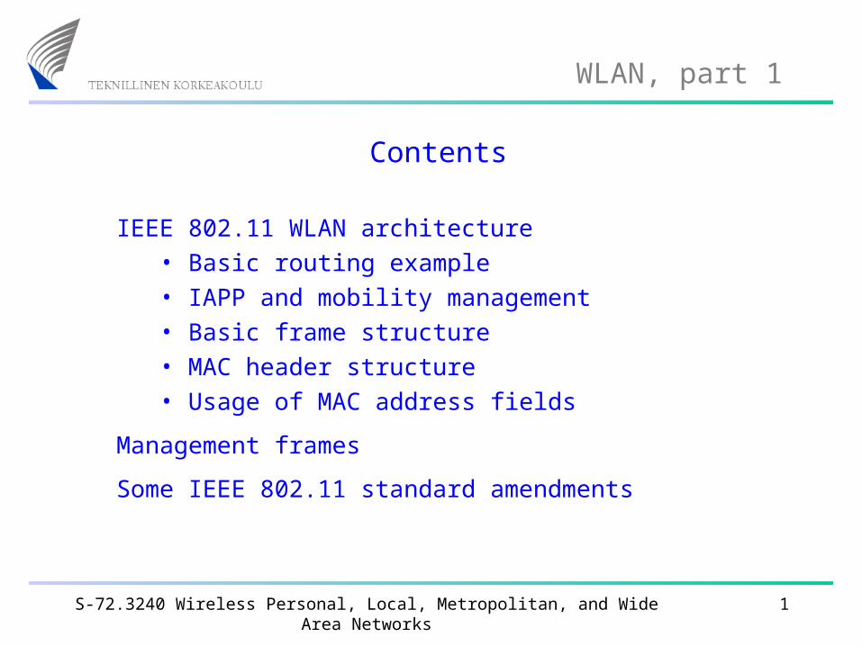
802.11 defines two BSS (Basic Service Set) options:
Infrastructure BSS Independent BSS(Ad-Hoc network)
APw
ired L
AN
S-72.3240 Wireless Personal, Local, Metropolitan, and Wide Area Networks 3
WLAN, part 1
Infrastructure BSS
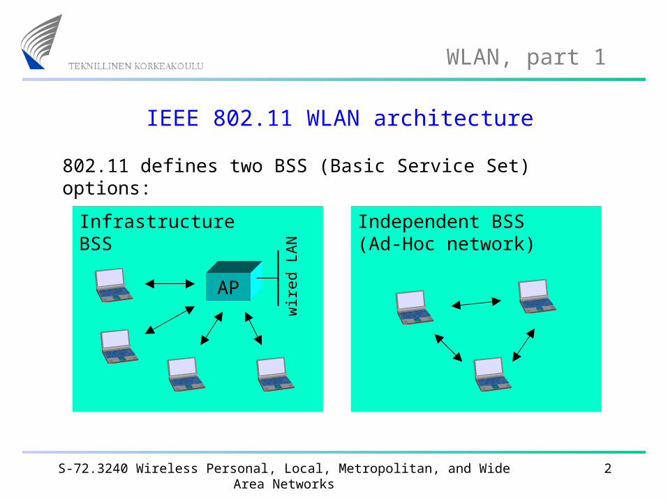
This is by far the most common way of implementing WLANs.
Infrastructure BSS
AP
The base stations connected to the wired infrastructure are called access points (AP).
Wireless stations in an Infrastructure BSS must always communicate via the AP (never directly).
Before stations can use the BSS: Association.
wir
ed L
AN
S-72.3240 Wireless Personal, Local, Metropolitan, and Wide Area Networks 4
WLAN, part 1
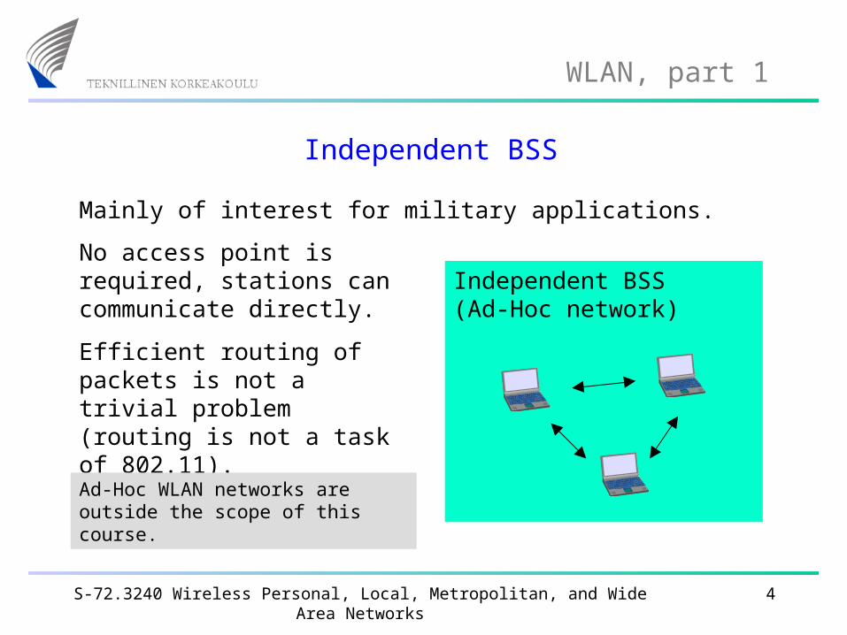
Independent BSS
Mainly of interest for military applications.
Independent BSS(Ad-Hoc network)
No access point is required, stations can communicate directly.
Efficient routing of packets is not a trivial problem(routing is not a task of 802.11).
Ad-Hoc WLAN networks are outside the scope of this course.
S-72.3240 Wireless Personal, Local, Metropolitan, and Wide Area Networks 5
WLAN, part 1
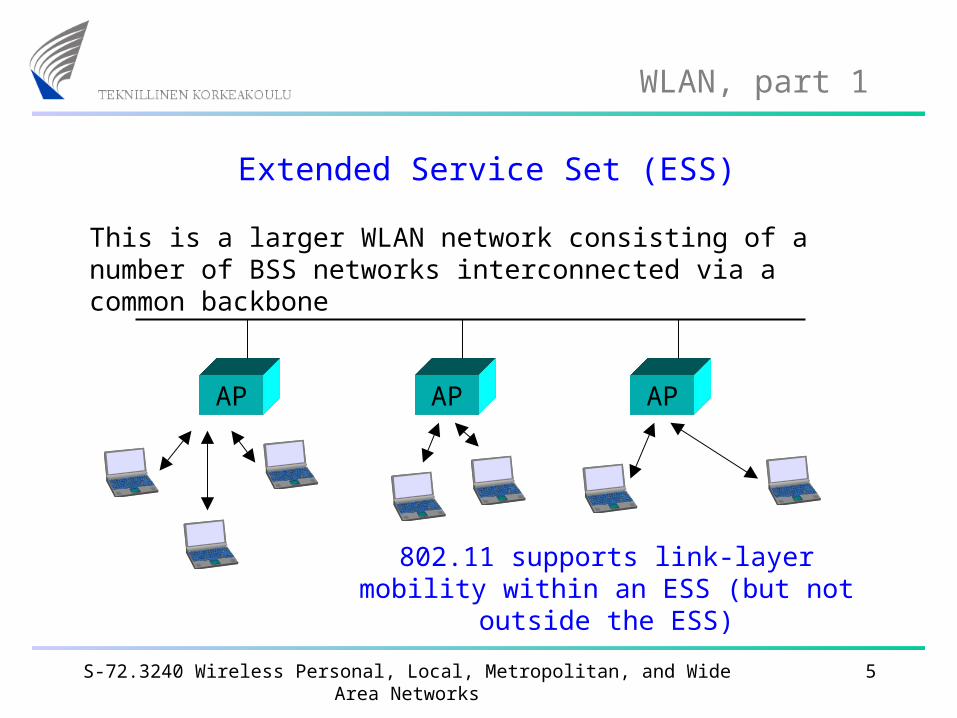
Extended Service Set (ESS)
This is a larger WLAN network consisting of a number of BSS networks interconnected via a common backbone
AP AP AP
802.11 supports link-layer mobility within an ESS (but not outside the ESS)
S-72.3240 Wireless Personal, Local, Metropolitan, and Wide Area Networks 6
WLAN, part 1
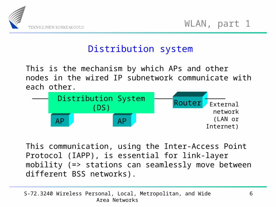
Distribution system
This is the mechanism by which APs and other nodes in the wired IP subnetwork communicate with each other.
AP AP
RouterDistribution System (DS)
This communication, using the Inter-Access Point Protocol (IAPP), is essential for link-layer mobility (=> stations can seamlessly move between different BSS networks).
External network (LAN or
Internet)
S-72.3240 Wireless Personal, Local, Metropolitan, and Wide Area Networks 7
WLAN, part 1
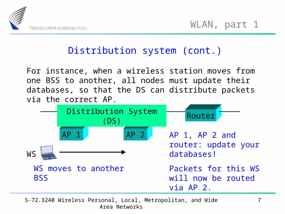
Distribution system (cont.)
For instance, when a wireless station moves from one BSS to another, all nodes must update their databases, so that the DS can distribute packets via the correct AP.
AP 1 AP 2
Router
WS
AP 1, AP 2 and router: update your databases!
Packets for this WS will now be routed via AP 2.
Distribution System (DS)
WS moves to another BSS
S-72.3240 Wireless Personal, Local, Metropolitan, and Wide Area Networks 8
WLAN, part 1
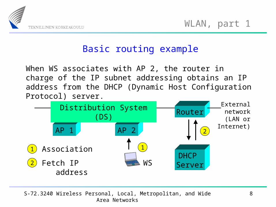
Basic routing example
When WS associates with AP 2, the router in charge of the IP subnet addressing obtains an IP address from the DHCP (Dynamic Host Configuration Protocol) server.
Router
AP 1 AP 2
Distribution System (DS)
DHCP Server
Association
Fetch IP address
1
2
1
2
External network (LAN or
Internet)
WS
S-72.3240 Wireless Personal, Local, Metropolitan, and Wide Area Networks 9
WLAN, part 1
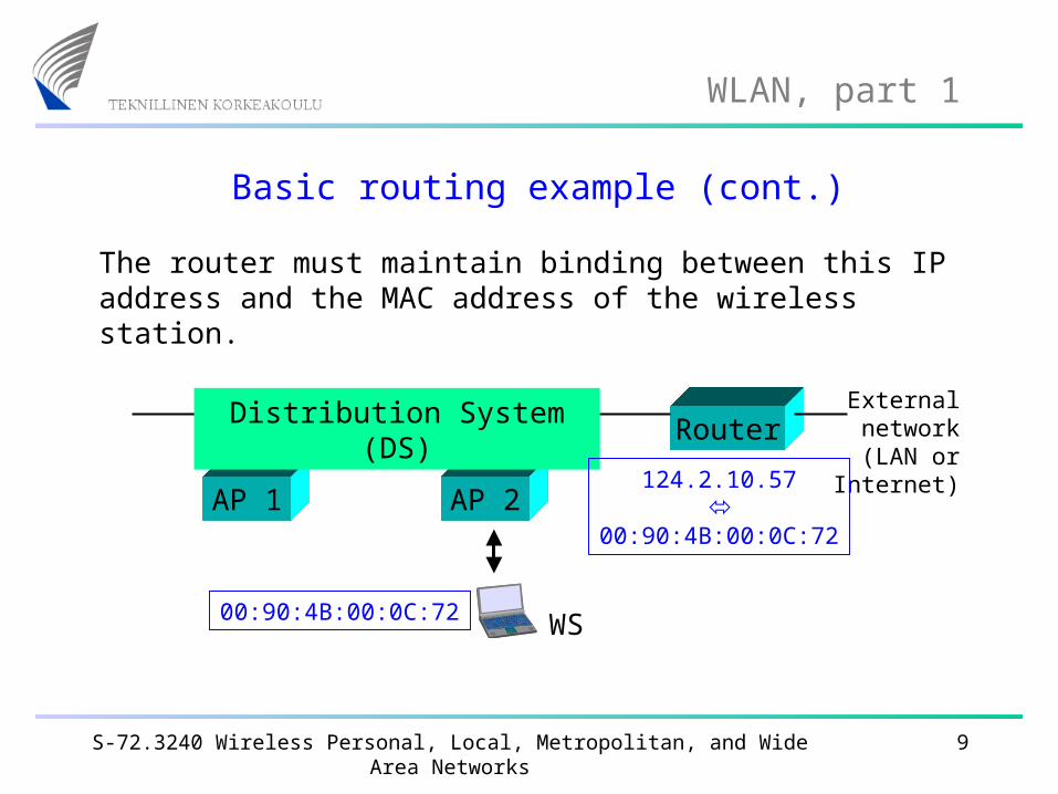
Basic routing example (cont.)
The router must maintain binding between this IP address and the MAC address of the wireless station.
Router
AP 1 AP 2
Distribution System (DS) External network (LAN or
Internet)124.2.10.57
00:90:4B:00:0C:72
00:90:4B:00:0C:72 WS
S-72.3240 Wireless Personal, Local, Metropolitan, and Wide Area Networks 10
WLAN, part 1
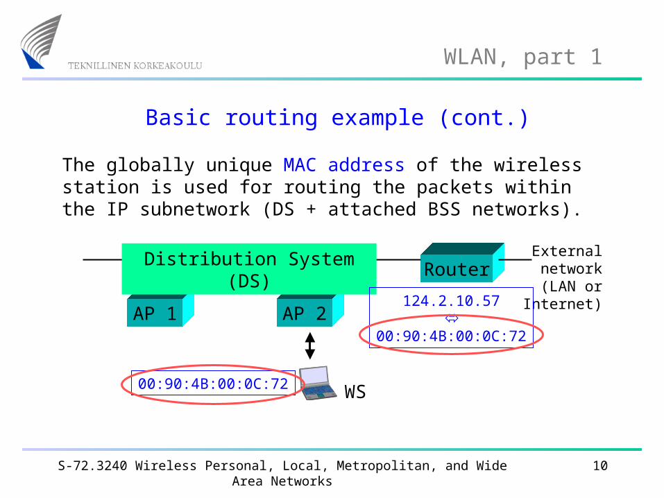
Basic routing example (cont.)
The globally unique MAC address of the wireless station is used for routing the packets within the IP subnetwork (DS + attached BSS networks).
Router
AP 1 AP 2
Distribution System (DS) External network (LAN or
Internet)124.2.10.57
00:90:4B:00:0C:72
00:90:4B:00:0C:72 WS
S-72.3240 Wireless Personal, Local, Metropolitan, and Wide Area Networks 11
WLAN, part 1
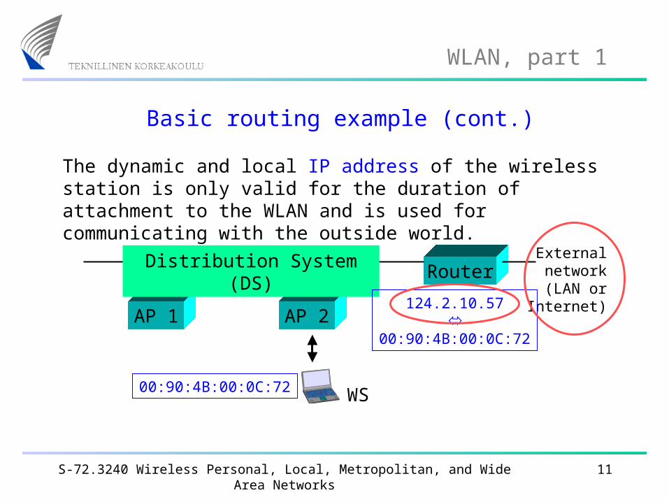
Basic routing example (cont.)
The dynamic and local IP address of the wireless station is only valid for the duration of attachment to the WLAN and is used for communicating with the outside world.
Router
AP 1 AP 2
Distribution System (DS) External network (LAN or
Internet)124.2.10.57
00:90:4B:00:0C:72
00:90:4B:00:0C:72 WS
S-72.3240 Wireless Personal, Local, Metropolitan, and Wide Area Networks 12
WLAN, part 1
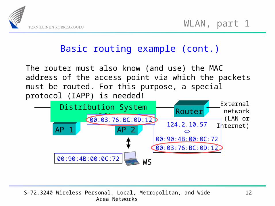
Basic routing example (cont.)
The router must also know (and use) the MAC address of the access point via which the packets must be routed. For this purpose, a special protocol (IAPP) is needed!
Router
AP 1 AP 2
Distribution System (DS) External network (LAN or
Internet)124.2.10.57
00:90:4B:00:0C:7200:03:76:BC:0D:12
00:90:4B:00:0C:72
00:03:76:BC:0D:12
WS
S-72.3240 Wireless Personal, Local, Metropolitan, and Wide Area Networks 13
WLAN, part 1
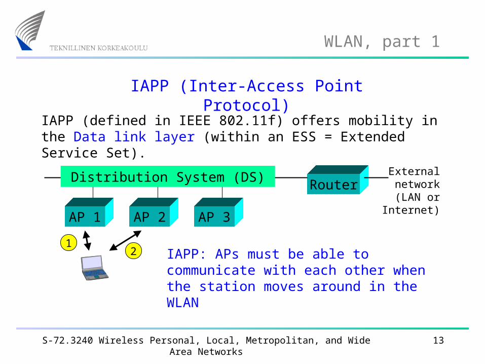
IAPP (Inter-Access Point Protocol)
IAPP (defined in IEEE 802.11f) offers mobility in the Data link layer (within an ESS = Extended Service Set).
Router
AP 1 AP 3
Distribution System (DS) External network (LAN or
Internet)AP 2
IAPP: APs must be able to communicate with each other when the station moves around in the WLAN
12
S-72.3240 Wireless Personal, Local, Metropolitan, and Wide Area Networks 14
WLAN, part 1
In addition to IAPP …
IAPP alone is not sufficient to enable seamless handovers in a WLAN. The stations must be able to measure the signal strengths from surrounding APs and decide when and to which AP a handover should be performed (no 802.11 standardised solutions are available for this operation).
In 802.11 networks, a handover means reassociating with the new AP. There may be two kinds of problems:
• will handover work when APs are from different vendors?
• will handover work together with security solutions?
S-72.3240 Wireless Personal, Local, Metropolitan, and Wide Area Networks 15
WLAN, part 1
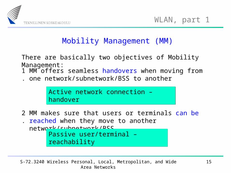
Mobility Management (MM)
There are basically two objectives of Mobility Management:
MM offers seamless handovers when moving from one network/subnetwork/BSS to another
MM makes sure that users or terminals can be reached when they move to another network/subnetwork/BSS
1.
2.
Active network connection – handover Active network connection – handover
Passive user/terminal – reachabilityPassive user/terminal – reachability
S-72.3240 Wireless Personal, Local, Metropolitan, and Wide Area Networks 16
WLAN, part 1
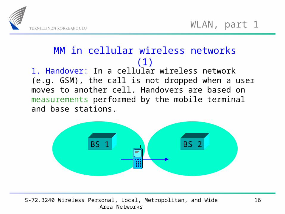
MM in cellular wireless networks (1)
1. Handover: In a cellular wireless network (e.g. GSM), the call is not dropped when a user moves to another cell. Handovers are based on measurements performed by the mobile terminal and base stations.
BS 1 BS 2
S-72.3240 Wireless Personal, Local, Metropolitan, and Wide Area Networks 17
WLAN, part 1
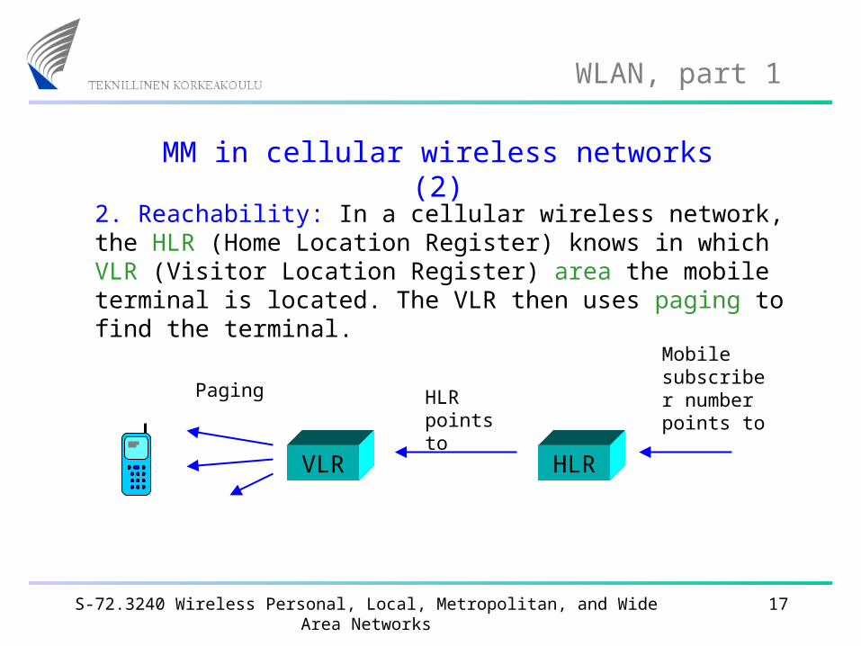
MM in cellular wireless networks (2)
VLR HLR
2. Reachability: In a cellular wireless network, the HLR (Home Location Register) knows in which VLR (Visitor Location Register) area the mobile terminal is located. The VLR then uses paging to find the terminal.
Mobile subscriber number points to
HLR points to
Paging
S-72.3240 Wireless Personal, Local, Metropolitan, and Wide Area Networks 18
WLAN, part 1
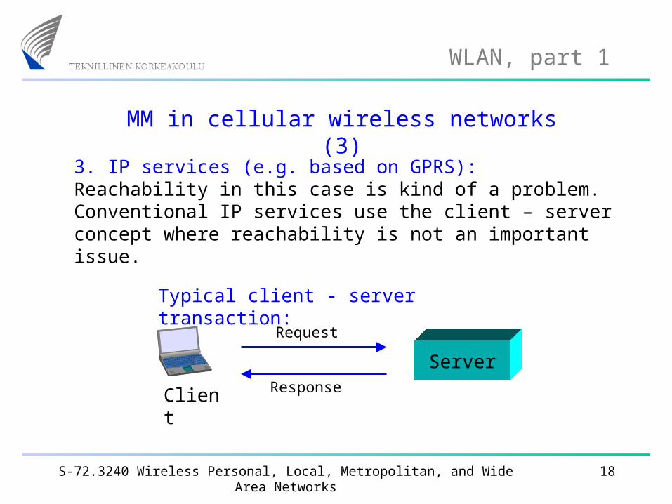
MM in cellular wireless networks (3)
3. IP services (e.g. based on GPRS): Reachability in this case is kind of a problem. Conventional IP services use the client – server concept where reachability is not an important issue.
Server
Client
Request
Response
Typical client - server transaction:
S-72.3240 Wireless Personal, Local, Metropolitan, and Wide Area Networks 19
WLAN, part 1
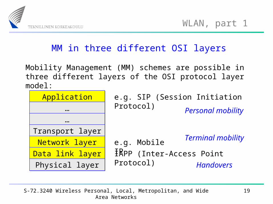
MM in three different OSI layers
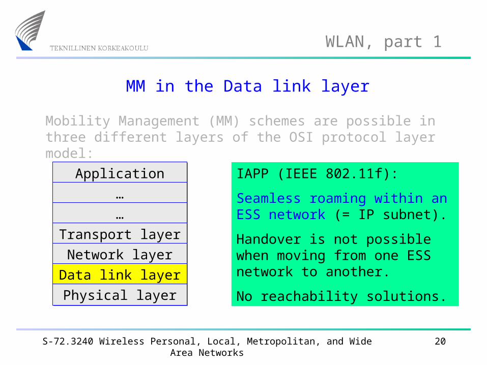
Mobility Management (MM) schemes are possible in three different layers of the OSI protocol layer model:
Application layerApplication layer
……
……
Transport layerTransport layer
Network layerNetwork layer
Data link layerData link layer
Physical layerPhysical layer
e.g. SIP (Session Initiation Protocol)
e.g. Mobile IP
IAPP (Inter-Access Point Protocol)
Terminal mobility
Personal mobility
Handovers
S-72.3240 Wireless Personal, Local, Metropolitan, and Wide Area Networks 20
WLAN, part 1
MM in the Data link layer
Mobility Management (MM) schemes are possible in three different layers of the OSI protocol layer model:
Application layerApplication layer
……
……
Transport layerTransport layer
Network layerNetwork layer
Data link layerData link layer
Physical layerPhysical layer
IAPP (IEEE 802.11f):
Seamless roaming within an ESS network (= IP subnet).
Handover is not possible when moving from one ESS network to another.
No reachability solutions.
S-72.3240 Wireless Personal, Local, Metropolitan, and Wide Area Networks 21
WLAN, part 1
MM in the Network layer
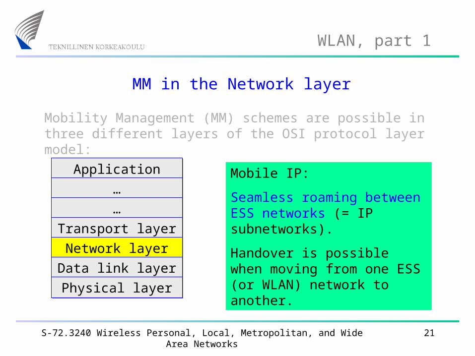
Mobility Management (MM) schemes are possible in three different layers of the OSI protocol layer model:
Application layerApplication layer
……
……
Transport layerTransport layer
Network layerNetwork layer
Data link layerData link layer
Physical layerPhysical layer
Mobile IP:
Seamless roaming between ESS networks (= IP subnetworks).
Handover is possible when moving from one ESS (or WLAN) network to another.
S-72.3240 Wireless Personal, Local, Metropolitan, and Wide Area Networks 22
WLAN, part 1
MM in the Application layer
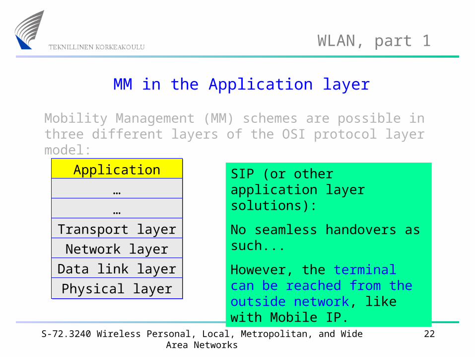
Mobility Management (MM) schemes are possible in three different layers of the OSI protocol layer model:
Application layerApplication layer
……
……
Transport layerTransport layer
Network layerNetwork layer
Data link layerData link layer
Physical layerPhysical layer
SIP (or other application layer solutions):
No seamless handovers as such...
However, the terminal can be reached from the outside network, like with Mobile IP.
S-72.3240 Wireless Personal, Local, Metropolitan, and Wide Area Networks 23
WLAN, part 1
Mobility management summary
Within a WLAN, handovers are possible (based on IAPP + proprietary solutions in equipment), but there is no IEEE-supported reachability solution available.
Handovers between different WLANs require Mobile IP (which offers also reachability). Unfortunately, Mobile IP includes a non-transparent mechanism (Discovering Care-of Address) that must be implemented in all APs.
Global reachability of wireless stations can be achieved using SIP or similar Application layer concepts. SIP does not require changes to APs.
S-72.3240 Wireless Personal, Local, Metropolitan, and Wide Area Networks 24
WLAN, part 1
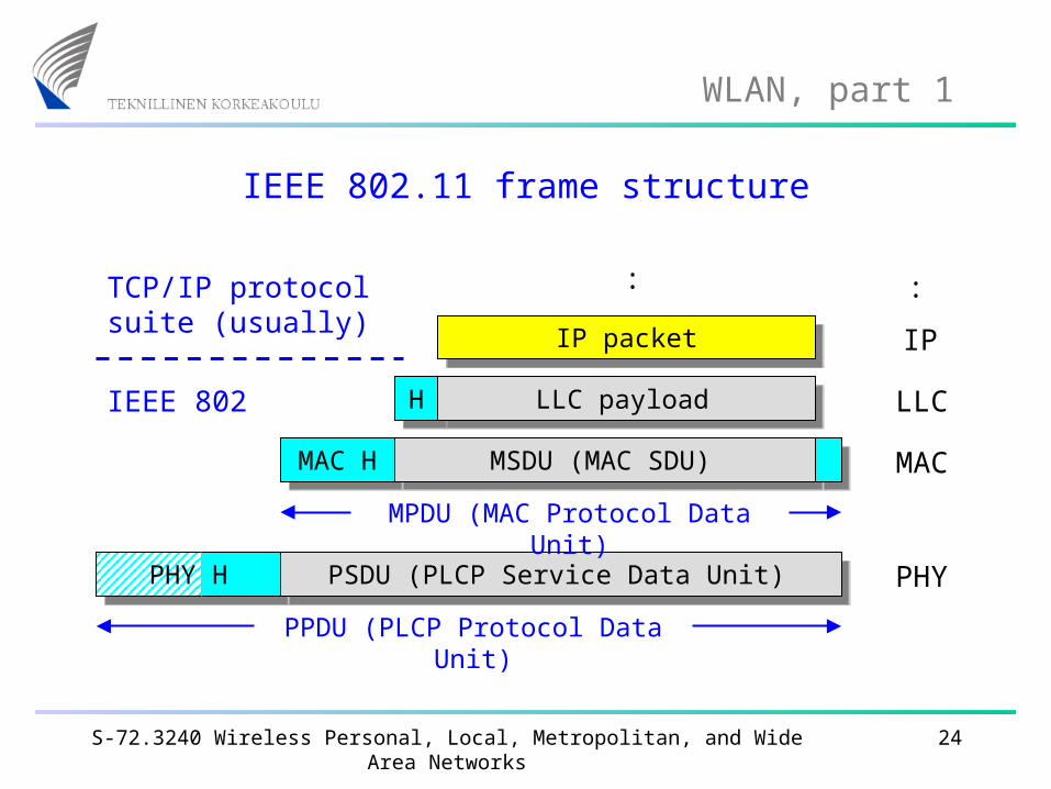
IEEE 802.11 frame structure
PSDU (PLCP Service Data Unit)
MAC H
PHY
MSDU (MAC SDU)
LLC payloadH
MAC
LLC
IP
IEEE 802
PHY H
IP packet
: :TCP/IP protocol suite (usually)
PPDU (PLCP Protocol Data Unit)
MPDU (MAC Protocol Data Unit)
S-72.3240 Wireless Personal, Local, Metropolitan, and Wide Area Networks 25
WLAN, part 1
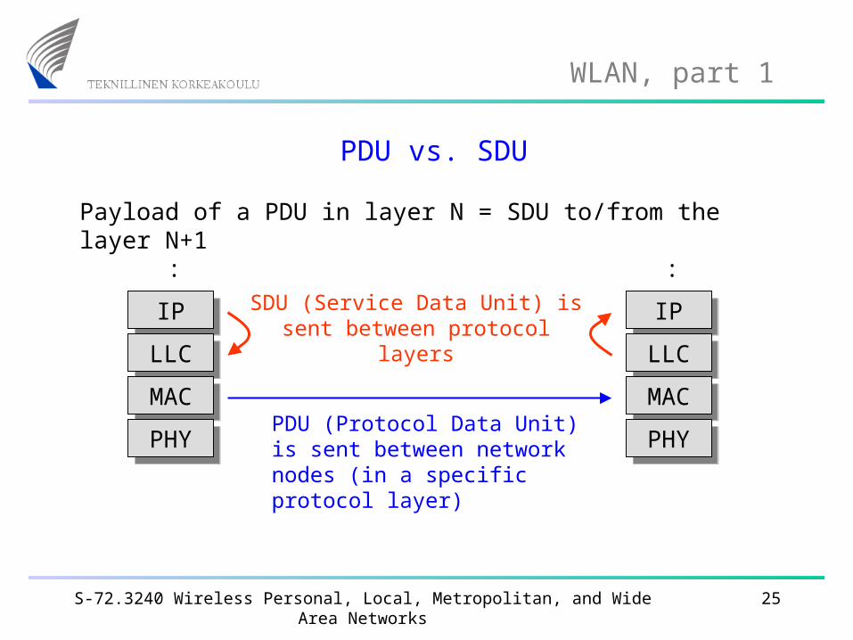
PDU vs. SDU
IPIP
LLCLLC
MACMAC
PHYPHY
:
IPIP
LLCLLC
MACMAC
PHYPHY
:
PDU (Protocol Data Unit) is sent between network nodes (in a specific protocol layer)
SDU (Service Data Unit) is sent between protocol layers
Payload of a PDU in layer N = SDU to/from the layer N+1
S-72.3240 Wireless Personal, Local, Metropolitan, and Wide Area Networks 26
WLAN, part 1
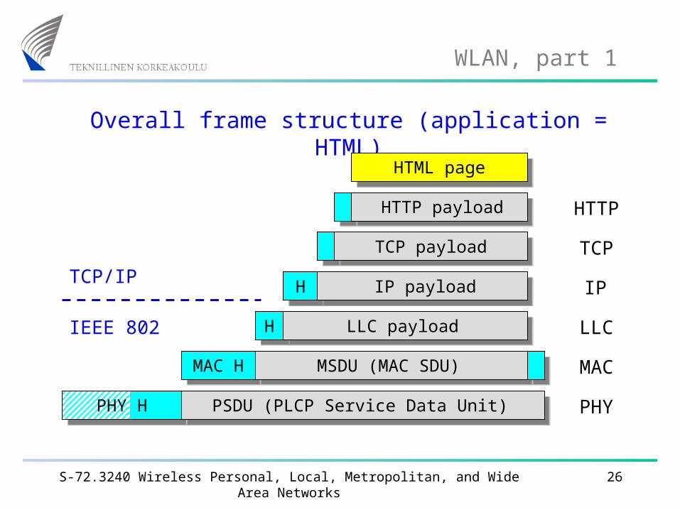
Overall frame structure (application = HTML)
PSDU (PLCP Service Data Unit)
MAC H
PHY
MSDU (MAC SDU)
LLC payloadH
H IP payload
TCP payload
HTTP payload
HTML page
MAC
LLC
IP
TCP
HTTP
IEEE 802
TCP/IP
PHY H
S-72.3240 Wireless Personal, Local, Metropolitan, and Wide Area Networks 27
WLAN, part 1
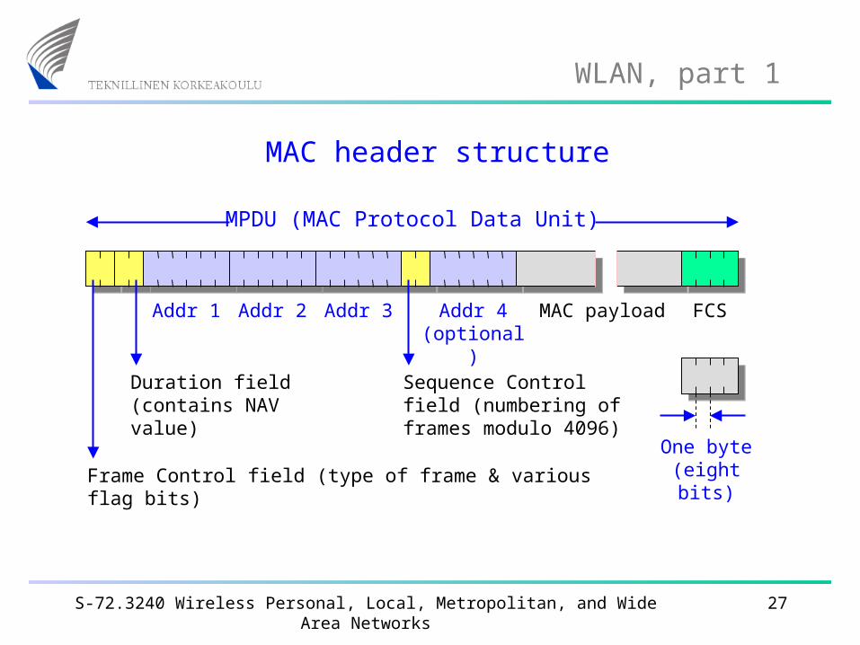
MAC header structure
MPDU (MAC Protocol Data Unit)
MAC payloadAddr 1 Addr 2 Addr 3 Addr 4 (optional)
FCS
Frame Control field (type of frame & various flag bits)
Duration field (contains NAV value)
Sequence Control field (numbering of frames modulo 4096)
One byte (eight bits)
S-72.3240 Wireless Personal, Local, Metropolitan, and Wide Area Networks 28
WLAN, part 1
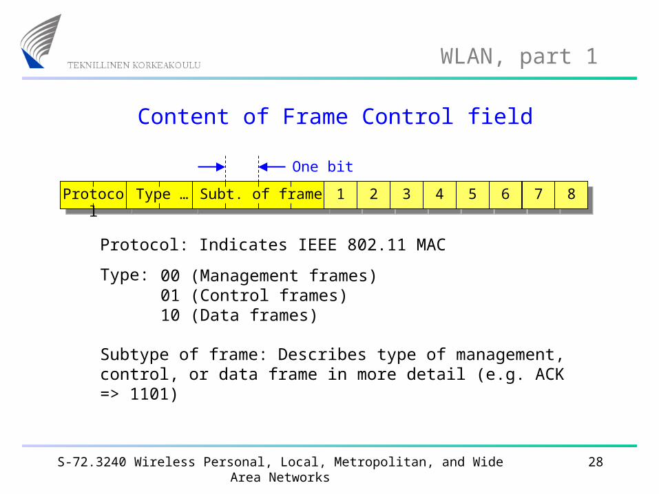
Content of Frame Control field
One bit
1 2 3 4 5 6 7 8Protocol Subt. of frameType …
Protocol: Indicates IEEE 802.11 MAC
Type: 00 (Management frames) 01 (Control frames)10 (Data frames)
Subtype of frame: Describes type of management, control, or data frame in more detail (e.g. ACK => 1101)
S-72.3240 Wireless Personal, Local, Metropolitan, and Wide Area Networks 29
WLAN, part 1
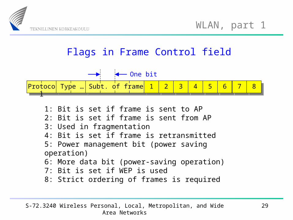
Flags in Frame Control field
One bit
1 2 3 4 5 6 7 8Protocol Subt. of frameType …
1: Bit is set if frame is sent to AP2: Bit is set if frame is sent from AP3: Used in fragmentation4: Bit is set if frame is retransmitted5: Power management bit (power saving operation)6: More data bit (power-saving operation)7: Bit is set if WEP is used8: Strict ordering of frames is required
S-72.3240 Wireless Personal, Local, Metropolitan, and Wide Area Networks 30
WLAN, part 1
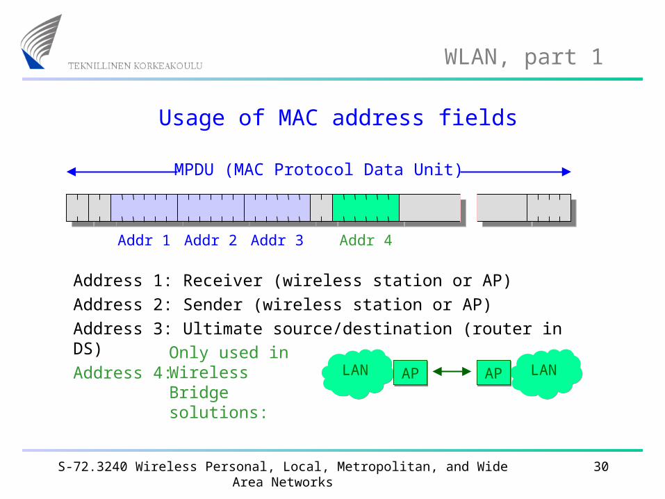
Usage of MAC address fields
MPDU (MAC Protocol Data Unit)
Addr 1 Addr 2 Addr 3 Addr 4
Address 1: Receiver (wireless station or AP)Address 2: Sender (wireless station or AP)Address 3: Ultimate source/destination (router in DS)Address 4: Only used in
Wireless Bridge solutions:
LANLAN LANLANAPAP APAP
S-72.3240 Wireless Personal, Local, Metropolitan, and Wide Area Networks 31
WLAN, part 1
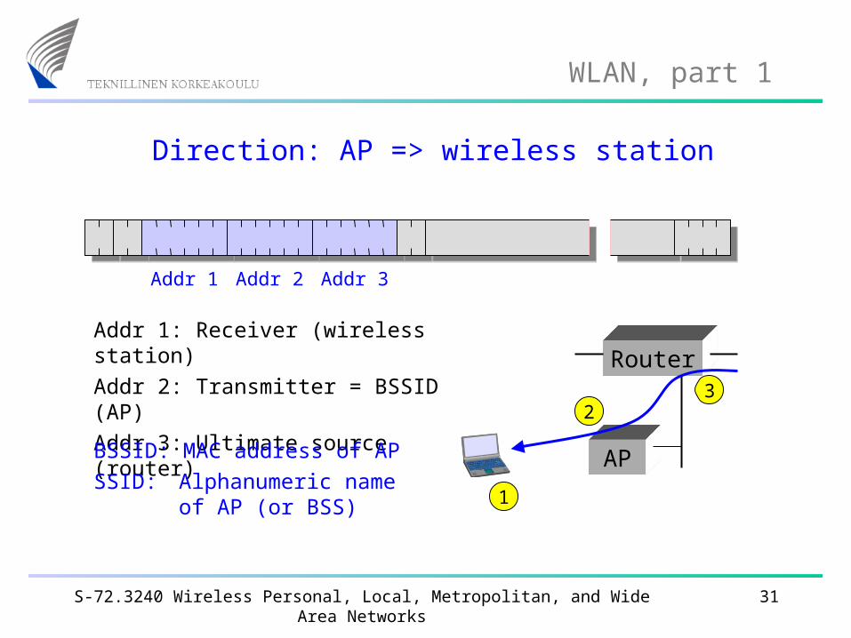
Direction: AP => wireless station
Addr 1 Addr 2 Addr 3
Addr 1: Receiver (wireless station)Addr 2: Transmitter = BSSID (AP)Addr 3: Ultimate source (router)
AP
Router
BSSID: MAC address of APSSID: Alphanumeric name
of AP (or BSS) 1
23
S-72.3240 Wireless Personal, Local, Metropolitan, and Wide Area Networks 32
WLAN, part 1
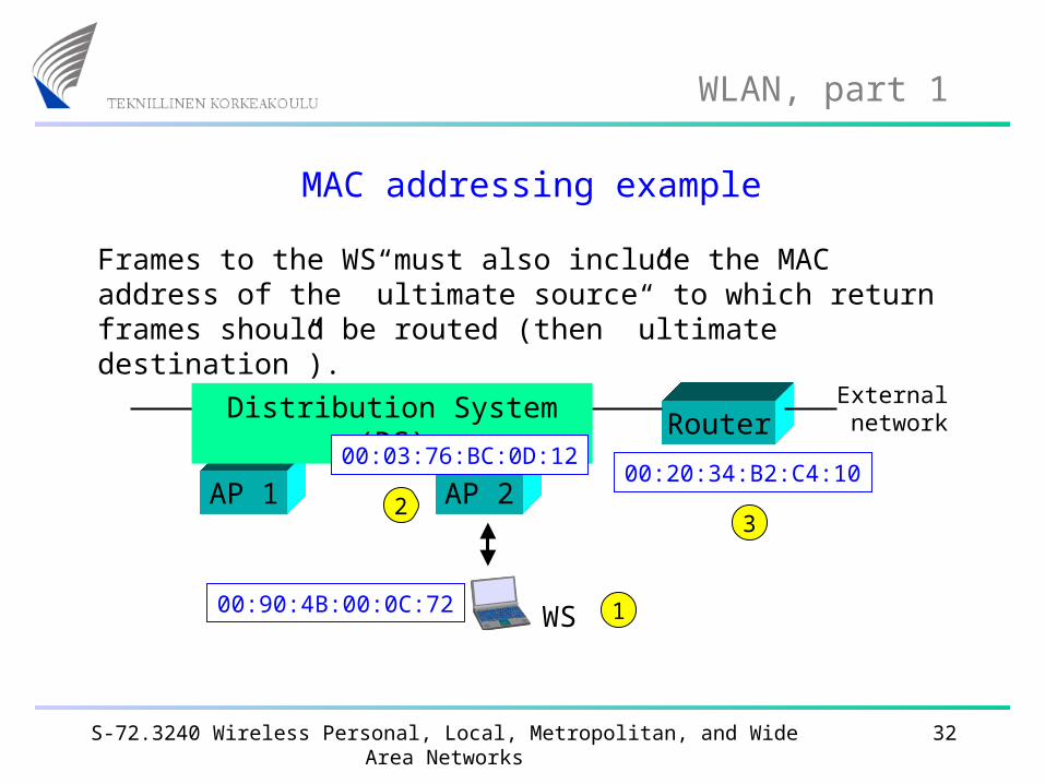
MAC addressing example
Frames to the WS must also include the MAC address of the ”ultimate source” to which return frames should be routed (then ”ultimate destination”).
Router
AP 1 AP 2
Distribution System (DS) External network
00:20:34:B2:C4:10
00:90:4B:00:0C:72
00:03:76:BC:0D:12
WS 1
23
S-72.3240 Wireless Personal, Local, Metropolitan, and Wide Area Networks 33
WLAN, part 1
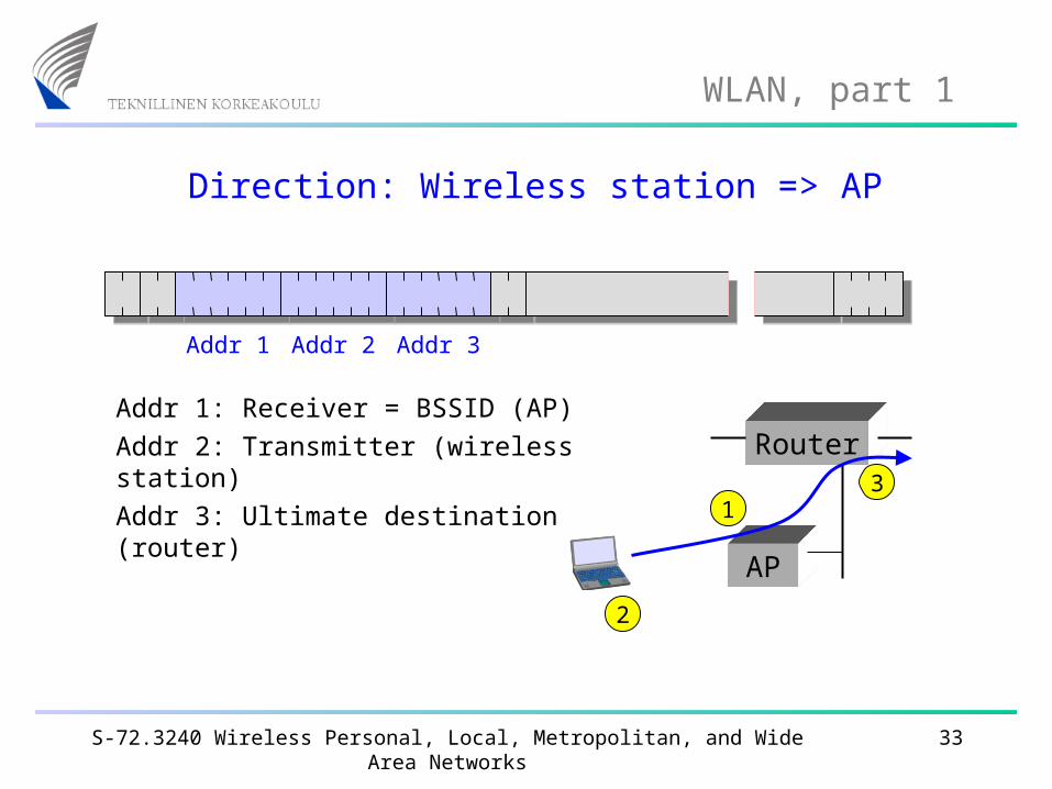
Direction: Wireless station => AP
Addr 1 Addr 2 Addr 3
Addr 1: Receiver = BSSID (AP)Addr 2: Transmitter (wireless station)Addr 3: Ultimate destination (router)
AP
Router
2
13
S-72.3240 Wireless Personal, Local, Metropolitan, and Wide Area Networks 34
WLAN, part 1
Management frames
In addition to the data frames (containing the user data to be transported over the 802.11 network) and control frames (e.g. acknowledgements), there are a number of management frames.
Note that these management frames compete for access to the medium in equal terms (using CSMA/CA) with the data and control frames.
Some of these management frames are presented on the following slides.
S-72.3240 Wireless Personal, Local, Metropolitan, and Wide Area Networks 35
WLAN, part 1
Beacon frames
Beacon frames are broadcast (mening that all stations shall receive them and read the information) at regular intervals from the Access Point. These frames contain (among others) the following information:
Timestamp (8 bytes) is necessary, so that stations can synchronise to the network
Beacon interval (2 bytes) in milliseconds
Capability info (2 bytes) advertises network capabilities
SSID (0 ... 32 bytes), alphanumeric “network name”
The channel number used by the network (optional).
S-72.3240 Wireless Personal, Local, Metropolitan, and Wide Area Networks 36
WLAN, part 1
Probe request & response frames
A probe request frame is transmitted from a wireless station during active scanning. Access points within reach respond by sending probe response frames.
Probe request frames contain the following information:
SSID (0 ... 32 bytes), alphanumeric “network name”
Bit rates supported by the station. This is used by APs to see if the station can be permitted to join the network.
Probe response frames actually contain the same kind of “network information” as beacon frames.
S-72.3240 Wireless Personal, Local, Metropolitan, and Wide Area Networks 37
WLAN, part 1
Association request & response frames
Before a station can join an 802.11 network, it must send an association request frame. The AP responds with an association response frame.
Association request frames contain (among others):
SSID, capability info, bit rates supported.
Association response frames contain (among others):
Capability info, bit rates supported
Status code (success or failure with failure cause)
Association ID (used for various purposes)
S-72.3240 Wireless Personal, Local, Metropolitan, and Wide Area Networks 38
WLAN, part 1
Passive and active scanning
Wireless stations can find out about 802.11 networks by using passive or active scanning.
During passive scanning, the station searches beacon frames, moving from channel to channel through the complete channel set (802.11b => 13 channels).
During active scanning, the station selects Channel 1 and sends a probe request frame. If no probe response frame is received within a certain time, the station moves to Channel 2 and sends a probe request frame, and so on.
S-72.3240 Wireless Personal, Local, Metropolitan, and Wide Area Networks 39
WLAN, part 1
Case study 1: Station connecting to a WLAN
When a station moves into the coverage area of a WLAN, the following procedures take place:
1) Scanning: the station searches for a suitable channel over which subsequent communication takes place
2)
3)
4)
Association: the station associates with an AP
IP address allocation: the station gets an IP address, for instance from a DHCP server
Authentication: only if this security option is required.
S-72.3240 Wireless Personal, Local, Metropolitan, and Wide Area Networks 40
WLAN, part 1
Case study 2: Handover to another AP
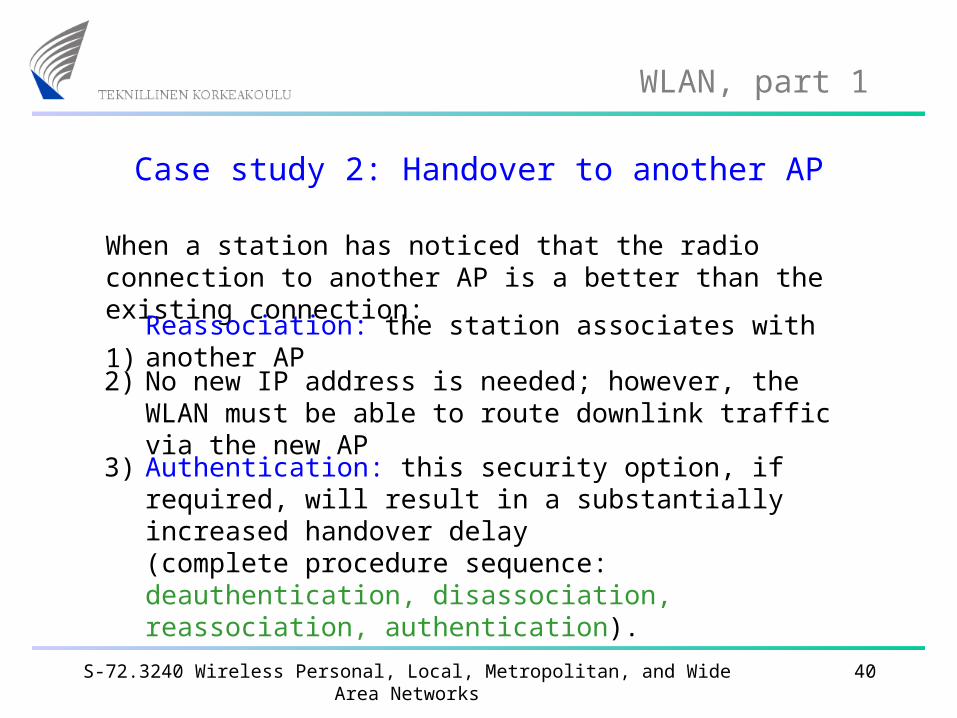
When a station has noticed that the radio connection to another AP is a better than the existing connection:
1) Reassociation: the station associates with another AP
2) No new IP address is needed; however, the WLAN must be able to route downlink traffic via the new AP
3) Authentication: this security option, if required, will result in a substantially increased handover delay (complete procedure sequence: deauthentication, disassociation, reassociation, authentication).
S-72.3240 Wireless Personal, Local, Metropolitan, and Wide Area Networks 41
WLAN, part 1
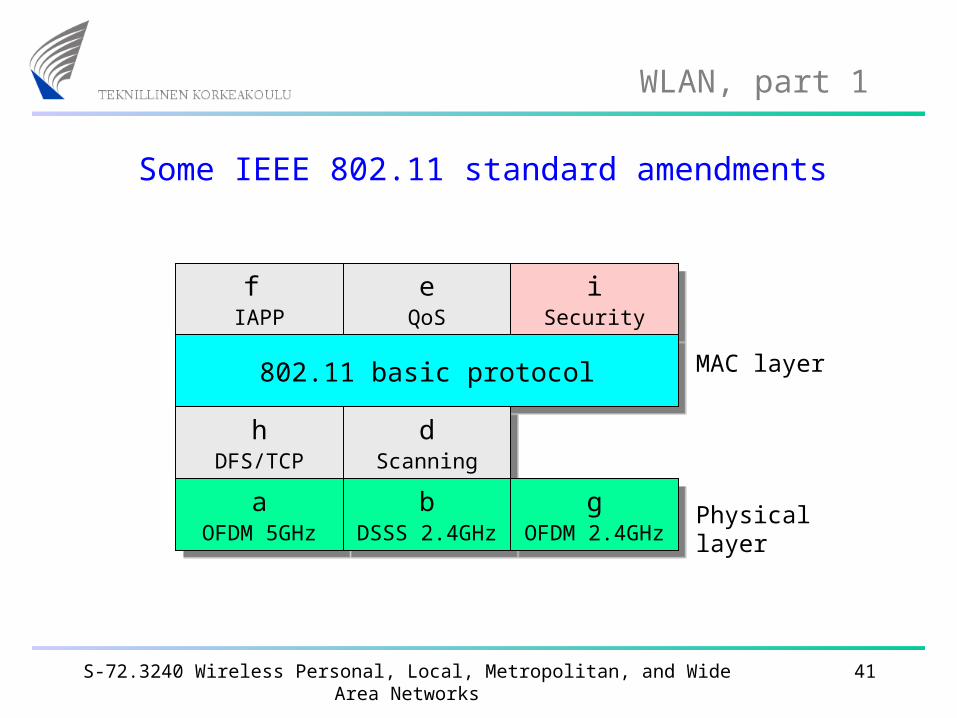
Some IEEE 802.11 standard amendments
f IAPP
f IAPP
eQoS
eQoS
iSecurity
iSecurity
802.11 basic protocol802.11 basic protocol
hDFS/TCP
hDFS/TCP
dScanning
dScanning
aOFDM 5GHz
aOFDM 5GHz
bDSSS 2.4GHz
bDSSS 2.4GHz
gOFDM 2.4GHz
gOFDM 2.4GHz
Physical layer
MAC layer
S-72.3240 Wireless Personal, Local, Metropolitan, and Wide Area Networks 42
WLAN, part 1
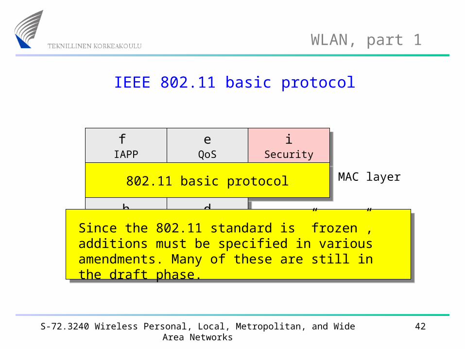
IEEE 802.11 basic protocol
f IAPP
f IAPP
eQoS
eQoS
iSecurity
iSecurity
802.11 basic protocol802.11 basic protocol
hDFS/TCP
hDFS/TCP
dScanning
dScanning
aOFDM 5GHz
aOFDM 5GHz
bDSSS 2.4GHz
bDSSS 2.4GHz
gOFDM 2.4GHz
gOFDM 2.4GHz
MAC layer
Since the 802.11 standard is ”frozen”, additions must be specified in various amendments. Many of these are still in the draft phase.
S-72.3240 Wireless Personal, Local, Metropolitan, and Wide Area Networks 43
WLAN, part 1
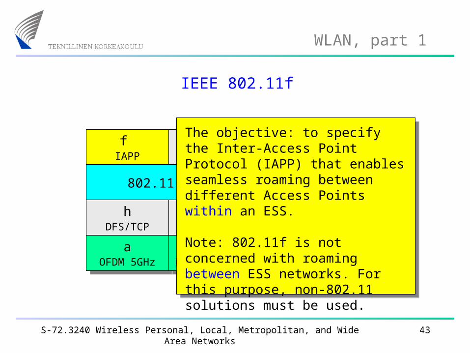
IEEE 802.11f
f IAPP
f IAPP
eQoS
eQoS
iSecurity
iSecurity
802.11 basic protocol802.11 basic protocol
hDFS/TCP
hDFS/TCP
dScanning
dScanning
aOFDM 5GHz
aOFDM 5GHz
bDSSS 2.4GHz
bDSSS 2.4GHz
gOFDM 2.4GHz
gOFDM 2.4GHz
The objective: to specify the Inter-Access Point Protocol (IAPP) that enables seamless roaming between different Access Points within an ESS.
Note: 802.11f is not concerned with roaming between ESS networks. For this purpose, non-802.11 solutions must be used.
S-72.3240 Wireless Personal, Local, Metropolitan, and Wide Area Networks 44
WLAN, part 1
IEEE 802.11e
f IAPP
f IAPP
eQoS
eQoS
iSecurity
iSecurity
802.11 basic protocol802.11 basic protocol
hDFS/TCP
hDFS/TCP
dScanning
dScanning
aOFDM 5GHz
aOFDM 5GHz
bDSSS 2.4GHz
bDSSS 2.4GHz
gOFDM 2.4GHz
gOFDM 2.4GHz
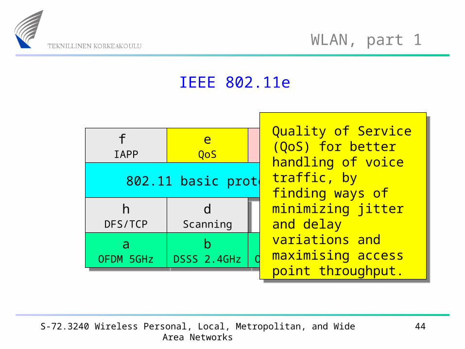
Quality of Service (QoS) for better handling of voice traffic, by finding ways of minimizing jitter and delay variations and maximising access point throughput.
S-72.3240 Wireless Personal, Local, Metropolitan, and Wide Area Networks 45
WLAN, part 1
IEEE 802.11i
f IAPP
f IAPP
eQoS
eQoS
iSecurity
iSecurity
802.11 basic protocol802.11 basic protocol
hDFS/TCP
hDFS/TCP
dScanning
dScanning
aOFDM 5GHz
aOFDM 5GHz
bDSSS 2.4GHz
bDSSS 2.4GHz
gOFDM 2.4GHz
gOFDM 2.4GHz
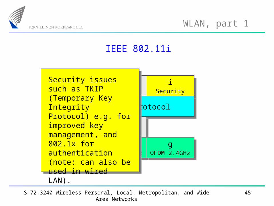
Security issues such as TKIP (Temporary Key Integrity Protocol) e.g. for improved key management, and 802.1x for authentication (note: can also be used in wired LAN).
S-72.3240 Wireless Personal, Local, Metropolitan, and Wide Area Networks 46
WLAN, part 1
IEEE 802.11h
f IAPP
f IAPP
eQoS
eQoS
iSecurity
iSecurity
802.11 basic protocol802.11 basic protocol
hDFS/TCP
hDFS/TCP
dScanning
dScanning
aOFDM 5GHz
aOFDM 5GHz
bDSSS 2.4GHz
bDSSS 2.4GHz
gOFDM 2.4GHz
gOFDM 2.4GHz
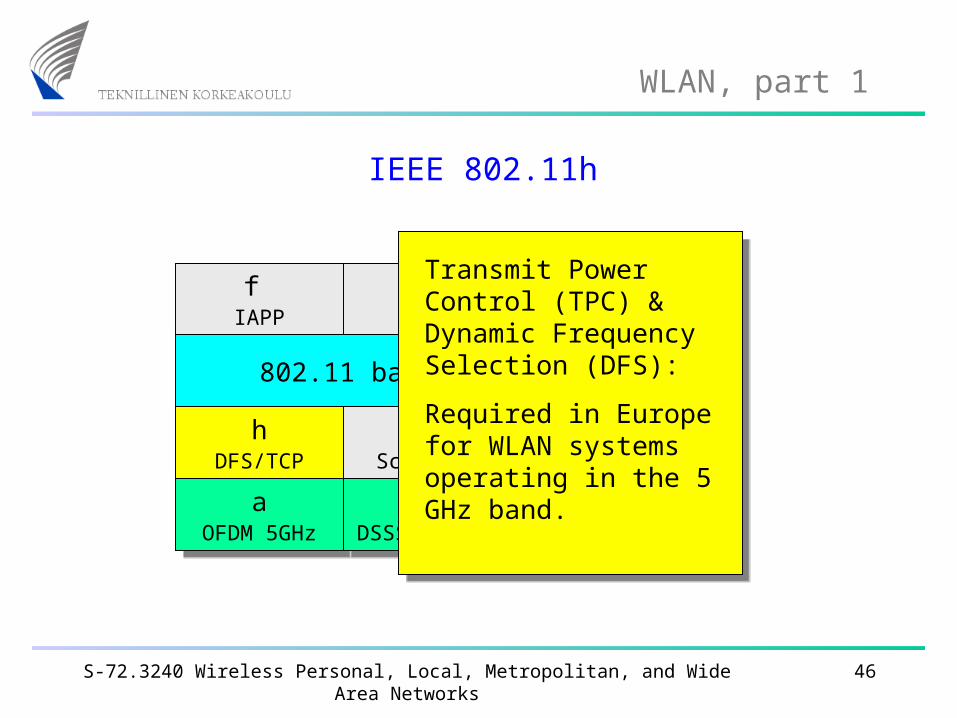
Transmit Power Control (TPC) & Dynamic Frequency Selection (DFS):
Required in Europe for WLAN systems operating in the 5 GHz band.
S-72.3240 Wireless Personal, Local, Metropolitan, and Wide Area Networks 47
WLAN, part 1
IEEE 802.11d
f IAPP
f IAPP
eQoS
eQoS
iSecurity
iSecurity
802.11 basic protocol802.11 basic protocol
hDFS/TCP
hDFS/TCP
dScanning
dScanning
aOFDM 5GHz
aOFDM 5GHz
bDSSS 2.4GHz
bDSSS 2.4GHz
gOFDM 2.4GHz
gOFDM 2.4GHz
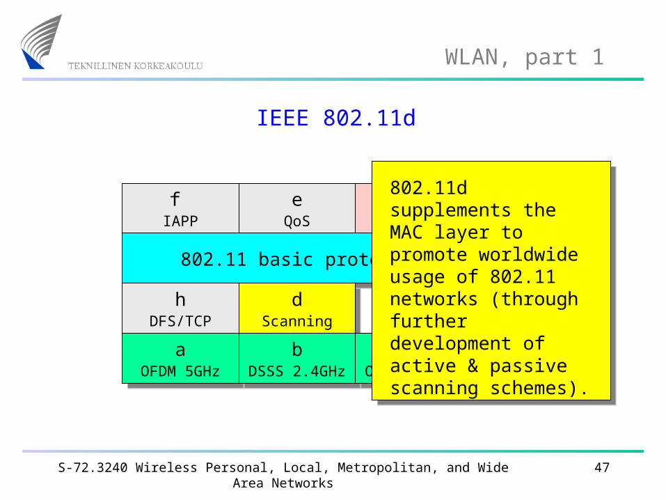
802.11d supplements the MAC layer to promote worldwide usage of 802.11 networks (through further development of active & passive scanning schemes).