Embed Size (px)
Citation preview

WHITEMOUNTAINAPACHE TRIBE
WMATRuralWaterSystem
30%DesignStatementofWork
9/16/2011

TABLE OF CONTENTS
WMAT RURAL WATER SYSTEM
PUBLIC LAW 111‐291, TITLE III
30% DESIGN
MINER FLAT DAM
WATER TREATMENT PLAN
DISTRIBUTION SYSTEM

Miner Flat Rural Water Project Table of Contents
iii
Table of Contents
1. Miner Flat Dam and Storage Reservoir .......................................................................... 1
1.1. Table of Deliverables ........................................................................................................ 1
1.2. Pre-Design Data Studies, Coordination and Data Collection ........................................... 3
1.2.1. Preliminary Dam Site Study .................................................................................. 3 1.2.2. Special Coordination .............................................................................................. 4 1.2.3. Data Collection ...................................................................................................... 4 1.2.4. Reservoir Seepage .................................................................................................. 6 1.2.5. Seismotectonic Studies .......................................................................................... 6
1.3. Dam Design and Analysis ................................................................................................ 8
1.3.1. Dam Design ............................................................................................................ 8 1.3.2. Dam Analysis ......................................................................................................... 9 1.3.3. Geology .................................................................................................................. 9 1.3.4. Foundation ........................................................................................................... 12 1.3.5. Grouting ............................................................................................................... 13 1.3.6. Spillway ............................................................................................................... 15 1.3.7. Outlet Works ........................................................................................................ 16 1.3.8. Outlet Works Control House ................................................................................ 16 1.3.9. Diversion during Construction ............................................................................. 16 1.3.10. Electrical .............................................................................................................. 17 1.3.11. Mechanical - Outlet Works .................................................................................. 18 1.3.12. Mechanical – Spillway ......................................................................................... 21 1.3.13. Miscellaneous Metalwork ..................................................................................... 21 1.3.14. Instrumentation..................................................................................................... 22 1.3.15. Access Roads........................................................................................................ 22 1.3.16. Hydroelectric Powerplant Evaluation .................................................................. 23
1.4. Dam Specifications Paragraphs ...................................................................................... 23
1.4.1. Master Format ...................................................................................................... 23 1.4.2. Section Format ..................................................................................................... 23
1.5. Design Drawings ............................................................................................................ 24
1.5.1. General ................................................................................................................. 24 1.5.2. AutoCAD ............................................................................................................. 24
1.6. Construction Cost Estimates ........................................................................................... 24
1.6.1. 30% Design Level Cost Estimate ......................................................................... 24
1.7. Construction Schedule .................................................................................................... 25
1.7.1. Summary Level .................................................................................................... 25 1.7.2. Software ............................................................................................................... 25
1.8. Constructability Report ................................................................................................... 25
Miner Flat Rural Water Project Table of Contents
iv
2. Miner Flat Water Treatment Plant and Diversion Structure ..................................... 27
2.1. Pre-Design Data Studies and Data Collection ................................................................ 27
2.1.1. General ................................................................................................................. 27 2.1.2. Surveying and Mapping ....................................................................................... 28 2.1.3. Geotechnical Investigations ................................................................................. 28 2.1.4. Hydrology ............................................................................................................ 29 2.1.5. Water Demand ..................................................................................................... 29 2.1.6. Existing Water Quality ......................................................................................... 29
2.2. Water Treatment ............................................................................................................. 30
2.2.1. General ................................................................................................................. 30 2.2.2. Surface Water Quality Regulations ...................................................................... 30 2.2.3. Water Quality Goals ............................................................................................. 30 2.2.4. Technical Memorandum ...................................................................................... 31
2.3. Alternative Analyses and Pilot Studies .......................................................................... 31
2.4. WTP Site Investigation/Evaluation ................................................................................ 31
2.5. Water Treatment Report ................................................................................................. 32
2.6. Water Treatment Plant and Appurtenant Facilities Design ............................................ 32
2.6.1. Treatment Facility Design .................................................................................... 32 2.6.2. Treatment Operation Design ................................................................................ 33 2.6.3. Raw Water Diversion/Delivery Design ............................................................... 34 2.6.4. Clearwell (Storage) Reservoir Design ................................................................. 37 2.6.5. Feasibility Design Report (FDR) ........................................................................ 37 2.6.6. 30% Design Drawings ......................................................................................... 38 2.6.7. Specifications Outline .......................................................................................... 38 2.6.8. Constructability Report ........................................................................................ 38 2.6.9. 30% Construction Cost Estimate ........................................................................ 39
3. Miner Flat Municipal Water Pumping Plants, Pipeline and Storage Tanks ............. 41
3.1. Pre-design Data Studies and Data Collection ................................................................. 41
3.1.1. General ................................................................................................................. 41 3.1.2. Surveying and Mapping ....................................................................................... 42 3.1.3. Geotechnical Investigations ................................................................................. 43 3.1.4. Hydrology ............................................................................................................ 44
3.2. Distribution System Design ............................................................................................ 44
3.2.1. Water Demand and Modeling .............................................................................. 44 3.2.2. Plan and Profile Drawings ................................................................................... 45 3.2.3. Pipe Hydraulics and Transient Analyses ............................................................. 45 3.2.4. Pipelines ............................................................................................................... 46 3.2.5. Pumping Plants .................................................................................................... 48 3.2.6. Storage Reservoirs/Tanks .................................................................................... 48 3.2.7. 30% Feasibility Design Report (FDR) ................................................................. 49

Miner Flat Rural Water Project Table of Contents
v
3.2.8. 30% Design Drawings ......................................................................................... 50 3.2.9. Specifications Outline .......................................................................................... 52 3.2.10. Constructability Report ........................................................................................ 52 3.2.11. Construction Cost Estimate .................................................................................. 52
4. Applicable Codes, Standards and Reference Documents ............................................ 55
4.1. Federal Directives and Guidelines .................................................................................. 55
4.2. Reclamation Engineering Monographs .......................................................................... 55
4.3. ACER* Technical Memoranda ..................................................................................... 55
4.4. Reclamation Design Standards ....................................................................................... 56
4.5. Reclamation and Other Manuals .................................................................................... 56
4.6. RCC Reference Documents ............................................................................................ 57
4.7. Applicable Standards for Concrete and Materials .......................................................... 57
4.8. Applicable Standards for Coatings and Linings ............................................................. 60
4.9. General Research (GR) Reports ..................................................................................... 63
4.10. Life Safety ...................................................................................................................... 63
4.11. Accessibility ................................................................................................................... 63
4.12. Security ........................................................................................................................... 63
4.13. Building – Civil/Structural ............................................................................................. 64
4.14. Building – Mechanical Systems ..................................................................................... 64
4.15. Building – Electrical Systems ......................................................................................... 64
4.16. Additional Reference Documents ................................................................................ 665. Environmental Compliance ................................................................................ 67
White Mountain Apache Tribe Miner Flat Rural Water System
Section 1 – Miner Flat Dam and Storage Reservoir
1
1. Miner Flat Dam and Storage Reservoir
Changes to the scope of work presented in this Section 1 and subsequent Sections
2 through 4 shall be implemented during the course of investigation if the Tribe
and Reclamation agree that a change is warranted to improve the design or
reduce costs of design or construction or eliminate duplicative or necessary work
without impact on the integrity of design or construction.
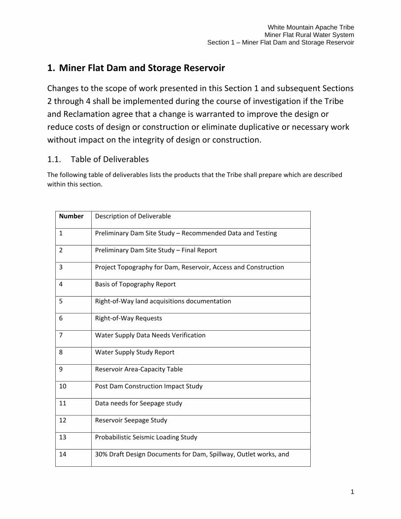
1.1. Table of Deliverables
The following table of deliverables lists the products that the Tribe shall prepare which are described
within this section.
Number Description of Deliverable
1 Preliminary Dam Site Study – Recommended Data and Testing
2 Preliminary Dam Site Study – Final Report
3 Project Topography for Dam, Reservoir, Access and Construction
4 Basis of Topography Report
5 Right‐of‐Way land acquisitions documentation
6 Right‐of‐Way Requests
7 Water Supply Data Needs Verification
8 Water Supply Study Report
9 Reservoir Area‐Capacity Table
10 Post Dam Construction Impact Study
11 Data needs for Seepage study
12 Reservoir Seepage Study
13 Probabilistic Seismic Loading Study
14 30% Draft Design Documents for Dam, Spillway, Outlet works, and

White Mountain Apache Tribe Miner Flat Rural Water System Section 1 – Miner Flat Dam and Storage Reservoir
2
associated features.
15 30% Specifications Drawings and Paragraphs
16 2‐D and 3‐D Structural Analysis Reports
17 30% Surface Geologic Mapping Reports
18 30% Subsurface Geologic Mapping Reports
19 30% Geologic Design Data Report
20 Foundation Exploration Report
21 Rock Stabilization Analysis Report
22 Rock Stabilization Designs, Drawings and Paragraphs
23 Grouting Engineers Resume
24 Grouting Program Report
25 Materials Investigations for Concrete Aggregates Report
26 30% Electrical Designs and Specifications Paragraphs
27 30% Mechanical Designs and Paragraphs for Outlet Works
28 30% Mechanical Designs and Paragraphs for Spillway
29 30% Instrumentation Designs and Paragraphs
30 30% Access Road Designs and Paragraphs
31 30% Construction Cost Estimate
32 30% Construction Schedule
33 Hydroelectric Powerplant Study

White Mountain Apache Tribe Miner Flat Rural Water System
Section 1 – Miner Flat Dam and Storage Reservoir
3
1.2. Pre‐Design Data Studies, Coordination and Data Collection
1.2.1. Preliminary Dam Site Study
The dam site shown and studied in the Project Extension Report (PER) was selected and studied by the Tribe. Due to the nature of the geology for the dam foundation, abutments and proposed reservoir, a stud y of the existing data and previous studies for the current dam site is required. Additionally, identifying, collecting and analyzing additional data to advance the status of knowledge at the site for the proposed dam is required. The study is required to be performed as a first step of the design phase.
The study shall include as a minimum but not be limited to, consideration in the following areas:
The conceptual designs presented in the PER for the dam and reservoir shall be assumed as the design loads to be applied to the foundation and abutments and analyzed for stability and seepage considerations.
The impact of the relatively long left abutment ridge on reservoir seepage and rock slope stability of the ridge on both the upstream and downstream sides.
Potential seepage, consolidation and internal erosion through the paleo‐alluvium zone beneath the dam.
Evaluation of costs for any necessary rock stabilization and seepage treatment for the dam, foundation and reservoir area.
Evaluation of potential Operations and Maintenance issues relative to rock stabilization, monitoring and seepage for the dam site area.
Stability of the foundation and abutments relative to the conceptual designs to overtop the dam for floods greater than a 100‐year recurrence interval flood.
Evaluate the effects of the contacts between different geologic units on stability and seepage.
Evaluate the ability to successfully grout the foundation and abutments to provide reasonably effective seepage control.
The study shall be performed in two phases:
Phase 1 shall consist of evaluation of the existing data and identifying additional data and testing that is needed to perform seepage and stability studies. The proposed data and testing shall be identified and transmitted for review and concurrence by all involved agencies.
White Mountain Apache Tribe Miner Flat Rural Water System Section 1 – Miner Flat Dam and Storage Reservoir
4
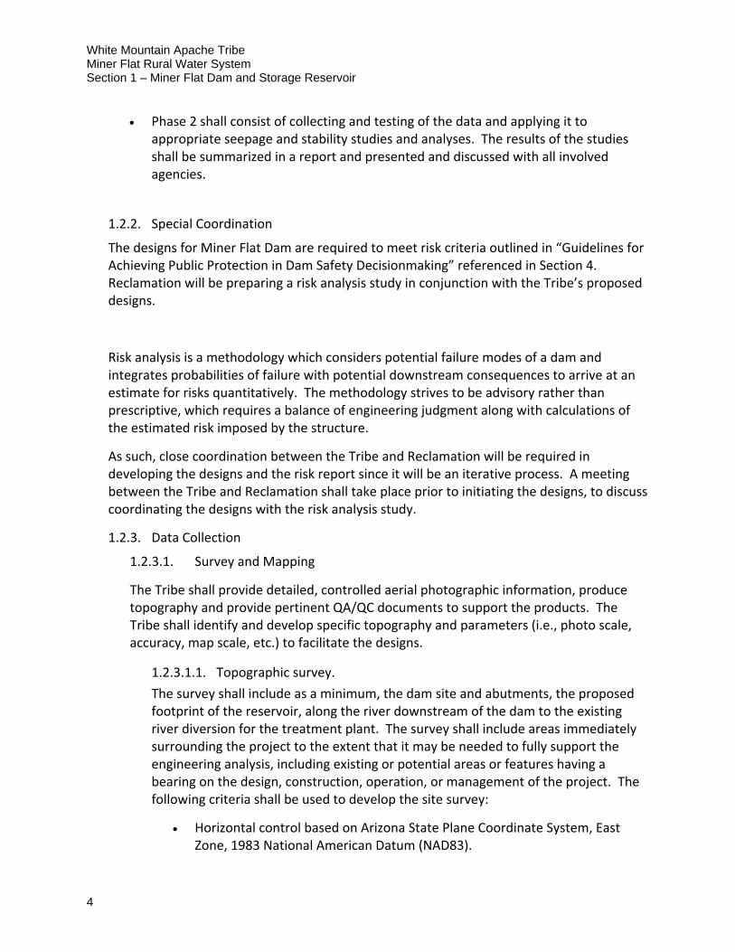
Phase 2 shall consist of collecting and testing of the data and applying it to appropriate seepage and stability studies and analyses. The results of the studies shall be summarized in a report and presented and discussed with all involved agencies.
1.2.2. Special Coordination
The designs for Miner Flat Dam are required to meet risk criteria outlined in “Guidelines for Achieving Public Protection in Dam Safety Decisionmaking” referenced in Section 4. Reclamation will be preparing a risk analysis study in conjunction with the Tribe’s proposed designs.
Risk analysis is a methodology which considers potential failure modes of a dam and integrates probabilities of failure with potential downstream consequences to arrive at an estimate for risks quantitatively. The methodology strives to be advisory rather than prescriptive, which requires a balance of engineering judgment along with calculations of the estimated risk imposed by the structure.
As such, close coordination between the Tribe and Reclamation will be required in developing the designs and the risk report since it will be an iterative process. A meeting between the Tribe and Reclamation shall take place prior to initiating the designs, to discuss coordinating the designs with the risk analysis study.
1.2.3. Data Collection
1.2.3.1. Survey and Mapping
The Tribe shall provide detailed, controlled aerial photographic information, produce topography and provide pertinent QA/QC documents to support the products. The Tribe shall identify and develop specific topography and parameters (i.e., photo scale, accuracy, map scale, etc.) to facilitate the designs.
1.2.3.1.1. Topographic survey.
The survey shall include as a minimum, the dam site and abutments, the proposed footprint of the reservoir, along the river downstream of the dam to the existing river diversion for the treatment plant. The survey shall include areas immediately surrounding the project to the extent that it may be needed to fully support the engineering analysis, including existing or potential areas or features having a bearing on the design, construction, operation, or management of the project. The following criteria shall be used to develop the site survey:
Horizontal control based on Arizona State Plane Coordinate System, East Zone, 1983 National American Datum (NAD83).
White Mountain Apache Tribe Miner Flat Rural Water System
Section 1 – Miner Flat Dam and Storage Reservoir
5
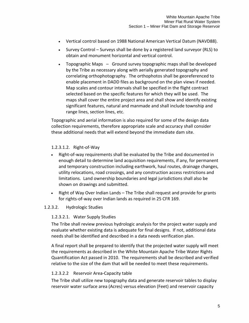
Vertical control based on 1988 National American Vertical Datum (NAVD88).
Survey Control – Surveys shall be done by a registered land surveyor (RLS) to obtain and monument horizontal and vertical control.
Topographic Maps – Ground survey topographic maps shall be developed by the Tribe as necessary along with aerially generated topography and correlating orthophotography. The orthophotos shall be georeferenced to enable placement in DADD files as background on the plan views if needed. Map scales and contour intervals shall be specified in the flight contract selected based on the specific features for which they will be used. The maps shall cover the entire project area and shall show and identify existing significant features, natural and manmade and shall include township and range lines, section lines, etc.
Topographic and aerial information is also required for some of the design data collection requirements, therefore appropriate scale and accuracy shall consider these additional needs that will extend beyond the immediate dam site.
1.2.3.1.2. Right‐of‐Way
Right‐of‐way requirements shall be evaluated by the Tribe and documented in enough detail to determine land acquisition requirements, if any, for permanent and temporary construction including earthwork, haul routes, drainage changes, utility relocations, road crossings, and any construction access restrictions and limitations. Land ownership boundaries and legal jurisdictions shall also be shown on drawings and submitted.
Right of Way Over Indian Lands – The Tribe shall request and provide for grants for rights‐of‐way over Indian lands as required in 25 CFR 169.
1.2.3.2. Hydrologic Studies
1.2.3.2.1. Water Supply Studies
The Tribe shall review previous hydrologic analysis for the project water supply and evaluate whether existing data is adequate for final designs. If not, additional data needs shall be identified and described in a data needs verification plan.
A final report shall be prepared to identify that the projected water supply will meet the requirements as described in the White Mountain Apache Tribe Water Rights Quantification Act passed in 2010. The requirements shall be described and verified relative to the size of the dam that will be needed to meet these requirements.
1.2.3.2.2 Reservoir Area‐Capacity table
The Tribe shall utilize new topography data and generate reservoir tables to display reservoir water surface area (Acres) versus elevation (Feet) and reservoir capacity
White Mountain Apache Tribe Miner Flat Rural Water System Section 1 – Miner Flat Dam and Storage Reservoir
6
(Acre‐Feet) versus elevation (Feet). The tables shall be prepared at 0.1ft. elevation increments and shall extend above the dam crest elevation to account for potential dam overtopping for remote flood events up to the probable maximum flood level.
1.2.3.2.3. Hydrology Studies
All flood loadings for the dam will be prepared by Reclamation and provided to the Tribe to be utilized in the designs. Hydrographs will include paleoflood estimates to produce frequency floods.
Hydrographs will be utilized for developing designs for the dam, spillway, outlet works structures and diversion during construction. Seasonal diversion/construction hydrographs will be developed also to be utilized in evaluating risk during construction.
1.2.3.2.4. Post Dam Construction Impacts
The Tribe shall evaluate hydraulic and sedimentation impacts from the construction of Miners Flat Dam and prepare a report to include the following:
Potential for incision and modification to the river bed‐material gradation in the alluvial river downstream of Miners Flat Dam due to reduction in sediment load and alteration of flood flows.
Potential for altering downstream river habitat and vegetation function due to reduction in sediment load and alteration of stream flows.
Potential for altering stream temperature in downstream river from reservoir releases.
1.2.4. Reservoir Seepage
The Tribe shall review existing reservoir seepage studies contained in the PER and identify required data to be collected to adequately assess long‐term reservoir seepage estimated. The data is also needed to assess left abutment, dam and foundation stability issues. The Tribe shall prepare a final report to describe and estimate seepage conditions anticipated as a result of the proposed reservoir. This report would be the basis of identifying and recommending a plan for grouting of the dam foundation and abutments.
1.2.5. Seismotectonic Studies
The Tribe shall provide preliminary probabilistic seismic loadings for the proposed dam. Seismic loadings shall be determined by completing specific studies, which are subdivided into two main tasks outlined below. The loadings shall be utilized by Reclamation to assess risk for the dam and shall be used for design loadings for the structures. The Tribe shall establish the Design Basis Earthquake (DBE) by coordination with the Reclamation risk analysis studies to ensure the DBE meets the risk criteria.
White Mountain Apache Tribe Miner Flat Rural Water System
Section 1 – Miner Flat Dam and Storage Reservoir
7
Identify and define the characteristics of main potential sources of seismic loadings. Potentially significant sources of seismic loadings within 50 km of the proposed Miner Flat Dam shall be identified. These include loadings generated by mapped active faults, and by seismicity that is unrelated to known or mapped faults. Major mapped faults with evidence of Quaternary (within the last about 1.6 million years activity shall be compiled from readily available information, including published literature, and unpublished technical reports. In particular, publications by the U.S. Geological Survey and Arizona Geological Survey shall be consulted. Preliminary characteristics for significant mapped Quaternary faults will be estimated using available literature. The bases of these estimates and their limitations will be documented, including the need for additional study to refine the estimates. To account for the hazard from earthquakes unrelated to known or mapped faults, a background seismicity source zone based on historic seismicity and/or GPS‐measured geodetic deformation shall be defined. In addition, the potential for seismic sources related to volcanic activity shall be considered.
Complete a probabilistic seismic hazard analysis ‐ All identified potential seismic sources shall be incorporated into a probabilistic seismic hazard analysis (PSHA) for Miner Flat Dam. In order to use the sources in the PSHA, activity rates must be estimated for each identified potential seismic source. For fault sources, additional characteristics, such as fault dip, rupture length, and earthquake recurrence model, will need to be determined. Regional deformation rates estimated using GPS (global positioning system) measurements shall be considered, if available, and compared to deformation rates estimated from geologic data. The PSHA shall be completed using current ground‐motion attenuation relationships available, such as those developed as part of the 2008 NGA Project sponsored by the Pacific Earthquake Engineering Research Center (PEER) Lifelines Program (http://peer.berkeley.edu/products/rep_nga_models.html), and appropriate for east‐central Arizona. Weightings for the attenuations shall be developed and justified. Site‐specific shear‐wave data shall be estimated from available geologic or other information. Hazard curves shall be produced that are appropriate for the foundation shear‐wave velocities measured at the site. Hazard curves shall include the total mean hazard, as well as the individual mean hazard curves from all potential fault sources and the background seismicity source zones. Total hazard curves shall include mean and 84th percentile estimates. Hazard curves shall be produced at a range of spectral periods up to 5 seconds, including the critical response periods of the proposed dam and appurtenant structures. A set of uniform hazard spectrum (UHS) shall be produced for return periods of 500, 1,000, 2,500, 5,000, 10,000, 25,000 and 50,000 years. For each return period and spectral period, the seismic hazard shall be disaggregated by magnitude, geographic location, distance, and epsilon value to demonstrate which earthquake scenarios control the hazard. Uncertainty in input parameters shall be treated using a logic‐tree approach and be fully documented.
White Mountain Apache Tribe Miner Flat Rural Water System Section 1 – Miner Flat Dam and Storage Reservoir
8
1.3. Dam Design and Analysis
1.3.1. Dam Design
The concept layout for the RCC dam is shown in the PER. Generally, the dam shall be designed to the 30% milestone level using current practice and the state of the art techniques for RCC. The layout, geometry and configuration of the dam shall be integrated with the dam analysis, foundation analysis, and geologic information available and obtained. The Tribe shall include an evaluation and report for establishing the Inflow Design Flood (IDF) to be used for designing the dam and associated waterways which shall utilize and be coordinated with Reclamations risk analysis methodology and report. Selecting and establishing the IDF will require judgment and the Tribe shall utilize Reclamations Dam Safety Public Protection Guidelines, 2011, noted in Section 4. It is typically desired that the IDF be the lowest level of flood acceptable utilizing this criteria however, higher levels shall be considered if conditions are justified. The IDF shall not be greater than the probable maximum flood (PMF). Key design considerations for designing the dam that shall be included, but not limited to, are: static loading, hydrologic loading, seismic loading, dam and foundation interaction, control of uplift pressure, seepage control thru the dam at lift lines and contraction joints, temperature control and crack considerations and monitoring of the dams performance both long and short term. The Tribes designs, specifications and products shall consider and include:
Draft technical design reports, drawings and specifications to be completed and submitted for review at the 30% milestone.
A seepage analysis to determine the water loads used in the rock stability analysis, to address grouting, seepage and internal erosion associated with buried alluvial channel materials beneath the foundation of the dam, and to consider any associated operation and maintenance issues.
A grouting and drainage gallery integrated into the design of the roller compacted concrete dam. The grouting and drainage gallery shall provide a means for performing curtain grouting of the foundation, control of foundation and internal drainage, and monitoring and inspection access.
Identifying and collecting design data to provide sufficient geologic exploration and investigations to prepare the specifications and define the requirement for foundation grouting and stabilization. This may include, but is not limited to documentation of water testing in boreholes; weathering profiles; spacing, dip and strike of rock jointing; RQD, foundation modulus of dam foundation, etc.
Contraction joints that include seepage control features such as waterstops, membranes, and internal drainage shall be considered. The spacing of contraction joints will depend on the results of temperature studies to determine acceptable or desired joint opening.
White Mountain Apache Tribe Miner Flat Rural Water System
Section 1 – Miner Flat Dam and Storage Reservoir
9
Quantity estimates for all features of the dam and related features to the 30% milestone level.
1.3.2. Dam Analysis
The Tribe shall perform structural analyses to facilitate the design and understanding of the behavior of the dam under static, hydrologic and seismic loadings. Material properties used shall be based on laboratory testing and/or mix design data. The structural analyses of the proposed RCC dam shall include:
Two‐dimensional analyses of the maximum spillway and non‐overflow sections of the dam/foundation/reservoir system and any cofferdams for static and flood loading.
Three‐dimensional analyses of the dam‐foundation –reservoir system for thermal and earthquake loading, including;
o Any potentially movable blocks in the foundation and abutments. These analyses shall be used to finalize the dam geometry, including but not limited to location of contraction joints and grouting details, slope of downstream face of the dam, and dam‐foundation contact details.
A two‐dimensional analysis model can be used to determine the appropriate design downstream slope.
1.3.3. Geology
1.3.3.1. Surface geology
The Tribe shall geologically map the entire dam site at a regional reconnaissance scale and a site geology map to the 30% milestone level. Scale selection depends on size of the engineered structure and the complexity of the geology. Maps of smaller areas may be generated at scales larger than the base map to illustrate critical conditions. Geologic cross sections shall be prepared to transect critical subsurface geology to include;
At minimum, a geologic section cut through the maximum section normal to the dam axis
A geologic section along the dam axis showing both abutments.
Additional cross sections (at least two) shall be developed through the left abutment ridge, normal to the ridge. Vertical exaggeration on sections shall be avoided.
Various rock types shall be delineated and described in accordance with the USBR Engineering Geology Field Manual.
White Mountain Apache Tribe Miner Flat Rural Water System Section 1 – Miner Flat Dam and Storage Reservoir
10
Discontinuities shall be mapped and described to define “joint” sets based on orientation and dip. Continuity and frequency shall be described for each set along with roughness, openness and connectivity.
Surficial deposits including alluvium and colluvium shall be delineated and described using the Unified Soil Classification System. Specific attention shall be paid to the occurrence of the paleo‐alluvium in outcrop. Thicknesses of surficial deposits shall be estimated or excavated to bedrock to define quantity of material in place.
Materials required for construction activities shall be investigated through borrow area investigations and/or commercial sources. The following items list considerations for defining material data:
Information on concrete aggregates.
Data on commercial concrete plants within hauling distances from the site.
Information on sources and character of acceptable road surfacing materials, if required.
References to results of previous tests of materials including service history and photographs of sources.
Report alkali conditions in soil, aggregate and water which might affect the choice of sulfate resisting cement.
Requirements concerning stockpiles and suggested permanent stockpile locations.
Environmental impacts associated with removing or obtaining construction material.
1.3.3.2. Subsurface geology
The Tribe shall thoroughly be familiar with the existing data identified in the PER and other reference documents noted in Section 4. Previous drilling efforts shall be consolidated and plotted on scaled engineering drawings.
The Tribe shall conduct such additional drilling commensurate with the 30% design milestone as necessary to:
Define rock properties required for design and construction.
To develop a working knowledge of high angle fractures and their apertures (aperture being the unfilled or open width of the fracture).
To develop cross cutting relationships and separating cooling joints related to deposition from post depositional fracturing.

White Mountain Apache Tribe Miner Flat Rural Water System
Section 1 – Miner Flat Dam and Storage Reservoir
11
Primary permeability testing of rock cores, both igneous and sedimentary, shall be conducted, along with downhole permeability testing of all rock types. Quantifying the total permeability of in‐situ rock in the foundation and abutments is paramount for defining potential seepage and grouting requirements.
Downhole, oriented video logging shall be conducted to further the fracture network understanding. Specific to the site, both the paleo‐alluvium and overlying basalt shall have isopach maps developed to fully understand the potential variations in unit thicknesses. Additional permeability testing of paleo‐alluvium shall be conducted over a larger area to better define the physical properties of the material.
The Tribe shall conduct a grout‐take test in the paleo‐alluvium, and if possible, sample in‐situ paleo‐alluvium in out‐ crop to determine representative physical properties.
1.3.3.3. Geologic Design Data Report
A Draft Geologic Design Data Report to the 30% design milestone level shall be prepared which summarizes all aspects of investigations and testing. All geologic data shall be included in a draft geologic report to support the design. The report shall be as concise as possible, consistent with the geologic program, which was previously established. Consideration of the following items as a minimum, shall allow for the development of geologic drawings and specification paragraphs:
A description of regional geology.
A description and interpretation of site geology, including physical quality, excavation characteristics and geologic structure of the foundation strata and ground water conditions, existing and potential slide areas, and engineering geologic interpretations, as appropriate.
Geologic logs of all subsurface exploration. All exploratory borehole locations and elevations shall be based on the same survey control system.
A geologic map, plotted on the topographic map of the site, showing surface geology and the location of geologic sections, soil profiles, and all subsurface exploration.
Geologic sections, with soil profiles as required, showing known and interpreted subsurface conditions.
Aerial photographs or mosaics of the dam site and reservoir area, if available. Aerial coverage shall extend beyond the reservoir area to include geologic and terrain features that would influence water‐holding capability of reservoir.
Samples of foundation strata as needed for visual examination or laboratory testing.
White Mountain Apache Tribe Miner Flat Rural Water System Section 1 – Miner Flat Dam and Storage Reservoir
12
A delineation of the lateral extent and thickness of critical, incompetent, or potentially unstable strata.
A determination by limited tests of the significant engineering properties of the soil and rock (including fracture infillings) materials at the site such as excavation characteristics, density, permeability, erodibility, compressive strength, elastic modulus, shear strength, strain characteristics, and consolidation or expansion characteristics, and the effect of structure load, changes in moisture, and fluctuations or permanent rise of ground water on these properties. The description shall also include:
o A description of the depth to and contour of bedrock; thickness of
weathered, altered, or otherwise softened zones; and other structural weaknesses and discontinuities.
o A delineation of structurally weak, pervious, and potentially unstable zones and strata of soft rock and/or soil.
o Geological information pertinent to reservoir water‐holding capability, operation, and use; location and type of mines or mining claims, potential landslides, and major faults.
o A surface and subsurface groundwater evaluation including regional water data from nearby wells and all piezometric and permeability data.
o A construction considerations section outlining excavation, de‐watering, access, slope stability, blasting, temporary excavation restrictions and various construction activities related to geology and material to the 30% design level.
1.3.4. Foundation
1.3.4.1. Data Collection
The Tribe shall review the existing data and develop an exploration program to collect additional data to support the rock excavations and foundation of the dam. The program shall include:
Surface discontinuity mapping,
Comprehensive foundation and abutment seepage and stability studies,
Drainage system requirements,
Downhole discontinuity surveys,
Constant and falling head permeability testing,
Rock sampling for shear testing and rock modulus determination,

White Mountain Apache Tribe Miner Flat Rural Water System
Section 1 – Miner Flat Dam and Storage Reservoir
13
Any other data that the Tribe deems necessary in the design of rock stability features.
Samples of rock shall be sent to a certified lab to have shear testing, rock modulus, and other similar testing that the Tribe requires to complete the rock stability and roller compacted concrete dam design. As much of these activities as possible should be completed at the 30% design level. If data cannot be obtained, assumptions for both rock properties and characteristics should be made to advance the design to the 30% level.
1.3.4.2. Analysis and Design
Once the data is obtained, a rock stabilization design, interaction with the roller compacted concrete dam, and seepage analysis shall be performed.
1.3.4.3. Rock Stabilization
The Tribe shall prepare a three‐dimensional analysis that includes interaction with the roller compacted concrete dam, documenting steps necessary to stabilize the rock abutments and the foundation of the dam to the 30% milestone level.
The stability analysis shall include identification of unstable blocks, potential uplift pressures, and methods to stabilize those blocks which have been created by the rock excavation. Rock stability analyses to the 30% design level shall be performed for static, seismic and hydrologic loading conditions.
1.3.4.3.1. Rock Stabilization Elements
A list of elements which may be used for stabilization might include rock anchors, rock bolts, wire mesh or fabric, shotcrete, strapping, strip drains, and drilled slotted pipe drains.
1.3.4.4. Design and Specifications
Once 30% design of the rock stabilization methods has been completed, the Tribe shall prepare 30% design appraisal level quantities and cost estimates, specification paragraphs and design drawings.
In addition, the Tribe shall prepare foundation rock excavation, including blasting, quantities, specification paragraphs, and design drawings to the 30% design level.
1.3.5. Grouting
Foundation grouting beneath Miner Flat Dam and in both abutments is anticipated. The Tribe shall provide 30% designs for:
Curtain grouting;
Blanket grouting;
White Mountain Apache Tribe Miner Flat Rural Water System Section 1 – Miner Flat Dam and Storage Reservoir
14
Backfill grouting for tunnels, gate chamber, adits, shafts or any other feature that requires backfill grouting;
Pressure grouting for tunnels, gate chamber, adits, shafts or any other feature that requires pressure grouting.
1.3.5.1. Grouting Engineer
The Tribe shall provide a grouting engineer to prepare and oversee grouting operations with a minimum of 10 years of experience in design and construction for grouting dam foundations or other high hazard structures and worked on at least 3 projects of similar scope. The resume of the Grouting Engineer shall be submitted to the Contracting Officer for review and approval.
1.3.5.2. Review Existing Data
The grouting engineer shall review the existing data and assist in the development of an exploration program to collect additional data needed for final designs related to foundation grouting. Additional permeability testing to determine the primary permeability and secondary permeability of the rock mass and updated seepage analyses are believed to be needed to develop 30% designs.
1.3.5.3. Determination of Lateral and Vertical Extents
The grouting engineer shall assist the design team in the determination of the lateral and vertical extents of the foundation grouting program based on the available geologic data, the results of stability analyses, the potential failure modes, the estimated seepage through the foundation, and the long term operation and maintenance (O&M) needs. The Tribe shall consider the estimated seepage through the dam foundation to verify it will meet long term O&M considerations.
1.3.5.4. Design of Grouting Program
The grouting engineer shall design a grouting program to the 30% milestone level that clearly defines the ‘measure of success’ for grouting each stage within a grout hole and for completion of a grout hole pattern. The split spacing method of grout holes (Primary Holes, Secondary Holes, Tertiary Holes, etc.) shall be used to obtain closure of a grout hole pattern during foundation/abutment grouting. Grouting shall not be accomplished by following a set of instructions as this will require continual evaluation and judgment. The grouting program shall allow for flexibility for qualified field staff to change the program as needed based on the results of water tests and grout ‘takes’. The use of the Grout Intensity Number (GIN) Method or similar method is not an acceptable procedure for grouting at Miner Flat Dam. At a minimum, the following additional information shall also be included within the grouting design for each feature at Miner Flat Dam:
White Mountain Apache Tribe Miner Flat Rural Water System
Section 1 – Miner Flat Dam and Storage Reservoir
15
Scheduling, sequencing, and coordination of grouting operations with other project features
Identification of constraints based on geologic conditions at the dam site.
Grout hole location, spacing, direction and depth.
Provisions for adding additional grout holes.
Provisions for ‘stage up’ or ‘stage down’ grouting.
Drilling methods, requirements and equipment.
Grouting equipment and material requirements.
Requirements for standby equipment.
Grout hole stage length.
Water testing requirements and a clear definition on when grouting is required based on the water test results.
Allowable grout injection pressures.
Grout mix and materials – Grouting at Miner Flat Dam shall use the optimum grout mix, which is defined as the grout mix that the rock will readily accept at the allowable injection pressure.
Supervision of work and implementation of field quality control and quality assurance requirements.
Verification requirements.
Record keeping.
Monitoring requirements to safeguard against foundation displacement.
Provisions for addressing communication between adjacent grout holes.
Provisions for sealing leaks.
Communication requirements and equipment needed for construction personnel and QA/QC personnel.
1.3.6. Spillway
The Tribe shall design a spillway to the 30% milestone to enable the safe passage of flood flows past the dam. The spillway shall be designed as a minimum in accordance with Section 4 Codes, Standards and Reference Documents which includes various documents which outline basic spillway design criteria. The spillway shall be designed to:
Accommodate/pass the IDF consistent with Design Standards No. 14 ‐ Appurtenant Structures for Dams, Chapter 2, Hydrologic Considerations.

White Mountain Apache Tribe Miner Flat Rural Water System Section 1 – Miner Flat Dam and Storage Reservoir
16
Address issues/concerns identified through Reclamation’s risk analysis which evaluates failure modes and assesses risk associated with failure modes in order to evaluate acceptable spillway sizes to be considered.
Safely dissipate the energy such as utilizing a stepped spillway chute and stilling basin.
Include structural and hydraulic parameters and loads, including static, dynamic and seismic loadings.
Minimize impacts of spillway discharges on the downstream fishery.
Spillway design and concepts shall consider minimizing future maintenance costs.
1.3.7. Outlet Works
The Tribe shall design an outlet works to the 30% milestone for the dam to meet Reclamation criteria outlined in Section 4 ‐ Codes, Standards and Reference Documents. The outlet works shall be designed:
To meet reservoir evacuation guidelines.
To meet downstream water use requirements by the Tribe.
To enable passage of minimum stream flow requirements.
To accommodate diversion during construction if the outlet works will be utilized to accommodate flows during the construction period.
With a multi‐level intake structure to account for the estimated sediment load and to be capable of regulating temperatures relative to the downstream fishery.
To enable future development of a hydroelectric power plant.
1.3.8. Outlet Works Control House
The Tribe shall design a control house to the 30% milestone for the outlet works control features located on the downstream side of the dam. The control house shall be designed for:
All necessary mechanical and electrical, equipment and features as required by all paragraphs in this statement of work.
Potentially high tailwater elevations and potential dam overtopping conditions.
Access for all potential maintenance operations needed with long term considerations.
Security measures as required by the Tribe, BIA and Reclamation.
1.3.9. Diversion during Construction
White Mountain Apache Tribe Miner Flat Rural Water System
Section 1 – Miner Flat Dam and Storage Reservoir
17
The Tribe shall develop a plan for diverting and controlling the river flows during construction. The design for diversion during the construction period shall be clearly described in the specifications paragraphs to the 30% milestone level and include:
Close coordination with dam design activities.
Flood frequency hydrographs used as the basis of diversion features.
Sizing and sequencing of the upstream and downstream cofferdams and the bypass waterway designs to accommodate the selected floods during the construction period. The schedule and sequencing of the planned construction of the dam shall be integrated into the sizing of the river diversion features.
Address any dewatering and unwatering requirements anticipated.
1.3.10. Electrical
1.3.10.1. Power ‐ The Tribe shall:
Access and coordinate incoming power requirements with the local utility.
Provide analysis and design to the 30% milestone level for the electrical systems including:
480 volts, 3 phase and 208/120 volts, 3 phase power distribution in the new control building, including:
U.S. Department of the Interior standard and utility power metering
o Single line including panels, transformers, and calculated loads
o All panel schedules, wire and cable specifications, conduit specifications, devices and fixtures specifications, and grounding and bonding specifications
1.3.10.2. Lighting and HVAC systems
Lighting and HVAC controls shall be a single system designed to optimize building energy use.
1.3.10.3. Electrical Controls
The Tribe shall design the electrical controls for the outlet gates and valves to the 30% milestone level.
1.3.10.4. SCADA
White Mountain Apache Tribe Miner Flat Rural Water System Section 1 – Miner Flat Dam and Storage Reservoir
18
The Tribe shall design the voice and communications (SCADA) systems to the 30% milestone level based in accordance with the desires or the Tribe regarding locations, monitoring capabilities, remote control and viewing capabilities, etc.
1.3.10.5. Security Systems
The Tribe shall design building security system to the 30% milestone level.
1.3.10.6. Emergency Power
The Tribe shall design the emergency (backup system) power to operate gates, valves and other features requiring power in the outlet works control house as well as any other features at the dam which require power upon loss of normal power sources to the 30% milestone level.
1.3.11. Mechanical ‐ Outlet Works
The following design criteria and performance objectives for the steel pipe, gates, and/or valves for the river outlet works shall be made part of the 30% design criteria and performance objectives:
1.3.11.1. Steel Pipe
Steel pipe shall be provided from the multi‐level intake structure to the control house and shall:
Be designed in accordance with AWWA Design Manual M‐11 and the ASCE Manuals and Reports on Engineering Practice No. 79.
Be fabricated in accordance with guidelines found in AWWA Standard C200.
Have a maximum allowable design stress of 18,000 pounds per square inch. Pipe wall thicknesses are determined considering the following:
o Internal pressure
o Amstutz or Jacobsen criteria for external pressure (for the encased section of the pipe).
Be designed for handling (Minimum plate thicknesses for handling are in accordance with AWWA recommendations. This minimum thickness needed for handling is the lesser of d/288 for pipe sizes up to 54‐inch and (d+20)/400 for pipe sizes greater than 54. The “d” is diameter in inches.)
In all cases, not have a wall thickness less than one‐fourth inch.
Be sized such that the maximum velocity through the steel pipe is not more than 25 feet per second when the outlet is delivering the maximum designed flow rate during normal operation.
White Mountain Apache Tribe Miner Flat Rural Water System
Section 1 – Miner Flat Dam and Storage Reservoir
19
Provide for an air inlet immediately downstream of the emergency closing gate. This vent is to be sized to prevent a pipe collapse in the event that the emergency gate is suddenly closed.
1.3.11.2. Gates in the Tower
The gates in the multi‐level intake tower can be commercially available gates. These can be designed by the gate supplier.
1.3.11.3. Gate Actuators
The actuator for each gate shall be:
Designed to accommodate the maximum water surface.
Either hydraulic (oil) or electric‐motor operated.
Connected to the gates with a steel gate stem that extends from the actuators to the gate.
1.3.11.4. Emergency Closing Gate
In the event that the control valve cannot be closed or there is a pipe break downstream of the dam, an emergency gate shall be located at the inlet to the steel pipe. This emergency closing gate shall:
Be designed to be closed under unbalanced and uncontrolled flow conditions.
Be designed to close without power (i.e. closed only by the weight of the gate (gravity).
Be either a wheel mounted gate or a wheel mounted bulkhead gate, normally raised and lowered with a motor operated hoist (cable).
1.3.11.5. Outlet Works Control Valve
A control valve/gate shall be provided for control of the outlet works. That valve/gate shall be:
Bolted (flanged connection) to the end of the steel pipe at the control house location.
Suitable for free discharge control.
Either a commercially available fixed‐cone valve or a jet‐flow gate.
Sized to accommodate:
White Mountain Apache Tribe Miner Flat Rural Water System Section 1 – Miner Flat Dam and Storage Reservoir
20
o The range of the designed flow rates (minimum to maximum) at the head (pressure) provided when the reservoir is at the normal operating water surface or other water surface elevations as determined by the future operators of the dam.
o Other criteria such as reservoir evacuation requirements.
Controlled by either a hydraulic (oil) or electric motor operated actuator
designed to accommodate the maximum water surface.
1.3.11.6. Bulkhead, Guides and Intake Trashracks
Bulkhead, guides and intake trashracks shall be designed:
In accordance with AISC ‐ Manual of Steel Construction Allowable Strength Design, Thirteenth Edition. These items are to be fabricated in accordance with ASTM A36.
Such that the maximum water velocity approaching the trashracks is not more than 2 feet per second when the outlet is delivering the maximum designed flowrate over the normal operating range.
For 2/3 of maximum head or 20‐foot differential, whichever is less.
Clear opening between trashrack bars as required to protect the downstream equipment. Normal clear opening ranges between 2 to 4 inches.
1.3.11.7. Engine Generator (E‐G) Set
The Engine Generator Set shall be either LPG or diesel, and shall:
Be designed in accordance with NFPA, NEMA, ASME, state and local codes.
Be sized based on the type of equipment and loads that the unit will have to start up at the same time and carry.
Be de‐rated for altitude and maximum temperature and designed for startup loads.
Contain secondary containment and a leak detection system (if diesel fueled)
Be sized (fuel tank) to provide a minimum of 36‐hours of continuous operation.
Be designed with an above‐ground fuel tank.
Have a tank that has an ASME code official stamp if LPG fueled.
Design the intake and exhaust vents to not exceed the following air velocities based on the E‐G set cooling requirements (if installed indoors). Position vents to create a cross‐flow across the generator as follows:
White Mountain Apache Tribe Miner Flat Rural Water System
Section 1 – Miner Flat Dam and Storage Reservoir
21
o Outlet Vent – 550 ft/minute maximum air velocity
o Inlet Vent – 375 ft/minute maximum air velocity
Provide floor vents (for indoor LPG units) per NFPA code requirements.
1.3.11.8. HVAC System
The Tribe shall design the HVAC system for the control house in accordance with ASHRAE, state and local codes.
1.3.11.9. Sump Pump(s)
Sump pumps shall meet the requirements for maximum and minimum head and flow rates.
1.3.12. Mechanical – Spillway
If mechanical equipment is proposed for spillway gates or operations, it shall comply with Section 4 ‐ Codes, Standards and Reference Documents.
1.3.13. Miscellaneous Metalwork
The Tribe is responsible for the design of miscellaneous metalwork items to the 30% milestone level, which includes, but is not limited to, the following:
Pipe guardrails and handrails;
Stairways;
Ladders;
Frames and gratings; and
Roof hatches, doors and door frames.
1.3.13.1. Ferrous Metalwork
All ferrous metalwork shall be galvanized after fabrication.
1.3.13.2. AISC Steel Code Manual
The Tribe shall design the miscellaneous metalwork in accordance with the applicable provisions of AISC Steel Code Manual, AWS D1.1 Structural Welding Code, and Code of Federal Regulations (CFR) 29, Part 1910 ‐ Occupational Safety and Health Standards.
1.3.13.3. Stairways, Frames and Gratings
Minimum design live load for stairways, frames and gratings shall be 100 pounds‐per‐square foot.
White Mountain Apache Tribe Miner Flat Rural Water System Section 1 – Miner Flat Dam and Storage Reservoir
22
1.3.14. Instrumentation
The Tribe shall design the instrumentation systems to the 30% milestone level to monitor the following items for the dam as a minimum:
Temperature and pressure monitoring devices embedded into the lift lines.
Drainage and seepage flow data (flow shall be visible and sedimentation shall be designed to be collected at the measurement device).
Uplift pressure measurement at the foundation of the dam. At least one device shall be installed for each vertical block of concrete of horizontal section with unusual foundation conditions.
Deformation (horizontal and vertical) ‐ At least one device shall be installed for each vertical block of concrete of horizontal section with unusual foundation conditions. Vertical deformation devices may be located at the top of the dam or at the foundation. Horizontal deformation must be configured to allow rotation or tilt to be detected.
The following are minimum requirements and types of instrumentation requirements anticipated for the dam:
Instrumentation Plan and Profile
Instrumentation Sections
Piezometer Installation Details
Inclinometer Installation Details
Tiltmeter Installation Details
Extensometer Installation Details
Thermistor Installation Details
Thermistor Installation and Cable Routing Details
Weir and Surface Monument Details
Drainage and Seepage Location Collection
Water Level Float System Installations
Collimation and Instrument Pier Location and Installation
1.3.15. Access Roads
The Tribe is responsible for the 30% milestone design of :
White Mountain Apache Tribe Miner Flat Rural Water System
Section 1 – Miner Flat Dam and Storage Reservoir
23
Permanent access road to the crest elevation of Miner Flat Dam, a permanent access road to the downstream side of the dam, and any other permanent access roads based on project needs. All permanent roads shall be designed to applicable design standards.
Permanent access to a control house on the downstream side of Miner Flat Dam is needed to provide for maintenance and allow for operations of the facilities in the control house. The Tribe may provide access to the control house by whatever means is most practical and economical.
Design of temporary access roads required for construction purposes is typically not anticipated to be designed by Tribe unless specific conditions dictate a need. Commensurate with geotechnical findings, the Tribe shall outline access and excavation restrictions deemed necessary to support dam and foundation stability designs. The Tribe shall prepare designs in compliance with references noted in Section 4.
1.3.16. Hydroelectric Powerplant Evaluation
The Tribe shall evaluate the potential for constructing a hydroelectric powerplant at Miner Flat Dam. The evaluation shall utilize the water supply study as previously noted and the planned operations for the project regarding releases and shall estimate the size of powerplant that is considered justifiable. The Tribe shall prepare a cost estimate for the construction of the powerplant to include costs for excavation. The powerplant shall be displayed on an appraisal level drawing. A cost estimate for the powerplant itself may utilize a similar size powerplant Consideration should also be made relative to the design of the dam and spillway considering the potential to overtop the dam for remote flood events.
Economics of power generation shall be described in an evaluation report to clearly identify whether a hydroelectric powerplant is a practical and economic feature to include in this project.
1.4. Dam Specifications Paragraphs
A Specification Outline shall be prepared in MicroSoft Word (MS Word), following Construction Specifications Institute (CSI) MasterFormat, SectionFormat, and PageFormat; and as directed below:
1.4.1. Master Format
The Tribe shall follow CSI MasterFormat, 2004 Edition, or newer, for Section numbering .
1.4.2. Section Format
The Tribe shall prepare Sections to follow CSI Section Format, 2007 Edition or newer as follows:

White Mountain Apache Tribe Miner Flat Rural Water System Section 1 – Miner Flat Dam and Storage Reservoir
24
1.5. Design Drawings
1.5.1. General
All specifications drawings shall be furnished by the Tribe with an industry standard title block. The drawings shall be D‐size prints as defined in American Society of Mechanical Engineers’ (ASME) Y14.1. All AutoCAD drawings shall be formatted in accordance with U.S. National CAD Standard (NCS) Version 4.
1.5.2. AutoCAD
All drawings shall be prepared using AutoCAD version 2008 or newer.
1.6. Construction Cost Estimates
The Tribe shall prepare a construction cost estimate at the 30% design milestone.
The cost estimate shall include the following (as is applicable to the level of estimate):
Concise documentation of o Applicable pay items
o Quantities
o Unit pricing or detailed pricing (as applicable to the level of cost estimate)
o Allowances (i.e., Mobilization, Design Contingencies, Allowance for Procurement Strategies, and Construction Contingencies) (if applicable to that level of cost estimate)
The cost estimate shall be prepared based upon the following:
1.6.1. 30% Design Level Cost Estimate
The 30% Design level cost estimate shall be used to help define major design and construction features that represent significant cost drivers for the project that will be included or excluded from the final design. The Tribe shall provide details and supporting information as necessary for evaluation and understanding of all lump sum items, as well as other key information that may provide understanding for the unit prices and/or pricing for the identified major items of work (i.e. haul distances, common or rock excavation, borrow or commercial materials sources, access considerations, etc.).
1.6.1.1. Heavy Civil Construction Projects
Contingencies for projects involving typical heavy civil construction projects at the 30% Design cost estimate level may range (but shall be evaluated and adjusted accordingly based on unique circumstances) as follows:
5% to 15% Design Contingencies

White Mountain Apache Tribe Miner Flat Rural Water System
Section 1 – Miner Flat Dam and Storage Reservoir
25
20% to 25% Construction Contingencies
Determine appropriate contingency percentages by evaluating all relevant data with professional judgment
1.7. Construction Schedule
1.7.1. Summary Level
A construction schedule shall be developed by the Tribe for all major construction components required to complete the dam and all the features. The level of detail of the construction schedule shall be as needed to estimate an overall project duration. Describe basis and apply appropriate calendars to the tasks that include non‐work days such as weekends, holidays, and weather/rain.
1.7.2. Software
The construction schedule shall be prepared using Oracle Primavera P3 or an equal software. One CD copy of the electronic schedule file shall be submitted to the Contracting Officer, along with color prints of the schedule. The CD shall be clearly labeled with complete job submittal information. Submit three each, 8‐1/2 inch by 11 inch color copies of a GANT type schedule.
1.8. Constructability Report
A Constructability Report shall be prepared. It shall provide the following critical information in planning the construction phase of the project:
Environmental considerations/requirements that will affect construction and how the design accommodates these requirements;
Discussion of construction methods, including but not limited to diversion of river and cofferdam requirements, placement of concrete, concrete temperature control, rock bolt placement and other slope stabilization methods;
Discussion of physical limitations of the construction sites;
Allowable and/or recommended in‐river work periods;
Temporary site bypass (detour) requirements for roads access roads, if any;
Discussion of potential time constraints (duration, start or finish of project or certain features);
A preliminary construction schedule based on relative time frames (i.e., no dates);
Permits that will likely be required for construction.


White Mountain Apache Tribe Miner Flat Rural Water System
Section 2 – Miner Flat Water Treatment Plant and Diversion
27
2. Miner Flat Water Treatment Plant and Diversion Structure
The following table of deliverables lists the products that the Tribe shall prepare which is described within this section.
Number Description of Deliverable
1 Topographic Maps
2 Right of Way Information
3 Hydrology Report
4 Technical Memorandum – Water Demand
5 Water Quality Database
6 Technical Memorandum – Water Quality
7 Summary of Results – Pilot Study
8 Water Treatment Report
9 Feasibility Design Report
10 30% Design Drawings
11 Specifications Outline
12 Constructability Report
13 Construction Cost Estimate – 30% Design
2.1. Pre‐Design Data Studies and Data Collection
2.1.1. General
The Water Treatment Plant (WTP) design shall include a comprehensive Feasibility Design Report (FDR) documenting the analysis and designs through the 30% stage. This report shall present the features of construction alternatives within the framework of the Miner Flat Dam Project with sufficient detail to support selection of a project configuration which shall be submitted for approval for design and construction. All items that are major cost drivers shall be evaluated and identified in the report. In addition, identification of all major features and considerations that shall be required for the project along with preliminary drawings for the major features shall be included in the FDR. For purposes of this study/report, major features shall be defined as those that are consistently 2 percent or more of construction costs. To the degree it is practical, minor items may be quantified and calculated and individually listed.
Within the constraints of the lands identified as project lands, alternative layouts and designs shall be provided to determine a preferred design that meets all requirements in
White Mountain Apache Tribe Miner Flat Rural Water System Section 2 – Miner Flat Water Treatment Plant and Diversion
28
the most economical and acceptable manner, including the location and manner of diversion from the White River.
2.1.2. Surveying and Mapping
The Tribe shall provide detailed, controlled aerial photographic information and topography. The Tribe shall be required to identify and develop specific topography and data to facilitate the designs for each specific feature. Mapping shall cover the project area, and the area immediately surrounding the project to the extent that it may be needed to fully evaluate the engineering analysis, including existing or potential areas or features having a bearing on the design, construction, operation, or management of the project. The following data shall be collected and shown on mapping in support of the FDR:
Survey Control – Surveys shall be done by a registered land surveyor (RLS) to obtain and monument horizontal and vertical control. Horizontal Control shall be based on the Arizona State Plane Coordinate System, East Zone, 1983 National American Datum (NAD83). Vertical control shall be based on the 1998 National American Vertical Datum (NAVD88)
Topographic Maps – Topographic maps shall be developed at a scale of 1”= 100’ with contour intervals of 2 foot with the underlying aerial photos on the plan views. The maps shall cover the entire project area and shall show and identify existing significant features, natural and manmade and shall include township and range lines, section lines, etc.
Right‐of‐Way Information – Right‐of‐way requirements shall be evaluated and documented in enough detail to determine land acquisition requirements, if any, for permanent and temporary construction including earthwork, haul routes, drainage changes, utility relocations, road crossings, and any construction access restrictions and limitations. Land ownership boundaries and legal jurisdictions shall also be shown.
Right of Way Over Indian Lands – The Tribe shall request and provide for grants for rights‐of‐way over Indian lands as required in 25 CFR 169.
2.1.3. Geotechnical Investigations
Geotechnical investigations for this project shall explore, analyze and document subsurface conditions at the water treatment plant and diversion site, raw water pumping station and finished water storage reservoir to provide conclusions and recommendations for the design and construction of the project. The resulting geotechnical report shall include soil conditions, including type and permeability, sufficient to establish foundation conditions and determine bearing capacities. Specifically, the investigations shall:
White Mountain Apache Tribe Miner Flat Rural Water System
Section 2 – Miner Flat Water Treatment Plant and Diversion Structure
29
Identify seasonal Groundwater elevations (wet and dry periods);
Research historical data relevant to the site;
Identify location and type of rock and soil identified through site borings and/or test pits;
Estimate rock elevations throughout the site;
Make recommendations for excavation and trenching;
Make recommendations for appropriate foundation types for new structures;
Present design criteria for the recommended foundation types;
Identify construction considerations and potential construction problems, if any;
Determine suitability of on‐site excavation to be used as fill and pipe bedding material.
Determination of soil resistivity for pipelines may be required for corrosion considerations for buried metallic water pipe.
2.1.4. Hydrology
A hydrology report shall be prepared and shall include information on river flows, cross‐drainage flows and corresponding water surface elevations as necessary for locating temporary and permanent facilities on or near the river. The report shall also discuss sediment transport, channel degradation or aggradation, scour, bank stability, overall river stability, and potential for sediment intake into the proposed diversion dam, raw water pump station, raw water pipelines and water treatment plant. The report shall also evaluate runoff from any watershed upslope of the project that may impact project facilities, including design storm inflows and associated scour depths.
2.1.5. Water Demand
The Tribe shall review water demand assumptions and data provided in Chapter 3, Domestic Project Formulation, of the Project Extension Report, and modify if necessary to reflect currently available data.
2.1.6. Existing Water Quality
The Tribe shall analyze all existing water quality data and execute a site‐specific data collection plan for source water quality. Field tests and laboratory tests shall be conducted as necessary to determine a proposed treatment process.
2.1.6.1. Surface Water Sources ‐ The Tribe shall:
Obtain and review existing record of raw and treated water quality information for the existing White River Surface Water Treatment Facility (WRSWTF).
Review treatment practices and operating parameters for the WRSWTF.
White Mountain Apache Tribe Miner Flat Rural Water System Section 2 – Miner Flat Water Treatment Plant and Diversion
30
Analyze data collected from source water from reservoirs similar to the water quality anticipated from the waters impounded at the proposed Miner Flat Dam. Analysis shall include the pH, temperature, major ions, contaminants of concern, and other constituents that may affect the treatment process.
2.1.6.2 Water Quality Information Database
The Tribe shall compile, analyze and summarize the information gathered in sub‐task 2.1.6.1 into a water quality database.
2.2. Water Treatment
2.2.1. General
The Tribe shall evaluate specific treatment objectives for expected water quality constituents, based on:
Compliance with federal, and Tribal regulations, and
Other treatment objectives (i.e. water quality goals) that are not based upon specific legal limits.
2.2.2. Surface Water Quality Regulations
Generally, the Tribe should:
Review current and anticipated water quality regulations that affect surface water supplies
Review and summarize the outcome of the regulatory negotiation process to develop the D/DBP Rule and the LT2ESWTR
Review and summarize the advantages and disadvantages of the use of free chlorine as a disinfectant to an alternative and appropriate disinfection method, such as use of chloramine, UV, etc.
Summarize the applicable regulations for the Tribes’ surface water supplies and establish water quality standards from a regulatory perspective
2.2.3. Water Quality Goals
Generally, the Tribe shall:
Obtain and review information on the Tribe’s existing water quality goals
Using the water quality database prepared in Task 2.1.6.2, perform a comparative analysis of the existing water quality with the existing water quality goals
White Mountain Apache Tribe Miner Flat Rural Water System
Section 2 – Miner Flat Water Treatment Plant and Diversion Structure
31
Identify shortcomings and exceedances of existing water quality with respect to the
water quality goals. These identified shortcomings and exceedances shall provide one of the bases for developing alternatives for operation and maintenance of the entire water system
Based upon the evaluations in tasks 2.2.2 and comparisons with the water quality goals, develop future water quality goals for the overall Tribal water supply system
2.2.4. Technical Memorandum
The Tribe shall prepare a technical memorandum for inclusion in the FDR summarizing the findings associated with the existing water quality, consistent with the water quality goals and the applicable water quality regulations.
2.3. Alternative Analyses and Pilot Studies
The Tribe shall consider and analyze reasonable alternatives for water treatment based upon water quality studies conducted under section 2.2. These studies should include:
Research, study, analyze and recommend conventional and "state‐of‐the‐art" technologies and processes for each element of the Project
Include analysis of construction cost and operation, maintenance and replacement costs in the recommendation of alternatives
Develop a pilot testing program
Design and build a pilot testing facility or "pilot plant" suitable for field testing of the recommended filtration/treatment technologies and processes
Perform laboratory and/or field pilot testing of different treatment options to select the appropriate process components to be designed. Additionally, laboratory and/or field pilot testing of the major treatment components shall be performed to collect data for key design and operational parameters
Present a summary of test data and conclusions, and identify future testing needs for final design. The need for test data and the particular treatment operations to be tested depend on the treatment technology, treatment objectives, and other project‐specific factors
Provide key design and operational parameters for the water treatment process and describe their development for each component of the treatment process
2.4. WTP Site Investigation/Evaluation
White Mountain Apache Tribe Miner Flat Rural Water System Section 2 – Miner Flat Water Treatment Plant and Diversion
32
Based upon preliminary treatment concepts and requirements, the Tribe shall compute space (land) requirements that would be required for the treatment plant and appurtenant facilities. Accordingly, the Tribe shall analyze, screen and rank the candidate WTP sites. The matrix analysis shall consider the following factors:
Land availability
Right‐of‐Way issues
Impact on surrounding residents including aesthetics and noise
Access/egress
Proximity to source water
Proximity to distribution system
2.5. Water Treatment Report
The Tribe shall prepare a report for inclusion in the FDR summarizing the information developed in sections 2.3 and 2.4 with appropriate recommendations and conclusions.
2.6. Water Treatment Plant and Appurtenant Facilities Design
The Tribe shall prepare and submit a 30% design submittal package, including design drawings, specifications and construction cost estimate. The Tribe shall investigate, analyze and establish the design parameters, design criteria and concepts necessary for preparation of detailed plans and specifications. The designs shall consider plant‐wise flow rates (considering gradual increase overtime), chemical demands, equipment and operational requirements, process systems layouts, control strategies, and process reliability and redundancy. The following define the requirements under the 30% design submittal:
2.6.1. Treatment Facility Design
Based upon pilot studies, the Tribe shall prepare 30% level designs for the water treatment system. The designs should be supported by:
Flow diagram. A flow schematic that depicts influent, effluent, and all internal flow paths through the treatment plant; corresponding flow quantities shall be shown either on the diagram or separately in a table
Mass balance diagram. A flow schematic that depicts the mass flow rate for constituents of concern and creates a balance between influent and effluent mass flow rates across each treatment operation and the overall treatment process
Hydraulic profile. A diagram that depicts water elevation head through each component of the treatment process
White Mountain Apache Tribe Miner Flat Rural Water System
Section 2 – Miner Flat Water Treatment Plant and Diversion Structure
33
Process and instrumentation diagram ‐ A flow schematic that depicts process and instrumentation components including pipes, valves, pumps, tanks, treatment equipment, sensors, and instrumentation
Power requirements. Estimates of annual power consumption
Projected plant performance ‐ An overall plant performance summary citing the expected treated water quality compared to treatment goals or standards, projected plant capacity, and how variations in water quality and quantity shall be managed
Integration with other project features. A description of the role and relationship of the treatment plant with respect to other project features, including the physical connection or interface and any treatment operation constraints imposed by other project features (flows, pressures, contaminant concentrations, etc.)
2.6.2. Treatment Operation Design
The overall treatment process/design shall be broken down into the major treatment operations, which consist of individual subsystems to accomplish a discrete step of treatment (e.g., coagulation, filtration, disinfection). The 30% designs shall reflect:
Treatment efficacy ‐ The expected efficacy of the treatment operation as compared to the treatment standard or goal, and the ability of the designed subsystem to accommodate expected variations in water quality and quantity
Design details ‐ Details that contain sufficient detail to develop itemized quantity lists for the required equipment, materials, and installation
Treatment chemicals ‐ Treatment operations that require chemical addition should describe the type of chemical, transportation and delivery to the treatment plant, storage, injection equipment, mixing requirements, and concentration and frequency of chemical dose
Identification of construction materials. The selection of materials of construction based upon the evaluation of corrosion and chemical/material compatibility issues
Operation and maintenance issues ‐ Expected run time between maintenance activities, cleaning/backwashing intervals and durations, supervisory control and data acquisition (SCADA), sampling and analysis, expected replacement intervals for major components, etc.
White Mountain Apache Tribe Miner Flat Rural Water System Section 2 – Miner Flat Water Treatment Plant and Diversion
34
Proprietary technology or equipment ‐ Treatment operations or portions thereof that contain proprietary components should be identified as a potential sole‐source acquisition
Packaged treatment systems ‐ Pre‐engineered, prefabricated treatment systems having standard or guaranteed performance specifications may be appropriate for some treatment operations
Equipment redundancy ‐ Most major treatment operations are designed and installed as part of identical and parallel treatment trains to manage flow variations and to provide additional capacity when a treatment train is not operational due to mechanical failure or maintenance activities
Disposition of waste streams ‐ The quantity and composition of the waste, additional required treatment and disposal steps, and any regulatory issues that may apply
Considerations for final design ‐ Description of additional data needs studies, regulatory permits, and treatment issues that shall be addressed in final design
2.6.3. Raw Water Diversion/Delivery Design
The 30% Design of the diversion structure and components to deliver the diverted water to the treatment plant shall include:
2.6.3.1. River Diversion Structure (Dam)
The Tribe shall provide design details as follows:
River cross section, including excavation limits
Foundation treatment
Abutment treatments
Dam type/material
Dam geometry (height/width/depth)
Dam abutment design details
Scour protection/control
Seepage control measures
River diversion during construction
River channel stability requirements
Fish passage requirements

White Mountain Apache Tribe Miner Flat Rural Water System
Section 2 – Miner Flat Water Treatment Plant and Diversion Structure
35
2.6.3.2. Inlet Structure
The Tribe shall provide design details as follows:
Debris exclusion features, sediment exclusion measures and ice concerns
Fish Exclusion details
Trash Rack details
Gates and/or valves
Structural requirements
2.6.3.3. Pumping Plant
Pumps should be modeled based on actual operating curves. The pump station shall be designed to effectively accommodate the anticipated gradual increase over time of the demand. Tribe should identify if commercial package pumping plants are available or if a site built unit is required. Pump station design/acquisition shall consider and address:
Foundation conditions
Excavation details ‐ General layout of the site excavation with sections and details
Concrete slab/floor requirements
Power Accessibility
Backup/Emergency power
Hydraulic Profile ‐ Provide a clear description of the operating conditions at present and future flow conditions that include the extremes of maximum and minimum flows
Pumping Plant general arrangement ‐ General arrangement of the building showing the layout of plant equipment, means of egress, rooms, access hatches/doors, etc. Drawings should show a series of plans with numerous sections and details that are necessary to convey the general layout of the facility
Pump configuration ‐ Number and size of pumps to most effectively meet low and peak demands (current and future)
Pump type and associated efficiencies
Redundancy
Housing/structural requirements ‐ Structural design drawings showing plans, sections, and details of the various structural components, including:
White Mountain Apache Tribe Miner Flat Rural Water System Section 2 – Miner Flat Water Treatment Plant and Diversion
36
Security
Remote operability
Road Access
Corrosion
Valving
2.6.3.4. Raw Water Pipe Design
Pipeline design shall be according to industry standards as listed in Section 4. Designs shall address or include:
Hydraulic properties by reaches of proposed features (including hydraulic grade line, pipe dimensions, and pressure class)
The effect of hydraulic transients on the system. The Tribe shall modify pipe
types, restraints, or add surge suppressors and valve and pump controls as needed to accommodate or mitigate the effects of hydraulic transients
Allowable pipe type – Describe which pipe type alternatives are suitable and
design criteria for each pipe type, allowable joint types, and bedding requirements. Evaluate comparative values/costs of each pipe type considered
Typical Pipe Trench Section – Determine typical trench section for each proposed
pipe option. The typical pipe section would include minimum earth cover, compaction requirements, frost depth, etc.
Crossings of Roads, Railroads, Canals, Rivers, Utilities, etc. – State requirements
for each type of crossing, including allowable pipe type, casing requirements, excavation and backfill requirements, clearance requirements, and burial depth
Valve locations and details, cleanouts, air vents, etc. Flow Measurement ‐ Describe where flow measurement is required, type of
flow measurement required, and how the operators acquire flow rate and total flow (locally or by transmission to a remote location). Selection considerations may include site‐specific factors, operational requirements, accuracy requirements, cost, head loss, ability to pass sediment and debris, maintenance requirements, device standardization, field verification, and vandalism potential
White Mountain Apache Tribe Miner Flat Rural Water System
Section 2 – Miner Flat Water Treatment Plant and Diversion Structure
37
Design should also consider installation requirements such as length of upstream straight pipe, straightening vanes, and ensuring a full pipe at the flow meter location
Corrosion Protection Requirements – Provide design details for corrosion
protection/monitoring, lining requirements, and coating requirements
2.6.3.5. Electrical Design
Any power requirements for operation of the pipeline, pumping plant, flow meters, SCADA system, valve operation, corrosion protection etc should be included. The availability of electric power, power rates, and power requirements of the project should be researched and discussed based on the pumping requirements and pump station details documented in the FDR.
2.6.4. Clearwell (Storage) Reservoir Design
Based upon demand and other factors such as planned and unplanned treatment plant outages, the Tribe shall provide design details of the clearwell reservoir. The design shall include:
Volume requirements
Configuration
Baffling/Mixing facilities
CT requirements
Inlet/outlet details
Materials of construction
2.6.5. Feasibility Design Report (FDR)
All of the foregoing information shall be compiled and incorporated into a comprehensive, bound draft report with conclusions derived as a result of this feasibility level study and shall become the basis of the final designs. Each discreet activity within this scope of work shall be included in the report. The report shall include a title page, table of contents, executive summary and appendices with supporting documentation associated with the study activities. The draft report shall be submitted for review and comment. If determined advantageous, the Tribe shall make a presentation outlining the key aspects.
The Tribe shall record all comments received. Each comment shall be addressed. A final report shall be prepared pursuant to discussions, meetings and presentations during the draft review and distributed for final review. Additional comments if any shall be
White Mountain Apache Tribe Miner Flat Rural Water System Section 2 – Miner Flat Water Treatment Plant and Diversion
38
incorporated as appropriate into the final printed report. The report shall be printed, bound and distributed.
2.6.6. 30% Design Drawings
Drawings for individual components of the project, including the diversion structure, intake structure, raw water pumping station, raw water pipeline, water treatment plant and clearwell shall be prepared sufficient to identify major cost items. The documents shall include partial sets of the following discipline drawings:
General
Civil
Process/Mechanical
Structural
Architectural
Instrumentation and Control
Electrical
2.6.7. Specifications Outline
The Tribe shall prepare and submit a specifications outline for each major project component using CSI MasterFormat 2004 Edition.
2.6.8. Constructability Report
A Constructability Report shall be prepared. It shall provide the following critical information in planning the construction phase of the project:
Environmental considerations/requirements that will affect construction and how the design accommodates these requirements;
Discussion of construction methods, including diversion of river and cofferdam requirements;
Discussion of physical limitations of the construction sites;
Allowable and/or recommended in‐river work periods;
Temporary site bypass (detour) requirements for roads access roads, if any;
Discussion of potential time constraints (duration, start or finish of project or certain features);
A preliminary construction schedule based on relative time frames (i.e., no dates);
Permits that will likely be required for construction.
White Mountain Apache Tribe Miner Flat Rural Water System
Section 2 – Miner Flat Water Treatment Plant and Diversion Structure
39
2.6.9. 30% Construction Cost Estimate
The preliminary (30%) design shall be prepared in sufficient detail to ensure that all items that significantly affect the cost of construction are accounted for in the field cost estimate. Designs shall be completed in enough detail so as to limit the allowance of unlisted items and contingencies as described below. The cost estimates shall include the following (as is applicable to this level of estimate):
2.6.9.1. Pay Items
Pay items for the construction of new features of work include both major and minor items. Major items are those that are consistently 2 percent or more of construction costs. Minor items are less than 2 percent of construction costs. All major cost items shall be quantified and estimated individually. Where practical, the quantity and cost for minor items shall be calculated and individually listed in the cost estimate as well.
2.6.9.2. Unit Costs
Market research shall be conducted and existing historic cost data shall be referenced in determining appropriate unit costs for each of the pay items.
2.6.9.3. Field Cost Estimates
Field costs shall be estimated based on computed quantities and unit costs. In addition the field costs shall assume the following:
Allowance for Design Contingencies (Unlisted Items) ‐ This line item in the field cost estimate shall be included to approximate the costs of unlisted minor and undefined items. This percentage shall not exceed 10 percent
Construction Contingencies ‐ Field cost estimates include a percentage allowance for contingencies as a separate line item to cover minor differences in actual quantities and the quantities estimated during the feasibility design phase, unforeseen difficulties at the site, changed site conditions or possible minor changes in plans after award of construction contract. The contingency allowance for this 30% field cost estimate shall not exceed 20 percent of the subtotal of all listed pay items, including allowance for unlisted items

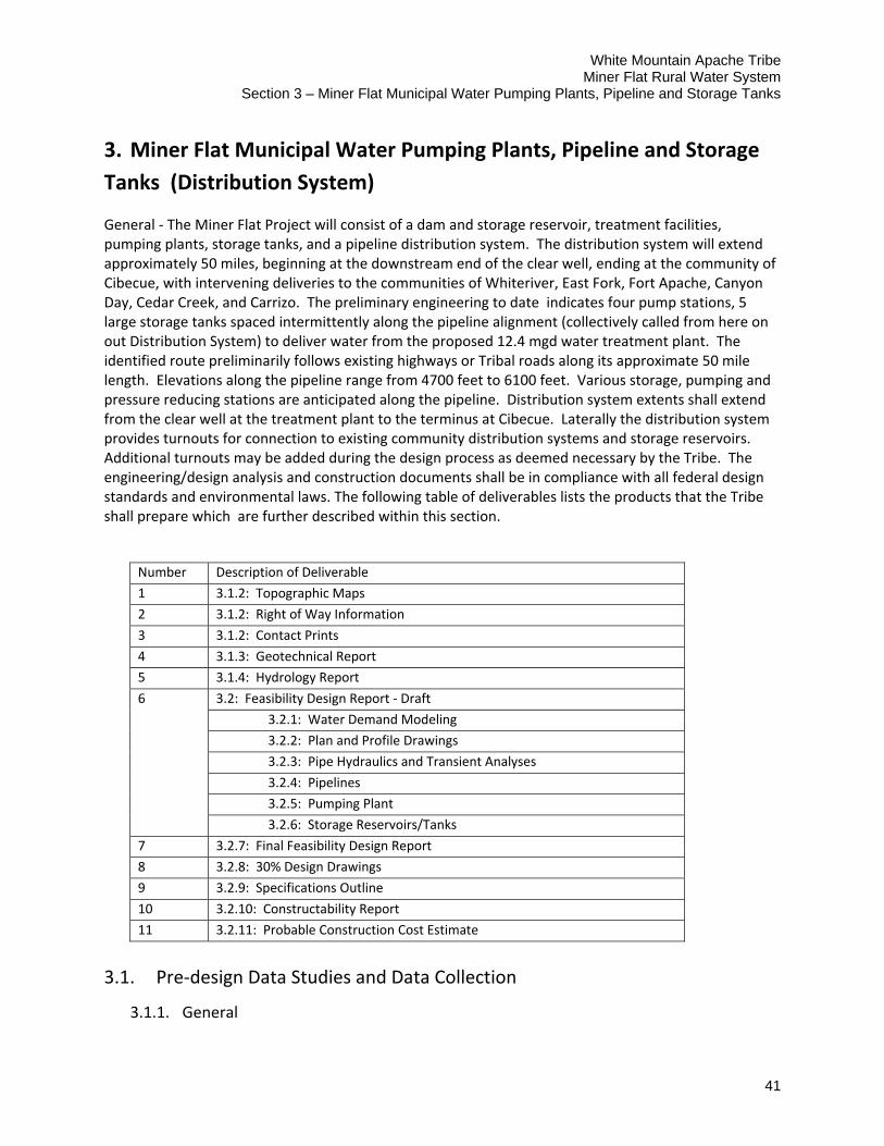
White Mountain Apache Tribe Miner Flat Rural Water System
Section 3 – Miner Flat Municipal Water Pumping Plants, Pipeline and Storage Tanks
41
3. Miner Flat Municipal Water Pumping Plants, Pipeline and Storage
Tanks (Distribution System)
General ‐ The Miner Flat Project will consist of a dam and storage reservoir, treatment facilities, pumping plants, storage tanks, and a pipeline distribution system. The distribution system will extend approximately 50 miles, beginning at the downstream end of the clear well, ending at the community of Cibecue, with intervening deliveries to the communities of Whiteriver, East Fork, Fort Apache, Canyon Day, Cedar Creek, and Carrizo. The preliminary engineering to date indicates four pump stations, 5 large storage tanks spaced intermittently along the pipeline alignment (collectively called from here on out Distribution System) to deliver water from the proposed 12.4 mgd water treatment plant. The identified route preliminarily follows existing highways or Tribal roads along its approximate 50 mile length. Elevations along the pipeline range from 4700 feet to 6100 feet. Various storage, pumping and pressure reducing stations are anticipated along the pipeline. Distribution system extents shall extend from the clear well at the treatment plant to the terminus at Cibecue. Laterally the distribution system provides turnouts for connection to existing community distribution systems and storage reservoirs. Additional turnouts may be added during the design process as deemed necessary by the Tribe. The engineering/design analysis and construction documents shall be in compliance with all federal design standards and environmental laws. The following table of deliverables lists the products that the Tribe shall prepare which are further described within this section.
Number Description of Deliverable
1 3.1.2: Topographic Maps
2 3.1.2: Right of Way Information
3 3.1.2: Contact Prints
4 3.1.3: Geotechnical Report
5 3.1.4: Hydrology Report
6 3.2: Feasibility Design Report ‐ Draft
3.2.1: Water Demand Modeling
3.2.2: Plan and Profile Drawings
3.2.3: Pipe Hydraulics and Transient Analyses
3.2.4: Pipelines
3.2.5: Pumping Plant
3.2.6: Storage Reservoirs/Tanks
7 3.2.7: Final Feasibility Design Report
8 3.2.8: 30% Design Drawings
9 3.2.9: Specifications Outline
10 3.2.10: Constructability Report
11 3.2.11: Probable Construction Cost Estimate
3.1. Pre‐design Data Studies and Data Collection
3.1.1. General
White Mountain Apache Tribe Miner Flat Rural Water System Section 3 – Miner Flat Municipal Water Pumping Plants, Pipeline and Storage Tanks
42
The Distribution System design shall include a comprehensive Feasibility Design Report (FDR). This report shall present the features of construction alternatives within the framework of the Miner Flat Dam Project with sufficient detail to support selection of a selected project configuration which shall be submitted for approval for design and construction. All items that are major cost drivers shall be evaluated and identified in the report. In addition, identification of all major features and considerations that will be required for the project along with preliminary drawings for the major features shall be included in the FDR. For purposes of this study/report, major features shall be defined as those that are consistently 2 percent or more of construction costs. To the degree it is practical, minor items may be quantified and calculated and individually listed.
Alternative layouts and designs shall be provided to determine a preferred design that meets all requirements in the most economical and acceptable manner.
3.1.2. Surveying and Mapping
The Tribe shall provide detailed, controlled aerial photographic information and topography. The Tribe shall be required to identify and develop specific topography and data to facilitate the designs for each specific feature of the Distribution System. Photography shall be flown along the pipeline corridor from the water treatment plant near the Community of Whiteriver, to Cibeque, about 50 miles to the northwest of Whiteriver, generally along Route 73, US 60 and the unpaved road to Cibeque.
Survey Control – Surveys shall be done by a registered land surveyor (RLS) to obtain and monument horizontal and vertical control. Horizontal Control shall be based on the Arizona State Plane Coordinate System, East Zone, 1983 National American Datum (NAD83). Vertical control shall be based on the 1998 National American Vertical Datum (NAVD88)
Topographic Maps – Topographic maps shall be developed at a scale of 1”= 100’ with contour intervals of 2 foot with the underlying aerial photos on the plan views. The maps shall cover the entire project area and shall show and identify existing significant features, natural and manmade and shall include township and range lines, section lines, etc.
Right‐of‐Way Information – Right‐of‐way requirements shall be evaluated and documented in enough detail to determine land acquisition requirements, if any, for permanent and temporary construction including earthwork, haul routes, drainage changes, utility relocations, road crossings, and any construction access restrictions and limitations. Land ownership boundaries and legal jurisdictions shall also be shown
White Mountain Apache Tribe Miner Flat Rural Water System
Section 3 – Miner Flat Municipal Water Pumping Plants, Pipeline and Storage Tanks
43
Right of Way Over Indian Lands – The Tribe shall request and provide for grants for
rights‐of‐way over Indian lands as required in 25 CFR 169
Contact Prints ‐ The Tribe shall provide one set of contact prints made on double‐weight, resin‐coated, semi‐matte finish paper stock, on which ink, pencil, grease pencil, and other commonly employed markers can be used on both sides. All materials, and laboratory processing, developing, reproduction, and printing thereof, shall conform to recognized professional photogrammetric industry standards and practices. All contact prints shall be trimmed to neat and uniform dimensional lines along image edges (without loss of image) leaving distinctly the camera fiducial marks
3.1.3. Geotechnical Investigations
Geotechnical investigations for the Distribution System should explore, analyze and document subsurface conditions at the pumping stations, storage tanks and along the pipeline alignment to provide conclusions and recommendations for the design and construction of the project. The resulting geotechnical report shall include soil conditions and type and permeability, sufficient to establish foundation conditions, excavation unwatering/dewatering requirements (if required), and determine allowable foundation bearing capacities. Specifically, the investigations shall:
Identify seasonal Groundwater elevations (wet and dry periods);
Research historical data relevant to the site;
Identify location and type of rock and soil identified through site borings and/or test pits;
Estimate rock elevations throughout the site;
Make recommendations for excavation and trenching;
Make recommendations for excavation unwatering/dewatering during construction (if required);
Make recommendations for appropriate foundation types for new structures;
Present design criteria for the recommended foundation types;
Make recommendations for temporary and permanent excavation slopes in rock and soil;
Make recommendations for slopes of compacted and uncompacted embankment materials (if required);
Identify engineering soil properties to be used in the structural analysis and design of all structures (above and below ground surface)

White Mountain Apache Tribe Miner Flat Rural Water System Section 3 – Miner Flat Municipal Water Pumping Plants, Pipeline and Storage Tanks
44
Cite construction considerations and potential construction problems, if any;
Identify suitability of on‐site excavation to be used as fill and pipe bedding material.
Present results of soil resistivity tests for pipelines and other project components in accordance with Technical Memorandum No. 8140‐CC‐2004‐1, Corrosion Considerations for Buried Metallic Water Pipe.
3.1.4. Hydrology
The Tribe shall conduct a hydrologic study to ascertain data associated with flows in washes intersecting the pipeline alignment. A hydrology report shall be prepared and will include information on cross‐drainage flows and corresponding water surface elevations as necessary for sighting temporary and permanent facilities located on or near the watercourse. The report shall discuss sediment transport (where and if appropriate) and scour potential at the pipe crossings. The report shall also evaluate runoff from any watershed upslope of the project that may impact project facilities.
3.2. Distribution System Design
The Tribe shall prepare and submit a 30% design submittal package , including design drawings, specifications and construction cost estimate. The Tribe should investigate, analyze and establish the design parameters, design criteria and concepts necessary for preparation of detailed plans and specifications. The process for developing the basic design criteria for this project shall include preparation of a 30% Design Package that includes a draft 30% Design Report (FDR), 30% design drawings, specifications outline, constructability report and probable construction cost estimate. Preliminary layouts of the Distribution System shall be presented at the 30% stage. The following define the requirements under the 30% design submittal:
3.2.1. Water Demand and Modeling
Understanding the water demand for the Miner Flat project shall be important in sizing the pump stations, storage and delivery piping and appurtenances sufficient to deliver water during peak demand. The assumptions and data provided in Chapter 3, Domestic Project Formulation, of the Project Extension Report (2007), should be reviewed and modified to reflect currently available data. From that data, the Tribe shall describe flow requirements of the system, including variability of flow ranges and seasonal delivery requirements.
The Tribe shall consider how to properly accommodate the projected demand values for 2040 while effectively delivering water over the preceding years. These considerations include number and size of pipes, number and size of pumps, disinfectant residual and mixing.
The Tribe shall perform hydraulic modeling using software capable of steady state and extended period simulations along with transient and water quality analysis. The hydraulic model or other network model shall be capable of integrating into GIS or CAD for use during

White Mountain Apache Tribe Miner Flat Rural Water System
Section 3 – Miner Flat Municipal Water Pumping Plants, Pipeline and Storage Tanks
45
operation and maintenance. Hydraulic model inputs shall utilize the same coordinate system as the drawings both horizontal and vertical, in this case Arizona State Plane, East Zone, NAD83, NAVD88. The Tribe should provide the aerial photos or other background imagery in the model for orientation.
3.2.2. Plan and Profile Drawings
Plan and profile drawings shall be included showing preliminary pipeline. Plan and profile drawings should show:
Proposed centerline and stationing a scale at which the hydraulic gradeline, maximum surge pressure gradeline, existing ground surface, and pipeline centerline can easily be viewed
The profile shall show bottom grade, original ground surface, utilities and other subsurface features where they cross the alignment
Location of existing features such as roads, major drainages, and any other features that will affect the location and cost of proposed project facilities
Ties and stationing for turnouts and deliveries, as well as road crossings and utility crossings. Grid coordinates for major structures such as pumping stations, flow control stations, storage reservoirs, etc.
Survey data to include ties to existing features such as existing community distribution systems that may be connected or be otherwise related to project development
Existing ground surface contours and significant topographic features
Low wire elevations and station of power lines (including voltage) where they cross the alignments
Buildings, fences, and other obstructions
Pipe – Hydraulic properties by reaches of proposed features (including hydraulic grade line, pipe dimensions, and pressure class)
Areas where special construction effort is required: low‐density soils, high ground water table, bedrock, etc.
Locations of blow‐offs, air valves and wasteways
3.2.3. Pipe Hydraulics and Transient Analyses
The Tribe shall provide an overall hydraulic analysis of the distribution system. Hydraulic properties should be indicated on the plan and profile drawings. The report shall include:
Transient pressures shall be included in the pipe working pressure designs
White Mountain Apache Tribe Miner Flat Rural Water System Section 3 – Miner Flat Municipal Water Pumping Plants, Pipeline and Storage Tanks
46
The friction analysis equations used for sizing the pipelines and associated coefficients
Maximum and minimum velocity requirements
The effect of hydraulic transients on the system. The Tribe shall modify pipe types, restraints, or add surge suppressors and valve and pump controls as needed to accommodate or mitigate the effects of hydraulic transients
Working pressure defined by the transient pressure up surges
3.2.4. Pipelines
The Tribe shall select pipe material based on system requirements, installation considerations, corrosion resistance requirements, cost etc. appropriate friction loss for material selected and anticipated conditions shall be applied to the hydraulic model. Nominal diameters are not to be used for computations. Select the pipeline material or combinations of materials based on hydraulic modeling results, anticipated soil pressure, drainage crossings, pump station discharge etc. Additionally describe the joints, bedding, cover, and joint restraint required for the pipeline. The 30% pipe design shall consider:
3.2.4.1 Design Codes
State which codes and criteria were used for design, such as American Water Works Association (AWWA), ASTM International standards, etc.
3.2.4.2. Type of Pipe
Describe pipe type alternatives, given computed maximum dynamic pressures, which are suitable for specified design criteria. For each pipe alternative, the Tribe should specify:
Allowable joint types
Bedding requirements
Economic advantages (cost)
Backfill requirements
3.2.4.3. State Requirements for Crossings
Crossings of Roads, Railroads, Canals, Rivers, Utilities, etc. – State requirements for each type of crossing, including allowable pipe type, casing requirements, excavation and backfill requirements, clearance requirements, and burial depth
White Mountain Apache Tribe Miner Flat Rural Water System
Section 3 – Miner Flat Municipal Water Pumping Plants, Pipeline and Storage Tanks
47
3.2.4.4. Valve requirements, including:
Pressure reducing valves
Isolation valves
Control/Turnout valves
Air valves/blow‐off valves
Any other type of valve anticipated
3.2.4.5. Power/Electrical Requirements
Any power requirements for operation of the pipeline including flowmeters, SCADA system, valve operation, corrosion protection etc should be included.
3.2.4.6. Flow Measurement requirements, including:
Location of flowmeters Type of flow measurement required
Accuracy
Type of flowmeters
Telemetry/SCADA
3.2.4.7. Corrosion Protection Requirements
Details on how corrosion potential affects allowable pipe types, lining requirements, and coating requirements with the appropriate corrosion protection measures such as sacrificial anodes, induced current, isolation joints, etc. At a minimum the methods described in Technical Memorandum No 8140‐CC‐2004‐1 Corrosion Consideration for Metallic Water Pipe shall be utilized.
White Mountain Apache Tribe Miner Flat Rural Water System Section 3 – Miner Flat Municipal Water Pumping Plants, Pipeline and Storage Tanks
48
3.2.5. Pumping Plants
System pumps should be modeled based on actual operating curves. Pumping plants shall be designed to effectively accommodate the anticipated gradual increase over time of the demand. The Tribe should identify if commercial package pumping plants are available or if a site built unit is required. Pump station design/acquisition shall consider and address:
Site Layout and Access
Foundation conditions
Excavation details ‐ General layout of the site excavation with sections and details.
Concrete slab/floor requirements
Power Accessibility
Backup/Emergency power
Hydraulic Profile ‐ Provide a clear description of the operating conditions at present and future flow conditions that include the extremes of maximum and minimum flows
Pumping Plant General Arrangement ‐ General arrangement of the building showing the layout of plant equipment, means of egress, rooms, access hatches/doors, etc. Drawings should show a series of plans with numerous sections and details that are necessary to convey the general layout of the facility
Type of pumps with appropriate details
Pump configuration ‐ Number and size of pumps to most effectively meet low and peak demands (current and future)
Pump efficiencies
Redundancy
o Housing/structural requirements ‐ Structural design drawings showing plans, sections, and details of the various structural components
o Chemical storage
o Security
o Remote operability
o Road Access
o Corrosion
o Valving
3.2.6. Storage Reservoirs/Tanks
White Mountain Apache Tribe Miner Flat Rural Water System
Section 3 – Miner Flat Municipal Water Pumping Plants, Pipeline and Storage Tanks
49
The Tribe should review operating criteria presented in the Project Extension Report and confirm that that criteria is still applicable, or adjust as necessary . Tank positioning and size shall provide adequate pressure under static conditions to accommodate delivery to all users on the system.
The storage tanks analysis shall include the selection of the optimal mixing scheme, both for residence time and disinfectant residual. Additionally, appropriate control valves for bypass flow etc. shall be considered. Parameters should include location of inlet and outlet pipelines, baffling in the tanks, or any other physical or mechanical systems required for the tank. At a minimum, storage reservoir designs should consider and address the following:
Site Layout and access
Foundation conditions
Concrete requirements
Valves
Chlorination/detention time
Structural steel/welding requirements
Maintenance
Corrosion protection
Security
Remote sensing (water levels)
3.2.7. 30% Feasibility Design Report (FDR)
All of the foregoing information shall be compiled and incorporated into a comprehensive, bound draft report with conclusions derived as a result of this feasibility level study. Each discreet activity within this scope of work shall be included in the report. The report shall include a title page, table of contents, executive summary and appendices with supporting documentation associated with the study activities. The draft report shall be submitted for review and comment. If determined advantageous, the Tribe shall make a presentation outlining the key aspects.
This report shall present the features of construction alternatives within the framework of the Distribution System with sufficient detail to support selection of a selected project configuration which shall be submitted for approval for design and construction. Alternative layouts and designs shall be provided to determine a preferred design that meets all requirements in the most economical and acceptable manner with comparisons of construction cost and operation, maintenance, and replacement costs used in alternative selection. All items that are major cost drivers shall be evaluated and identified in the report. In addition, identification of all major features and considerations that will be
White Mountain Apache Tribe Miner Flat Rural Water System Section 3 – Miner Flat Municipal Water Pumping Plants, Pipeline and Storage Tanks
50
required for the project along with preliminary drawings for the major features shall be included in the FDR. For purposes of this study/report, major features shall be defined as those that are consistently 2 percent or more of construction costs. To the degree it is practical, minor items may be quantified and calculated and individually listed.
The Tribe shall record all comments received. Each comment shall be addressed. A final report shall be prepared pursuant to discussions, meetings and presentations during the draft review and distributed for final review. Additional comments if any shall be incorporated as appropriate into the final printed report. The report shall be printed, bound and distributed.
3.2.8. 30% Design Drawings
Design drawings for each of the project features shall be completed sufficient to identify and compute major cost items. Drawings for individual components of the project, including the pumping plants, pipeline, control buildings and storage reservoirs shall be prepared sufficient to identify major cost items. Drawings shall conform to the National CAD Standard (NCS).
3.2.8.1. Pipeline Drawings
pipeline drawings should include not be limited to:
General plan view of pipeline alignment
Pump discharge lines
Pipe distribution system details
Typical pipe trench section – Show a typical trench section for each proposed pipe option. The typical pipe section would include minimum earth cover, compaction requirements, frost depth, etc. Also, show typical section for special installation requirements, such as locations where casing is required, and discuss the special installation requirements.
Bedding requirements
Corrosion protection details
Scour protection details at major wash crossings
Crossings of roads, railroads, canals, rivers, washes, utilities, etc. showing requirements for each type of crossing, including pipe type, casing requirements, excavation and backfill requirements, clearance requirements, and burial depth.
Turnouts, including valve details, flow meters, etc.
Air vent and blow‐off details
Other valve details
White Mountain Apache Tribe Miner Flat Rural Water System
Section 3 – Miner Flat Municipal Water Pumping Plants, Pipeline and Storage Tanks
51
o Isolation valves
o Pressure Reducing Valves
Flow measurement design details, including, installation requirements such as length of upstream straight pipe, straightening vanes
Corrosion Protection Details
3.2.8.2. Pumping Plant Drawings
The Tribe should identify if commercial pump stations are available or if a site built unit is required. Design drawings should include but not be limited to:
Station location. Map or figure showing geographic location
Site Plan and access
Pumping Plant General Arrangement drawings showing the general arrangement of the building, showing the layout of plant equipment, means of egress, rooms, access hatches/doors, etc. Drawings should include a series of plans with numerous sections and details that are necessary to convey the general layout of the facility
Structural design drawings showing plans, sections, and details of the various structural components
Power/Electrical details
Discharge lines and manifolds
General plumbing schematic
Preliminary Process and Instrumentation Diagram (P&ID) ‐ Drawing should show main controls, instrumentation and measurement devices.
3.2.8.3. Storage Tanks (Reservoirs)
Design drawings should include but not be limited to:
Sight plan
Tank size/dimensions
Structural design including steel plate thickness, weld details, manhole locations, etc.
Foundation design and steel reinforcement
Internal baffling details

White Mountain Apache Tribe Miner Flat Rural Water System Section 3 – Miner Flat Municipal Water Pumping Plants, Pipeline and Storage Tanks
52
Inlet and outlet details
Valve details
Telemetry details
Access roads
Power/electrical details
Corrosion protection/monitoring details
Chemical injection details
3.2.9. Specifications Outline
The Tribe shall prepare and submit a specifications outline using CSI MasterFormat 2004 Edition.
3.2.10. Constructability Report
A Constructability Report shall be prepared. It shall provide the following critical information in planning the construction phase of the project:
Environmental considerations/requirements that will affect construction and how the design accommodates these requirements
Discussion of construction methods Trenching requirements/shoring Temporary site bypass (detours) requirements for roads, if any Discussion of potential time constraints (duration, start or finish of project or
certain features) A preliminary construction schedule based on relative time frames (i.e., no
dates)
Any extraordinary or uncommon construction requirements
Permits that will likely be required for construction
3.2.11. Construction Cost Estimate
The preliminary (30%) design shall be prepared in sufficient detail to ensure that all items that significantly affect the cost of construction are accounted for in the field cost estimate. The field cost estimate shall be prepared in dollars representing the cost of construction at the time the cost estimate is prepared. Designs shall be completed in enough detail so as to

White Mountain Apache Tribe Miner Flat Rural Water System
Section 3 – Miner Flat Municipal Water Pumping Plants, Pipeline and Storage Tanks
53
limit the allowance of unlisted items and contingencies as described below. The cost estimates shall include the following (as is applicable to this level of estimate):
3.2.11.1. Pay Items
Pay items for the construction of new features of work include both major and minor items. Major items are those that are consistently 2 percent or more of construction costs. Minor items are less than 2 percent of construction costs. All major cost items shall be quantified and estimated individually. Where practical, the quantity and cost for minor items shall be calculated and individually listed in the cost estimate as well.
3.2.11.2. Unit Costs
Market research shall be conducted and existing historic cost data shall be referenced in determining appropriate unit costs for each of the pay items.
3.2.11.3. Field Cost Estimates
Field costs shall be estimated based on computed quantities and unit costs. In addition the field costs shall assume the following:
Allowance for Design Contingencies (Unlisted Items) ‐ This line item in the field cost estimate shall be included to approximate the costs of unlisted minor and undefined items. This percentage shall not exceed 10 percent.
Construction Contingencies ‐ Field cost estimates include a percentage allowance for contingencies as a separate line item to cover minor differences in actual quantities and the quantities estimated during the feasibility design phase, unforeseen difficulties at the site, changed site conditions or possible minor changes in plans after award of construction contract. The contingency allowance for this 30% cost estimate shall not exceed 20 percent of the subtotal of all listed pay items, including allowance for unlisted items.

White Mountain Apache Tribe Miner Flat Rural Water System
Section 4 – Applicable Codes, Standards and Reference Documents
55
4. Applicable Codes, Standards and Reference Documents
The following documents outline many guidelines and requirements for construction of Federal dams which would apply to the proposed Miner Flat Dam. Not all aspects of these documents will apply as many are very broad based and provide direction and policy to Specific Federal Agencies. They are provided as a framework to be referenced during the Tribe’s designs.
If any of the following list of codes, standards and reference documents are updated prior to the design and construction of any of the features, the most current version shall be applied.
4.1. Federal Directives and Guidelines
Reclamation Directives and Standards Federal Guidelines for Dam Safety, 1979 Departmental Manual, 753 DM 2, 2.10, A.
4.2. Reclamation Engineering Monographs
No. 3 ‐ Welded Steel Penstocks, 1966 No. 7 ‐ Friction Factors for Large Conduits Flowing Full, 1977 No. 9 ‐ Discharge Coefficients for Irregular Overfall Spillways, 1952 No. 13 ‐ Estimating Foundation Settlement by One‐Dimensional Consolidation Tests,
1953 No. 19 ‐ Design Criteria for Concrete Arch and Gravity Dams, Revised 1977 No. 25 ‐ Hydraulic Design of Stilling Basins and Energy Dissipators, Revised 1978 No. 31 ‐ Ground‐Water Movement, 1964 No. 32 ‐ Stress Analysis of Wye Branches, 1964 No. 34 ‐ Control of Cracking In Mass Concrete Structures, Revised 1981 No. 41 ‐ Air‐Water Flow in Hydraulic Structures, 1980 No. 42 ‐ Cavitation in Chutes and Spillways, 1990
4.3. ACER* Technical Memoranda
#2 Freeboard Criteria and Guidelines for Computing Freeboard Allowances for Storage Dams, 1992
#3 Criteria and Guidelines for Evacuating Storage Reservoirs and Sizing Low‐Level Outlet Works, 1990
#4 Criteria for Bulkheading Outlet Works Intakes for Storage Dams, 1982 #5 Policy Statements for Grouting, 1984 #8 Guidelines for Designing and Constructing Roller‐Compacted Concrete Dams, 1987 #11 Downstream Hazard Classification Guidelines, 1988
* ACER, Assistant Commissioner – Engineering and Research (part of Reclamation's Denver Office prior to 1994)
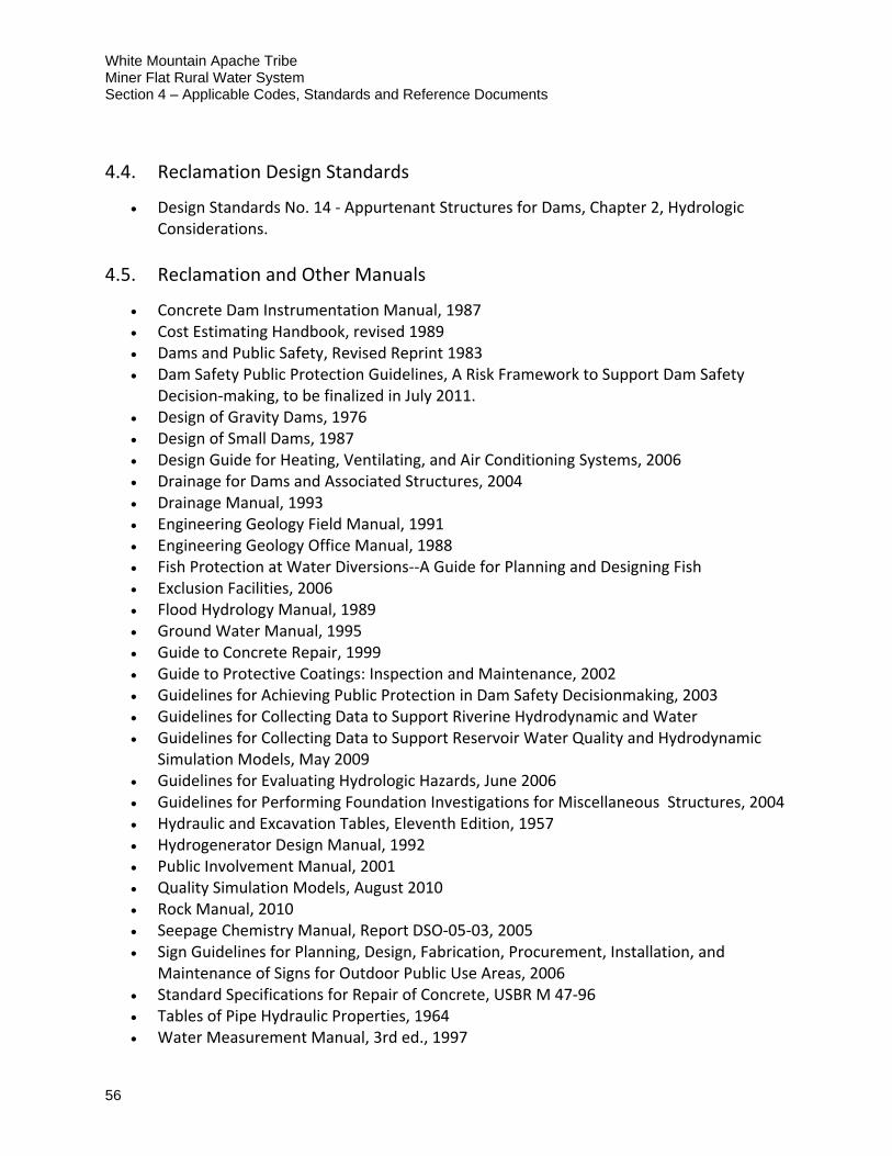
White Mountain Apache Tribe Miner Flat Rural Water System Section 4 – Applicable Codes, Standards and Reference Documents
56
4.4. Reclamation Design Standards
Design Standards No. 14 ‐ Appurtenant Structures for Dams, Chapter 2, Hydrologic Considerations.
4.5. Reclamation and Other Manuals
Concrete Dam Instrumentation Manual, 1987 Cost Estimating Handbook, revised 1989 Dams and Public Safety, Revised Reprint 1983 Dam Safety Public Protection Guidelines, A Risk Framework to Support Dam Safety
Decision‐making, to be finalized in July 2011. Design of Gravity Dams, 1976 Design of Small Dams, 1987 Design Guide for Heating, Ventilating, and Air Conditioning Systems, 2006 Drainage for Dams and Associated Structures, 2004 Drainage Manual, 1993 Engineering Geology Field Manual, 1991 Engineering Geology Office Manual, 1988 Fish Protection at Water Diversions‐‐A Guide for Planning and Designing Fish Exclusion Facilities, 2006 Flood Hydrology Manual, 1989 Ground Water Manual, 1995 Guide to Concrete Repair, 1999 Guide to Protective Coatings: Inspection and Maintenance, 2002 Guidelines for Achieving Public Protection in Dam Safety Decisionmaking, 2003 Guidelines for Collecting Data to Support Riverine Hydrodynamic and Water Guidelines for Collecting Data to Support Reservoir Water Quality and Hydrodynamic
Simulation Models, May 2009 Guidelines for Evaluating Hydrologic Hazards, June 2006 Guidelines for Performing Foundation Investigations for Miscellaneous Structures, 2004 Hydraulic and Excavation Tables, Eleventh Edition, 1957 Hydrogenerator Design Manual, 1992 Public Involvement Manual, 2001 Quality Simulation Models, August 2010 Rock Manual, 2010 Seepage Chemistry Manual, Report DSO‐05‐03, 2005 Sign Guidelines for Planning, Design, Fabrication, Procurement, Installation, and
Maintenance of Signs for Outdoor Public Use Areas, 2006 Standard Specifications for Repair of Concrete, USBR M 47‐96 Tables of Pipe Hydraulic Properties, 1964 Water Measurement Manual, 3rd ed., 1997
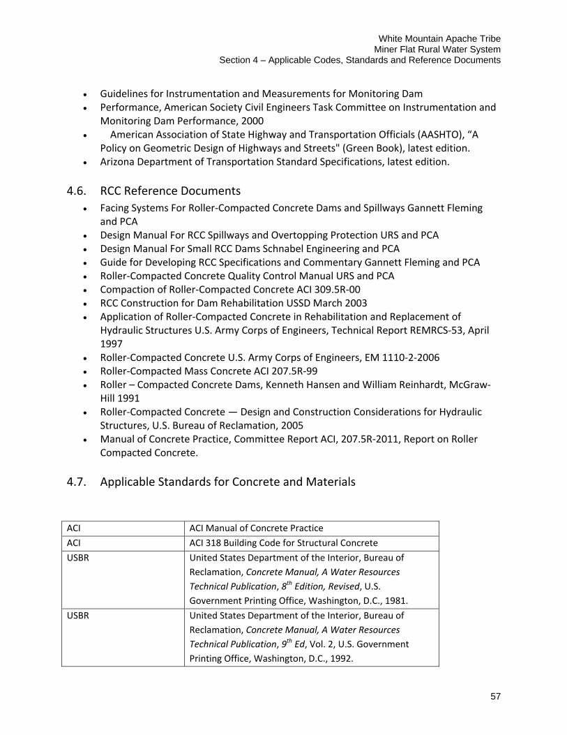
White Mountain Apache Tribe Miner Flat Rural Water System
Section 4 – Applicable Codes, Standards and Reference Documents
57
Guidelines for Instrumentation and Measurements for Monitoring Dam Performance, American Society Civil Engineers Task Committee on Instrumentation and
Monitoring Dam Performance, 2000 American Association of State Highway and Transportation Officials (AASHTO), “A
Policy on Geometric Design of Highways and Streets" (Green Book), latest edition. Arizona Department of Transportation Standard Specifications, latest edition.
4.6. RCC Reference Documents
Facing Systems For Roller‐Compacted Concrete Dams and Spillways Gannett Fleming and PCA
Design Manual For RCC Spillways and Overtopping Protection URS and PCA Design Manual For Small RCC Dams Schnabel Engineering and PCA Guide for Developing RCC Specifications and Commentary Gannett Fleming and PCA Roller‐Compacted Concrete Quality Control Manual URS and PCA Compaction of Roller‐Compacted Concrete ACI 309.5R‐00 RCC Construction for Dam Rehabilitation USSD March 2003 Application of Roller‐Compacted Concrete in Rehabilitation and Replacement of
Hydraulic Structures U.S. Army Corps of Engineers, Technical Report REMRCS‐53, April 1997
Roller‐Compacted Concrete U.S. Army Corps of Engineers, EM 1110‐2‐2006 Roller‐Compacted Mass Concrete ACI 207.5R‐99 Roller – Compacted Concrete Dams, Kenneth Hansen and William Reinhardt, McGraw‐
Hill 1991 Roller‐Compacted Concrete — Design and Construction Considerations for Hydraulic
Structures, U.S. Bureau of Reclamation, 2005 Manual of Concrete Practice, Committee Report ACI, 207.5R‐2011, Report on Roller
Compacted Concrete.
4.7. Applicable Standards for Concrete and Materials
ACI ACI Manual of Concrete Practice
ACI ACI 318 Building Code for Structural Concrete
USBR United States Department of the Interior, Bureau of
Reclamation, Concrete Manual, A Water Resources
Technical Publication, 8th Edition, Revised, U.S.
Government Printing Office, Washington, D.C., 1981.
USBR United States Department of the Interior, Bureau of
Reclamation, Concrete Manual, A Water Resources
Technical Publication, 9th Ed, Vol. 2, U.S. Government
Printing Office, Washington, D.C., 1992.
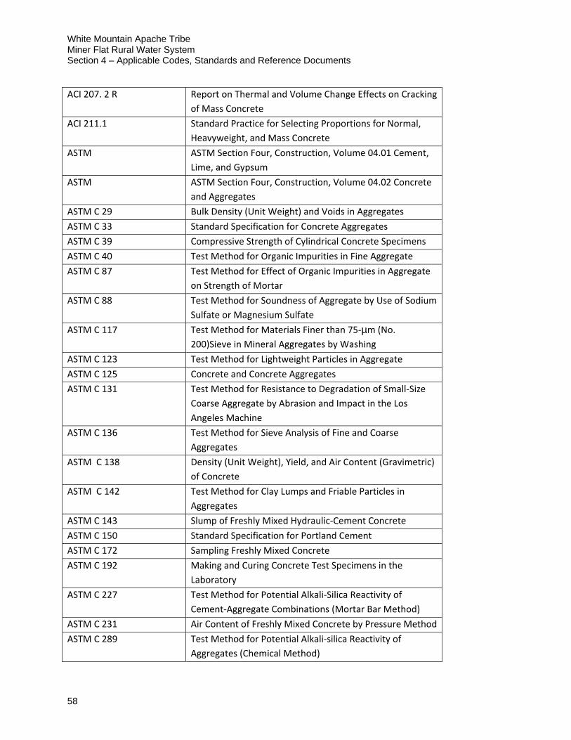
White Mountain Apache Tribe Miner Flat Rural Water System Section 4 – Applicable Codes, Standards and Reference Documents
58
ACI 207. 2 R Report on Thermal and Volume Change Effects on Cracking
of Mass Concrete
ACI 211.1 Standard Practice for Selecting Proportions for Normal,
Heavyweight, and Mass Concrete
ASTM ASTM Section Four, Construction, Volume 04.01 Cement,
Lime, and Gypsum
ASTM ASTM Section Four, Construction, Volume 04.02 Concrete
and Aggregates
ASTM C 29 Bulk Density (Unit Weight) and Voids in Aggregates
ASTM C 33 Standard Specification for Concrete Aggregates
ASTM C 39 Compressive Strength of Cylindrical Concrete Specimens
ASTM C 40 Test Method for Organic Impurities in Fine Aggregate
ASTM C 87 Test Method for Effect of Organic Impurities in Aggregate
on Strength of Mortar
ASTM C 88 Test Method for Soundness of Aggregate by Use of Sodium
Sulfate or Magnesium Sulfate
ASTM C 117 Test Method for Materials Finer than 75‐µm (No.
200)Sieve in Mineral Aggregates by Washing
ASTM C 123 Test Method for Lightweight Particles in Aggregate
ASTM C 125 Concrete and Concrete Aggregates
ASTM C 131 Test Method for Resistance to Degradation of Small‐Size
Coarse Aggregate by Abrasion and Impact in the Los
Angeles Machine
ASTM C 136 Test Method for Sieve Analysis of Fine and Coarse
Aggregates
ASTM C 138 Density (Unit Weight), Yield, and Air Content (Gravimetric)
of Concrete
ASTM C 142 Test Method for Clay Lumps and Friable Particles in
Aggregates
ASTM C 143 Slump of Freshly Mixed Hydraulic‐Cement Concrete
ASTM C 150 Standard Specification for Portland Cement
ASTM C 172 Sampling Freshly Mixed Concrete
ASTM C 192 Making and Curing Concrete Test Specimens in the
Laboratory
ASTM C 227 Test Method for Potential Alkali‐Silica Reactivity of
Cement‐Aggregate Combinations (Mortar Bar Method)
ASTM C 231 Air Content of Freshly Mixed Concrete by Pressure Method
ASTM C 289 Test Method for Potential Alkali‐silica Reactivity of
Aggregates (Chemical Method)

White Mountain Apache Tribe Miner Flat Rural Water System
Section 4 – Applicable Codes, Standards and Reference Documents
59
ASTM C 294 Descriptive Nomenclature for Constituents of Concrete
Aggregates
ASTM C 295 Guide for Petrographic Examination of Aggregates for
Concrete
ASTM C 342 Test Method for Potential Volume Change of Cement‐
Aggregate Combinations
ASTM C 441 Test Method for Effectiveness of Pozzolans or Ground
Blast Furnace Slag in Preventing Excessive Expansion of
Concrete Due to Alkali‐Silica Reaction
ASTM C 469 Static Modulus of Elasticity and Poisson’s Ratio of
Concrete in Compression
ASTM C 512 Creep of Concrete in Compression
ASTM C 535 Test Method for Resistance to Degradation of Large‐Size
Coarse Aggregate by Abrasion and Impact in the Los
Angeles Machine
ASTM C 586 Test Method for Potential Alkali‐Silica Reactivity of
Carbonate Rocks as Concrete Aggregates (Rock‐Cylinder
Method)
ASTM C 595 Specifications for Blended Hydraulic Cements
ASTM C 642 Density, Absorption, and Voids in Hardened Concrete
ASTM C 666 Resistance of Concrete to Rapid Freezing and Thawing
ASTM C 618 Coal Fly Ash or Calcined Natural Pozzolan for Use in
Concrete
ASTM C 989 Slag Cement for Use in Concrete and Mortars
ASTM C 1105 Test Method for Length Change of Concrete Due to Alkali
Carbonate Reaction
ASTM C 1157 Performance Specification for Hydraulic Cement
ASTM C 1170 Determining Consistency and Density of Roller‐Compacted
Concrete Using a Vibrating Table
ASTM C 1176 Making Roller‐Compacted Concrete in Cylinder Molds
Using a Vibrating Hammer
ASTM C 1260 Test Method for Potential Alkali Reactivity of Aggregates
(Mortar Bar Method)
ASTM C 1293 Determination of Length Change of Concrete Due to Alkali‐
silica Reaction
ASTM C 1435 Molding Roller‐Compacted Concrete in Cylinder Molds
Using a Vibrating Table
ASTM C 1567 Test Method for Determining Potential Alkali‐silica
Reactivity of Combinations of Cementitious Materials and

White Mountain Apache Tribe Miner Flat Rural Water System Section 4 – Applicable Codes, Standards and Reference Documents
60
Aggregates (Accelerated Mortar‐Bar Method)
ASTM C 1697 Standard Specifications for Blended Supplementary
Cementitious Materials
D 75 Practice for Sampling Aggregates
D 3665 Practice for Random Sampling of Construction Materials
E 11 Specification for Woven Wire Test Sieve Cloth and Test
Sieves
4.8. Applicable Standards for Coatings and Linings
ASTM Standard No.
ASTM A 380‐06 Cleaning, Descaling, and Passivation of Stainless Steel Parts,
Equipment, and Systems
ASTM A 780‐01(2009) Repair of Damaged and Uncoated Areas of Hot Dip Galvanized
Coatings
ASTM B 117‐09 Standard Practice for Operating Salt Spray (Fog) Apparatus
ASTM C 920‐11 Elastomeric Joint Sealants
ASTM D 522‐93a(2008) Mandrel Bend Test of Attached Organic Coatings
ASTM D 570‐98(2010) Water absorption of Plastics
ASTM D 638‐10 Tensile Strength of Plastics
ASTM D 695‐10 Compressive Properties of Rigid Plastics
ASTM D 790‐10 Flexural Properties of Unreinforced and Reinforced Plastics and
Electrical Insulating Materials
ASTM D 870‐09 Testing Water Resistance of Coatings Using Water Immersion
ASTM D 1002‐10 Apparent Shear Strength of Single‐Lap‐Joint Adhesively Bonded Metal
Specimen by Tension Loading (Metal‐to‐Metal)
ASTM D 1141‐98(2008) Preparation of Substitute Ocean Water
ASTM D 1876‐08 Standard Test Method for Peel Resistance of Adhesives (T‐Peel Test)
ASTM D 2240‐05(2010) Rubber Properties – Durometer Hardness
ASTM D 2244‐09b Calculation of Color Differences From Instrumentally Measured Color
Coordinates
ASTM D 2370‐98(2010) Tensile Properties of Organic Coatings
ASTM D 2794‐93(2010) Resistance of Organic Coatings to the Effects of Rapid Deformation
(Impact)
ASTM D 3359‐09e2 Measuring Adhesion by Tape Test
ASTM D 3363‐05 Film Hardness by Pencil Test
ASTM D 4060‐10 Abrasion Resistance of Organic Coatings by the Taber Abraser

White Mountain Apache Tribe Miner Flat Rural Water System
Section 4 – Applicable Codes, Standards and Reference Documents
61
ASTM D 4138‐07a Evaluating the Degree of Chalking of Exterior Paint Films
ASTM D 4214‐07 Evaluating the Degree of Chalking of Exterior Paint Films
ASTM D 4259‐88(2006) Abrading Concrete
ASTM D 4285‐83(2006) Indicating Oil or Water in Compressed Air
ASTM D 4414‐95(2007) Measurement of Wet Film Thickness by Notch Gages
ASTM D 4541‐09e1 Pull‐Off Strength of Coatings Using Portable Adhesion Testers
ASTM D 4587‐05 Conducting Tests on Paint and Related Coatings and Materials Using a
Fluorescent UV‐Condensation Light‐ and Water‐Exposure Apparatus
ASTM D 4787‐08 Continuity Verification of Liquid or Sheet Linings Applied to Concrete
Substrates
ASTM D 5894‐10 Cyclic Salt Fog/UV Exposure of painted Metal, (Alternating Exposures
in a Fog/Dry Cabinet and a UV/Condensation Cabinet)
ASTM D 6132‐08 Nondestructive Measurement of Dry Film Thickness of Applied
Organic Coatings Over Concrete Using an Ultrasonic Gage
ASTM F 1869‐04 Measuring Moisture Vapor Emission Rate of Concrete Subfloor Using
Anhydrous Calcium Chloride
ASTM G 8‐96(2010) Cathodic Disbonding of Pipeline Coatings
ASTM G 14‐04(2010) Impact Resistance of Pipeline Coatings (Falling Weight Test
ASTM G 32‐11 Cavitation Erosion using Vibratory Apparatus
ASTM G 132‐96(2007) Pin Abrasion Testing
ASTM G 134‐95(2010) Erosion of Solid Materials by a Cavitating Liquid Jet
ASTM G 154‐06 Operating Fluorescent Light Apparatus for UV Exposure of
Nonmetallic Materials
American Water Works
(AWWA)
AWWA C 203‐08 Coal‐Tar Protective Coatings and Linings for Steel Water Pipelines –
Enamel and Tape – Hot Applied
AWWA C 222‐08 Polyurethane Coatings for the Interior and Exterior of Steel Pipe and
Fittings
AWWA C 224‐06 Two‐Layer Nylon‐11‐Based Polyamide Coating System for the Interior
and Exterior of Steel Water Pipe, Connections, Fittings, and Special
Connections
Federal Standard (Fed Std)
Fed Std 595C(1)‐08 Colors Used in Government Procurement
International Organization For Standardization (ISO)
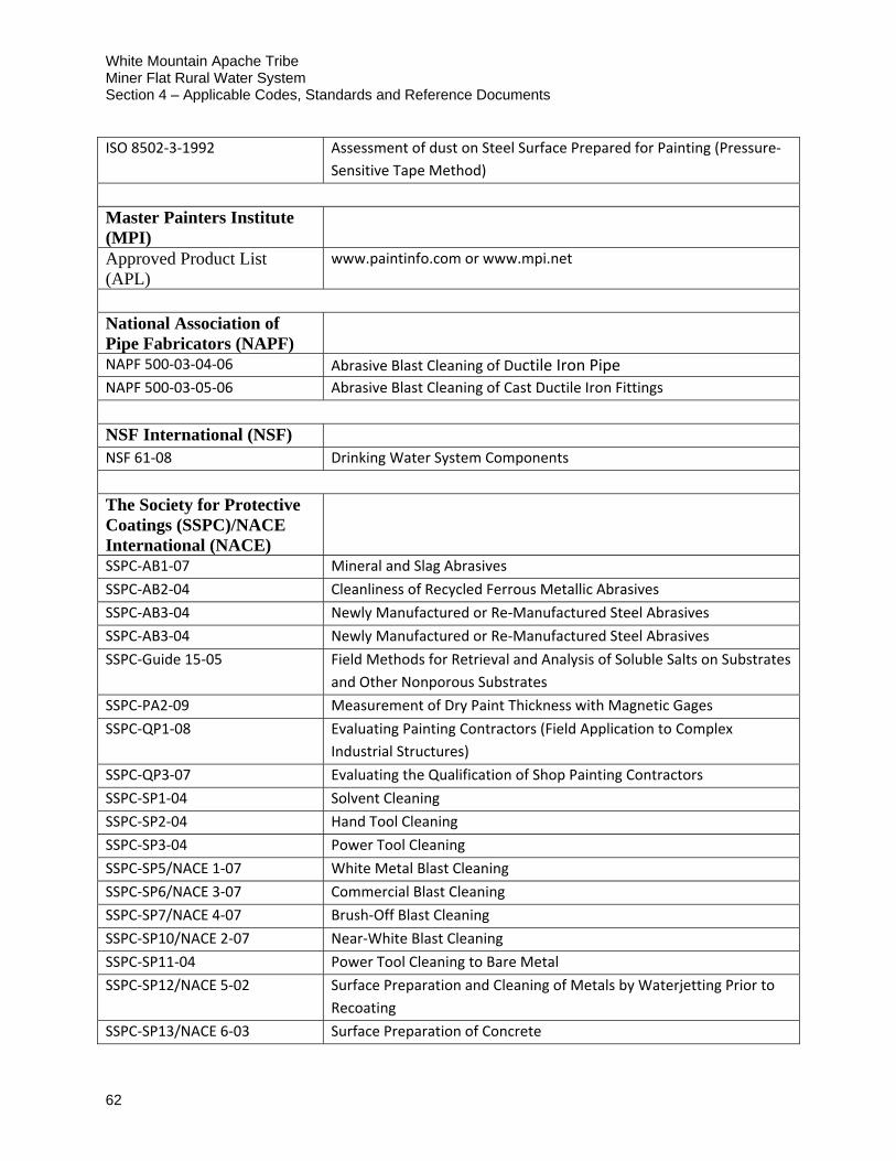
White Mountain Apache Tribe Miner Flat Rural Water System Section 4 – Applicable Codes, Standards and Reference Documents
62
ISO 8502‐3‐1992 Assessment of dust on Steel Surface Prepared for Painting (Pressure‐
Sensitive Tape Method)
Master Painters Institute (MPI)
Approved Product List (APL)
www.paintinfo.com or www.mpi.net
National Association of Pipe Fabricators (NAPF)
NAPF 500‐03‐04‐06 Abrasive Blast Cleaning of Ductile Iron Pipe NAPF 500‐03‐05‐06 Abrasive Blast Cleaning of Cast Ductile Iron Fittings
NSF International (NSF)
NSF 61‐08 Drinking Water System Components
The Society for Protective Coatings (SSPC)/NACE International (NACE)
SSPC‐AB1‐07 Mineral and Slag Abrasives
SSPC‐AB2‐04 Cleanliness of Recycled Ferrous Metallic Abrasives
SSPC‐AB3‐04 Newly Manufactured or Re‐Manufactured Steel Abrasives
SSPC‐AB3‐04 Newly Manufactured or Re‐Manufactured Steel Abrasives
SSPC‐Guide 15‐05 Field Methods for Retrieval and Analysis of Soluble Salts on Substrates
and Other Nonporous Substrates
SSPC‐PA2‐09 Measurement of Dry Paint Thickness with Magnetic Gages
SSPC‐QP1‐08 Evaluating Painting Contractors (Field Application to Complex
Industrial Structures)
SSPC‐QP3‐07 Evaluating the Qualification of Shop Painting Contractors
SSPC‐SP1‐04 Solvent Cleaning
SSPC‐SP2‐04 Hand Tool Cleaning
SSPC‐SP3‐04 Power Tool Cleaning
SSPC‐SP5/NACE 1‐07 White Metal Blast Cleaning
SSPC‐SP6/NACE 3‐07 Commercial Blast Cleaning
SSPC‐SP7/NACE 4‐07 Brush‐Off Blast Cleaning
SSPC‐SP10/NACE 2‐07 Near‐White Blast Cleaning
SSPC‐SP11‐04 Power Tool Cleaning to Bare Metal
SSPC‐SP12/NACE 5‐02 Surface Preparation and Cleaning of Metals by Waterjetting Prior to
Recoating
SSPC‐SP13/NACE 6‐03 Surface Preparation of Concrete
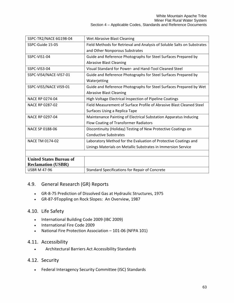
White Mountain Apache Tribe Miner Flat Rural Water System
Section 4 – Applicable Codes, Standards and Reference Documents
63
SSPC‐TR2/NACE 6G198‐04 Wet Abrasive Blast Cleaning
SSPC‐Guide 15‐05 Field Methods for Retrieval and Analysis of Soluble Salts on Substrates
and Other Nonporous Substrates
SSPC‐VIS1‐04 Guide and Reference Photographs for Steel Surfaces Prepared by
Abrasive Blast Cleaning
SSPC‐VIS3‐04 Visual Standard for Power‐ and Hand‐Tool Cleaned Steel
SSPC‐VIS4/NACE‐VIS7‐01 Guide and Reference Photographs for Steel Surfaces Prepared by
Waterjetting
SSPC‐VIS5/NACE VIS9‐01 Guide and Reference Photographs for Steel Surfaces Prepared by Wet
Abrasive Blast Cleaning
NACE RP 0274‐04 High Voltage Electrical Inspection of Pipeline Coatings
NACE RP 0287‐02 Field Measurement of Surface Profile of Abrasive Blast Cleaned Steel
Surfaces Using a Replica Tape
NACE RP 0297‐04 Maintenance Painting of Electrical Substation Apparatus Inducing
Flow Coating of Transformer Radiators
NACE SP 0188‐06 Discontinuity (Holiday) Testing of New Protective Coatings on
Conductive Substrates
NACE TM 0174‐02 Laboratory Method for the Evaluation of Protective Coatings and
Linings Materials on Metallic Substrates in Immersion Service
United States Bureau of Reclamation (USBR)
USBR M 47‐96 Standard Specifications for Repair of Concrete
4.9. General Research (GR) Reports
GR‐8‐75 Prediction of Dissolved Gas at Hydraulic Structures, 1975 GR‐87‐9Toppling on Rock Slopes: An Overview, 1987
4.10. Life Safety
International Building Code 2009 (IBC 2009) International Fire Code 2009 National Fire Protection Association – 101‐06 (NFPA 101)
4.11. Accessibility
Architectural Barriers Act Accessibility Standards
4.12. Security
Federal Interagency Security Committee (ISC) Standards
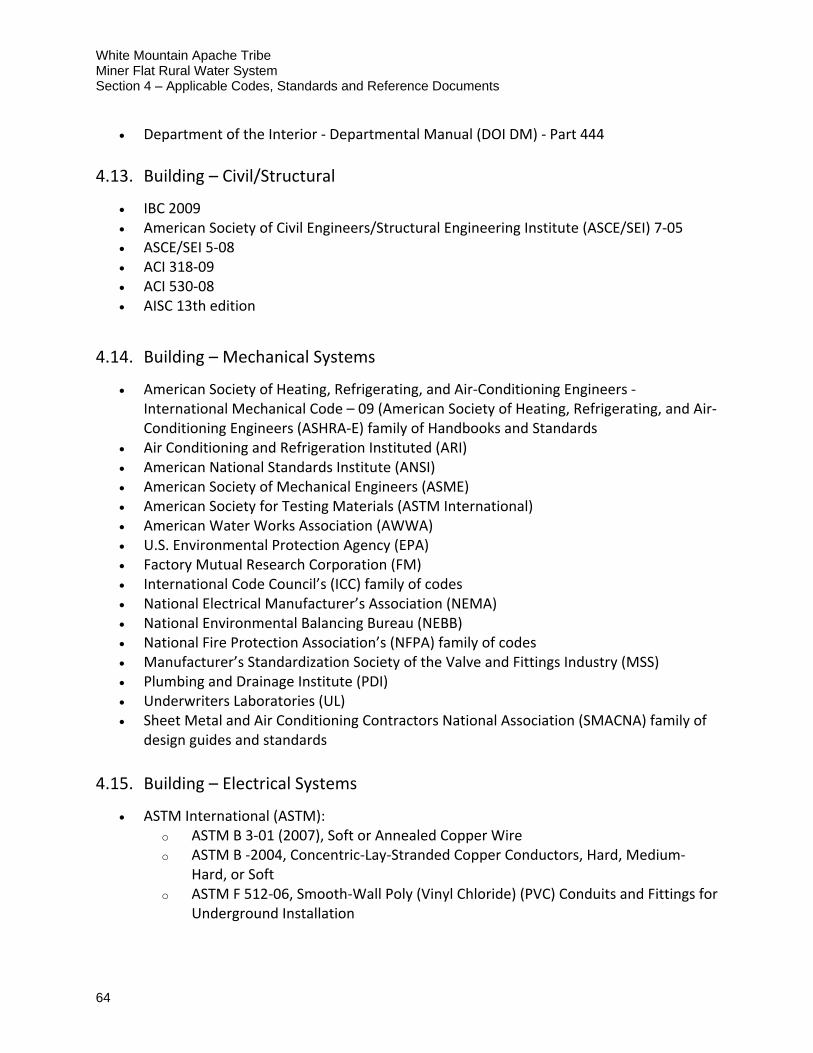
White Mountain Apache Tribe Miner Flat Rural Water System Section 4 – Applicable Codes, Standards and Reference Documents
64
Department of the Interior ‐ Departmental Manual (DOI DM) ‐ Part 444
4.13. Building – Civil/Structural
IBC 2009 American Society of Civil Engineers/Structural Engineering Institute (ASCE/SEI) 7‐05 ASCE/SEI 5‐08 ACI 318‐09 ACI 530‐08 AISC 13th edition
4.14. Building – Mechanical Systems
American Society of Heating, Refrigerating, and Air‐Conditioning Engineers ‐ International Mechanical Code – 09 (American Society of Heating, Refrigerating, and Air‐Conditioning Engineers (ASHRA‐E) family of Handbooks and Standards
Air Conditioning and Refrigeration Instituted (ARI) American National Standards Institute (ANSI) American Society of Mechanical Engineers (ASME) American Society for Testing Materials (ASTM International) American Water Works Association (AWWA) U.S. Environmental Protection Agency (EPA) Factory Mutual Research Corporation (FM) International Code Council’s (ICC) family of codes National Electrical Manufacturer’s Association (NEMA) National Environmental Balancing Bureau (NEBB) National Fire Protection Association’s (NFPA) family of codes Manufacturer’s Standardization Society of the Valve and Fittings Industry (MSS) Plumbing and Drainage Institute (PDI) Underwriters Laboratories (UL) Sheet Metal and Air Conditioning Contractors National Association (SMACNA) family of
design guides and standards
4.15. Building – Electrical Systems
ASTM International (ASTM): o ASTM B 3‐01 (2007), Soft or Annealed Copper Wire o ASTM B ‐2004, Concentric‐Lay‐Stranded Copper Conductors, Hard, Medium‐
Hard, or Soft o ASTM F 512‐06, Smooth‐Wall Poly (Vinyl Chloride) (PVC) Conduits and Fittings for
Underground Installation
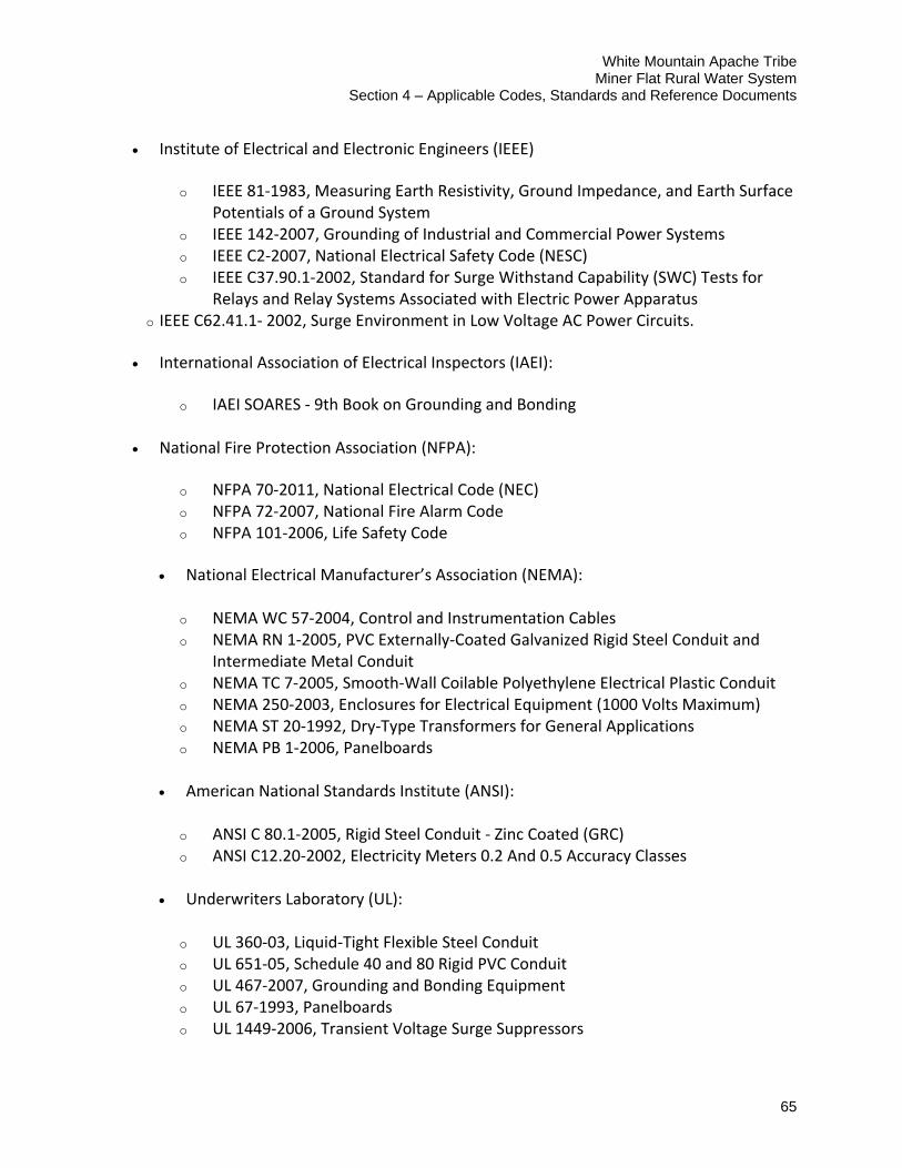
White Mountain Apache Tribe Miner Flat Rural Water System
Section 4 – Applicable Codes, Standards and Reference Documents
65
Institute of Electrical and Electronic Engineers (IEEE)
o IEEE 81‐1983, Measuring Earth Resistivity, Ground Impedance, and Earth Surface Potentials of a Ground System
o IEEE 142‐2007, Grounding of Industrial and Commercial Power Systems o IEEE C2‐2007, National Electrical Safety Code (NESC) o IEEE C37.90.1‐2002, Standard for Surge Withstand Capability (SWC) Tests for
Relays and Relay Systems Associated with Electric Power Apparatus o IEEE C62.41.1‐ 2002, Surge Environment in Low Voltage AC Power Circuits.
International Association of Electrical Inspectors (IAEI):
o IAEI SOARES ‐ 9th Book on Grounding and Bonding
National Fire Protection Association (NFPA):
o NFPA 70‐2011, National Electrical Code (NEC) o NFPA 72‐2007, National Fire Alarm Code o NFPA 101‐2006, Life Safety Code
National Electrical Manufacturer’s Association (NEMA):
o NEMA WC 57‐2004, Control and Instrumentation Cables o NEMA RN 1‐2005, PVC Externally‐Coated Galvanized Rigid Steel Conduit and
Intermediate Metal Conduit o NEMA TC 7‐2005, Smooth‐Wall Coilable Polyethylene Electrical Plastic Conduit o NEMA 250‐2003, Enclosures for Electrical Equipment (1000 Volts Maximum) o NEMA ST 20‐1992, Dry‐Type Transformers for General Applications o NEMA PB 1‐2006, Panelboards
American National Standards Institute (ANSI):
o ANSI C 80.1‐2005, Rigid Steel Conduit ‐ Zinc Coated (GRC) o ANSI C12.20‐2002, Electricity Meters 0.2 And 0.5 Accuracy Classes
Underwriters Laboratory (UL):
o UL 360‐03, Liquid‐Tight Flexible Steel Conduit o UL 651‐05, Schedule 40 and 80 Rigid PVC Conduit o UL 467‐2007, Grounding and Bonding Equipment o UL 67‐1993, Panelboards o UL 1449‐2006, Transient Voltage Surge Suppressors

White Mountain Apache Tribe Miner Flat Rural Water System Section 4 – Applicable Codes, Standards and Reference Documents
66
o UL 489‐2002, Safety Molded‐Case Circuit Breakers, Molded‐Case Switches, and Circuit‐Breaker Enclosures
o UL 1561‐1999, Dry‐Type General Purpose and Power
4.16. Additional Reference Documents
Project Extension Report (February 2007).