Embed Size (px)
Citation preview
Copyright © Siemens AG 2009 - All rights reserved No portion of this document may be reproduced either mechanically
or electronically without the prior consent of Siemens.
WMEA Conference ABC’s of AC Induction Motors
Presented By:
Jim Bender – Business Development Mgr, Siemens
Ben Flick – Product Eng Mgr, Siemens
May 29, 2014
Rapid City, South Dakota
Copyright © Siemens AG 2009 - All rights reserved No portion of this document may be reproduced either mechanically or electronically without the prior consent of Siemens.
Motor Standards
National Electrical Manufacturers Association
NEMA Standards Publication MG1 – Motors and Generators
www.nema.org
International Electrotechnical Commision
IEC 60034-1
www.iec.ch/

Copyright © Siemens AG 2009 - All rights reserved No portion of this document may be reproduced either mechanically or electronically without the prior consent of Siemens.
What are considered “NEMA” motors…
Horsepower
1-500 HP
Speeds
3600, 1800, 1200, 900 RPM
Mounting
Horizontal
Flange Mounted
Vertical
Enclosures
ODP, TEFC, TENV, XP
Voltage (3-phase)
208, 230, 460, 575, 600V
Frequency
60 Hz
Frame sizes
143T-449T
Standards
NEMA, ANSI, IEEE, U.L.,
C.S.A., API and other applicable
US, Canadian and Mexican
Standards

Copyright © Siemens AG 2009 - All rights reserved No portion of this document may be reproduced either mechanically or electronically without the prior consent of Siemens.
Low Voltage TEFC Enclosure Frame Assignments

Copyright © Siemens AG 2009 - All rights reserved No portion of this document may be reproduced either mechanically or electronically without the prior consent of Siemens.
What is a “severe duty” motor??
A motor designed for use in a harsh, indoor or outdoor application. TEFC
enclosure all cast iron construction, NEMA ™ Premium efficient (IEEE-841
specification?).

Copyright © Siemens AG 2009 - All rights reserved No portion of this document may be reproduced either mechanically or electronically without the prior consent of Siemens.
Page 6
Specifications – Motors
General
Horsepower, Speed, Voltage, Frequency
Construction Specific
Enclosure, Stator Construction, Rotor Construction, Bearing Type, Lubrication
Performance Specific
Temperature Rise, Starting conditions, Vibration
Monitoring Accessories
RTDs, Vibration Probes, Switches, Surge Protection
Copyright © Siemens AG 2009 - All rights reserved No portion of this document may be reproduced either mechanically or electronically without the prior consent of Siemens.
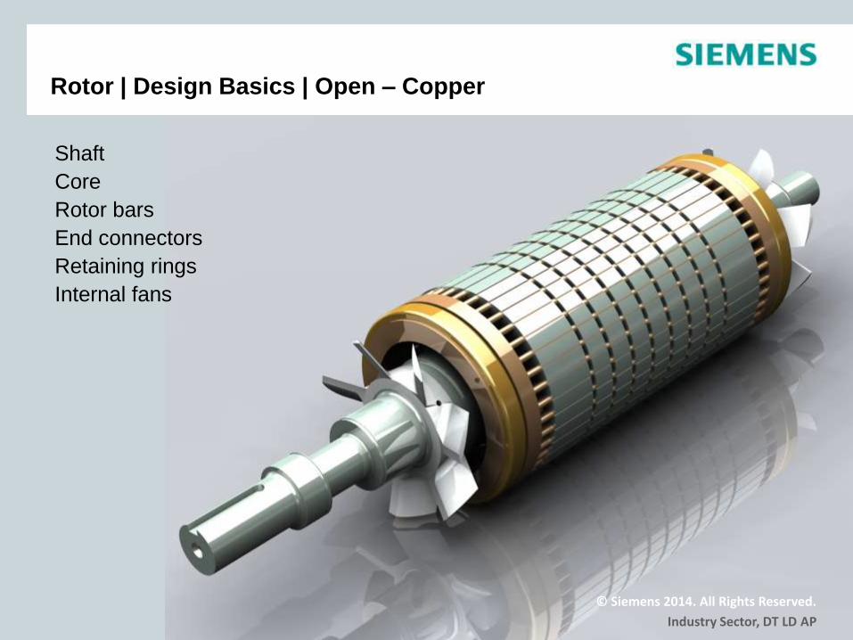
Shaft
Core
Rotor bars
End connectors
Retaining rings
Internal fans
© Siemens 2014. All Rights Reserved.
Industry Sector, DT LD AP
Rotor | Design Basics | Open – Copper

Copyright © Siemens AG 2009 - All rights reserved No portion of this document may be reproduced either mechanically or electronically without the prior consent of Siemens.
Shaft
Core
Rotor bars / End connectors (ADC)
Air duct
Internal fan
External fan
© Siemens 2014. All Rights Reserved.
Industry Sector, DT LD AP
Rotor | Design Basics | TEFC – ADC
Copyright © Siemens AG 2009 - All rights reserved No portion of this document may be reproduced either mechanically or electronically without the prior consent of Siemens.
Page 9
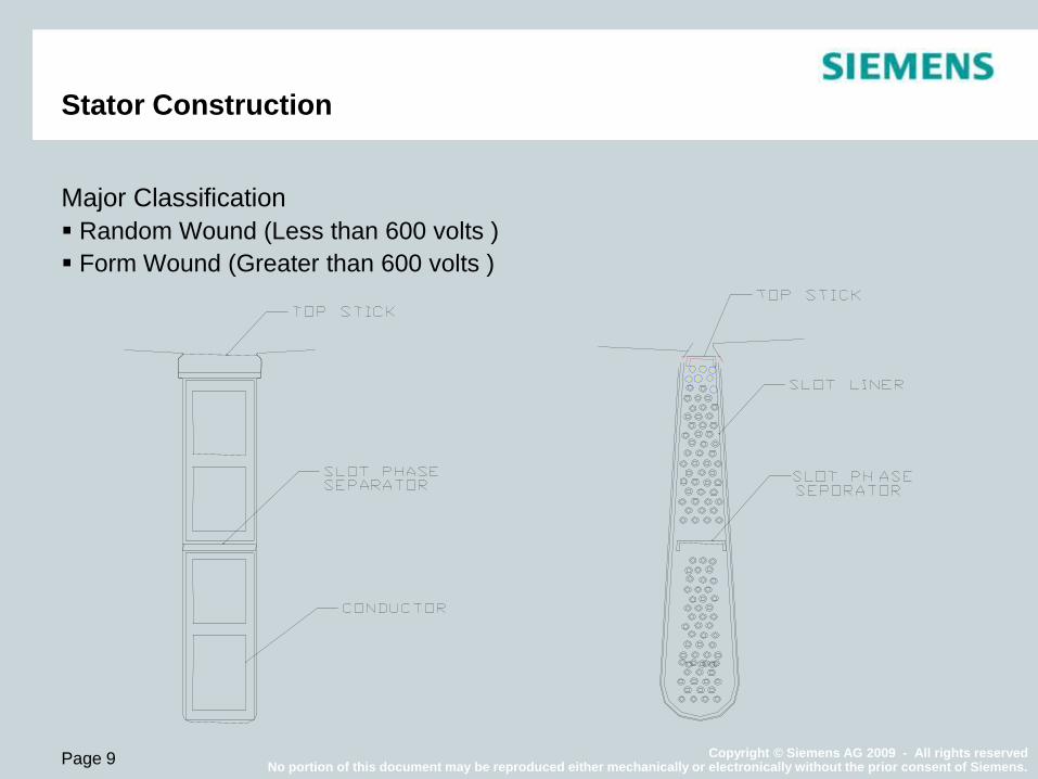
Stator Construction
Major Classification
Random Wound (Less than 600 volts )
Form Wound (Greater than 600 volts )
Copyright © Siemens AG 2009 - All rights reserved No portion of this document may be reproduced either mechanically or electronically without the prior consent of Siemens.
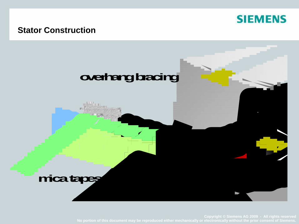
Stator Construction
coil-sidecorona shielding
stress grading
mica tapes
strand insulation
overhang bracing
slot wedge
covering tape
main insulation
Copyright © Siemens AG 2009 - All rights reserved No portion of this document may be reproduced either mechanically or electronically without the prior consent of Siemens.
Page 11
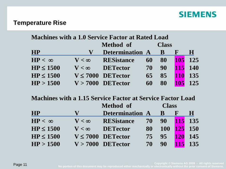
Temperature Rise
Machines with a 1.0 Service Factor at Rated Load
Method of Class
HP V Determination A B F H
HP < V < RESistance 60 80 105 125
HP 1500 V < DETector 70 90 115 140
HP 1500 V 7000 DETector 65 85 110 135
HP > 1500 V > 7000 DETector 60 80 105 125
Machines with a 1.15 Service Factor at Service Factor Load
Method of Class
HP V Determination A B F H
HP < V < RESistance 70 90 115 135
HP 1500 V < DETector 80 100 125 150
HP 1500 V 7000 DETector 75 95 120 145
HP > 1500 V > 7000 DETector 70 90 115 135

Copyright © Siemens AG 2009 - All rights reserved No portion of this document may be reproduced either mechanically or electronically without the prior consent of Siemens.
Page 12
Temperature Rise – Hot Spot
Allowance for Hot Spots
More accurate temperature
measurements (Ex. RTDs) allow
higher limits (On-line Testing)

Copyright © Siemens AG 2009 - All rights reserved No portion of this document may be reproduced either mechanically or electronically without the prior consent of Siemens.
Page 13
Monitoring – Accessories - Stator
Location of the temperature
detector is important!
Ideally located in the hot spot,
especially if blind limits are
used.
Thermistors
RTDs
Stator Winding Temperature Protection
Thermocouples
Thermostats
Copyright © Siemens AG 2009 - All rights reserved No portion of this document may be reproduced either mechanically or electronically without the prior consent of Siemens.
Page 14
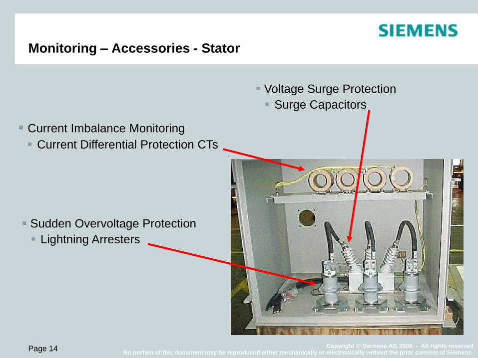
Monitoring – Accessories - Stator
Voltage Surge Protection
Surge Capacitors
Current Imbalance Monitoring
Current Differential Protection CTs
Sudden Overvoltage Protection
Lightning Arresters
Copyright © Siemens AG 2009 - All rights reserved No portion of this document may be reproduced either mechanically or electronically without the prior consent of Siemens.
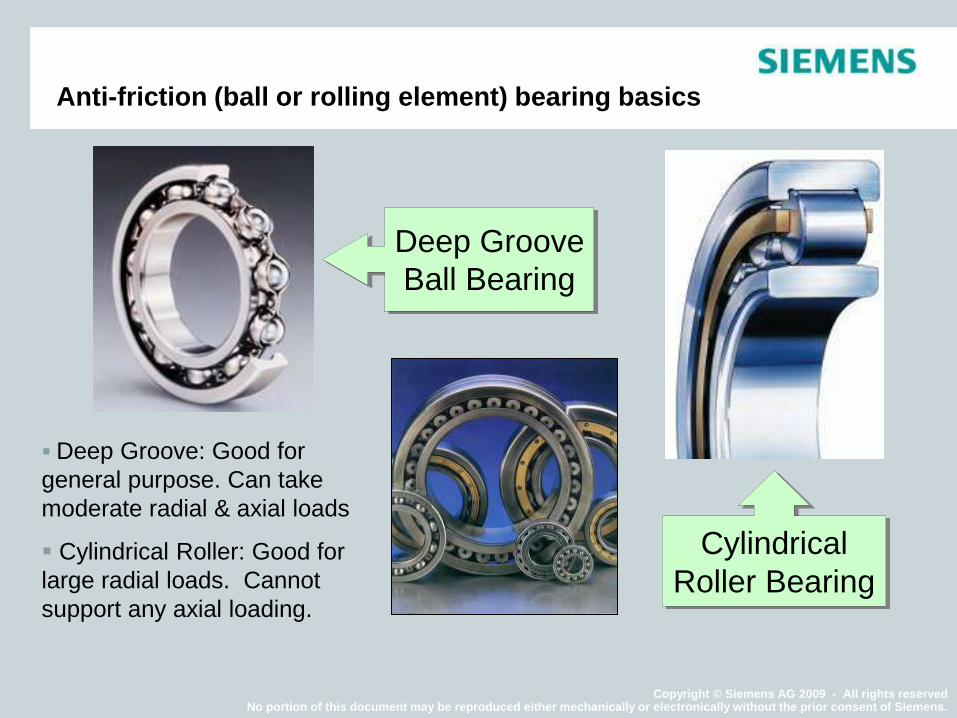
Deep Groove: Good for
general purpose. Can take
moderate radial & axial loads
Cylindrical Roller: Good for
large radial loads. Cannot
support any axial loading.
Anti-friction (ball or rolling element) bearing basics
Deep Groove
Ball Bearing
Cylindrical
Roller Bearing
Copyright © Siemens AG 2009 - All rights reserved No portion of this document may be reproduced either mechanically or electronically without the prior consent of Siemens.
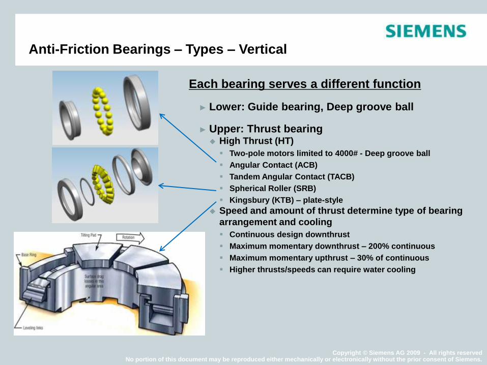
Each bearing serves a different function
► Lower: Guide bearing, Deep groove ball
► Upper: Thrust bearing High Thrust (HT)
Two-pole motors limited to 4000# - Deep groove ball
Angular Contact (ACB)
Tandem Angular Contact (TACB)
Spherical Roller (SRB)
Kingsbury (KTB) – plate-style
Speed and amount of thrust determine type of bearing
arrangement and cooling
Continuous design downthrust
Maximum momentary downthrust – 200% continuous
Maximum momentary upthrust – 30% of continuous
Higher thrusts/speeds can require water cooling
Anti-Friction Bearings – Types – Vertical
Copyright © Siemens AG 2009 - All rights reserved No portion of this document may be reproduced either mechanically or electronically without the prior consent of Siemens.
Page 17
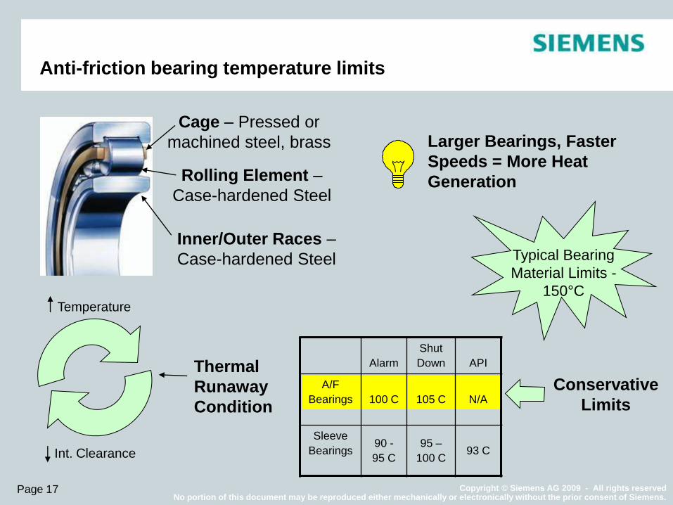
Anti-friction bearing temperature limits
Alarm
Shut
Down API
A/F
Bearings 100 C 105 C N/A
Sleeve
Bearings 90 -
95 C
95 –
100 C 93 C
Cage – Pressed or
machined steel, brass
Rolling Element –
Case-hardened Steel
Inner/Outer Races –
Case-hardened Steel Typical Bearing
Material Limits -
150°C
Conservative
Limits
Larger Bearings, Faster
Speeds = More Heat
Generation
Temperature
Int. Clearance
Thermal
Runaway
Condition
Copyright © Siemens AG 2009 - All rights reserved No portion of this document may be reproduced either mechanically or electronically without the prior consent of Siemens.
Page 18
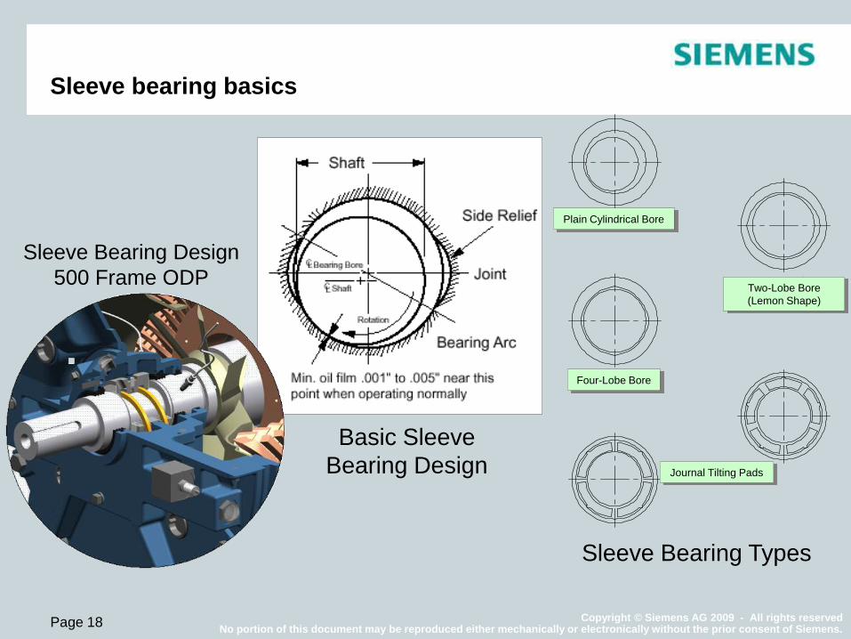
Sleeve bearing basics
Sleeve Bearing Types
Basic Sleeve
Bearing Design
Sleeve Bearing Design
500 Frame ODP
Plain Cylindrical Bore
Journal Tilting Pads
Four-Lobe Bore
Two-Lobe Bore
(Lemon Shape)
Copyright © Siemens AG 2009 - All rights reserved No portion of this document may be reproduced either mechanically or electronically without the prior consent of Siemens.
Page 19
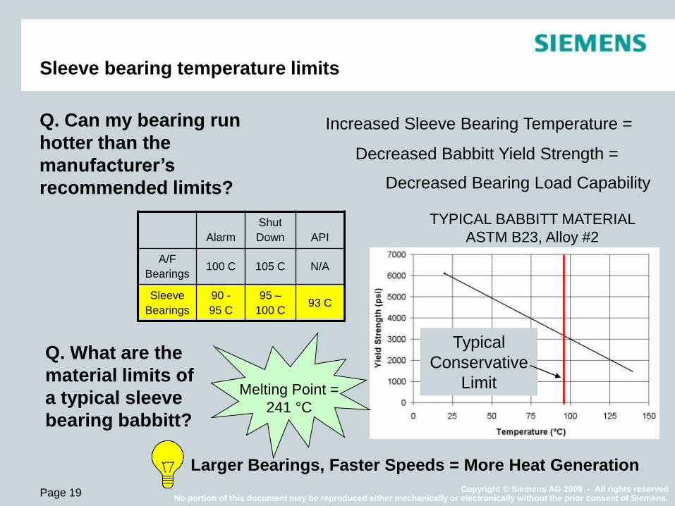
Sleeve bearing temperature limits
TYPICAL BABBITT MATERIAL
ASTM B23, Alloy #2
Increased Sleeve Bearing Temperature =
Decreased Babbitt Yield Strength =
Decreased Bearing Load Capability
Melting Point =
241 °C
Typical
Conservative
Limit
Alarm
Shut
Down API
A/F
Bearings 100 C 105 C N/A
Sleeve
Bearings
90 -
95 C
95 –
100 C 93 C
Q. What are the
material limits of
a typical sleeve
bearing babbitt?
Larger Bearings, Faster Speeds = More Heat Generation
Q. Can my bearing run
hotter than the
manufacturer’s
recommended limits?
Copyright © Siemens AG 2009 - All rights reserved No portion of this document may be reproduced either mechanically or electronically without the prior consent of Siemens.
Page 20
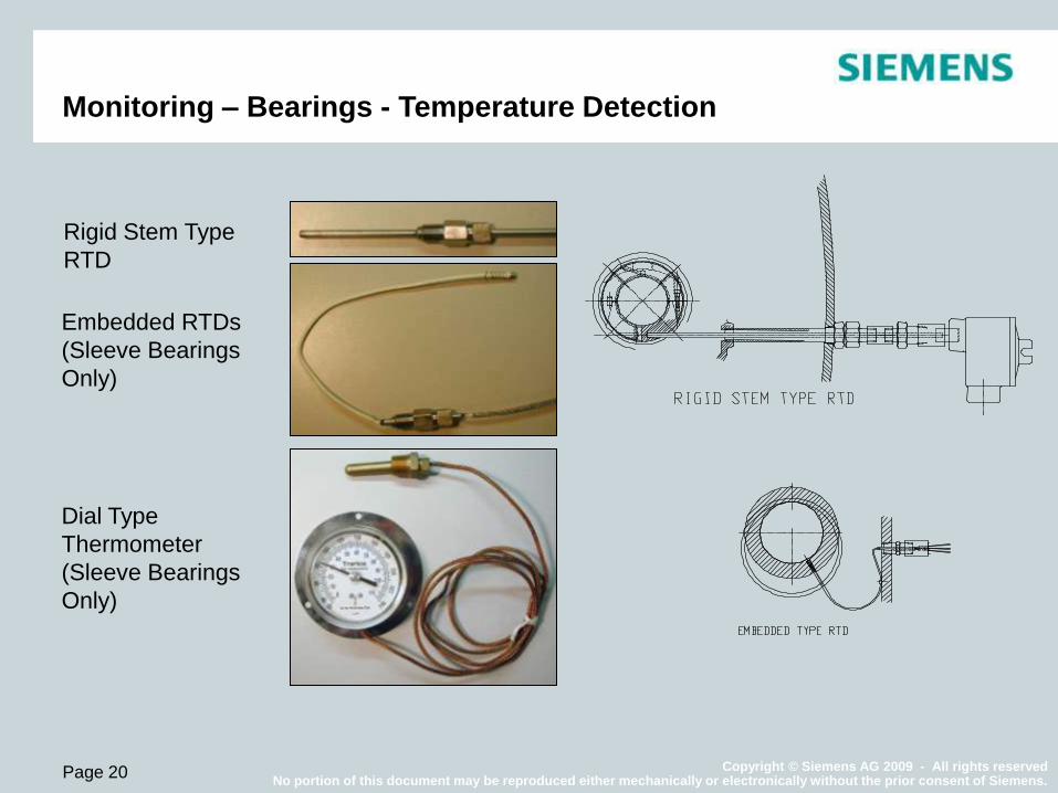
Monitoring – Bearings - Temperature Detection
Rigid Stem Type
RTD
Embedded RTDs
(Sleeve Bearings
Only)
Dial Type
Thermometer
(Sleeve Bearings
Only)
Copyright © Siemens AG 2009 - All rights reserved No portion of this document may be reproduced either mechanically or electronically without the prior consent of Siemens.
Page 21
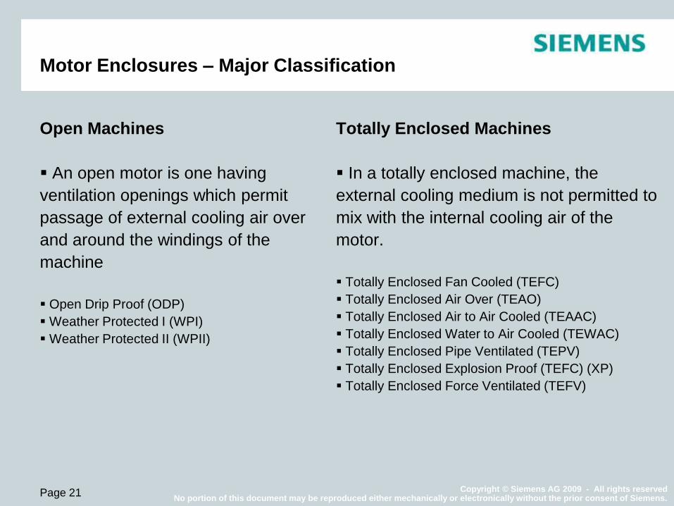
Motor Enclosures – Major Classification
Open Machines
An open motor is one having
ventilation openings which permit
passage of external cooling air over
and around the windings of the
machine
Open Drip Proof (ODP)
Weather Protected I (WPI)
Weather Protected II (WPII)
Totally Enclosed Machines
In a totally enclosed machine, the
external cooling medium is not permitted to
mix with the internal cooling air of the
motor.
Totally Enclosed Fan Cooled (TEFC)
Totally Enclosed Air Over (TEAO)
Totally Enclosed Air to Air Cooled (TEAAC)
Totally Enclosed Water to Air Cooled (TEWAC)
Totally Enclosed Pipe Ventilated (TEPV)
Totally Enclosed Explosion Proof (TEFC) (XP)
Totally Enclosed Force Ventilated (TEFV)

Copyright © Siemens AG 2009 - All rights reserved No portion of this document may be reproduced either mechanically or electronically without the prior consent of Siemens.
Page 22
Enclosures – Open
1
2 3
1
2
3
Air Inlet:
Three
90°
Bends
Air Outlet:
Three 90°
Bends
ODP/WPI
WPII

Copyright © Siemens AG 2009 - All rights reserved No portion of this document may be reproduced either mechanically or electronically without the prior consent of Siemens.
Page 23
Enclosures – Totally Enclosed
TEAAC
TEFC
TEWAC TEAO

Copyright © Siemens AG 2009 - All rights reserved No portion of this document may be reproduced either mechanically or electronically without the prior consent of Siemens.
Page 24
Enclosures – Degree of Protection
Environment dictates a minimum degree of protection.
Over-protection is as good as throwing money out the window.
FRAME
NEMA IEC/NEMA SIZE COST
ODP - Open Drip Proof IP12 SMALL LOW
WPI - Weather Protected Type I IP22 SMALL LOW
WPII - Weather Protected Type II IP24W SMALL MOD.
TEAAC - Totally Enclosed Air to Air Cooled IP 44-IP54 + 20% HIGHER
TEFC - Totally Enclosed Fin Cooled IP 44-IP54 + 30% HIGHER
TEWAC - Totally Enclosed Water-Air Cooled IP 44-IP54 SMALL HIGHER
TEFV - Totally Enclosed Forced Ventilated IP44 SMALL MOD.

Copyright © Siemens AG 2009 - All rights reserved No portion of this document may be reproduced either mechanically or electronically without the prior consent of Siemens.
Page 25
Monitoring – Accessories - Enclosures
Differential Pressure Switch
Gives indication of the condition of
air filters
Leak Detectors
Gives indication on the integrity
of water coolers
Copyright © Siemens AG 2009 - All rights reserved No portion of this document may be reproduced either mechanically or electronically without the prior consent of Siemens.
Page 26
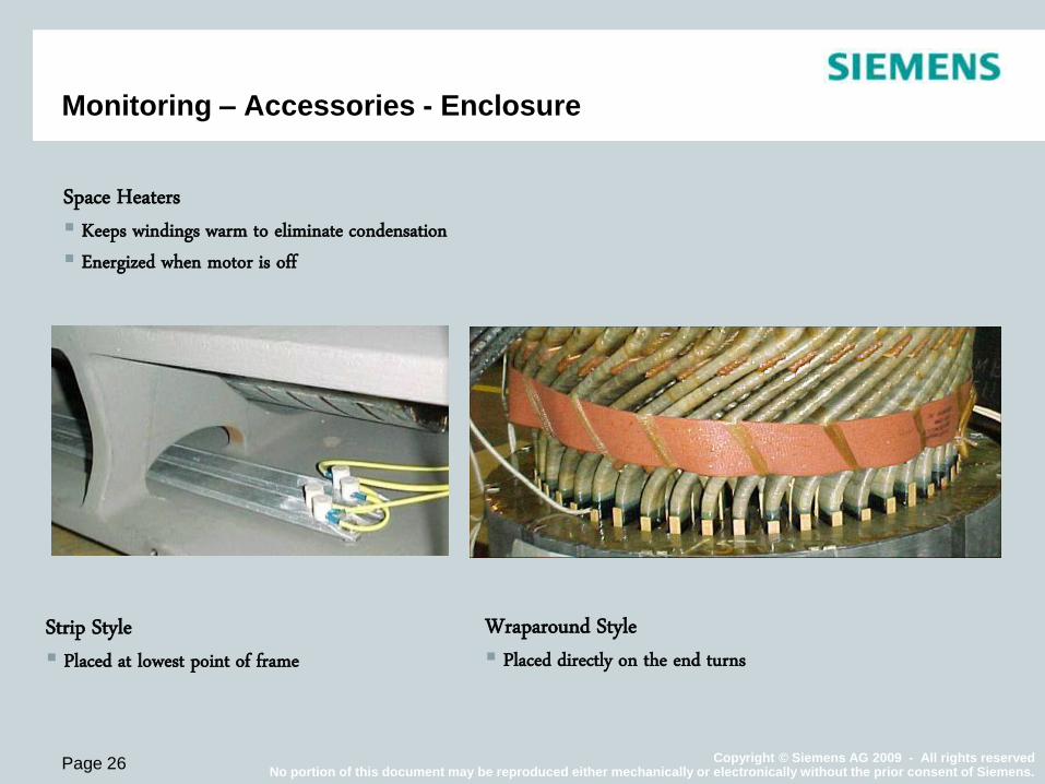
Monitoring – Accessories - Enclosure
Strip Style Placed at lowest point of frame
Wraparound Style Placed directly on the end turns
Space Heaters Keeps windings warm to eliminate condensation Energized when motor is off
Copyright © Siemens AG 2009 - All rights reserved No portion of this document may be reproduced either mechanically or electronically without the prior consent of Siemens.
Page 27
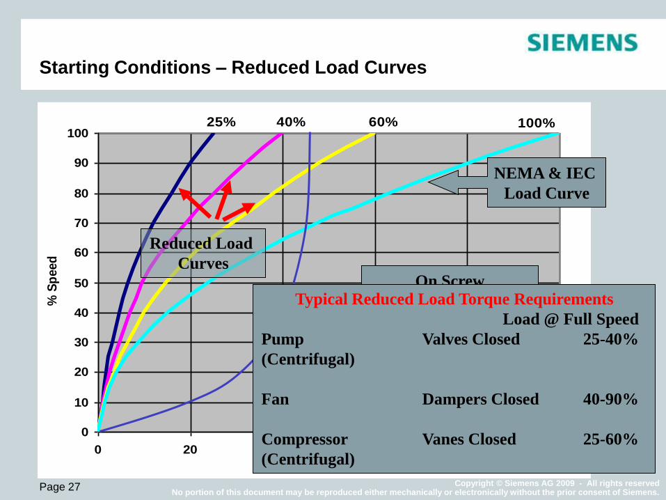
Starting Conditions – Reduced Load Curves
Starting
Condition
Torque at Full
Speed
Pump (centrifugal) Valve Closed 25 - 40%
Fan Dampers Closed 40 - 90%
Compressor
(centrifugal)
Vanes Closed 25 - 60%
0
10
20
30
40
50
60
70
80
90
100
0 20 40 60 80 100 % Torque
% S
peed
100% 60% 40% 25%
On Screw
Compressors
High Torque Required
at Low Speed, Will
Cause Trouble for a
Standard Motor at
Reduced Voltage
NEMA & IEC
Load Curve
Reduced Load
Curves
Typical Reduced Load Torque Requirements
Load @ Full Speed
Pump Valves Closed 25-40%
(Centrifugal)
Fan Dampers Closed 40-90%
Compressor Vanes Closed 25-60%
(Centrifugal)
Copyright © Siemens AG 2009 - All rights reserved No portion of this document may be reproduced either mechanically or electronically without the prior consent of Siemens.
Page 28
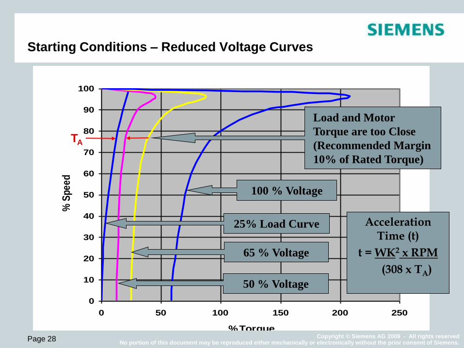
Starting Conditions – Reduced Voltage Curves
0
10
20
30
40
50
60
70
80
90
100
0 50 100 150 200 250
% Torque
% S
pe
ed
Load and Motor
Torque are too Close
(Recommended Margin
10% of Rated Torque)
65 % Voltage
100 % Voltage
50 % Voltage
25% Load Curve Acceleration Time (t)
t = WK2 x RPM
(308 x TA)
TA
Copyright © Siemens AG 2009 - All rights reserved No portion of this document may be reproduced either mechanically or electronically without the prior consent of Siemens.
Page 29
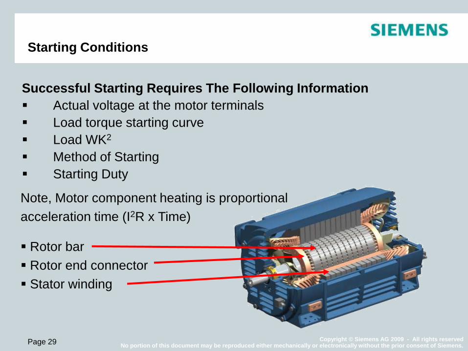
Starting Conditions
Successful Starting Requires The Following Information
Actual voltage at the motor terminals
Load torque starting curve
Load WK2
Method of Starting
Starting Duty
Note, Motor component heating is proportional
acceleration time (I2R x Time)
Rotor bar
Rotor end connector
Stator winding
Copyright © Siemens AG 2009 - All rights reserved No portion of this document may be reproduced either mechanically or electronically without the prior consent of Siemens.
Page 30
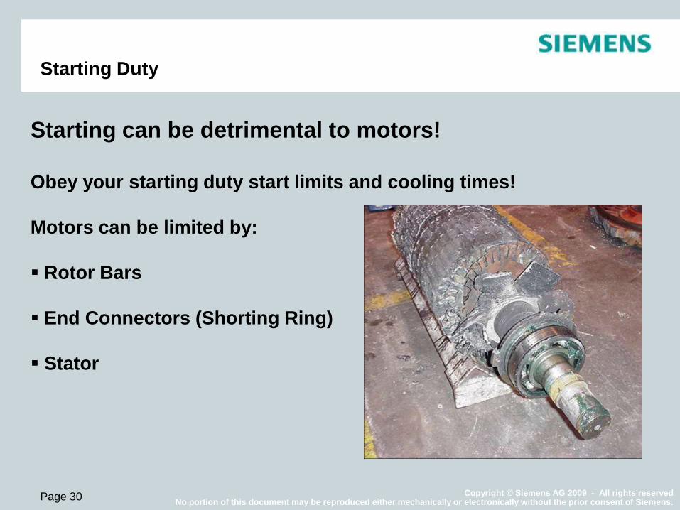
Starting Duty
Starting can be detrimental to motors!
Obey your starting duty start limits and cooling times!
Motors can be limited by:
Rotor Bars
End Connectors (Shorting Ring)
Stator

Copyright © Siemens AG 2009 - All rights reserved No portion of this document may be reproduced either mechanically or electronically without the prior consent of Siemens.
Page 31
Starting Duty - Number of starts and Cooling times
Number of starts, coasting to rest between starts:
2 starts with motor initially at ambient temperature (cold)
1 starts with motor at service factor operating temperature (hot)
Cooling period after either of above before making an additional
start:
100 minutes, motor running at service factor load
20 minutes, motor running, equipment unloaded
120 minutes, motor de-energized, coasted to rest and left idle
Copyright © Siemens AG 2009 - All rights reserved No portion of this document may be reproduced either mechanically or electronically without the prior consent of Siemens.
Page 32
0
50
100
150
200
250
300
350
400
0 2 4 6 8 10 12
Time (Min)
Tem
p (
C)
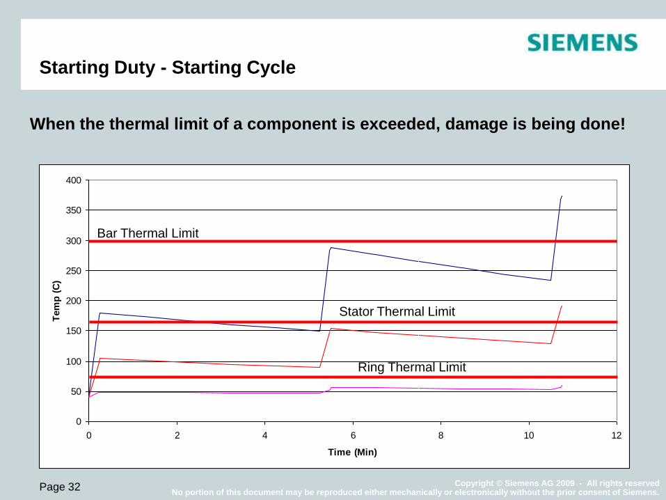
Starting Duty - Starting Cycle
When the thermal limit of a component is exceeded, damage is being done!
Bar Thermal Limit
Stator Thermal Limit
Ring Thermal Limit

Copyright © Siemens AG 2009 - All rights reserved No portion of this document may be reproduced either mechanically or electronically without the prior consent of Siemens.
Page 33
Mechanical Unbalance
Motor, Coupling Load
Magnetic Unbalance
(Rotating Magnetic Force
not opposed)
Stationary Magnetic Force
Vibration Stator/Rotor
Mechanical Problems
Looseness, Rubbing,
Bearing Problems
Sources of motor vibration
Copyright © Siemens AG 2009 - All rights reserved No portion of this document may be reproduced either mechanically or electronically without the prior consent of Siemens.
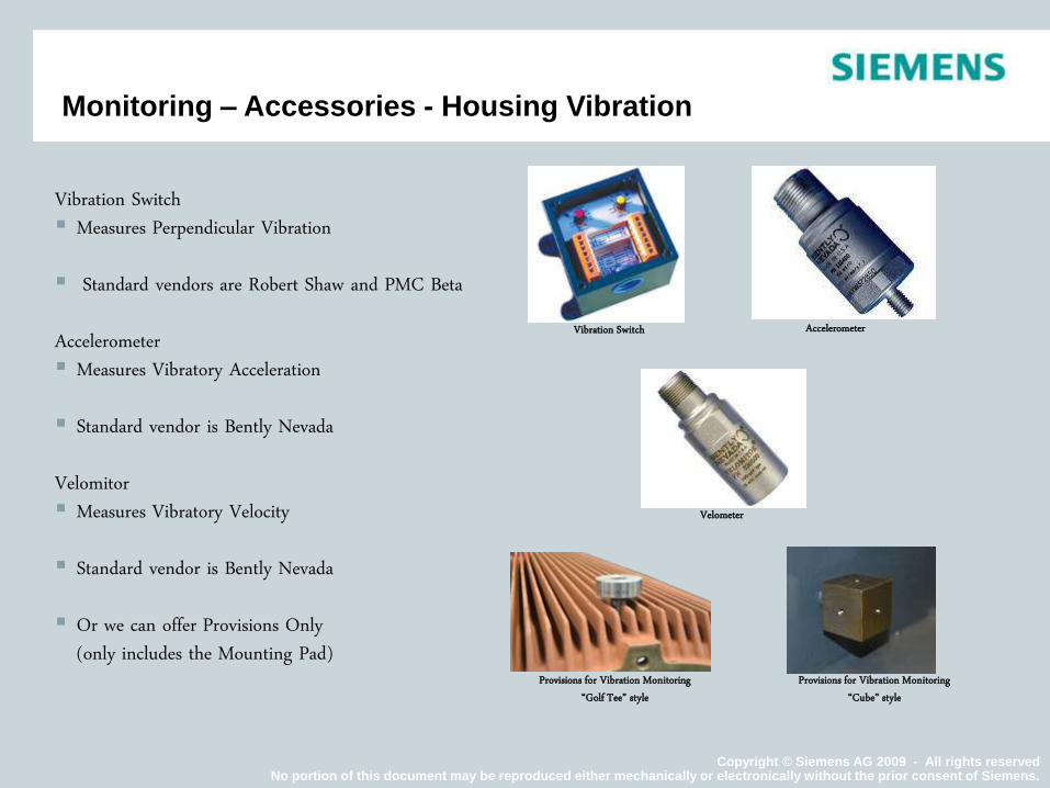
Vibration Switch Measures Perpendicular Vibration
Standard vendors are Robert Shaw and PMC Beta Accelerometer Measures Vibratory Acceleration
Standard vendor is Bently Nevada Velomitor Measures Vibratory Velocity
Standard vendor is Bently Nevada
Or we can offer Provisions Only
(only includes the Mounting Pad)
Vibration Switch Accelerometer
Velometer
Provisions for Vibration Monitoring “Golf Tee” style
Provisions for Vibration Monitoring “Cube” style
Monitoring – Accessories - Housing Vibration

Copyright © Siemens AG 2009 - All rights reserved No portion of this document may be reproduced either mechanically or electronically without the prior consent of Siemens.
Page 35
Monitoring – Accessories - Shaft Vibration
Typical shaft
vibration limit for
sleeve bearing
motors: ½ the
diametrical
clearance of the
sleeve bearing
Trip Limits May be
Increased by 10%
Over Alarm Limits
Industry Limits
(mils)

Copyright © Siemens AG 2009 - All rights reserved No portion of this document may be reproduced either mechanically or electronically without the prior consent of Siemens.
Page 36
Degradation of Bearings
Loosening of Rotor Bars
Coupling Degradation
Changes in Mounting Conditions (Deterioration of Grouted Base, Changes in
Alignment/Soft Foot, etc.)
Accumulation of Debris in the Oil Guards, between Rotor and Stator, etc.,
causing Rubs.
Accumulation of Debris in the Rotor Vents, End Rings or Fans causing
Unbalance.
Plugging up of Rotor Vents causing uneven Heating-Thermal Unbalance.
Vibration May Increase Over Time Due To:

Copyright © Siemens AG 2009 - All rights reserved No portion of this document may be reproduced either mechanically or electronically without the prior consent of Siemens.
Page 37
Monitoring
A good idea… but how far do you
go?
How critical is the application?
What is the cost of downtime?
How useful is the information?
What is the cost of monitoring?
Copyright © Siemens AG 2009 - All rights reserved No portion of this document may be reproduced either mechanically or electronically without the prior consent of Siemens.
Page 38
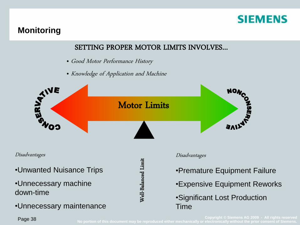
Monitoring
SETTING PROPER MOTOR LIMITS INVOLVES… • Good Motor Performance History • Knowledge of Application and Machine
Motor Limits
Well
-Balan
ced Li
mit Disadvantages
•Unwanted Nuisance Trips
•Unnecessary machine
down-time
•Unnecessary maintenance
Disadvantages
•Premature Equipment Failure
•Expensive Equipment Reworks
•Significant Lost Production
Time

Copyright © Siemens AG 2009 - All rights reserved No portion of this document may be reproduced either mechanically or electronically without the prior consent of Siemens.
Questions?