Embed Size (px)
Citation preview
REM
EHA G
ILLES BIO
MASS R
ANG
E
Biomass RangeWood Chip & Pellet Boilers
A practical guide to choices of fuel,storage, fuel transport and biomassboiler installation up to 2000 kW.
OUTPUTS: 12.5-2000 kWLarger outputs available on request.
2
Remeha - Providing the mosteffective boiler technology Remeha is part of the De Dietrich Remeha Group - one of the top five boiler manufacturers in the Europeancommercial and domestic heating market.The Remeha brand is renowned for quality, reliability and efficiency. We are committed to increasing the alreadyhigh performance standards of our boilersthrough an ongoing programme oftechnological innovation. De DietrichRemeha Group and Baxi Group haveannounced the creation of BDR Thermea, anew world class company in innovativeclimate and hot water solutions andservices. The complementary geographicprofile of De Dietrich Remeha Group andBaxi Group will put the new group in aleading position in all Western EuropeanCountries.
With more than 35 years experience in thedevelopment and production of condensingboilers, Remeha is at the forefront of thisfield. We are also a leading supplier ofbiomass boilers and offer a wide range of
commercial atmospheric and forceddraught boilers. In addition, Remeha’s rangeof domestic boilers includes some of thelightest and most compact and efficientproducts on the market.
Global climate change is one of the mostpressing issues of our time and, in responseto this, Remeha offers a pioneering carbonoffsetting programme, in partnership withJ.P. Morgan ClimateCare. Having offset thecarbon emissions from its own UKoperations, Remeha can provide theopportunity for its customers to do thesame.
Carbon offsets can be arranged against thepredicted carbon emissions for each newRemeha boiler so that a near neutral carbonbalance is created. All funds donated forcarbon offsets are used to finance carbonreducing projects in poorer countries.
For more information on Remeha productsand the carbon offsetting programme,please call: 0118 978 3434.
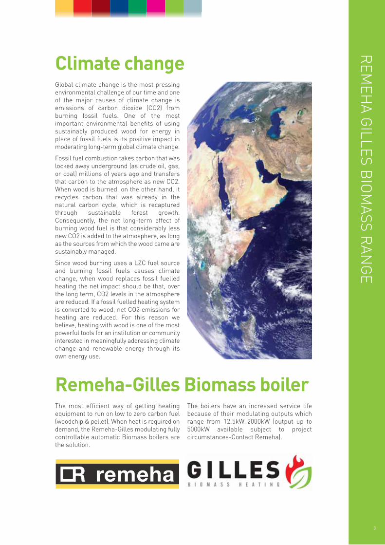
Global climate change is the most pressingenvironmental challenge of our time and oneof the major causes of climate change isemissions of carbon dioxide (CO2) fromburning fossil fuels. One of the mostimportant environmental benefits of usingsustainably produced wood for energy inplace of fossil fuels is its positive impact inmoderating long-term global climate change.
Fossil fuel combustion takes carbon that waslocked away underground (as crude oil, gas,or coal) millions of years ago and transfersthat carbon to the atmosphere as new CO2.When wood is burned, on the other hand, itrecycles carbon that was already in thenatural carbon cycle, which is recapturedthrough sustainable forest growth.Consequently, the net long-term effect ofburning wood fuel is that considerably lessnew CO2 is added to the atmosphere, as longas the sources from which the wood came aresustainably managed.
Since wood burning uses a LZC fuel sourceand burning fossil fuels causes climatechange, when wood replaces fossil fuelledheating the net impact should be that, overthe long term, CO2 levels in the atmosphereare reduced. If a fossil fuelled heating systemis converted to wood, net CO2 emissions forheating are reduced. For this reason webelieve, heating with wood is one of the mostpowerful tools for an institution or communityinterested in meaningfully addressing climatechange and renewable energy through itsown energy use.
The most efficient way of getting heatingequipment to run on low to zero carbon fuel(woodchip & pellet). When heat is required ondemand, the Remeha-Gilles modulating fullycontrollable automatic Biomass boilers arethe solution.
The boilers have an increased service lifebecause of their modulating outputs whichrange from 12.5kW-2000kW (output up to5000kW available subject to projectcircumstances-Contact Remeha).
REM
EHA G
ILLES BIO
MASS R
ANG
E
3
Remeha-Gilles Biomass boiler
Climate change
4
Wood pellets vs wood chips• Pellets flow freely whereas chips do not.
• Pellets are a more dense form of fuel than chips therefore take less storage space per kw/hr.
• Pellets are generally more expensive per kw/hr than chips.
• Chips are more environmentally friendly than pellets as they take less energy to create.
• A wood chip boiler can burn pellets whereas a pellet boiler can’t burn chips.
In brief summaryIt can be seen that wood chips are moreenvironmentally friendly but take up morestorage space.
At the time of writing (Summer 2010) chipsare about 60% of the cost per kw/hr ofNatural Gas and pellets are about the sameas Natural Gas, therefore chips do have thepossibility of giving a payback as well. Pelletsare about 50% the cost of Gas Oil per kw/hr.
But if fuel storage space, on site labour or alocal supply of chips are unavailable, it isevident that pellets will give a significantcarbon reduction over traditionalheating fuels.
Wood fuel storageConsideration now needs to be given to thetype of fuel store suitable for the differentfuels as each has a different requirement.There is however one overridingconsideration to bear in mind for both fuels:it is easier to move the heating systemwater than wood fuel, so try and keep thefuel store as close to the wood boiler aspossible, the simpler the fuel route thebetter!!
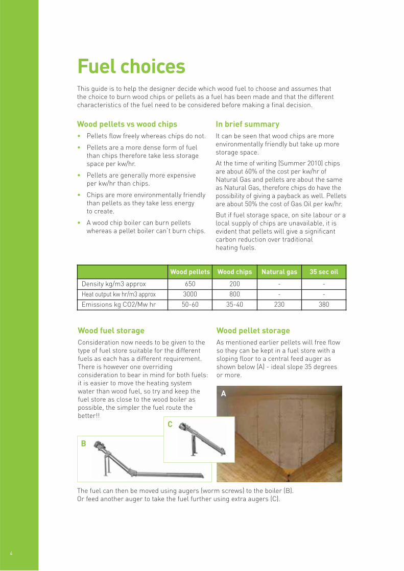
Wood pellet storageAs mentioned earlier pellets will free flowso they can be kept in a fuel store with asloping floor to a central feed auger asshown below (A) - ideal slope 35 degreesor more.
A
B
C
The fuel can then be moved using augers (worm screws) to the boiler (B).Or feed another auger to take the fuel further using extra augers (C).
Fuel choices
Wood pellets Wood chips Natural gas 35 sec oil
Density kg/m3 approx 650 200 - -
Heat output kw hr/m3 approx 3000 800 - -
Emissions kg CO2/Mw hr 50-60 35-40 230 380
This guide is to help the designer decide which wood fuel to choose and assumes that the choice to burn wood chips or pellets as a fuel has been made and that the differentcharacteristics of the fuel need to be considered before making a final decision.
REM
EHA G
ILLES BIO
MASS R
ANG
E
5
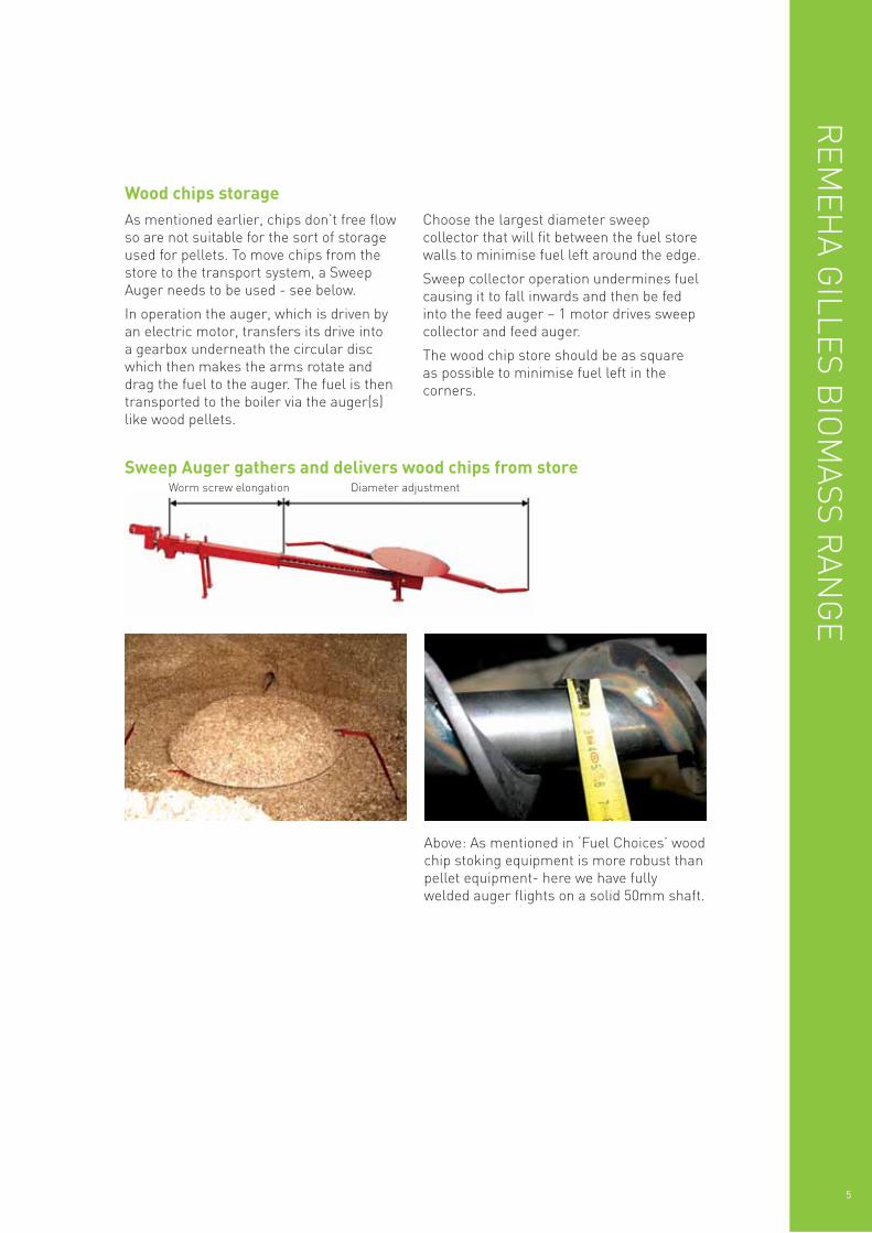
Sweep Auger gathers and delivers wood chips from store
As mentioned earlier, chips don’t free flowso are not suitable for the sort of storageused for pellets. To move chips from thestore to the transport system, a SweepAuger needs to be used - see below.
In operation the auger, which is driven byan electric motor, transfers its drive into a gearbox underneath the circular discwhich then makes the arms rotate and drag the fuel to the auger. The fuel is thentransported to the boiler via the auger(s)like wood pellets.
Choose the largest diameter sweepcollector that will fit between the fuel storewalls to minimise fuel left around the edge.
Sweep collector operation undermines fuelcausing it to fall inwards and then be fedinto the feed auger – 1 motor drives sweepcollector and feed auger.
The wood chip store should be as square as possible to minimise fuel left in thecorners.
Wood chips storage
Above: As mentioned in ‘Fuel Choices’ woodchip stoking equipment is more robust thanpellet equipment- here we have fullywelded auger flights on a solid 50mm shaft.
Worm screw elongation Diameter adjustment
6
Pellet heatingHPK-RA 12.5-150
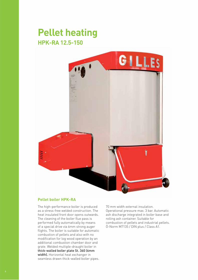
The high-performance boiler is produced as a stress-free welded construction. Theheat insulated front door opens outwards.The cleaning of the boiler flue pass isperformed fully automatically by means of a special drive via 6mm strong augerflights. The boiler is suitable for automaticcombustion of pellets and also with nomodification for log wood operation by anadditional combustion chamber door andgrate. Welded multiple-draught boiler inthick-walled boiler plate St. 360 (6mmwidth). Horizontal heat exchanger inseamless drawn thick-walled boiler pipes.
70 mm width external insulation.Operational pressure max. 3 bar. Automaticash discharge integrated in boiler base androlling ash container. Suitable forcombustion of pellets and industrial pellets.Ö-Norm M7135 / DIN plus / Class A1.
Pellet boiler HPK-RA
REM
EHA G
ILLES BIO
MASS R
ANG
E
7
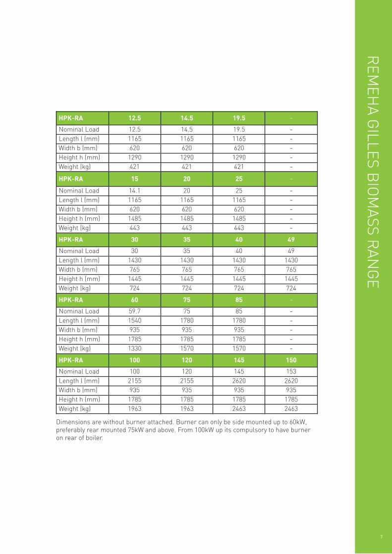
Dimensions are without burner attached. Burner can only be side mounted up to 60kW,preferably rear mounted 75kW and above. From 100kW up its compulsory to have burneron rear of boiler.
HPK-RA 12.5 14.5 19.5 -Nominal Load 12.5 14.5 19.5 -Length l (mm) 1165 1165 1165 -Width b (mm) 620 620 620 -Height h (mm) 1290 1290 1290 -Weight (kg) 421 421 421 -HPK-RA 15 20 25 -Nominal Load 14.1 20 25 -Length l (mm) 1165 1165 1165 -Width b (mm) 620 620 620 -Height h (mm) 1485 1485 1485 -Weight (kg) 443 443 443 -HPK-RA 30 35 40 49
Nominal Load 30 35 40 49Length l (mm) 1430 1430 1430 1430Width b (mm) 765 765 765 765Height h (mm) 1445 1445 1445 1445Weight (kg) 724 724 724 724
HPK-RA 60 75 85 -Nominal Load 59.7 75 85 -Length l (mm) 1540 1780 1780 -Width b (mm) 935 935 935 -Height h (mm) 1785 1785 1785 -Weight (kg) 1330 1570 1570 -HPK-RA 100 120 145 150
Nominal Load 100 120 145 153Length l (mm) 2155 2155 2620 2620Width b (mm) 935 935 935 935Height h (mm) 1785 1785 1785 1785Weight (kg) 1963 1963 2463 2463
HPK-RA 15-60
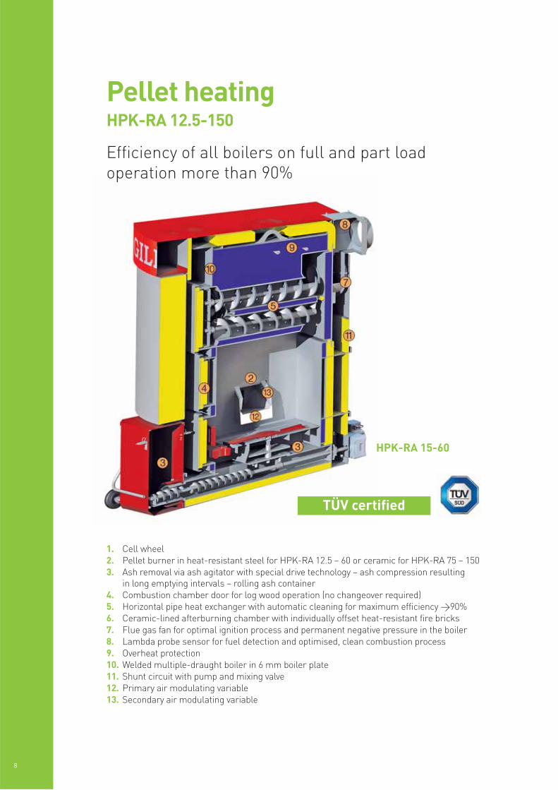
Efficiency of all boilers on full and part loadoperation more than 90%
1. Cell wheel2. Pellet burner in heat-resistant steel for HPK-RA 12.5 – 60 or ceramic for HPK-RA 75 – 1503. Ash removal via ash agitator with special drive technology – ash compression resulting
in long emptying intervals – rolling ash container4. Combustion chamber door for log wood operation (no changeover required)5. Horizontal pipe heat exchanger with automatic cleaning for maximum efficiency >90%6. Ceramic-lined afterburning chamber with individually offset heat-resistant fire bricks7. Flue gas fan for optimal ignition process and permanent negative pressure in the boiler8. Lambda probe sensor for fuel detection and optimised, clean combustion process9. Overheat protection10. Welded multiple-draught boiler in 6 mm boiler plate11. Shunt circuit with pump and mixing valve12. Primary air modulating variable13. Secondary air modulating variable
8
Pellet heatingHPK-RA 12.5-150
TÜV certified
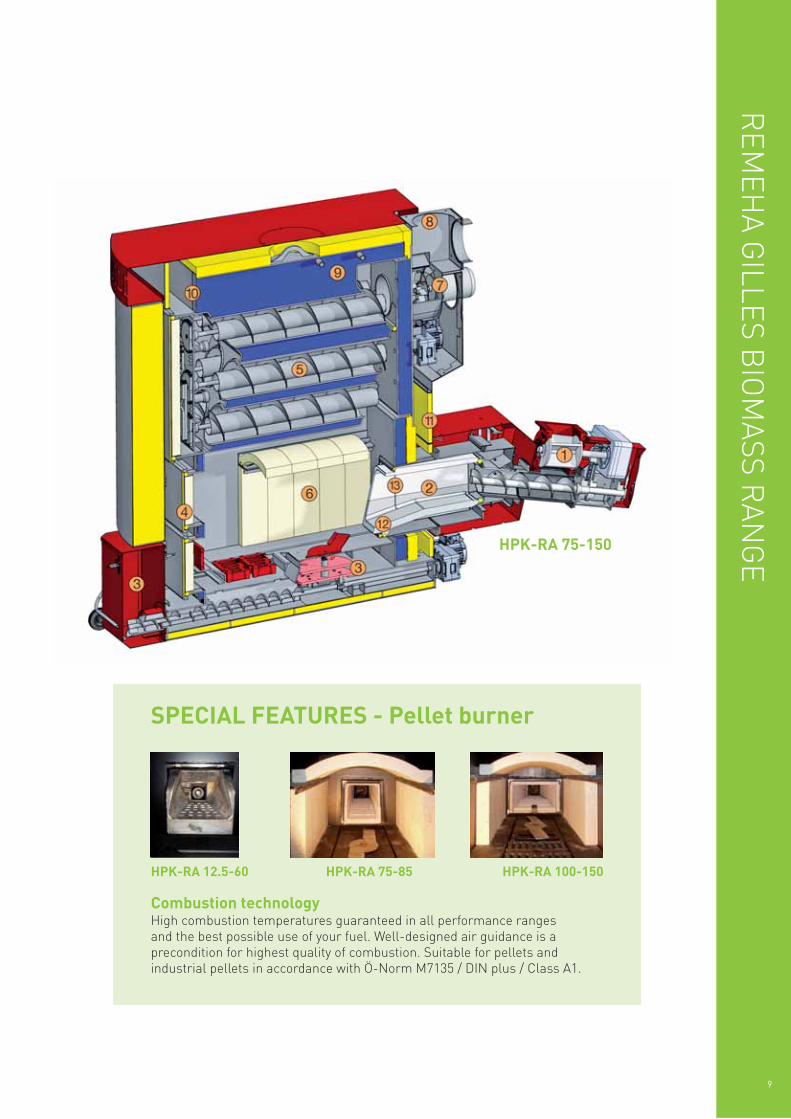
Combustion technologyHigh combustion temperatures guaranteed in all performance ranges and the best possible use of your fuel. Well-designed air guidance is aprecondition for highest quality of combustion. Suitable for pellets andindustrial pellets in accordance with Ö-Norm M7135 / DIN plus / Class A1.
HPK-RA 12.5-60 HPK-RA 75-85 HPK-RA 100-150
SPECIAL FEATURES - Pellet burner
HPK-RA 75-150
REM
EHA G
ILLES BIO
MASS R
ANG
E
9
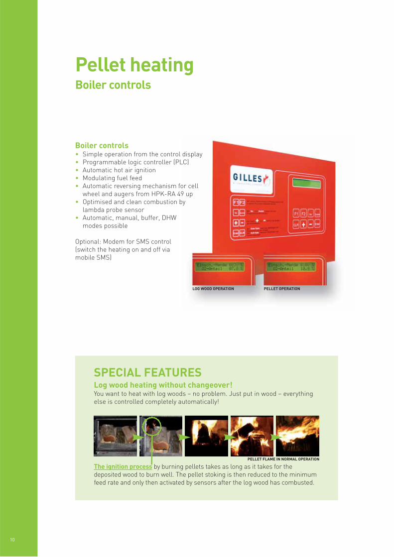
Boiler controls• Simple operation from the control display• Programmable logic controller (PLC)• Automatic hot air ignition• Modulating fuel feed• Automatic reversing mechanism for cell
wheel and augers from HPK-RA 49 up• Optimised and clean combustion by
lambda probe sensor• Automatic, manual, buffer, DHW
modes possible
Optional: Modem for SMS control(switch the heating on and off viamobile SMS)
The ignition process by burning pellets takes as long as it takes for thedeposited wood to burn well. The pellet stoking is then reduced to the minimumfeed rate and only then activated by sensors after the log wood has combusted.
10
Pellet heatingBoiler controls
SPECIAL FEATURESLog wood heating without changeover!You want to heat with log woods – no problem. Just put in wood – everythingelse is controlled completely automatically!
LOG WOOD OPERATION PELLET OPERATION
PELLET FLAME IN NORMAL OPERATION
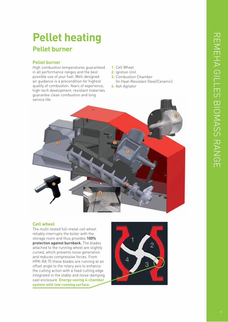
Cell wheelThe multi-tested full-metal cell wheelreliably interrupts the boiler with thestorage room and thus provides 100%protection against burnback. The bladesattached to the running wheel are slightlycurved, which prevents noise generationand reduces compressive forces. FromHPK-RA 75 these blades are running at anoffset angle to the rotary axis to enhancethe cutting action with a fixed cutting edgeintegrated in the stable and noise-dampingcast enclosure. Energy-saving 4-chambersystem with low running surface.
Pellet heatingPellet burner
REM
EHA G
ILLES BIO
MASS R
ANG
E
11
Pellet burnerHigh combustion temperatures guaranteedin all performance ranges and the bestpossible use of your fuel. Well-designed air guidance is a precondition for highestquality of combustion. Years of experience,high-tech development, resistant materialsguarantee clean combustion and longservice life.
1. Cell Wheel2. Ignition Unit3. Combustion Chamber
(In Heat-Resistant Steel/Ceramic)4. Ash Agitator
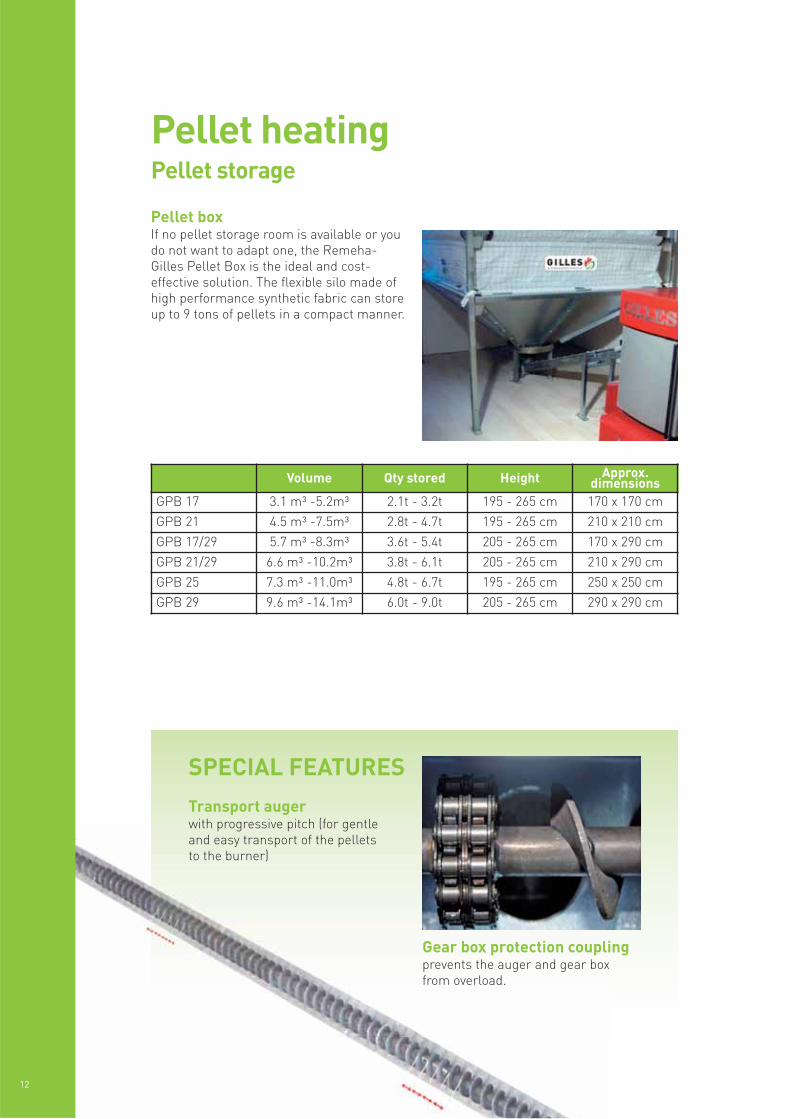
Pellet boxIf no pellet storage room is available or youdo not want to adapt one, the Remeha-Gilles Pellet Box is the ideal and cost-effective solution. The flexible silo made ofhigh performance synthetic fabric can storeup to 9 tons of pellets in a compact manner.
12
Pellet heatingPellet storage
Volume Qty stored Height Approx.dimensions
GPB 17 3.1 m³ -5.2m³ 2.1t - 3.2t 195 - 265 cm 170 x 170 cm
GPB 21 4.5 m³ -7.5m³ 2.8t - 4.7t 195 - 265 cm 210 x 210 cm
GPB 17/29 5.7 m³ -8.3m³ 3.6t - 5.4t 205 - 265 cm 170 x 290 cm
GPB 21/29 6.6 m³ -10.2m³ 3.8t - 6.1t 205 - 265 cm 210 x 290 cm
GPB 25 7.3 m³ -11.0m³ 4.8t - 6.7t 195 - 265 cm 250 x 250 cm
GPB 29 9.6 m³ -14.1m³ 6.0t - 9.0t 205 - 265 cm 290 x 290 cm
Gear box protection couplingprevents the auger and gear boxfrom overload.
SPECIAL FEATURESTransport augerwith progressive pitch (for gentleand easy transport of the pelletsto the burner)
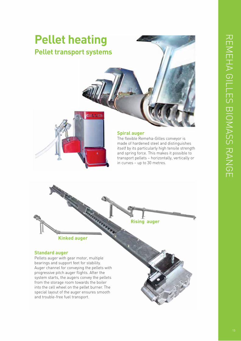
Spiral augerThe flexible Remeha-Gilles conveyor ismade of hardened steel and distinguishesitself by its particularly high tensile strengthand spring force. This makes it possible totransport pellets – horizontally, vertically orin curves – up to 30 metres.
Standard augerPellets auger with gear motor, multiplebearings and support feet for stability. Auger channel for conveying the pellets withprogressive pitch auger flights. After thesystem starts, the augers convey the pelletsfrom the storage room towards the boilerinto the cell wheel on the pellet burner. Thespecial layout of the auger ensures smoothand trouble-free fuel transport.
Rising auger
Kinked auger
REM
EHA G
ILLES BIO
MASS R
ANG
E
13
Pellet heatingPellet transport systems
14
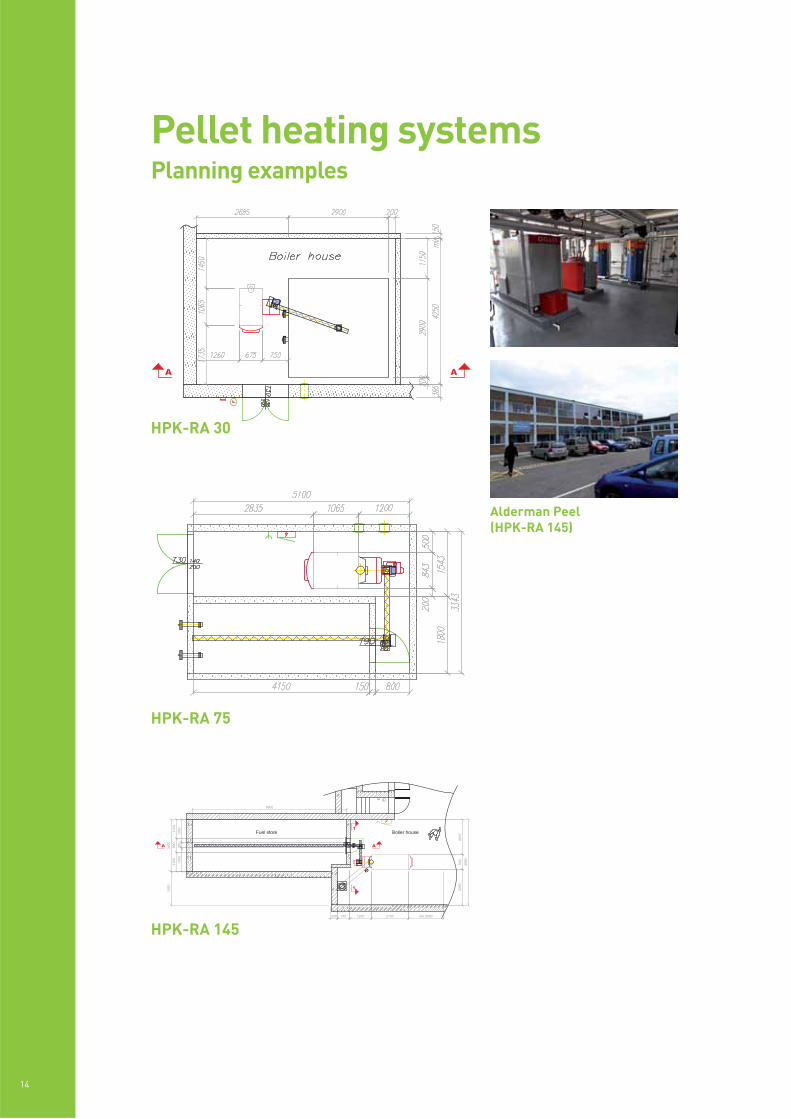
Pellet heating systemsPlanning examples
Alderman Peel(HPK-RA 145)
HPK-RA 75
HPK-RA 145
HPK-RA 30
REM
EHA G
ILLES BIO
MASS R
ANG
E
15
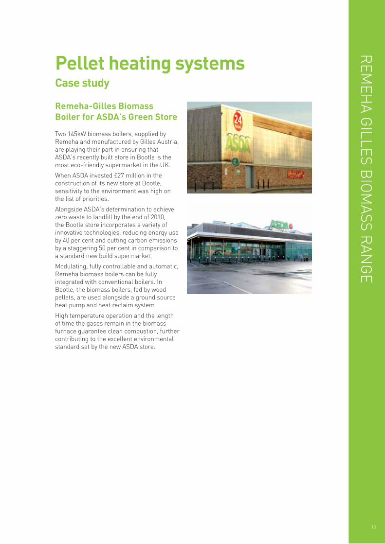
Pellet heating systemsCase study
Two 145kW biomass boilers, supplied byRemeha and manufactured by Gilles Austria,are playing their part in ensuring thatASDA’s recently built store in Bootle is themost eco-friendly supermarket in the UK.
When ASDA invested £27 million in theconstruction of its new store at Bootle,sensitivity to the environment was high onthe list of priorities.
Alongside ASDA’s determination to achievezero waste to landfill by the end of 2010, the Bootle store incorporates a variety ofinnovative technologies, reducing energy useby 40 per cent and cutting carbon emissionsby a staggering 50 per cent in comparison toa standard new build supermarket.
Modulating, fully controllable and automatic,Remeha biomass boilers can be fullyintegrated with conventional boilers. InBootle, the biomass boilers, fed by woodpellets, are used alongside a ground sourceheat pump and heat reclaim system.
High temperature operation and the lengthof time the gases remain in the biomassfurnace guarantee clean combustion, furthercontributing to the excellent environmentalstandard set by the new ASDA store.
Remeha-Gilles BiomassBoiler for ASDA’s Green Store
16
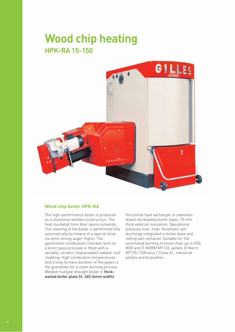
Wood chip heatingHPK-RA 15-150
The high-performance boiler is produced as a stressfree welded construction. Theheat insulated front door opens outwards.The cleaning of the boiler is performed fullyautomatically by means of a special drivevia 6mm strong auger flights. Thegasification combustion chamber built on a direct pass principle is fitted with avariable, ceramic (replaceable) radiator roofcladding. High combustion temperaturesand a long furnace duration of the gases isthe guarantee for a clean burning process.Welded multiple-draught boiler in thick-walled boiler plate St. 360 (6mm width).
Horizontal heat exchanger in seamlessdrawn thickwalled boiler pipes. 70 mmthick external insulation. Operationalpressure max. 3 bar. Automatic ashdischarge integrated in boiler base androlling ash container. Suitable for theautomated burning of wood chips up to G50,W30 and Ö-NORM M7133, pellets Ö-NormM7135 / DIN plus / Class A1, industrialpellets and briquettes.
Wood chip boiler HPK-RA
REM
EHA G
ILLES BIO
MASS R
ANG
E
17
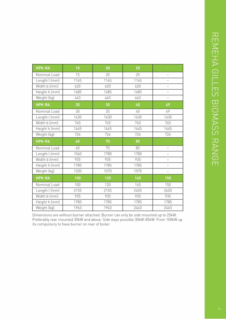
Dimensions are without burner attached. Burner can only be side mounted up to 25kW.Preferably rear mounted 30kW and above. Side ways possible 30kW-85kW. From 100kW upits compulsory to have burner on rear of boiler.
HPK-RA 15 20 25 -Nominal Load 15 20 25 -Length l (mm) 1165 1165 1165 -Width b (mm) 620 620 620 -Height h (mm) 1485 1485 1485 -Weight (kg) 443 443 443 -HPK-RA 30 35 40 49
Nominal Load 30 35 40 49
Length l (mm) 1430 1430 1430 1430
Width b (mm) 765 765 765 765
Height h (mm) 1445 1445 1445 1445
Weight (kg) 724 724 724 724
HPK-RA 60 75 85 -Nominal Load 60 75 85 -Length l (mm) 1540 1780 1780 -Width b (mm) 935 935 935 -Height h (mm) 1785 1785 1785 -Weight (kg) 1330 1570 1570 -HPK-RA 100 120 145 150
Nominal Load 100 120 145 150
Length l (mm) 2155 2155 2620 2620
Width b (mm) 935 935 935 935
Height h (mm) 1785 1785 1785 1785
Weight (kg) 1963 1963 2463 2463
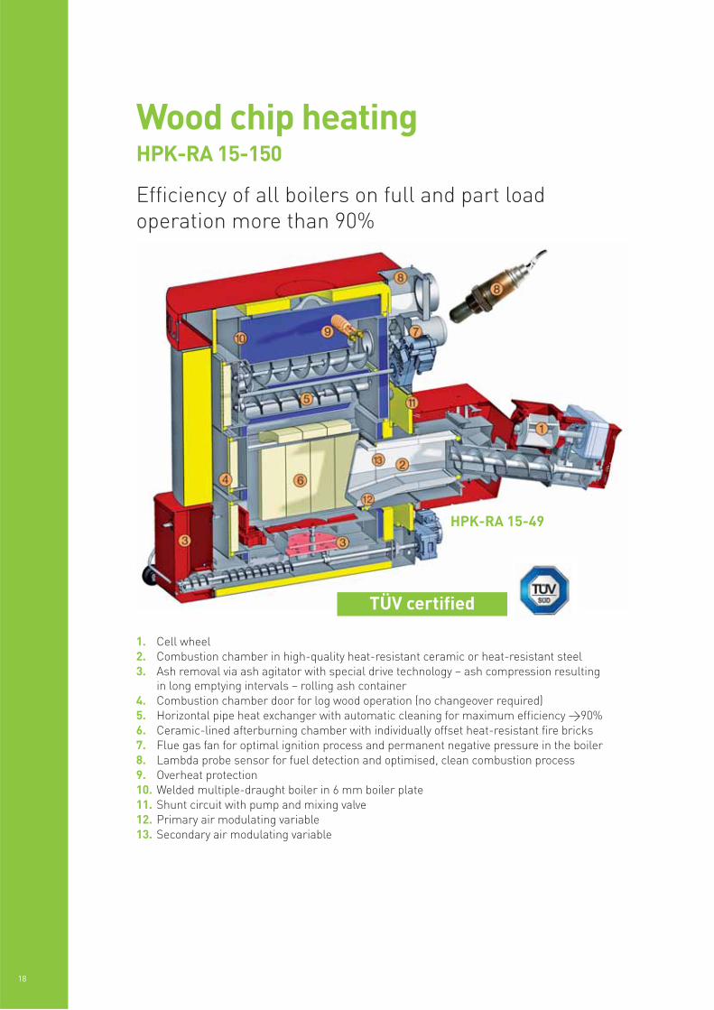
HPK-RA 15-49
1. Cell wheel2. Combustion chamber in high-quality heat-resistant ceramic or heat-resistant steel3. Ash removal via ash agitator with special drive technology – ash compression resulting
in long emptying intervals – rolling ash container4. Combustion chamber door for log wood operation (no changeover required)5. Horizontal pipe heat exchanger with automatic cleaning for maximum efficiency >90%6. Ceramic-lined afterburning chamber with individually offset heat-resistant fire bricks7. Flue gas fan for optimal ignition process and permanent negative pressure in the boiler8. Lambda probe sensor for fuel detection and optimised, clean combustion process9. Overheat protection10. Welded multiple-draught boiler in 6 mm boiler plate11. Shunt circuit with pump and mixing valve12. Primary air modulating variable13. Secondary air modulating variable
18
Wood chip heatingHPK-RA 15-150
Efficiency of all boilers on full and part loadoperation more than 90%
TÜV certified
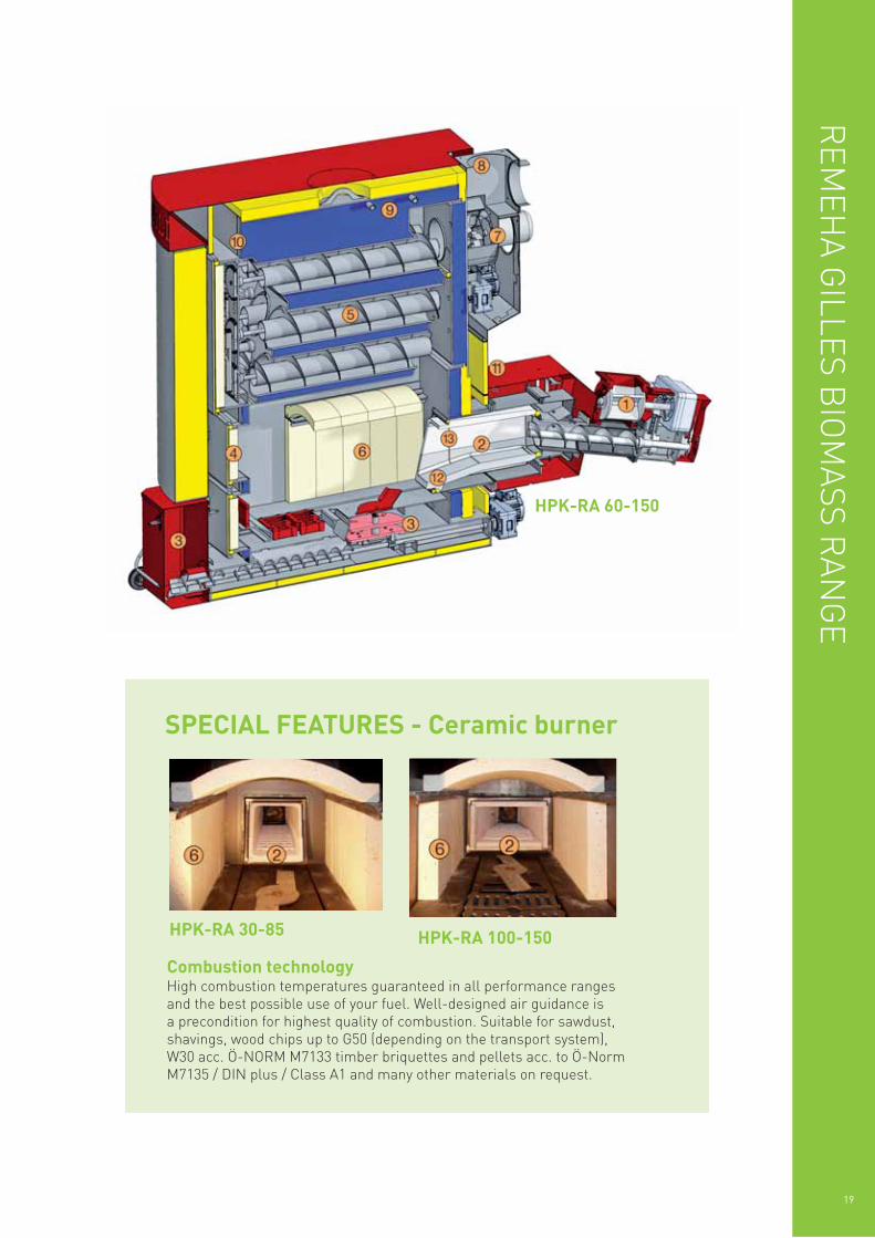
HPK-RA 60-150
REM
EHA G
ILLES BIO
MASS R
ANG
E
19
SPECIAL FEATURES - Ceramic burner
HPK-RA 30-85 HPK-RA 100-150
Combustion technologyHigh combustion temperatures guaranteed in all performance ranges and the best possible use of your fuel. Well-designed air guidance is a precondition for highest quality of combustion. Suitable for sawdust,shavings, wood chips up to G50 (depending on the transport system), W30 acc. Ö-NORM M7133 timber briquettes and pellets acc. to Ö-NormM7135 / DIN plus / Class A1 and many other materials on request.
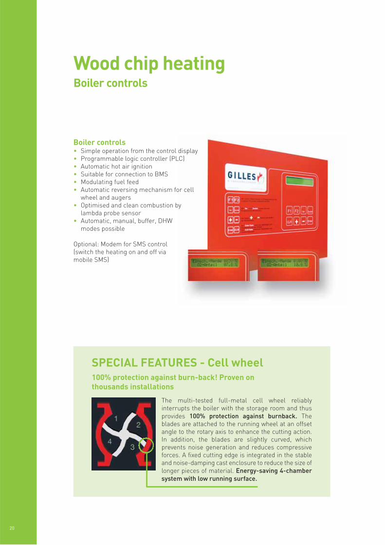
The multi-tested full-metal cell wheel reliablyinterrupts the boiler with the storage room and thusprovides 100% protection against burnback. Theblades are attached to the running wheel at an offsetangle to the rotary axis to enhance the cutting action.In addition, the blades are slightly curved, whichprevents noise generation and reduces compressiveforces. A fixed cutting edge is integrated in the stableand noise-damping cast enclosure to reduce the size oflonger pieces of material. Energy-saving 4-chambersystem with low running surface.
100% protection against burn-back! Proven onthousands installations
20
Wood chip heatingBoiler controls
Boiler controls• Simple operation from the control display• Programmable logic controller (PLC)• Automatic hot air ignition• Suitable for connection to BMS• Modulating fuel feed• Automatic reversing mechanism for cell
wheel and augers• Optimised and clean combustion by
lambda probe sensor• Automatic, manual, buffer, DHW
modes possible
Optional: Modem for SMS control(switch the heating on and off viamobile SMS)
SPECIAL FEATURES - Cell wheel
1. Spur gear motor (maintenance free due to oil immersed helical gears)2. Connection point sprinkle valve3. Ripping hook4. Start-up relief by vibration cushioning5. Ignition unit6. Ceramic combustion chamber7. Auger channel8. Transport auger9. Cell wheel
REM
EHA G
ILLES BIO
MASS R
ANG
E
21
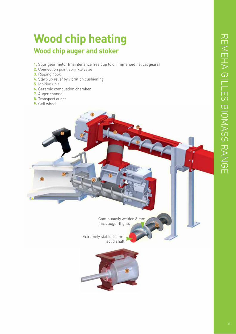
Wood chip heatingWood chip auger and stoker
Extremely stable 50 mmsolid shaft
Continuously welded 8 mmthick auger flights
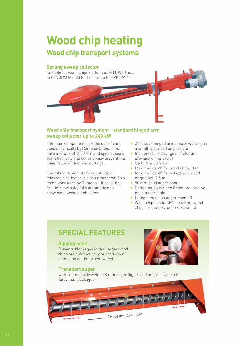
The main components are the spur gearsused specifically by Remeha-Gilles. Theyhave a torque of 5000 Nm and special sealsthat effectively and continuously prevent thepenetration of dust and cuttings.
The robust design of the double-armtelescopic collector is also unmatched. Thistechnology used by Remeha-Gilles is thefirst to allow safe, fully automatic andconvenient wood combustion.
• 2 massive hinged arms make working ina small space radius possible
• Incl. pressure disc, gear motor andpre-tensioning device
• Up to 6 m diameter• Max. fuel depth for wood chips: 8 m• Max. fuel depth for pellets and wood
briquettes: 2.5 m• 50 mm solid auger shaft• Continuously welded 8 mm progressive
pitch auger flights• Large dimension auger channel• Wood chips up to G50, industrial wood
chips, briquettes, pellets, sawdust
22
Wood chip heatingWood chip transport systems
Sprung sweep collectorSuitable for wood chips up to max. G30, W30 acc.to Ö-NORM M7133 for boilers up to HPK-RA 60
Wood chip transport system - standard hinged armsweep collector up to 240 kW
Conveying direction
Transport augerwith continuously welded 8 mm auger flights and progressive pitch(prevents blockages)
Ripping hookPrevents blockages in that larger woodchips are automatically pushed downto then be cut in the cell wheel.
SPECIAL FEATURES
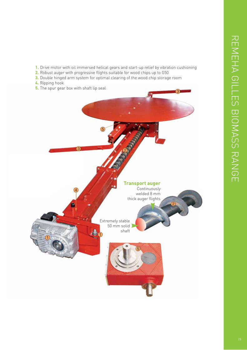
1. Drive motor with oil immersed helical gears and start-up relief by vibration cushioning2. Robust auger with progressive flights suitable for wood chips up to G503. Double hinged arm system for optimal clearing of the wood chip storage room4. Ripping hook5. The spur gear box with shaft lip seal
REM
EHA G
ILLES BIO
MASS R
ANG
E
23
Extremely stable50 mm solid
shaft
Transport augerContinuouslywelded 8 mm
thick auger flights
24
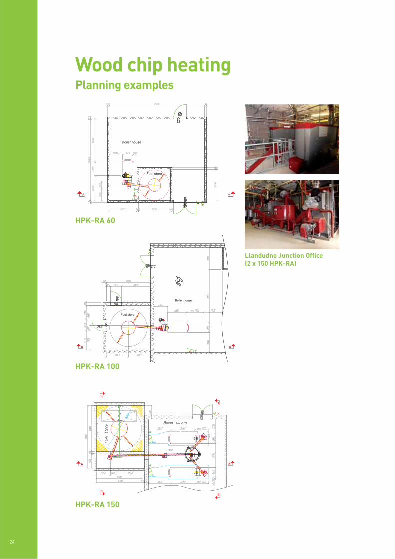
Wood chip heatingPlanning examples
Llandudno Junction Office(2 x 150 HPK-RA)
HPK-RA 100
HPK-RA 150
HPK-RA 60
REM
EHA G
ILLES BIO
MASS R
ANG
E
25
Wood chip heatingCase study
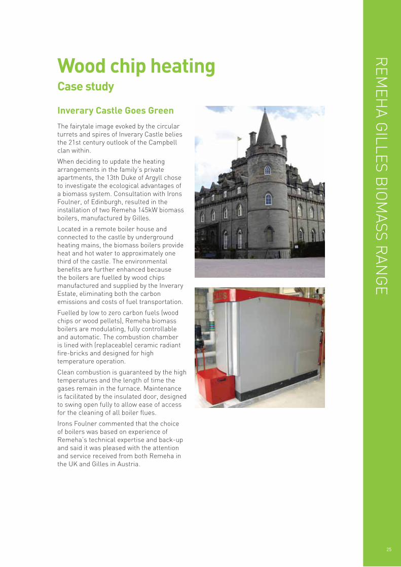
The fairytale image evoked by the circularturrets and spires of Inverary Castle beliesthe 21st century outlook of the Campbellclan within.
When deciding to update the heatingarrangements in the family’s privateapartments, the 13th Duke of Argyll choseto investigate the ecological advantages of a biomass system. Consultation with IronsFoulner, of Edinburgh, resulted in theinstallation of two Remeha 145kW biomassboilers, manufactured by Gilles.
Located in a remote boiler house andconnected to the castle by undergroundheating mains, the biomass boilers provideheat and hot water to approximately onethird of the castle. The environmentalbenefits are further enhanced because the boilers are fuelled by wood chipsmanufactured and supplied by the InveraryEstate, eliminating both the carbonemissions and costs of fuel transportation.
Fuelled by low to zero carbon fuels (woodchips or wood pellets), Remeha biomassboilers are modulating, fully controllableand automatic. The combustion chamber is lined with (replaceable) ceramic radiantfire-bricks and designed for hightemperature operation.
Clean combustion is guaranteed by the hightemperatures and the length of time thegases remain in the furnace. Maintenanceis facilitated by the insulated door, designedto swing open fully to allow ease of accessfor the cleaning of all boiler flues.
Irons Foulner commented that the choice of boilers was based on experience ofRemeha’s technical expertise and back-upand said it was pleased with the attentionand service received from both Remeha inthe UK and Gilles in Austria.
Inverary Castle Goes Green
26
PELLETS
Output[kW] @
nominal &part load
CO2-content [%][experience
average]
Flue gasmass flow
[m³/hr]
Flue gastemperature
[°C]
Residual fluefan pressure
[Pa] onautomatic
mode*
Ø Flue pipeconnection
Connectionheight [m]
HPK-RA12,5 / 5.1
12.5
3.5
12.6
9.7
21.9
7.6
170
120
8
1
160
1.4
HPK-RA14,5 / 5.1
14.5
4.5
12.6
9.7
25.4
9.6
170
120
8
1
160
1.4
HPK-RA19,5 / 5.1
19.5
5.5
12.6
9.7
35.6
13.0
170
120
8
2
160
1.4
HPK-RA15 / 6.1
15
5
12.6
9.7
26.3
9.9
170
120
10
1
160
1.6
HPK-RA20 / 6.1
20
6
12.6
9.7
36.5
9.9
170
120
10
3
160
1.6
HPK-RA25 / 6.1
25
8
12.6
9.7
45.6
17.0
170
120
10
5
160
1.6
HPK-RA30 / 9.2
30
9
12.6
9.7
52.8
19.8
170
120
10
5
180
1.9
HPK-RA35 / 9.2
35
11
12.6
9.7
62.8
23.5
170
120
11
6
180
1.9
HPK-RA40 / 9.2
40
12
12.6
9.7
72.9
27.0
170
120
10
6
180
1.9
HPK-RA45 / 9.2
45
14
12.6
9.7
78.9
29.8
170
120
9
7
180
1.9
HPK-RA49 / 9.2
49
15
12.6
9.7
86.0
32.3
170
120
9
7
180
1.90
HPK-RA60 / 2.1
60
18
12.6
9.7
108
39.9
170
120
11
6
200
2.05
HPK-RA70 / 3.1
70
21
12.6
9.7
128
47.1
170
120
9
8
200
2.05
HPK-RA75 / 3.1
75
23
12.6
9.7
134
49.9
170
120
8
8
200
2.05
HPK-RA85 / 3.1
85
26
12.6
9.7
153
57.2
170
120
6
6
200
2.05
HPK-RA95 / 10.1
95
26
12.6
9.7
174
65.0
170
120
12
10
250
2.05
HPK-RA100 / 10.1
100
30
12.6
9.7
174
65.4
170
120
12
10
250
2.05
HPK-RA120 / 10.1
120
36
12.6
9.7
212
79.8
170
120
10
10
250
2.05
HPK-RA145 / 4.2
145
44
12.6
9.7
260
97.5
170
120
6
5
250
2.05
HPK-RA150 / 4.2
153
51
12.6
9.7
275
113.0
170
120
6
5
250
2.05
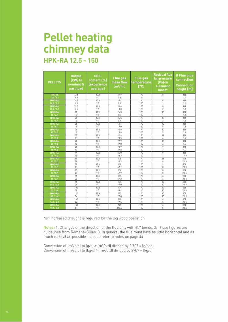
Pellet heatingchimney dataHPK-RA 12.5 - 150
*an increased draught is required for the log wood operation
Notes: 1. Changes of the direction of the flue only with 45° bends. 2. These figures areguidelines from Remeha-Gilles. 3. In general the flue must have as little horizontal and asmuch vertical as possible - please refer to notes on page 44
Conversion of [m³/std] to [g/s] > [m³/std] divided by 2,707 = [g/sec]Conversion of [m³/std] to [kg/s] > [m³/std] divided by 2707 = [kg/s]
REM
EHA G
ILLES BIO
MASS R
ANG
E
27
WOODCHIPS
Output[kW] @
nominal &part load
CO2-content [%][experience
average]
Flue gasmass flow
[m³/hr]
Flue gastemperature
[°C]
Residual fluefan pressure
[Pa] onautomatic
mode*
Ø Flue pipeconnection
Connectionheight [m]
HPK-RA20 / 8.2
20
7.9
12.6
9.7
42.0
19.9
170
120
12
6
180
1.9
HPK-RA25 / 8.2
25
7.9
12.6
9.7
53.9
19.9
170
120
11
7
180
1.9
HPK-RA30 / 8.2
30
9
12.6
9.7
61.7
22.7
170
120
11
6
180
1.9
HPK-RA35 / 8.2
35
11
12.6
9.7
73.9
27.0
170
120
11
7
180
1.9
HPK-RA40 / 8.2
40
12
12.6
9.7
86.3
31.3
170
120
9
8
180
1.9
HPK-RA45 / 8.2
45
15
12.6
9.7
97.5
35.5
170
120
8
8
180
1.9
HPK-RA49 / 8.2
49
15
12.6
9.7
101
37.1
170
120
8
8
180
1.9
HPK-RA60 / 2.1
60
18
12.6
9.7
126
46.0
170
120
10
9
200
2.05
HPK-RA70 / 3.1
70
21
12.6
9.7
151
54.4
170
120
7
7
200
2.05
HPK-RA75 / 3.1
75
23
12.6
9.7
157
57.7
170
120
6
6
200
2.05
HPK-RA85 / 3.1
85
26
12.6
9.7
181
65.8
170
12
3
3
200
2.05
HPK-RA95 / 10.1
95
29
12.6
9.7
204
75.0
170
120
11
10
250
2.05
HPK-RA100 / 10.1
100
30
12.6
9.7
205
75.3
170
120
11
10
250
2.05
HPK-RA120 / 10.1
120
36
12.6
9.7
248
91.8
170
120
6
6
250
2.05
HPK-RA145 / 4.2
145
44
12.6
9.7
307
113
170
120
7
7
250
2.05
HPK-RA150 / 4.2
150
49.5
12.6
9.7
318
127
190
120
6
5
250
2.05
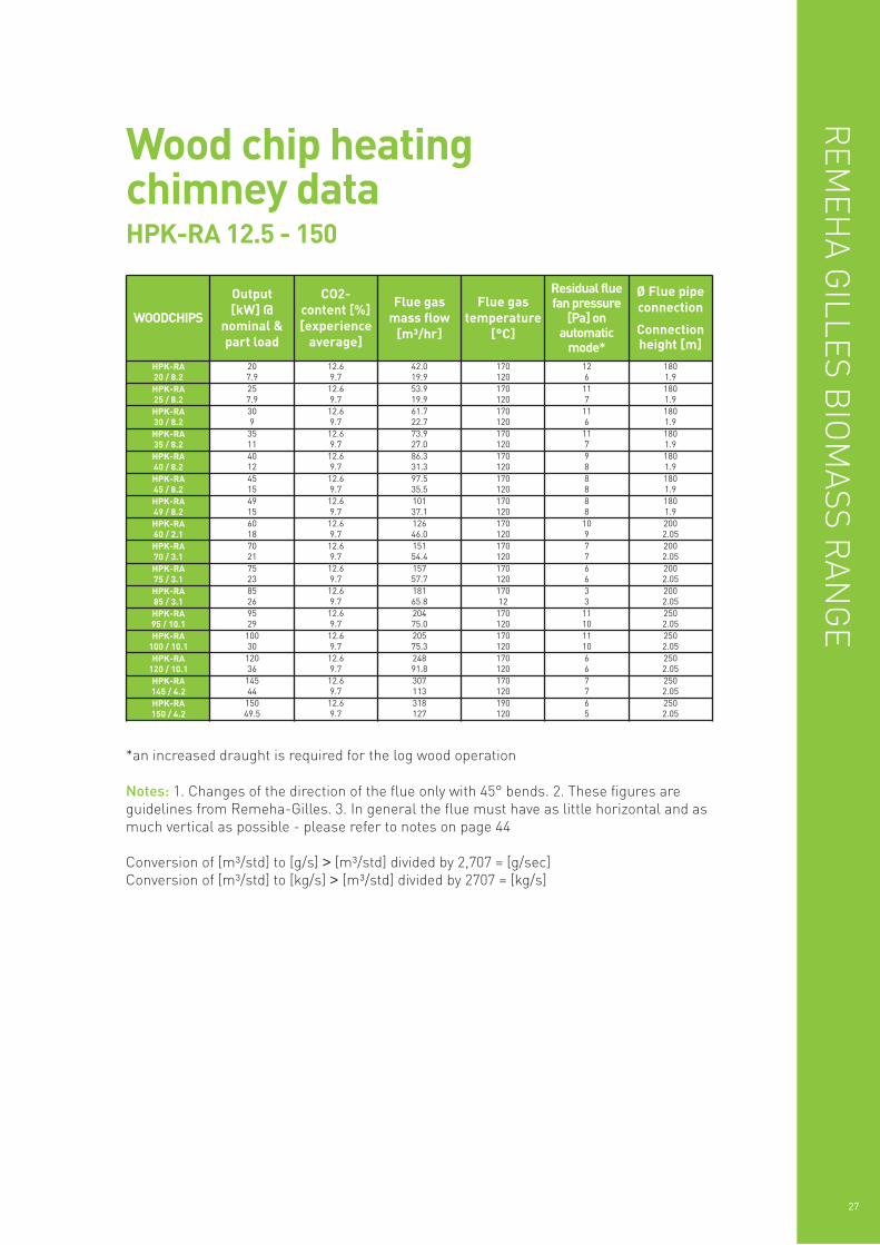
Wood chip heatingchimney dataHPK-RA 12.5 - 150
*an increased draught is required for the log wood operation
Notes: 1. Changes of the direction of the flue only with 45° bends. 2. These figures areguidelines from Remeha-Gilles. 3. In general the flue must have as little horizontal and asmuch vertical as possible - please refer to notes on page 44
Conversion of [m³/std] to [g/s] > [m³/std] divided by 2,707 = [g/sec]Conversion of [m³/std] to [kg/s] > [m³/std] divided by 2707 = [kg/s]
28
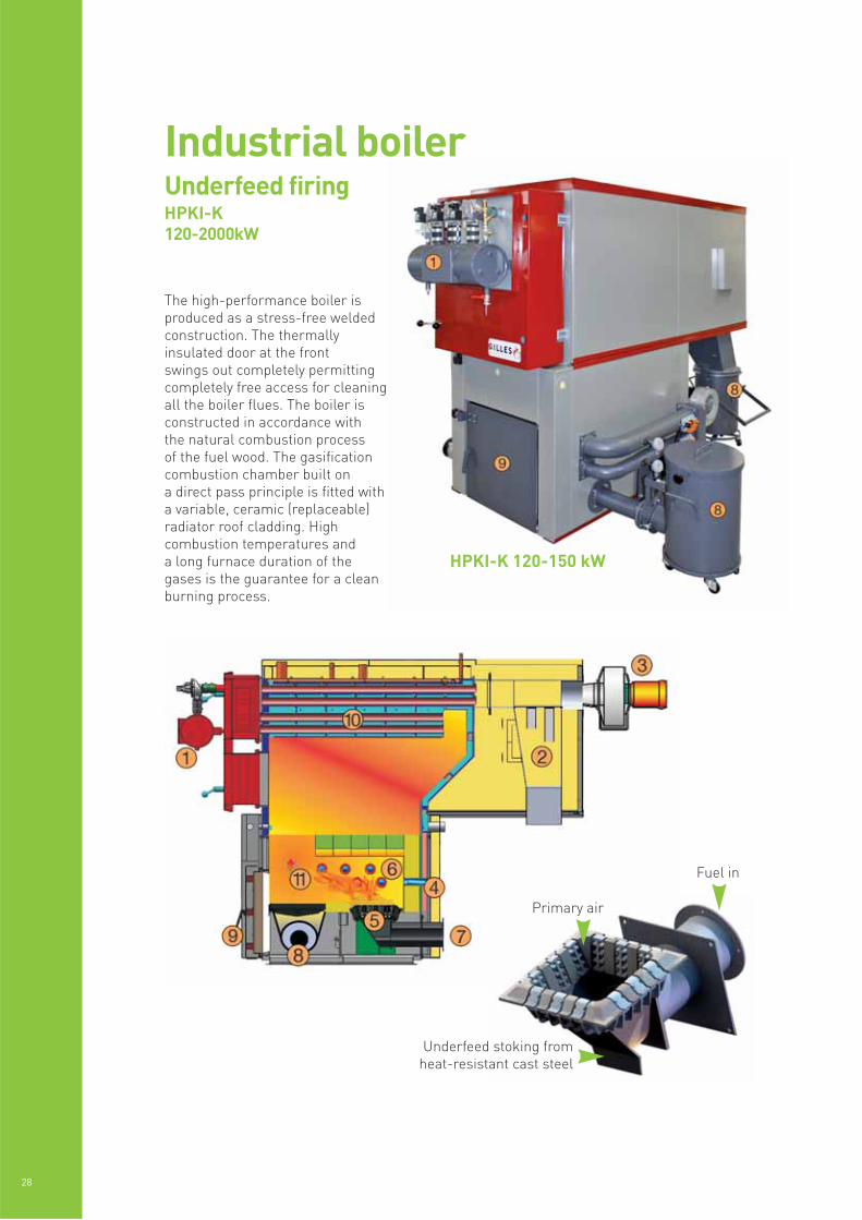
HPKI-K 120-150 kW
The high-performance boiler isproduced as a stress-free weldedconstruction. The thermallyinsulated door at the front swings out completely permittingcompletely free access for cleaningall the boiler flues. The boiler isconstructed in accordance with the natural combustion process of the fuel wood. The gasificationcombustion chamber built on a direct pass principle is fitted witha variable, ceramic (replaceable)radiator roof cladding. Highcombustion temperatures and a long furnace duration of thegases is the guarantee for a cleanburning process.
Industrial boilerUnderfeed firingHPKI-K120-2000kW
Underfeed stoking fromheat-resistant cast steel
Primary air
Fuel in
REM
EHA G
ILLES BIO
MASS R
ANG
E
29
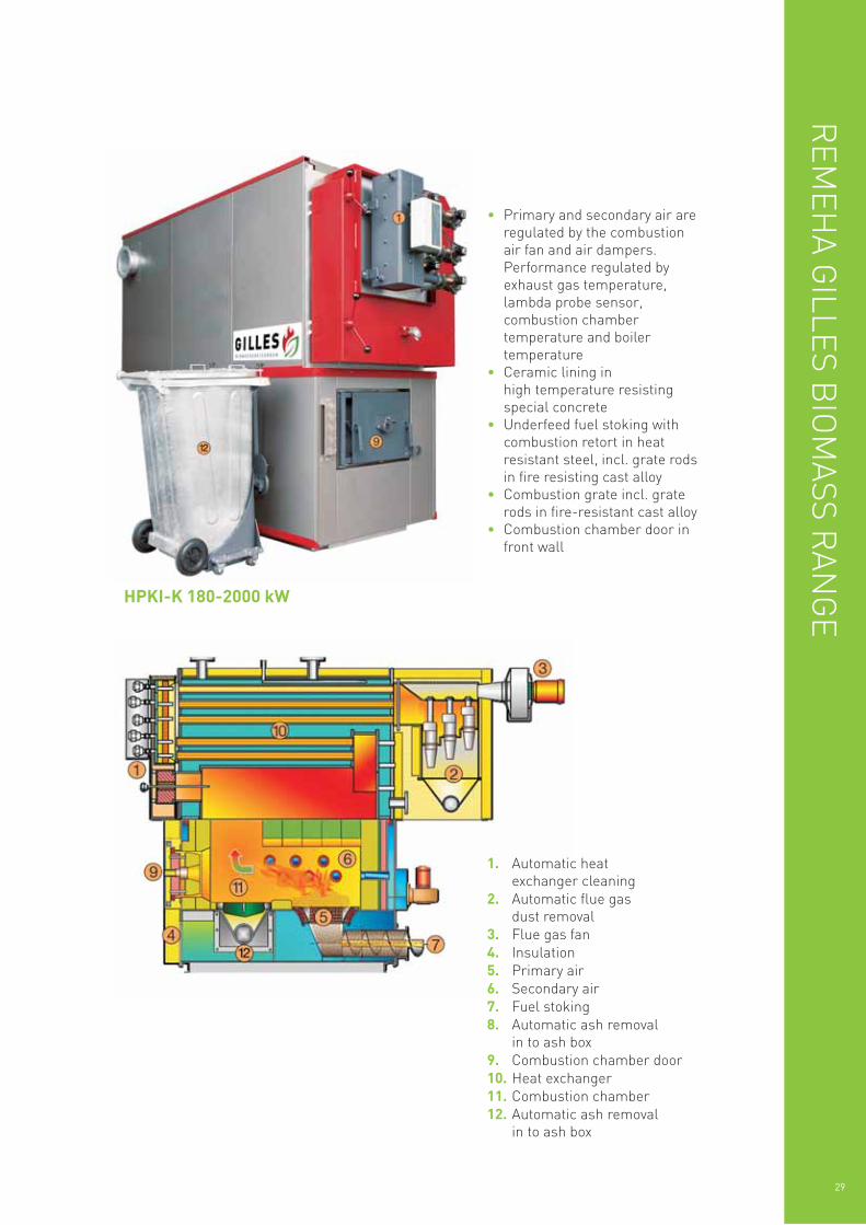
HPKI-K 180-2000 kW
1. Automatic heatexchanger cleaning
2. Automatic flue gasdust removal
3. Flue gas fan4. Insulation5. Primary air6. Secondary air7. Fuel stoking8. Automatic ash removal
in to ash box9. Combustion chamber door10. Heat exchanger11. Combustion chamber12. Automatic ash removal
in to ash box
• Primary and secondary air areregulated by the combustionair fan and air dampers.Performance regulated byexhaust gas temperature,lambda probe sensor,combustion chambertemperature and boilertemperature
• Ceramic lining inhigh temperature resistingspecial concrete
• Underfeed fuel stoking withcombustion retort in heatresistant steel, incl. grate rodsin fire resisting cast alloy
• Combustion grate incl. graterods in fire-resistant cast alloy
• Combustion chamber door infront wall
Grate element air-cooled
Wet fuels – air cooling
30
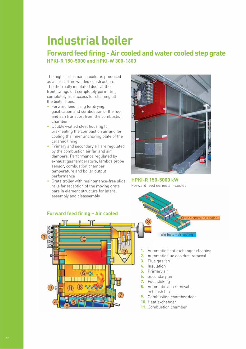
HPKI-R 150-5000 kWForward feed series air-cooled
The high-performance boiler is producedas a stress-free welded construction. The thermally insulated door at the front swings out completely permittingcompletely free access for cleaning all the boiler flues.• Forward feed firing for drying,
gasification and combustion of the fueland ash transport from the combustionchamber
• Double-walled steel housing forpre-heating the combustion air and forcooling the inner anchoring plate of theceramic lining
• Primary and secondary air are regulatedby the combustion air fan and airdampers. Performance regulated byexhaust gas temperature, lambda probesensor, combustion chambertemperature and boiler outputperformance
• Grate trolley with maintenance-free sliderails for reception of the moving gratebars in element structure for lateralassembly and disassembly
Industrial boilerForward feed firing - Air cooled and water cooled step grateHPKI-R 150-5000 and HPKI-W 300-1600
Forward feed firing – Air cooled
1. Automatic heat exchanger cleaning2. Automatic flue gas dust removal3. Flue gas fan4. Insulation5. Primary air6. Secondary air7. Fuel stoking8. Automatic ash removal
in to ash box9. Combustion chamber door10. Heat exchanger11. Combustion chamber
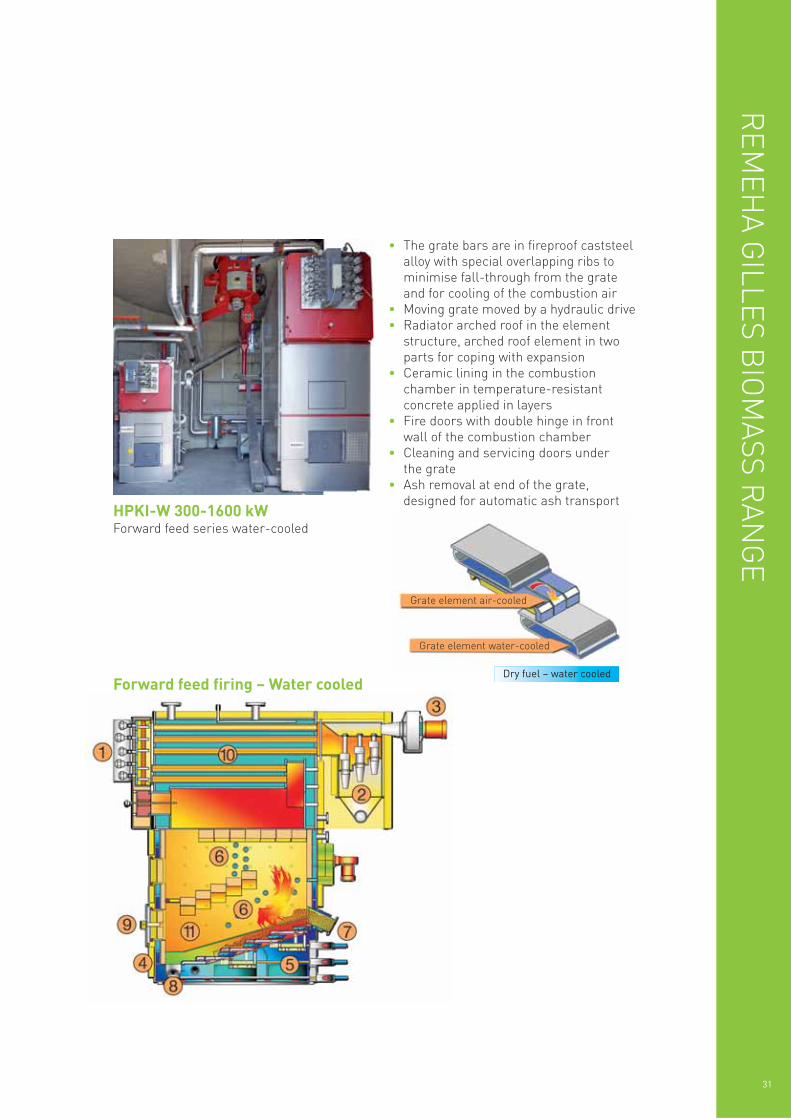
HPKI-W 300-1600 kWForward feed series water-cooled
Grate element air-cooled
REM
EHA G
ILLES BIO
MASS R
ANG
E
31
Forward feed firing – Water cooled
Grate element water-cooled
• The grate bars are in fireproof caststeelalloy with special overlapping ribs tominimise fall-through from the grateand for cooling of the combustion air
• Moving grate moved by a hydraulic drive• Radiator arched roof in the element
structure, arched roof element in twoparts for coping with expansion
• Ceramic lining in the combustionchamber in temperature-resistantconcrete applied in layers
• Fire doors with double hinge in frontwall of the combustion chamber
• Cleaning and servicing doors underthe grate
• Ash removal at end of the grate,designed for automatic ash transport
Dry fuel – water cooled
RD ø
5 6 12
317L
2
8
195
9
180
955
11
B
4
10
H
32
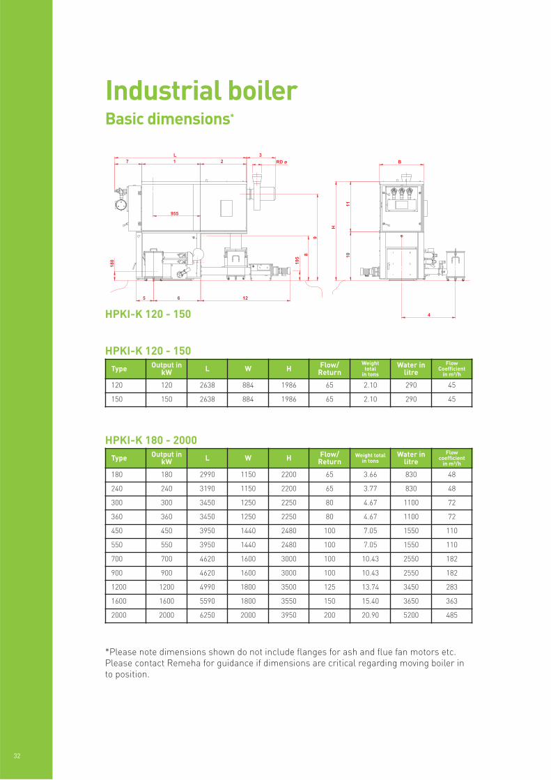
Industrial boilerBasic dimensions*
HPKI-K 120 - 150
HPKI-K 180 - 2000
Type Output inkW L W H Flow/
ReturnWeight
totalin tons
Water inlitre
FlowCoefficient
in m³/h
120 120 2638 884 1986 65 2.10 290 45
150 150 2638 884 1986 65 2.10 290 45
Type Output inkW L W H Flow/
ReturnWeight total
in tonsWater in
litreFlow
coefficientin m³/h
180 180 2990 1150 2200 65 3.66 830 48
240 240 3190 1150 2200 65 3.77 830 48
300 300 3450 1250 2250 80 4.67 1100 72
360 360 3450 1250 2250 80 4.67 1100 72
450 450 3950 1440 2480 100 7.05 1550 110
550 550 3950 1440 2480 100 7.05 1550 110
700 700 4620 1600 3000 100 10.43 2550 182
900 900 4620 1600 3000 100 10.43 2550 182
1200 1200 4990 1800 3500 125 13.74 3450 283
1600 1600 5590 1800 3550 150 15.40 3650 363
2000 2000 6250 2000 3950 200 20.90 5200 485
HPKI-K 120 - 150
*Please note dimensions shown do not include flanges for ash and flue fan motors etc.Please contact Remeha for guidance if dimensions are critical regarding moving boiler into position.

REM
EHA G
ILLES BIO
MASS R
ANG
E
33
HPKI-W 300 - 1600 - Forward feed firing – Water cooled
Type Output inkW L W H Flow/
ReturnWeight
totalin tons
Waterin litre
Flowcoefficient
in m³/h
300 300 3450 1250 3000 80 7200 1700 72
360 360 3450 1250 3000 80 7200 1700 72
450 450 3950 1440 3300 100 10650 2350 110
550 550 3950 1440 3300 100 10650 2350 110
700 700 4620 1600 4100 100 15900 3850 182
900 900 4620 1600 4100 100 16000 3850 182
1200 1200 4990 1800 4800 125 21150 5550 283
1600 1600 5590 1800 4950 150 25000 6100 363
HPKI-R 150-5000 - Forward feed firing – Air cooled
Type Output inkW L W H Flow/
ReturnWeight
totalin tons
Water in litreFlow
coefficientin m³/h
150 150 2890 950 2420 50 3.97 290 30
180 180 2990 1150 2600 65 4.75 830 48
240 240 3190 1150 2600 65 4.8 830 48
300 300 3450 1250 2650 80 5.6 1100 72
360 360 3450 1250 2650 80 5.6 1100 72
450 450 3950 1440 2900 100 9.5 1550 110
550 550 3950 1440 2900 100 9.5 1550 110
700 700 4620 1800 3550 100 14.6 2550 182
900 900 4620 1800 3550 100 14.7 2550 182
1200 1200 4990 2000 4050 125 22.2 3450 283
1600 1600 5590 2000 4100 150 24.7 3650 363
2000 2000 6250 2320 4950 200 27.8 5200 485
2400 2400 6850 2320 4950 200 36.0 6050 515
3200 3200 7910 2800 6800 200 61.5 14300 640
4200 4200 9090 2800 7000 250 72.0 21600 840
5000 5000 10810 2800 8100 250 97.0 21600 1100
HPKI-K 180 - 2000, HPKI-R 150-5000 and HPKI-W 300 - 1600
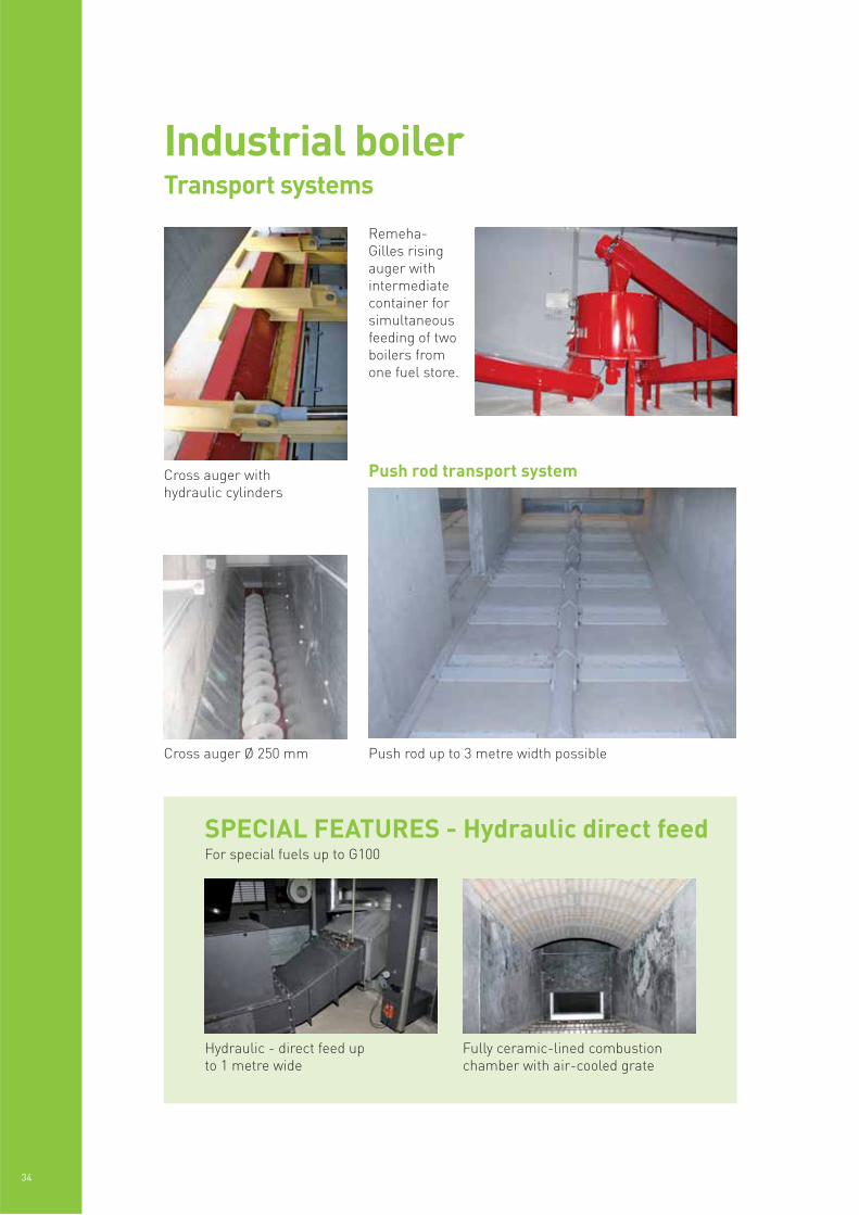
Remeha-Gilles risingauger withintermediatecontainer forsimultaneousfeeding of twoboilers fromone fuel store.
Cross auger Ø 250 mm Push rod up to 3 metre width possible
Cross auger withhydraulic cylinders
34
Industrial boilerTransport systems
SPECIAL FEATURES - Hydraulic direct feedFor special fuels up to G100
Hydraulic - direct feed upto 1 metre wide
Fully ceramic-lined combustionchamber with air-cooled grate
Push rod transport system
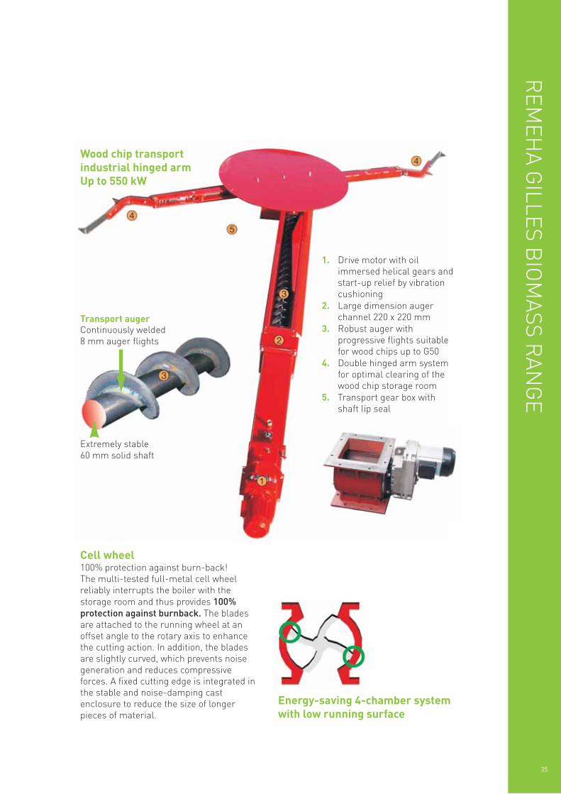
1. Drive motor with oilimmersed helical gears andstart-up relief by vibrationcushioning
2. Large dimension augerchannel 220 x 220 mm
3. Robust auger withprogressive flights suitablefor wood chips up to G50
4. Double hinged arm systemfor optimal clearing of thewood chip storage room
5. Transport gear box withshaft lip seal
Cell wheel100% protection against burn-back!The multi-tested full-metal cell wheelreliably interrupts the boiler with thestorage room and thus provides 100%protection against burnback. The bladesare attached to the running wheel at anoffset angle to the rotary axis to enhancethe cutting action. In addition, the bladesare slightly curved, which prevents noisegeneration and reduces compressiveforces. A fixed cutting edge is integrated inthe stable and noise-damping castenclosure to reduce the size of longerpieces of material.
Energy-saving 4-chamber systemwith low running surface
REM
EHA G
ILLES BIO
MASS R
ANG
E
35
Transport augerContinuously welded8 mm auger flights
Extremely stable60 mm solid shaft
Wood chip transportindustrial hinged armUp to 550 kW
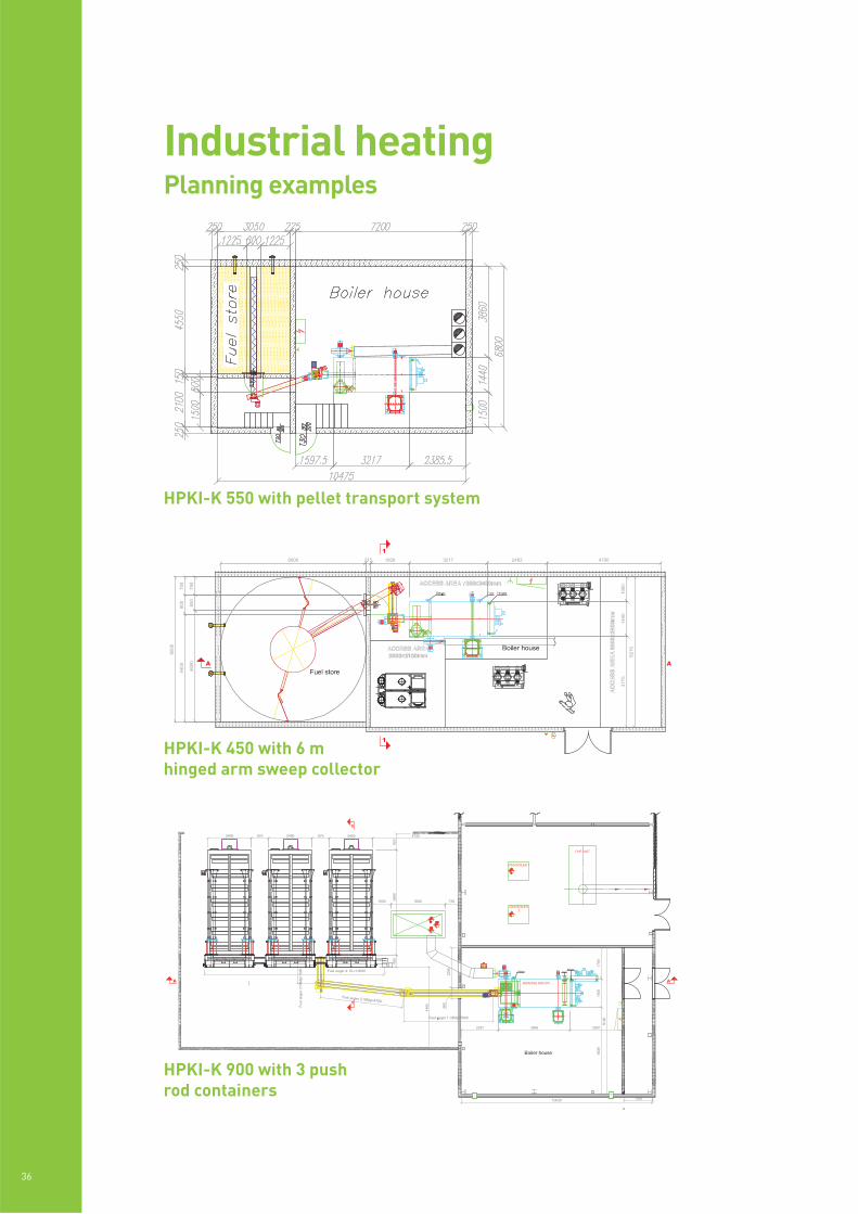
HPKI-K 550 with pellet transport system
36
Industrial heatingPlanning examples
HPKI-K 900 with 3 pushrod containers
HPKI-K 450 with 6 mhinged arm sweep collector

REM
EHA G
ILLES BIO
MASS R
ANG
E
37
Industrial heatingCase study
State-of-the-art biomass boiler technologyfrom Remeha has ensured that StanstedAirport’s new £50million terminal extensionis a low to zero carbon zone. And, saysStansted’s head of environment, the boilerhas outperformed all expectations duringits first winter of operation.
The 2000kW biomass heating boiler is oneof the biggest in commercial use in the UK.Supplied by Remeha and manufactured byEuropean company Gilles Austria, it ispowered by woodchips.
The boiler is part of BAA’s commitment to reducing the environmental impacts ofdevelopment and day-to-day operations. It makes the new airport extension,completed last year, a low to zerocarbon building.
Indeed its performance since lastNovember has proved so efficient that is itnow the primary boiler for the wholeairport. Results indicate the biomasstechnology is set to help reduce predictedannual gas consumption at the airport bynearly 40 per cent.
“To say we’re delighted with theperformance of the new biomass boiler is an understatement,” says head ofenvironment at Stansted Airport, Andy Jefferson.
“We set out to ensure the recent terminalextension would be carbon neutral butperformance data so far indicates thosesavings go much further, with resultsbetween November 2008 and March 2009alone showing that gas consumption atStansted was around 60 per cent of thepredicted forecasts for this period, and over30 per cent lower than the same period forthe previous year. And all this despite itbeing one of the coldest winters on recordfor over a decade.
“Whilst initiatives such as our assetreplacement programme have contributed
to these overall results, the introduction ofbiomass technology has by far been thelargest contributor.
“We’re proud to maintain our leadingposition as the largest UK airport to holdISO14001 accreditation for environmentalmanagement and shall also publish ourfirst Airport Carbon Footprint before thissummer which will outline how ourfootprint is comprised today, and helpinform future decisions relating toemissions management at Stanstedmoving forward.”
Remeha’s Stansted Airport biomass installationoutperforms all expectations
38
PELLETS
Output[kW] @
nominal &part load
CO2- content [%][experience
average]
Flue gasmass flow
[m³/hr]
Flue gastemperature
[°C]
Residual fluefan pressure
[Pa] onautomatic
mode
Ø Flue pipeconnection+ Flue pipe
[mm]
Ø Chimney[mm]
HPKI-K120
120
40
12.6
9.7
215
88.7
170
120
9
8
200
250250
HPKI-K150
150
45
12.6
9.7
266.0
99.8
170
120
8
8
200
250250
HPKI-K (R,W)180
180
54
12.6
9.7
326.0
121
170
120
8
5
200
250250
HPKI-K (R,W)240
240
72
12.6
9.7
423.2
158
170
120
8
7
200
300300
HPKI-K (R,W)300
300
90
12.6
9.7
537.9
74.5
170
120
12
11
200
300300
HPKI-K (R,W)360
360
108
12.6
9.7
656.4
243.4
170
120
11
11
250
350350
HPKI-K (R,W)450
450
135
12.6
9.7
797.9
298.3
170
120
9
9
300
400400
HPKI-K (R,W)550
550
165
12.6
9.7
1003
374.0
170
120
11
11
300
400450
HPKI-K (R,W)700
700
210
12.6
9.7
1234
461.6
170
120
9
7
300
400450
HPKI-K (R,W)900
900
270
12.6
9.7
1641
608.5
170
120
9
7
360
500500
HPKI-K (R,W)1200
1200
360
12.6
9.7
2163
802.5
170
120
11
11
400
550600
HPKI-K (R,W)1600
1600
480
12.6
9.7
2901
1076
170
120
13
13
400
550600
HPKI-K ( R )2000
2000
600
12.6
9.7
3647
1345
170
120
13
11
400
600600
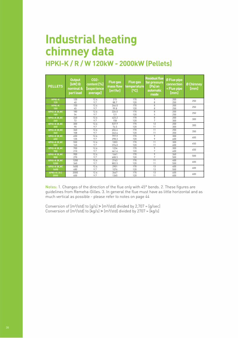
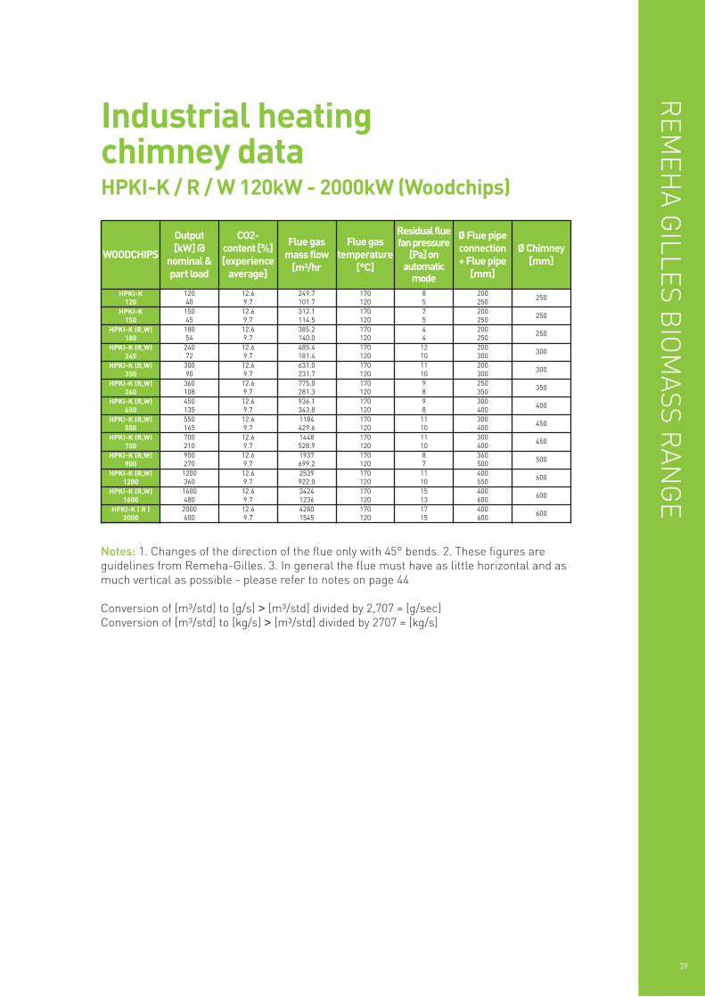
Industrial heatingchimney dataHPKI-K / R / W 120kW - 2000kW (Pellets)
Notes: 1. Changes of the direction of the flue only with 45° bends. 2. These figures areguidelines from Remeha-Gilles. 3. In general the flue must have as little horizontal and asmuch vertical as possible - please refer to notes on page 44
Conversion of [m³/std] to [g/s] > [m³/std] divided by 2,707 = [g/sec]Conversion of [m³/std] to [kg/s] > [m³/std] divided by 2707 = [kg/s]
REM
EHA G
ILLES BIO
MASS R
ANG
E
39
WOODCHIPS
Output[kW] @
nominal &part load
CO2-content [%][experience
average]
Flue gasmass flow
[m³/hr
Flue gastemperature
[°C]
Residual fluefan pressure
[Pa] onautomatic
mode
Ø Flue pipeconnection+ Flue pipe
[mm]
Ø Chimney[mm]
HPKI-K120
120
40
12.6
9.7
249.7
101.7
170
120
8
5
200
250250
HPKI-K150
150
45
12.6
9.7
312.1
114.5
170
120
7
5
200
250250
HPKI-K (R,W)180
180
54
12.6
9.7
385.2
140.0
170
120
4
4
200
250250
HPKI-K (R,W)240
240
72
12.6
9.7
485.4
181.4
170
120
12
10
200
300300
HPKI-K (R,W)300
300
90
12.6
9.7
631.0
231.7
170
120
11
10
200
300300
HPKI-K (R,W)360
360
108
12.6
9.7
775.0
281.3
170
120
9
8
250
350350
HPKI-K (R,W)450
450
135
12.6
9.7
936.1
343.8
170
120
9
8
300
400400
HPKI-K (R,W)550
550
165
12.6
9.7
1184
429.6
170
120
11
10
300
400450
HPKI-K (R,W)700
700
210
12.6
9.7
1448
528.9
170
120
11
10
300
400450
HPKI-K (R,W)900
900
270
12.6
9.7
1937
699.2
170
120
8
7
360
500500
HPKI-K (R,W)1200
1200
360
12.6
9.7
2539
922.0
170
120
11
10
400
550600
HPKI-K (R,W)1600
1600
480
12.6
9.7
3424
1236
170
120
15
13
400
600600
HPKI-K ( R )2000
2000
600
12.6
9.7
4280
1545
170
120
17
15
400
600600
Industrial heatingchimney dataHPKI-K / R / W 120kW - 2000kW (Woodchips)
Notes: 1. Changes of the direction of the flue only with 45° bends. 2. These figures areguidelines from Remeha-Gilles. 3. In general the flue must have as little horizontal and asmuch vertical as possible - please refer to notes on page 44
Conversion of [m³/std] to [g/s] > [m³/std] divided by 2,707 = [g/sec]Conversion of [m³/std] to [kg/s] > [m³/std] divided by 2707 = [kg/s]
40
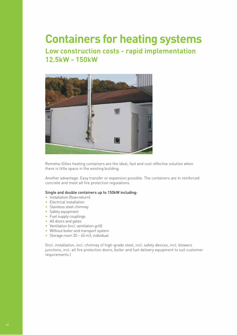
Remeha-Gilles heating containers are the ideal, fast and cost-effective solution whenthere is little space in the existing building.
Another advantage: Easy transfer or expansion possible. The containers are in reinforcedconcrete and meet all fire protection regulations.
Single and double containers up to 150kW including:• Installation (flow+return)• Electrical installation• Stainless steel chimney• Safety equipment• Fuel supply couplings• All doors and gates• Ventilation (incl. ventilation grill)• Without boiler and transport system• Storage room 20 – 45 m3, individual
(Incl. installation, incl. chimney of high-grade steel, incl. safety devices, incl. blowersjunctions, incl. all fire protection doors, boiler and fuel delivery equipment to suit customerrequirements.)
Containers for heating systemsLow construction costs - rapid implementation12.5kW - 150kW
REM
EHA G
ILLES BIO
MASS R
ANG
E
41
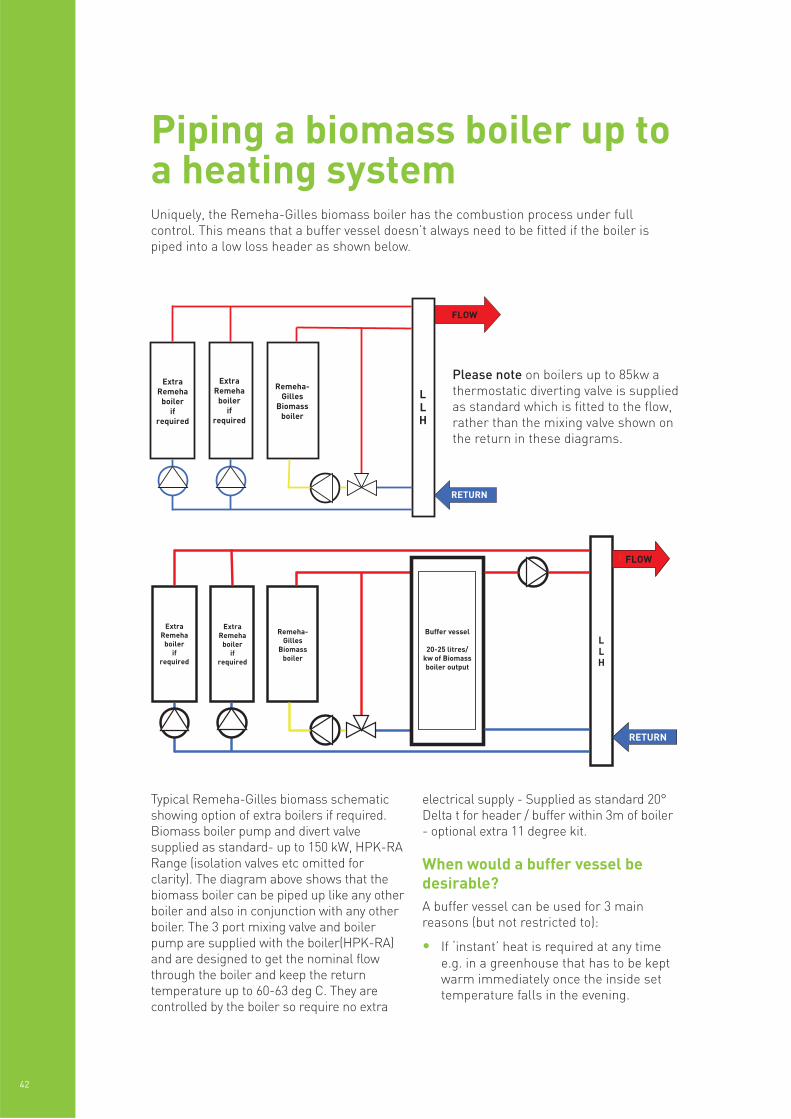
Typical Remeha-Gilles biomass schematicshowing option of extra boilers if required.Biomass boiler pump and divert valvesupplied as standard- up to 150 kW, HPK-RARange (isolation valves etc omitted forclarity). The diagram above shows that thebiomass boiler can be piped up like any otherboiler and also in conjunction with any otherboiler. The 3 port mixing valve and boilerpump are supplied with the boiler(HPK-RA)and are designed to get the nominal flowthrough the boiler and keep the returntemperature up to 60-63 deg C. They arecontrolled by the boiler so require no extra
electrical supply - Supplied as standard 20°Delta t for header / buffer within 3m of boiler- optional extra 11 degree kit.
When would a buffer vessel bedesirable?A buffer vessel can be used for 3 mainreasons (but not restricted to):
• If ‘instant’ heat is required at any timee.g. in a greenhouse that has to be keptwarm immediately once the inside settemperature falls in the evening.
42
Piping a biomass boiler up toa heating systemUniquely, the Remeha-Gilles biomass boiler has the combustion process under fullcontrol. This means that a buffer vessel doesn’t always need to be fitted if the boiler ispiped into a low loss header as shown below.
Please note on boilers up to 85kw athermostatic diverting valve is suppliedas standard which is fitted to the flow,rather than the mixing valve shown onthe return in these diagrams.
For exampleA 145kw boiler in a primary school workingsay 6hrs a day at full output burning woodchips will burn the following amount of fuelper week.
145kw x 6hrs per day x 5 days per week =4350 kw/hrs per week.
4350 divided by 800 (the amount of kw/hrsper m3 of chips) = 5.43m3 per week.
Most fuel delivery lorries carry about 30m3of fuel so in this instance if a 36/38m3 storecould be created a delivery would beneeded about every 6 weeks without thestore needing to be fully empty to receive afull load.
A suitable store would be about 3.5m x 3.5mx 3m deep.
Another exampleA 100kw boiler in a sports centre workingsay 12hrs a day at full output burningpellets will burn the following amount offuel per week.
100kw x 12hrs per day x 7 days per week =8400kw/hrs per week.
8400 divided by 3000 (the amount of kw/hrsper m3 of pellets) = 2.8m3 per week.
That would be a full lorry load approx every10 weeks or a half load every month or so.
What capacity does the fuelstore need to be?
REM
EHA G
ILLES BIO
MASS R
ANG
E
43
• A buffer vessel can be used to effectivelyincrease the size of a boiler by letting itcreate and store heat overnight ready forthe cold morning start - this applies to allboilers not just biomass.
• If the boiler is connected only to a PlateHeat Exchanger/s and/or if there is a
possibility of the demand for heat beingtaken away without any overrun e.g. onlylooking after air handling units whichmay all switch off at the same time oncea set outside temperature is reached orsimilar situation.
Calculation is dependent upon a number of factors:
• What output is the biomass boiler in kw?
• How many hours a week will it be in operation?
• Which type of fuel – chips or pellets?
• How often is it desirable to have fuel deliveries?
• What capacity is the delivery lorry?
Important informationWater treatmentIt is generally considered good practice totreat the system water. The biomass boilershave a steel heat exchanger so a suitableinhibitor should be used for steel and allother metals in the heating system.
Combustion air requirementsThe combustion air requirement for thebiomass boilers is as follows:
- Kw output of the boiler(s) x 3.222 + 80cm/2
- For example a 145 kW boiler would need547cm/2 of free area air inlet
- A 100 kW and 45 kW together in the sameboiler house would also need 547cm/2
Any conventionally flued appliances e.g.pressure jet, water heater, atmospheric orconventionally flued Quinta/210 etc willneed their combustion air in addition to theabove in accordance with standard BS6644calculation.
Flueing requirementsThe boilers must be connected to a fluewith natural draught- long horizontal andshort vertical runs are to be avoided. Fluefans- supplied by others- can beincorporated but add additional cost andcomplexity to the project. Boilers must beflued in accordance with BS 6644 andcomply with the requirements of the CleanAir Act.
Reference should be made BS 6644 & theClean Air Act.
Only clean wood fuel may be used & cangenerally be regarded as a Very LowSulphur (VLS) fuel.
- The boilers must have their own flue, theycannot share with other boilers, waterheaters or biomass boilers.
- The flue gas temperature is between 130deg C and 200 deg C.
- The services of a specialist flue companyshould be considered for final flue design,which should include clean out hatches,draught stabilisers and explosion doors.
Flueing environmental issuesAll combustion causes pollution. Whenselecting your fuel you are also inevitably
selecting the pollution that comes as aconsequence of that decision. All Remeha-Gilles boilers when correctly installed arecertified by AEA Technology* as suitable foruse in Smokeless Zones and meet with allUK regulatory standards. All equipmentcertification is given based on the use ofclean fuel. Clean fuel is essential otherwiseyou may be in breach of emissionsregulations.
Other air pollutants of concern, but by nomeans exclusive to biomass combustioninclude:
PM10 Particles - Remeha-Gilles fullyautomated boilers are class leaders withlow PM10 emissions.
PM10 Levels will vary significantly with fuelquality. Pellets produce less PM10 thanchips and may be a more suitable fuelchoice for built up areas. PM10 emissionsare of less concern in rural and suburbanareas where existing PM10 levels are likelyto be low. PM10 and 2.5 can be reduced tovirtually zero with the use of ceramic filterson the flue outlet, available from Remeha.
Sulfur Oxides (SOx) cause acid rain.Modern wood systems have 1/6 the SO2emissions of fuel oil.
Nitrogen Oxides (NOx) produced by allcombustion processes cause ozone, smog,acid rain and respiratory problems.
Carbon Monoxide (CO) is produced by allfuel combustion processes. The levelproduced by wood combustion depends verymuch on how well the system is set up andmaintained. CO emissions from woodburning are of relatively minor concern toair quality, except in some areas thatalready have high levels of CO in the airfrom traffic exhaust.
Volatile Organic Compounds (VOCs) are alarge family of air pollutants, some of whichare produced by fuel combustion. Some aretoxic, others are carcinogenic. VOCs elevateozone and smog levels in the loweratmosphere, causing respiratory problems.Both wood and oil combustion produceVOCs—wood is higher in some compoundsand oil is higher in others. VOC emissionscan be minimized with good combustionpractices.
44
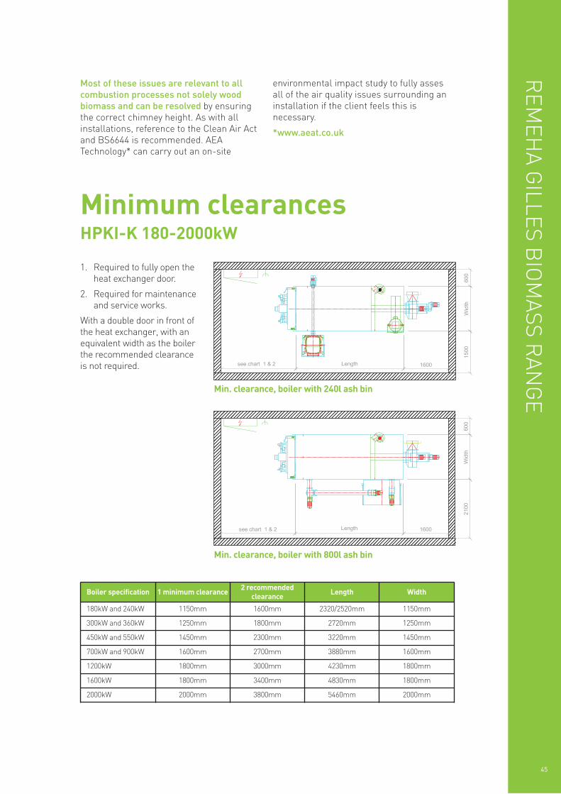
Minimum clearancesHPKI-K 180-2000kW
1. Required to fully open theheat exchanger door.
2. Required for maintenanceand service works.
With a double door in front ofthe heat exchanger, with anequivalent width as the boilerthe recommended clearanceis not required.
REM
EHA G
ILLES BIO
MASS R
ANG
E
45
Most of these issues are relevant to allcombustion processes not solely woodbiomass and can be resolved by ensuringthe correct chimney height. As with allinstallations, reference to the Clean Air Actand BS6644 is recommended. AEATechnology* can carry out an on-site
environmental impact study to fully assesall of the air quality issues surrounding aninstallation if the client feels this isnecessary.
*www.aeat.co.uk
Min. clearance, boiler with 800l ash bin
Boiler specification 1 minimum clearance 2 recommendedclearance Length Width
180kW and 240kW 1150mm 1600mm 2320/2520mm 1150mm
300kW and 360kW 1250mm 1800mm 2720mm 1250mm
450kW and 550kW 1450mm 2300mm 3220mm 1450mm
700kW and 900kW 1600mm 2700mm 3880mm 1600mm
1200kW 1800mm 3000mm 4230mm 1800mm
1600kW 1800mm 3400mm 4830mm 1800mm
2000kW 2000mm 3800mm 5460mm 2000mm
Min. clearance, boiler with 240l ash bin
46
Remeha is committed to carbon offsetting
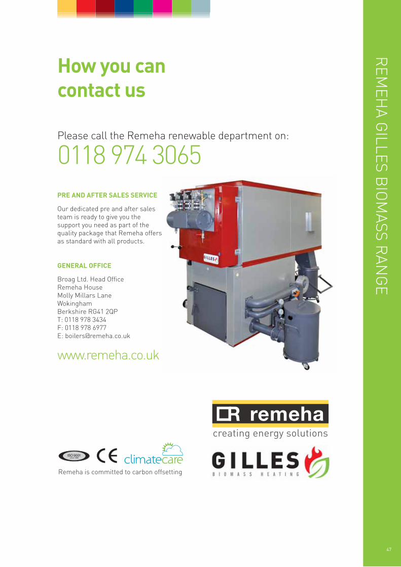
PRE AND AFTER SALES SERVICE
Our dedicated pre and after salesteam is ready to give you thesupport you need as part of thequality package that Remeha offersas standard with all products.
GENERAL OFFICE
Broag Ltd. Head OfficeRemeha HouseMolly Millars LaneWokinghamBerkshire RG41 2QPT: 0118 978 3434F: 0118 978 6977E: [email protected]
www.remeha.co.uk
How you can contact us
Please call the Remeha renewable department on:
0118 974 3065
REM
EHA G
ILLES BIO
MASS R
ANG
E
47
Des
igne
d an
d pr
oduc
ed b
y Sa
ns F
ront
iere
Mar
ketin
g C
omm
unic
atio
ns –
012
73 4
87 8
00 –
ww
w.s
ansf
ront
iere
.co.
uk
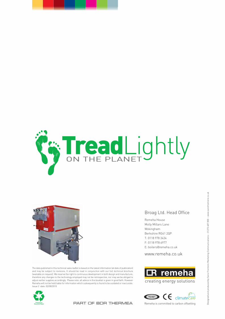
Broag Ltd. Head OfficeRemeha HouseMolly Millars LaneWokinghamBerkshire RG41 2QPT: 0118 978 3434F: 0118 978 6977E: [email protected]
www.remeha.co.uk
Remeha is committed to carbon offsetting
The data published in this technical sales leaflet is based on the latest information (at date of publication)and may be subject to revisions. It should be read in conjunction with our full technical brochure(available on request). We reserve the right to continuous development in both design and manufacture,therefore any changes to the technology employed may not be retrospective, nor may we be obliged toadjust earlier supplies accordingly. Please note: all advice in this booklet is given in good faith. HoweverRemeha will not be held liable for information which subsequently is found to be outdated or inaccurate.Issue 2 date: 02/08/2010