Embed Size (px)
Citation preview

Wood Frame Building EnclosuresLESSONS LEARNED FROM THE WET COAST
PRESENTATION FOR BUILDING ENCLOSURE COUNCIL – GREATER DETROIT
OCTOBER 20, 2015
MICHAEL AOKI-KRAMER, LEED™ AP, PRINCIPAL

RDH – Who We Are
à 170+ staff in 7 offices
à Canadian offices: Toronto, Vancouver, Victoria, Courtney
à US offices: Seattle, Portland, SF Bay Area (Oakland)
à All Focused in Building Science
à Existing Buildings
à New Building Consulting
à Research & ForensicsNew
Research
Existing
RDH Building Sciences – What we Believe
àMaking Buildings Better
à More durable
à More energy efficient
à More comfortable and inspiring to occupants
à Increased building performance can be achieved in a cost effective manner and be still be a durable, effective, and inspiring building
à Buildings Matter
à To the people that occupy them
à To those that design, finance, and own them
à To the community they exist in
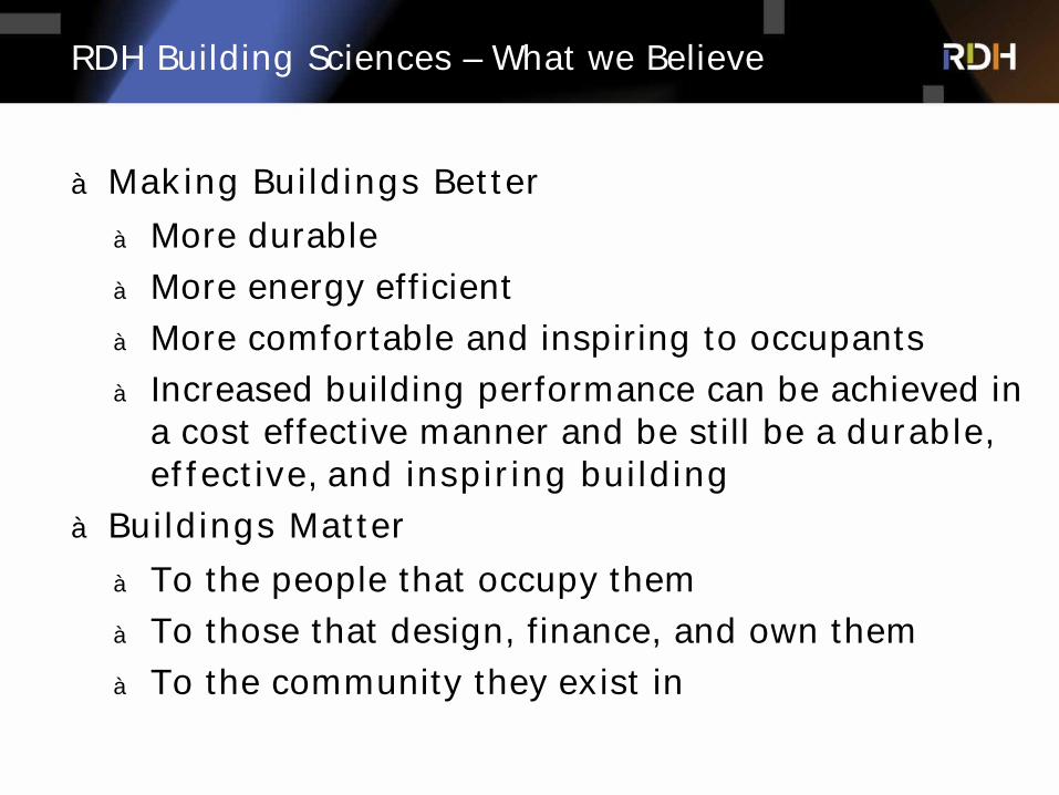
Agenda
à Why not older buildings?
à Performance Expectations and Selecting Wall Assemblies
à Below Grade Waterproofing (below water table and above)
à Details consistently commented on:
à air barriers,
à weather resistive barriers,
à water shedding continuity
à How to build big wood buildings
à Exterior Wall Design, Exterior Insulation
à Roof Assembly Design
à What is different about the way things used to be built vs. the way we build today?
à Does it matter?
Why Not Older Buildings?
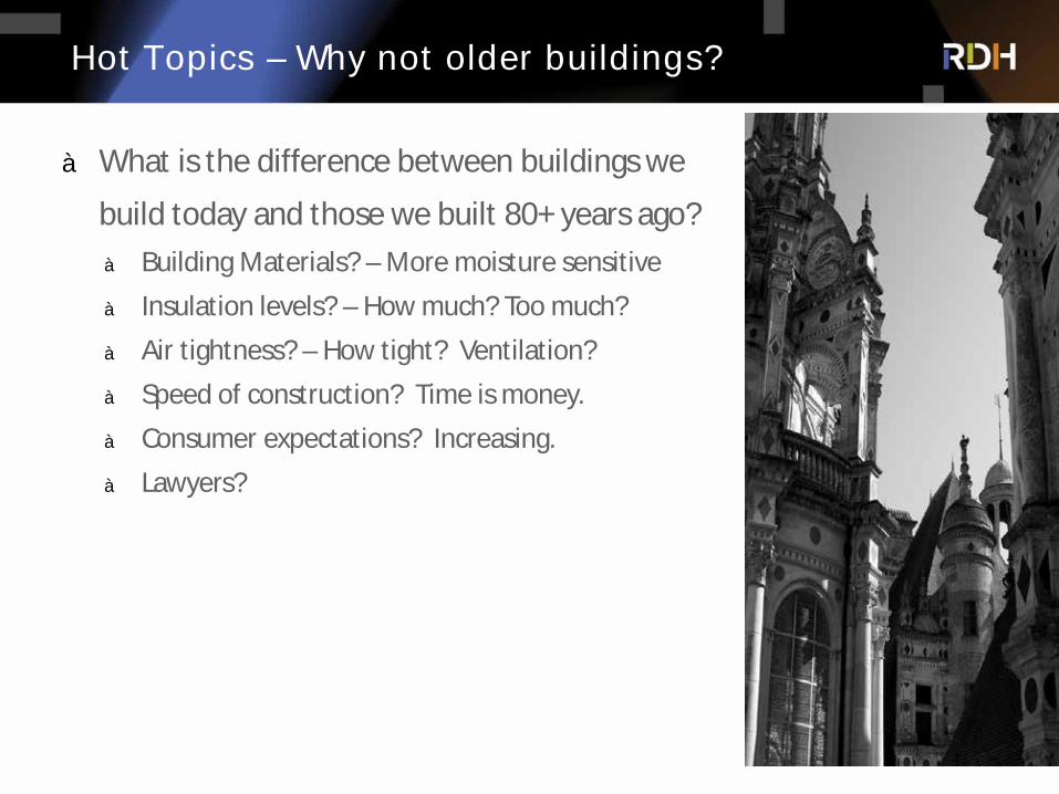
Hot Topics – Why not older buildings?
à What is the difference between buildings we
build today and those we built 80+ years ago?à Building Materials? – More moisture sensitive
à Insulation levels? – How much? Too much?
à Air tightness? – How tight? Ventilation?
à Speed of construction? Time is money.
à Consumer expectations? Increasing.
à Lawyers?
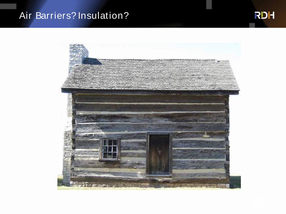
Air Barriers? Insulation?
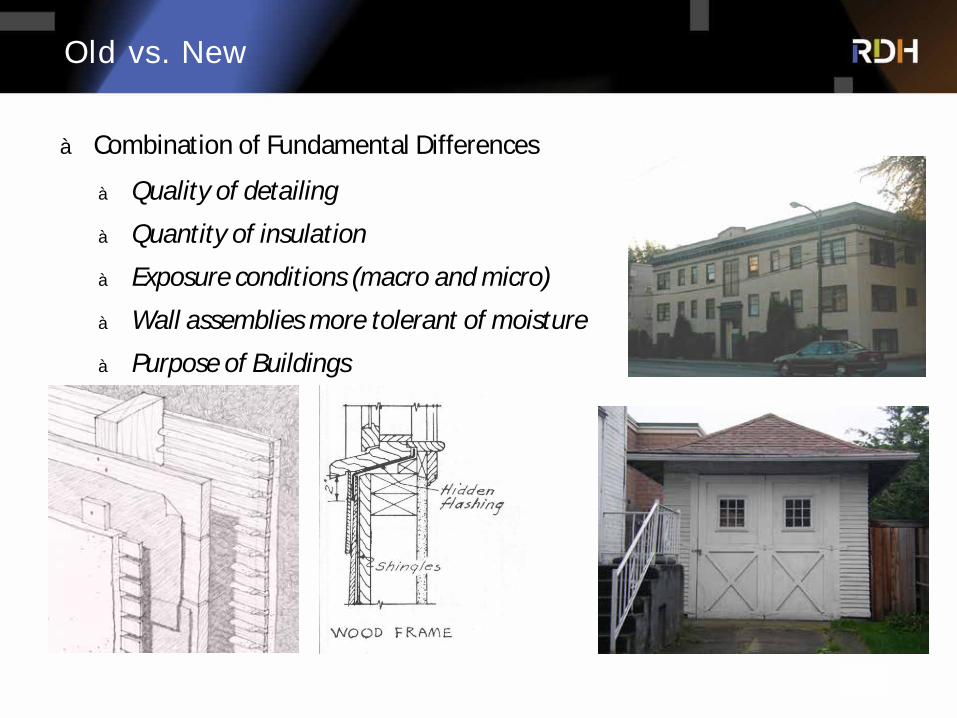
Old vs. New
à Combination of Fundamental Differences
à Quality of detailing
à Quantity of insulation
à Exposure conditions (macro and micro)
à Wall assemblies more tolerant of moisture
à Purpose of Buildings
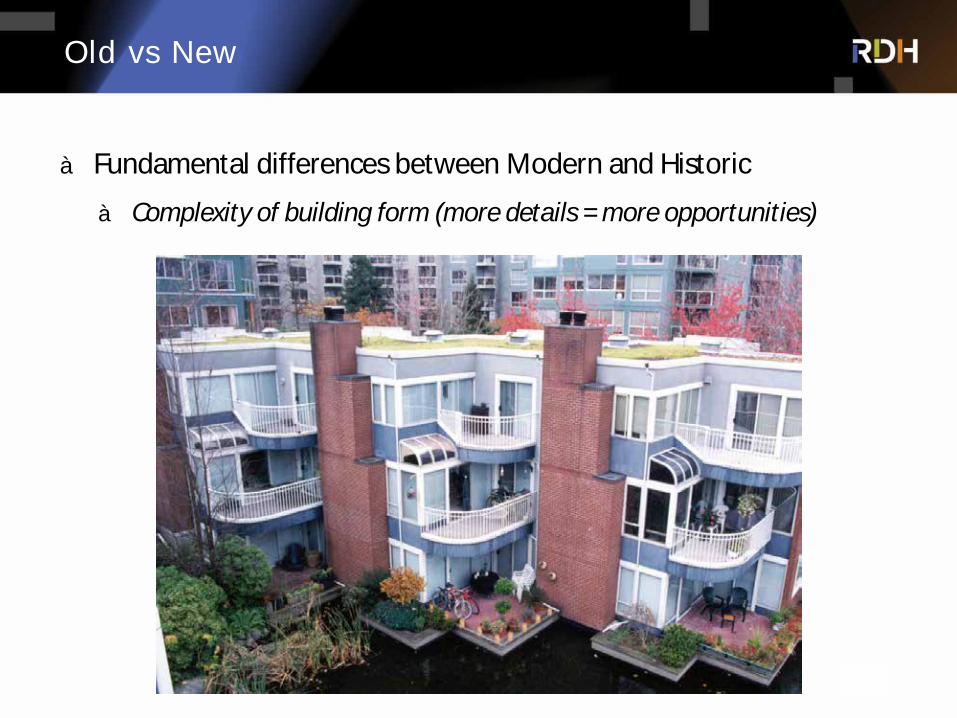
Old vs New
à Fundamental differences between Modern and Historic
à Complexity of building form (more details = more opportunities)
Modern Design Considerations
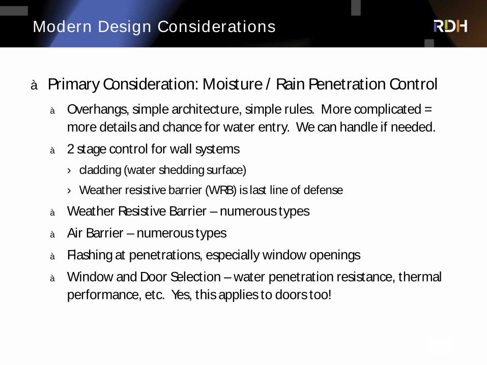
à Primary Consideration: Moisture / Rain Penetration Controlà Overhangs, simple architecture, simple rules. More complicated =
more details and chance for water entry. We can handle if needed.
à 2 stage control for wall systems› cladding (water shedding surface)
› Weather resistive barrier (WRB) is last line of defense
à Weather Resistive Barrier – numerous types
à Air Barrier – numerous types
à Flashing at penetrations, especially window openings
à Window and Door Selection – water penetration resistance, thermal performance, etc. Yes, this applies to doors too!
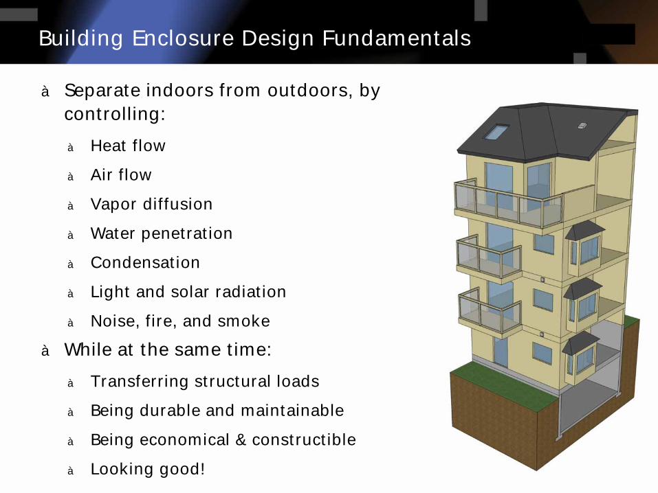
à Separate indoors from outdoors, by controlling:
à Heat flow
à Air flow
à Vapor diffusion
à Water penetration
à Condensation
à Light and solar radiation
à Noise, fire, and smoke
à While at the same time:
à Transferring structural loads
à Being durable and maintainable
à Being economical & constructible
à Looking good!
Building Enclosure Design Fundamentals
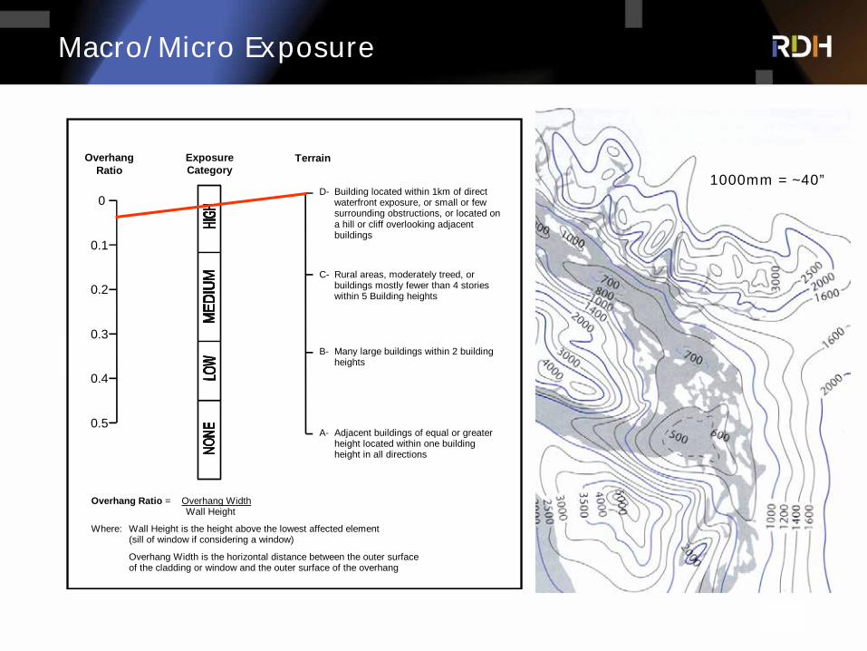
Macro/Micro Exposure
0
0.1
0.2
0.3
0.5
0.4
A- Adjacent buildings of equal or greater height located within one building height in all directions
B- Many large buildings within 2 building heights
C- Rural areas, moderately treed, or buildings mostly fewer than 4 stories within 5 Building heights
D- Building located within 1km of direct waterfront exposure, or small or few surrounding obstructions, or located on a hill or cliff overlooking adjacent buildings
Overhang Ratio
Exposure Category
Terrain
Overhang Ratio = Overhang Width Wall Height
Where: Wall Height is the height above the lowest affected element (sill of window if considering a window)
Overhang Width is the horizontal distance between the outer surface of the cladding or window and the outer surface of the overhang
1000mm = ~40”

Continuum of MC Strategies for Framed Walls
Concealed Barrier
Two lines of defenseSome drainage possibilities
Barrier or Face Sealed
One line of defense
Drained Cavity
Two lines of defenseClear drainage
Rainscreen
Two lines of defenseClear drainageGood air barrier
Two lines of defenseClear drainageGood air barrierCompartmentalization
P. M. Rainscreen
Opportunity for Drainage and Ventilation Drying
Faith-based Moisture Control

à “Standard Approach” to Below Water Table Waterproofing
à Positive/Negative Side
à Damp proofing
Below Grade Waterproofing
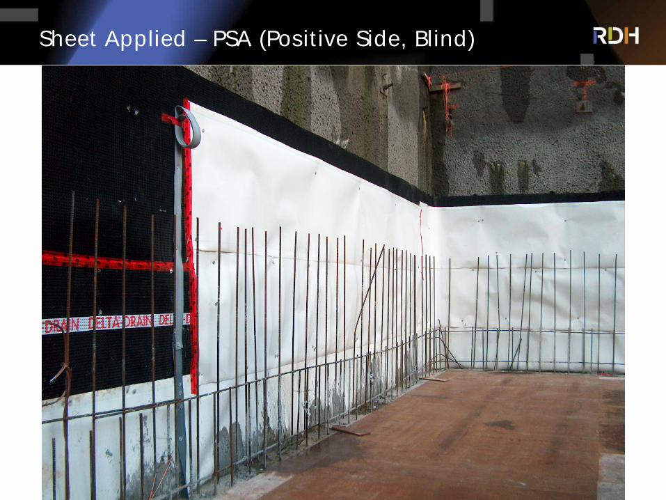
Sheet Applied – PSA (Positive Side, Blind)
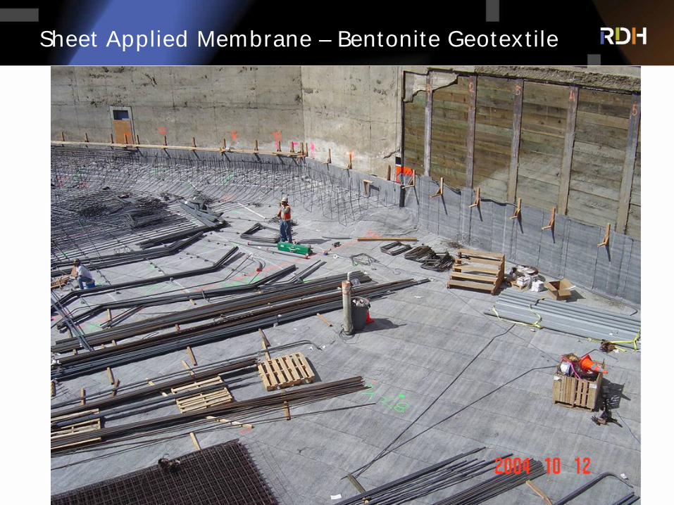
Sheet Applied Membrane – Bentonite Geotextile
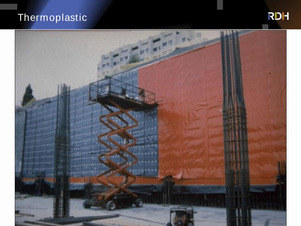
Thermoplastic
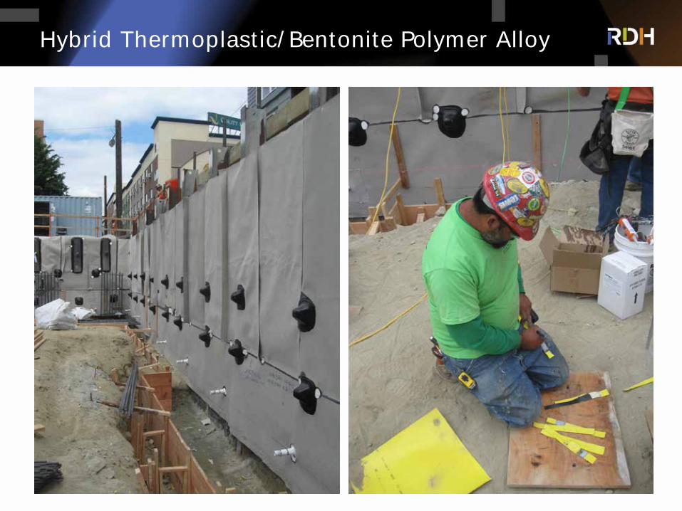
Hybrid Thermoplastic/Bentonite Polymer Alloy
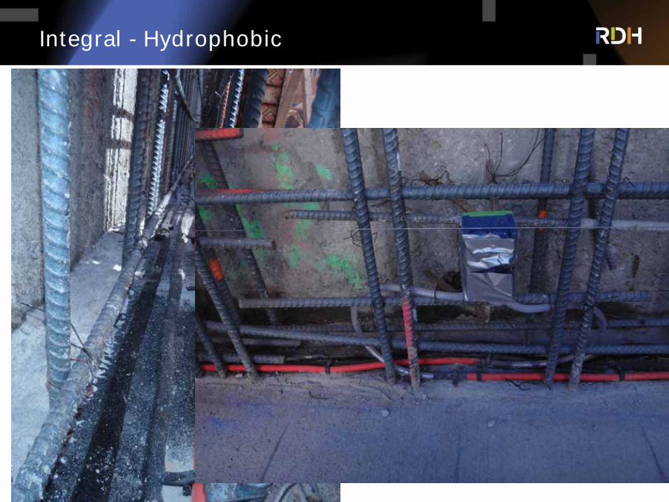
Integral - Hydrophobic
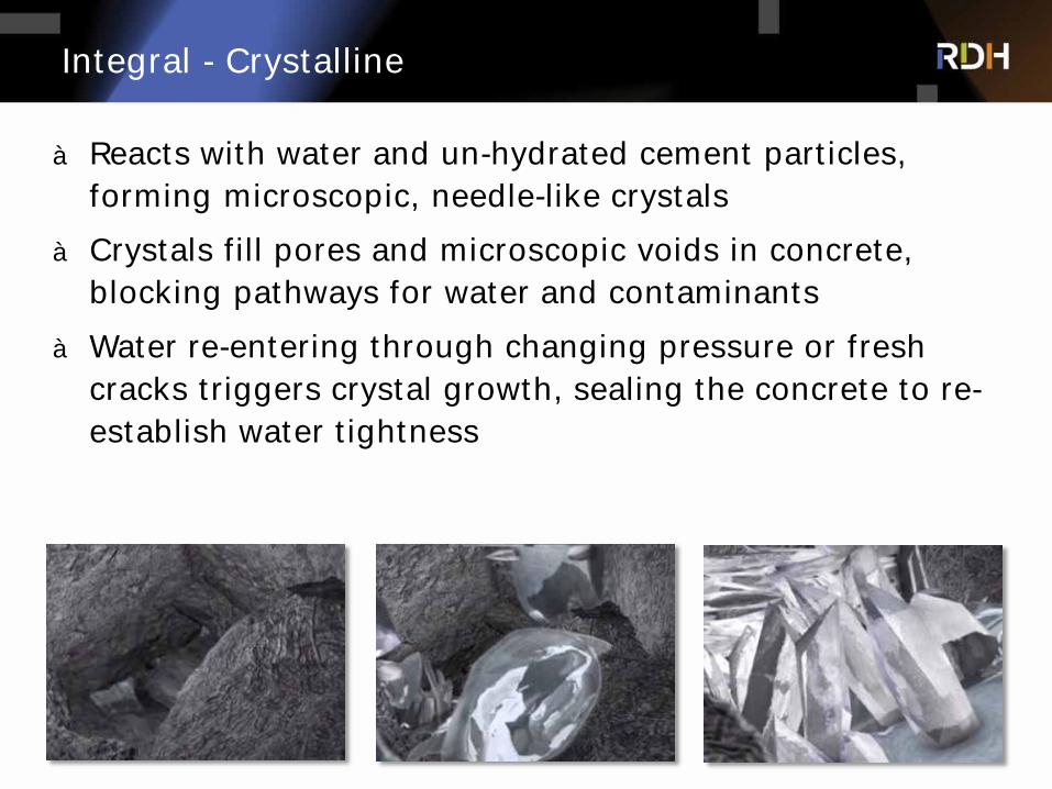
Integral - Crystalline
à Reacts with water and un-hydrated cement particles, forming microscopic, needle-like crystals
à Crystals fill pores and microscopic voids in concrete, blocking pathways for water and contaminants
à Water re-entering through changing pressure or fresh cracks triggers crystal growth, sealing the concrete to re-establish water tightness
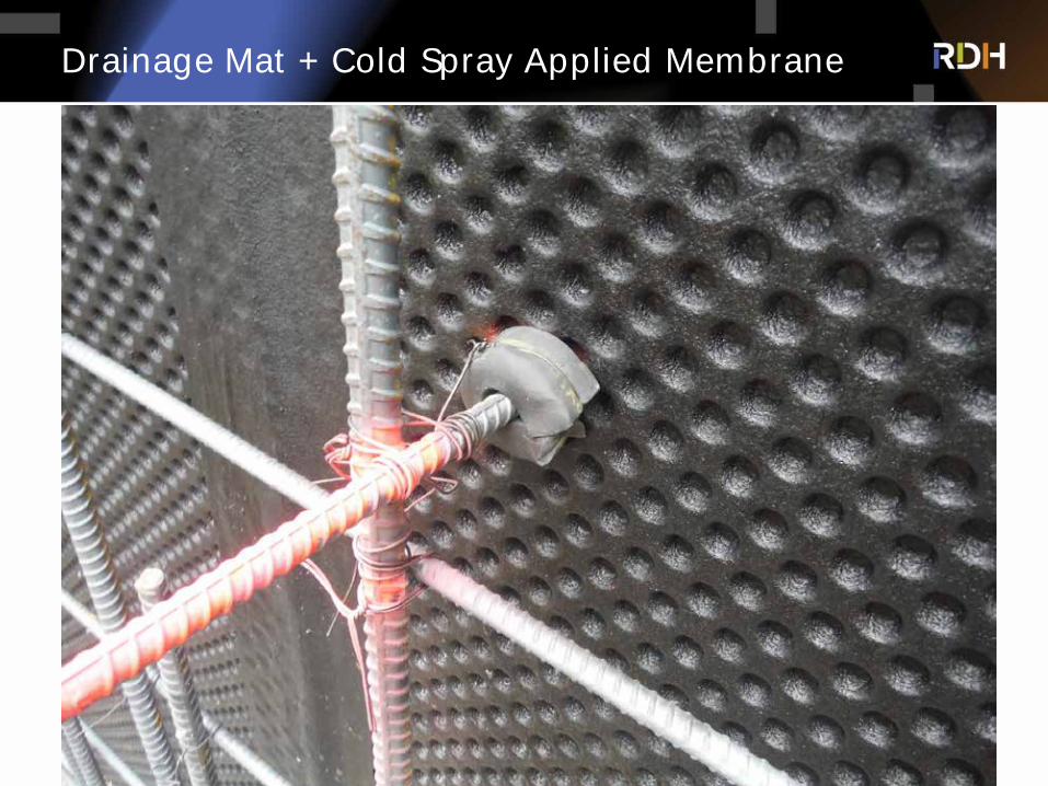
Drainage Mat + Cold Spray Applied Membrane

Drainage Mat
à Wood shrinkage/Brick Growth
à Floor lines
à Windows
à Balconies
Design for Wood-Movement & Shrinkage
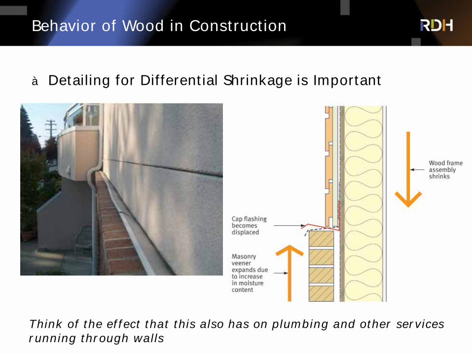
Behavior of Wood in Construction
à Detailing for Differential Shrinkage is Important
Think of the effect that this also has on plumbing and other services running through walls
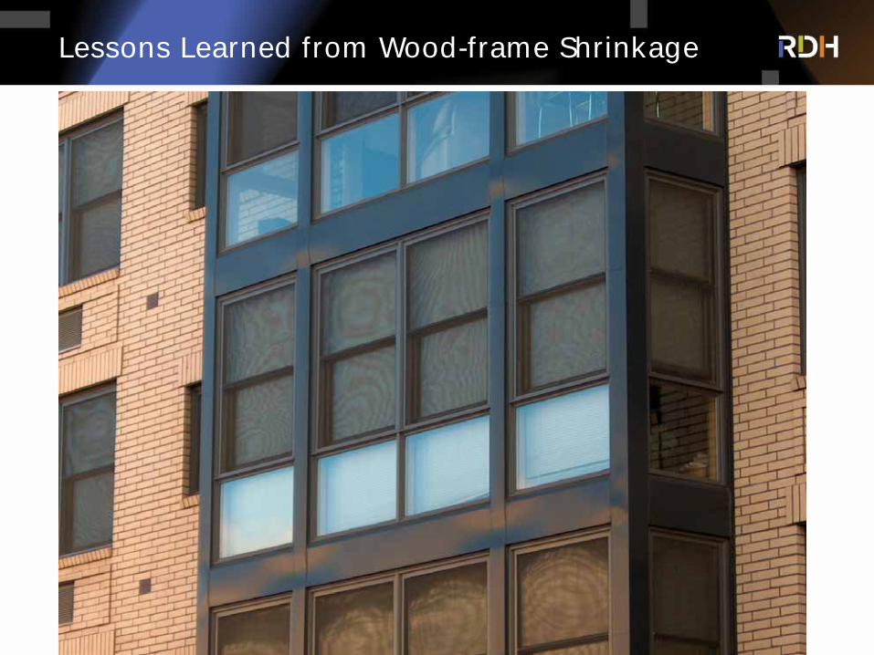
Lessons Learned from Wood-frame Shrinkage
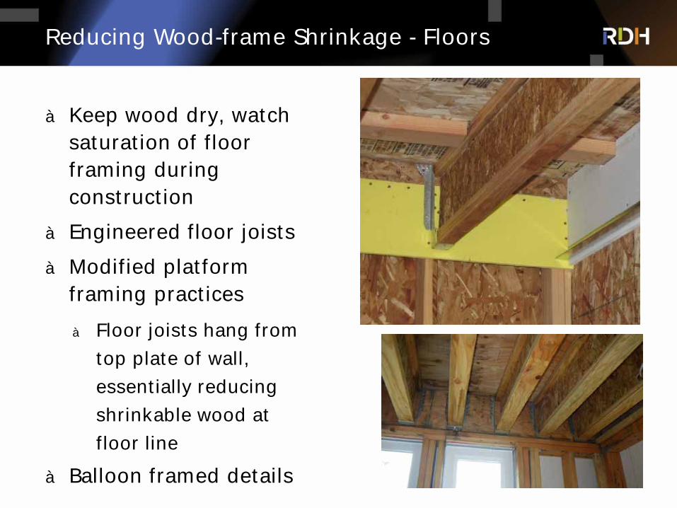
Reducing Wood-frame Shrinkage - Floors
à Keep wood dry, watch saturation of floor framing during construction
à Engineered floor joists
à Modified platform framing practices
à Floor joists hang from
top plate of wall,
essentially reducing
shrinkable wood at
floor line
à Balloon framed details
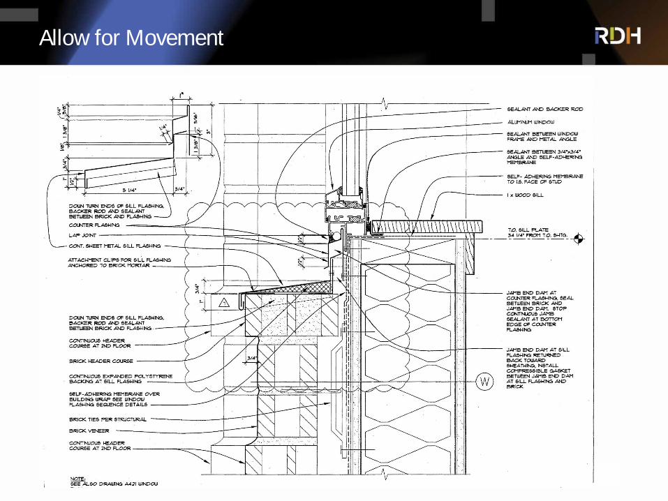
Allow for Movement
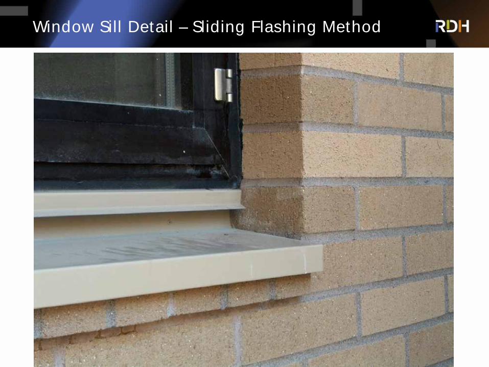
Window Sill Detail – Sliding Flashing Method
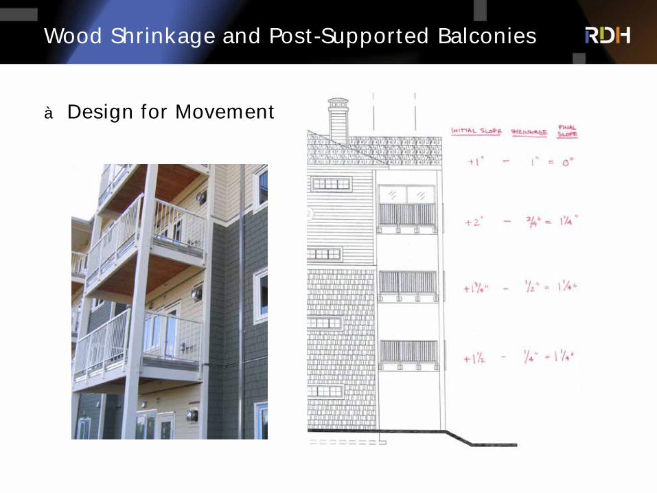
Wood Shrinkage and Post-Supported Balconies
à Design for Movement

Air and Weather Barrier Detailing for Taller Wood Buildings

Impact – Increase in Wind & Rain Loads
à Increase in height generally means higher wind loads (in the order of 10%), and increased rain deposition
à Other factors just as significant
à Proximity to open water
à Sloped site
à Local terrain
à Air barrier/Weather barrier
à Exterior sheathing membrane
à Exterior sheathing
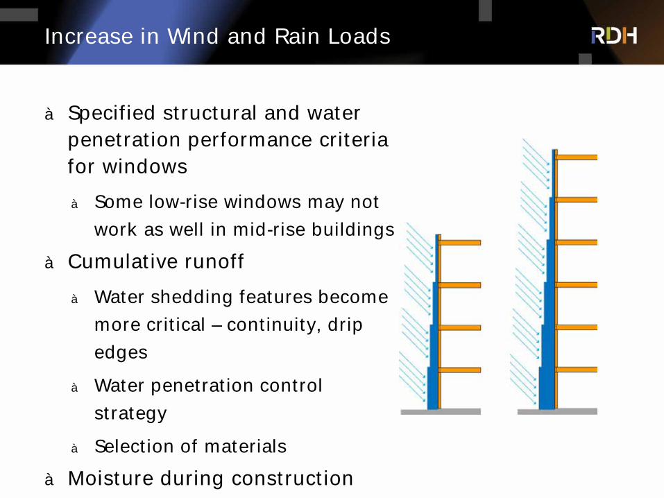
Increase in Wind and Rain Loads
à Specified structural and water penetration performance criteria for windows
à Some low-rise windows may not
work as well in mid-rise buildings
à Cumulative runoff
à Water shedding features become
more critical – continuity, drip
edges
à Water penetration control
strategy
à Selection of materials
à Moisture during construction
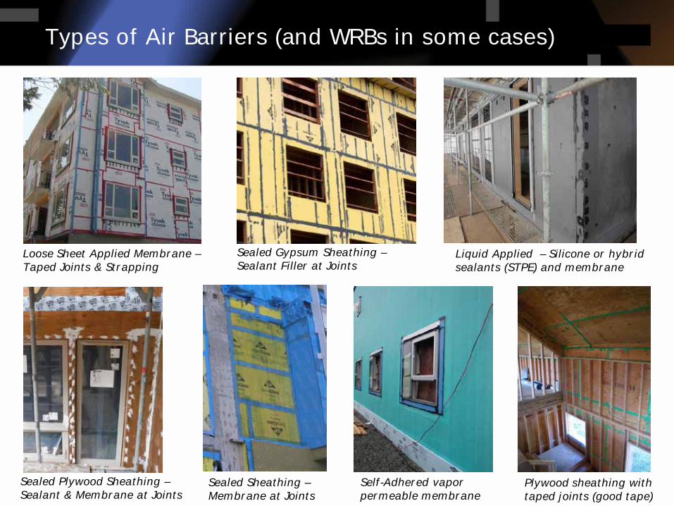
Types of Air Barriers (and WRBs in some cases)
Sealed Gypsum Sheathing –Sealant Filler at Joints
Loose Sheet Applied Membrane –Taped Joints & Strapping
Liquid Applied – Silicone or hybrid sealants (STPE) and membrane
Sealed Plywood Sheathing –Sealant & Membrane at Joints
Sealed Sheathing –Membrane at Joints
Self-Adhered vapor permeable membrane
Plywood sheathing with taped joints (good tape)
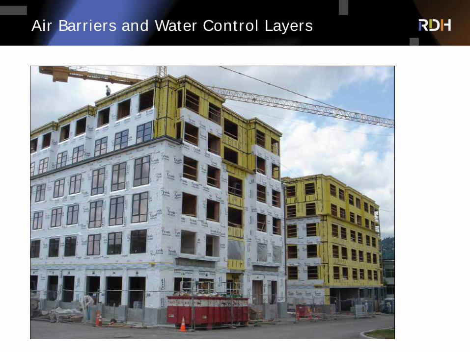
Air Barriers and Water Control Layers

Airtightness Does Not Happen By Accident

Air Barrier Details
à Pre-stripping AB membrane is often recommended at balconies and roof-wall transitions – but often forgotten!
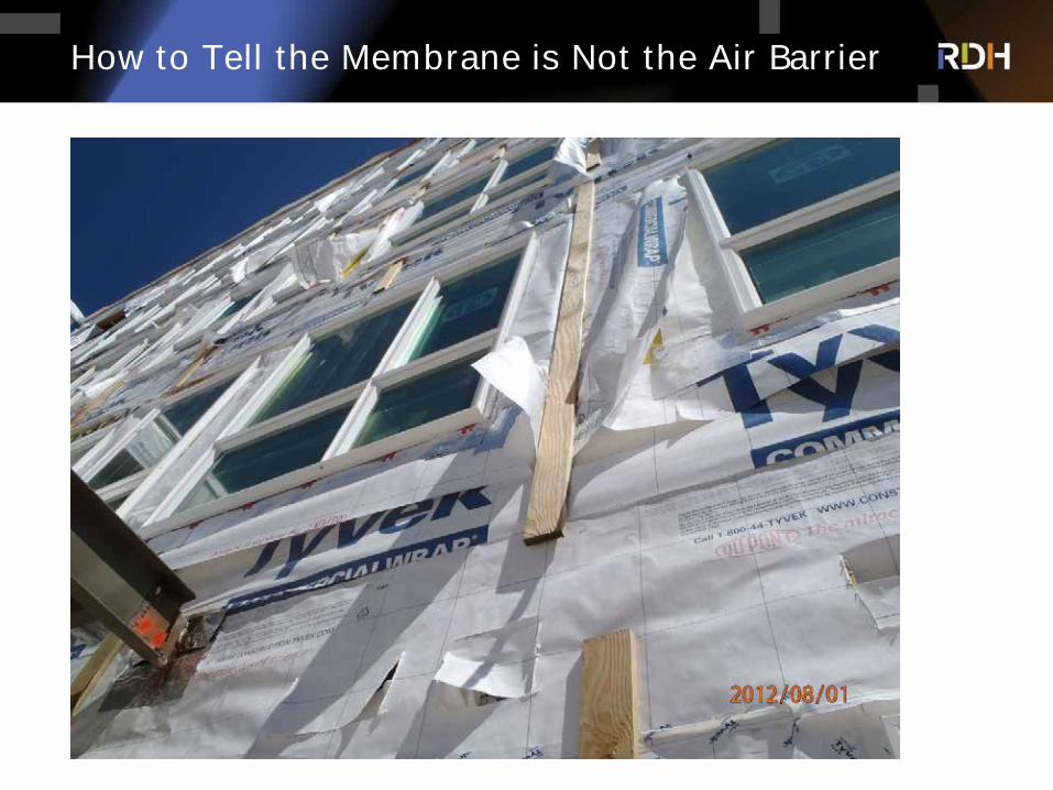
How to Tell the Membrane is Not the Air Barrier

à Windows
Air/Moisture Barrier Detailing
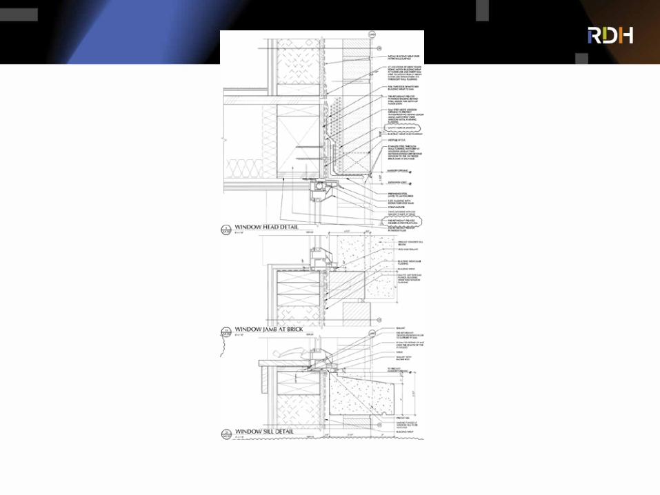
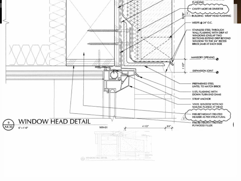
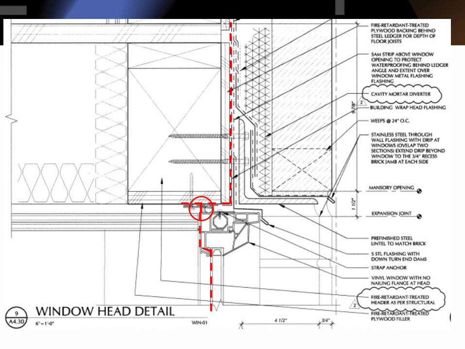


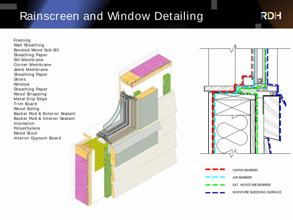
Rainscreen and Window Detailing
FramingWall SheathingBeveled Wood Sub-SillSheathing PaperSill MembraneCorner MembraneJamb MembraneSheathing PaperShims
Sheathing PaperWood Strapping
Backer Rod & Interior SealantInsulation
Interior Gypsum Board
PolyethyleneWood Stool
Wood Siding
Metal Drip EdgeTrim Board
Backer Rod & Exterior Sealant
Window
VAPOR BARRIERVAPOUR BARRIER
AIR BARRIERAIR BARRIER
VAPOUR BARRIER
EXT. MOISTURE BARRIER
AIR BARRIER
VAPOR BARRIER
EXT. MOISTURE BARRIER
MOISTURE SHEDDING SURFACE
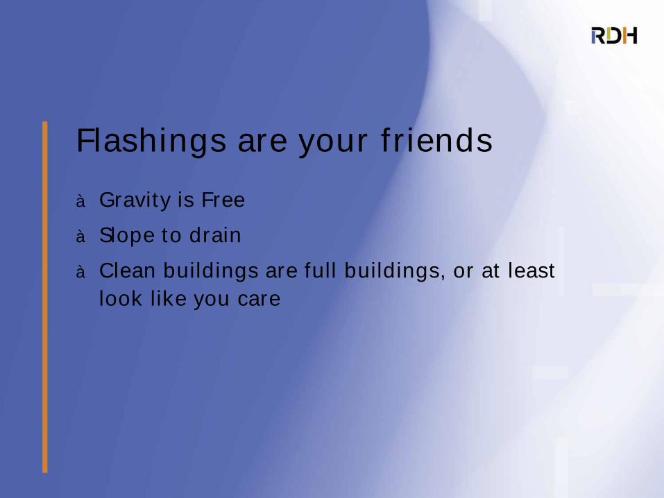
à Gravity is Free
à Slope to drain
à Clean buildings are full buildings, or at least look like you care
Flashings are your friends
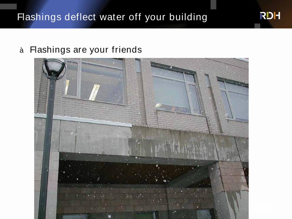
Flashings deflect water off your building
à Flashings are your friends
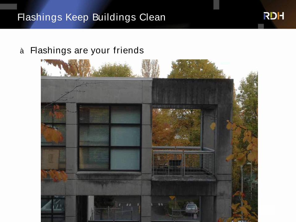
Flashings Keep Buildings Clean
à Flashings are your friends
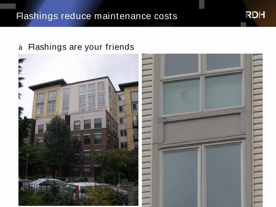
Flashings reduce maintenance costs
à Flashings are your friends
The Future of Insulation: Hybrid Insulation/Split Insulated Assemblies
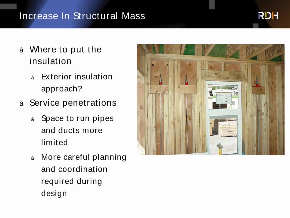
Increase In Structural Mass
à Where to put the insulation
à Exterior insulation
approach?
à Service penetrations
à Space to run pipes
and ducts more
limited
à More careful planning
and coordination
required during
design
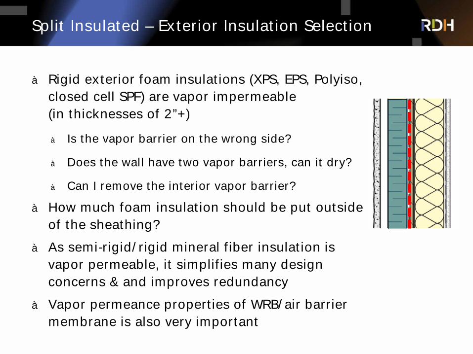
Split Insulated – Exterior Insulation Selection
à Rigid exterior foam insulations (XPS, EPS, Polyiso, closed cell SPF) are vapor impermeable (in thicknesses of 2”+)
à Is the vapor barrier on the wrong side?
à Does the wall have two vapor barriers, can it dry?
à Can I remove the interior vapor barrier?
à How much foam insulation should be put outside of the sheathing?
à As semi-rigid/rigid mineral fiber insulation is vapor permeable, it simplifies many design concerns & and improves redundancy
à Vapor permeance properties of WRB/air barrier membrane is also very important
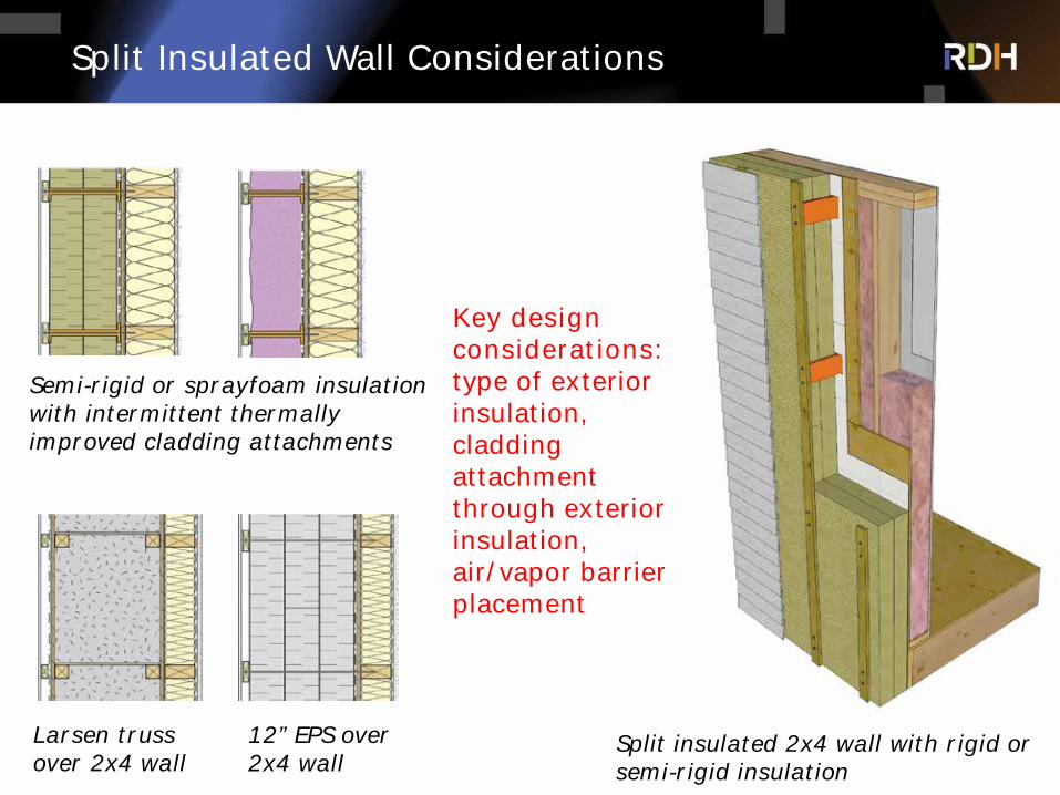
Split Insulated Wall Considerations
Semi-rigid or sprayfoam insulation with intermittent thermally improved cladding attachments
Larsen truss over 2x4 wall
12” EPS over 2x4 wall
Key design considerations: type of exterior insulation, cladding attachment through exterior insulation, air/vapor barrier placement
Split insulated 2x4 wall with rigid or semi-rigid insulation
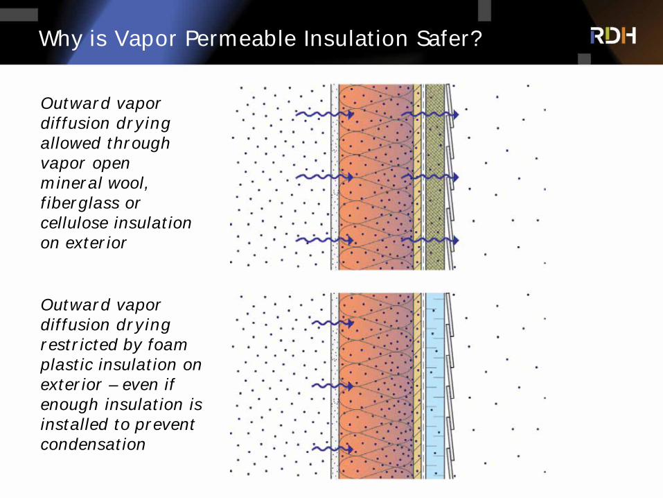
Why is Vapor Permeable Insulation Safer?
Outward vapor diffusion dryingallowed through vapor open mineral wool, fiberglass or cellulose insulation on exterior
Outward vapor diffusion dryingrestricted by foam plastic insulation on exterior – even if enough insulation is installed to prevent condensation
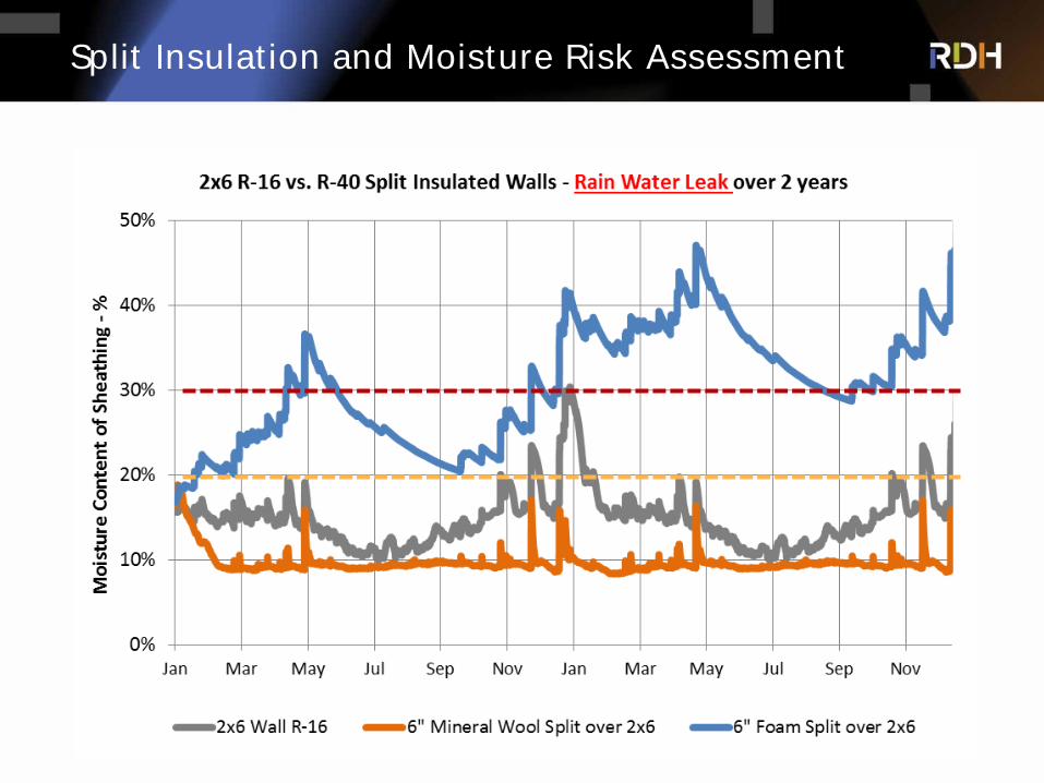
Split Insulation and Moisture Risk Assessment
Insulation Ratio Here is over 2/3 to the exterior of the sheathingCareful with lower ratios with foam
Exterior Insulation & Cladding Attachment Considerations
à Cladding weight & gravity loads
à Wind loads
à Seismic loads
à Back-up wall construction (wood, concrete, steel)
à Attachment from clip/girt back into structure (studs, sheathing,
or slab edge)
à Exterior insulation thickness
à Rigid vs semi-rigid insulation
à R-value target, tolerable thermal loss?
à Ease of attachment of cladding – returns, corners
à Combustibility requirements
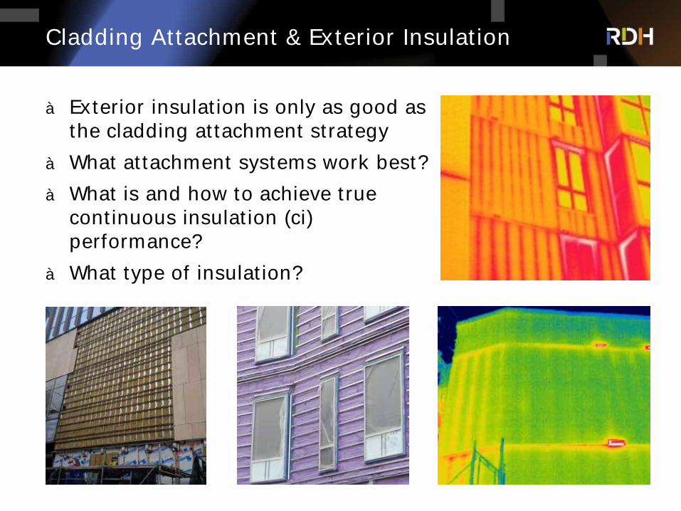
Cladding Attachment & Exterior Insulation
à Exterior insulation is only as good as the cladding attachment strategy
à What attachment systems work best?
à What is and how to achieve true continuous insulation (ci) performance?
à What type of insulation?

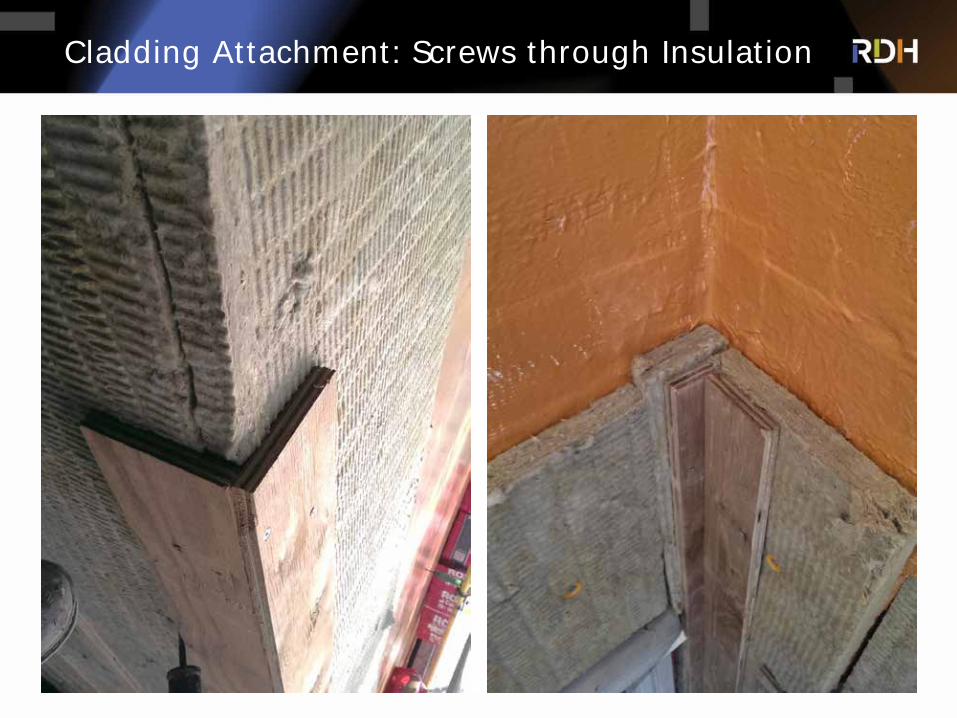
Cladding Attachment: Screws through Insulation
Longer cladding Fasteners directly through rigid insulation (up to 2” for light claddings)
Long screws through vertical strapping and rigid insulation creates truss – short cladding fasteners into vertical strapping Rigid shear block type connection
through insulation, short cladding fasteners into vertical strapping
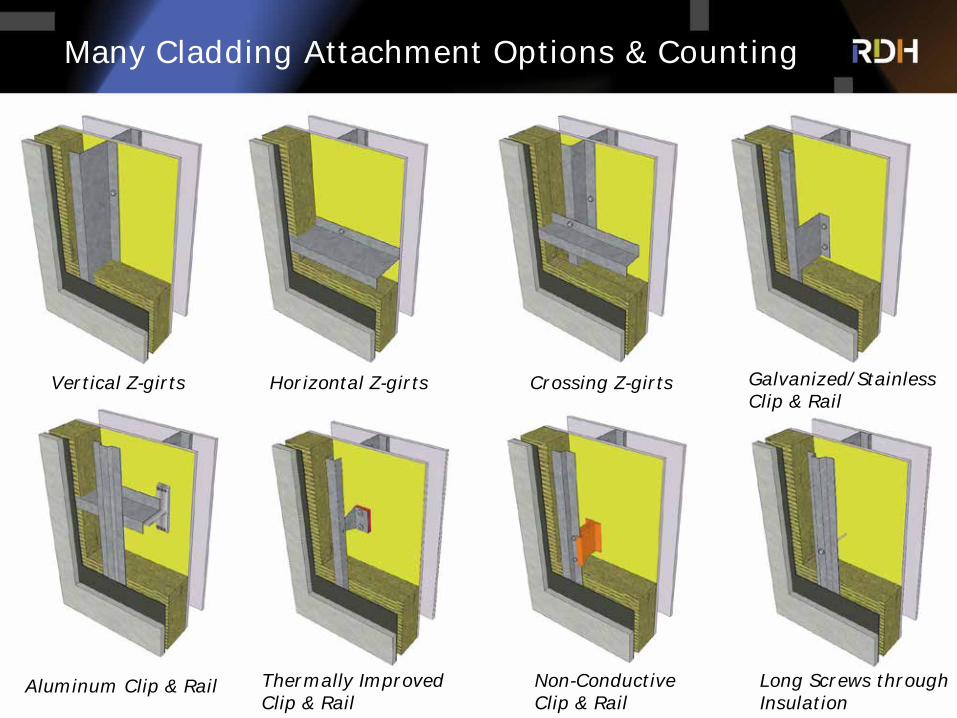
Many Cladding Attachment Options & Counting
Vertical Z-girts Horizontal Z-girts Crossing Z-girts Galvanized/Stainless Clip & Rail
Thermally Improved Clip & Rail
Aluminum Clip & Rail Non-Conductive Clip & Rail
Long Screws through Insulation
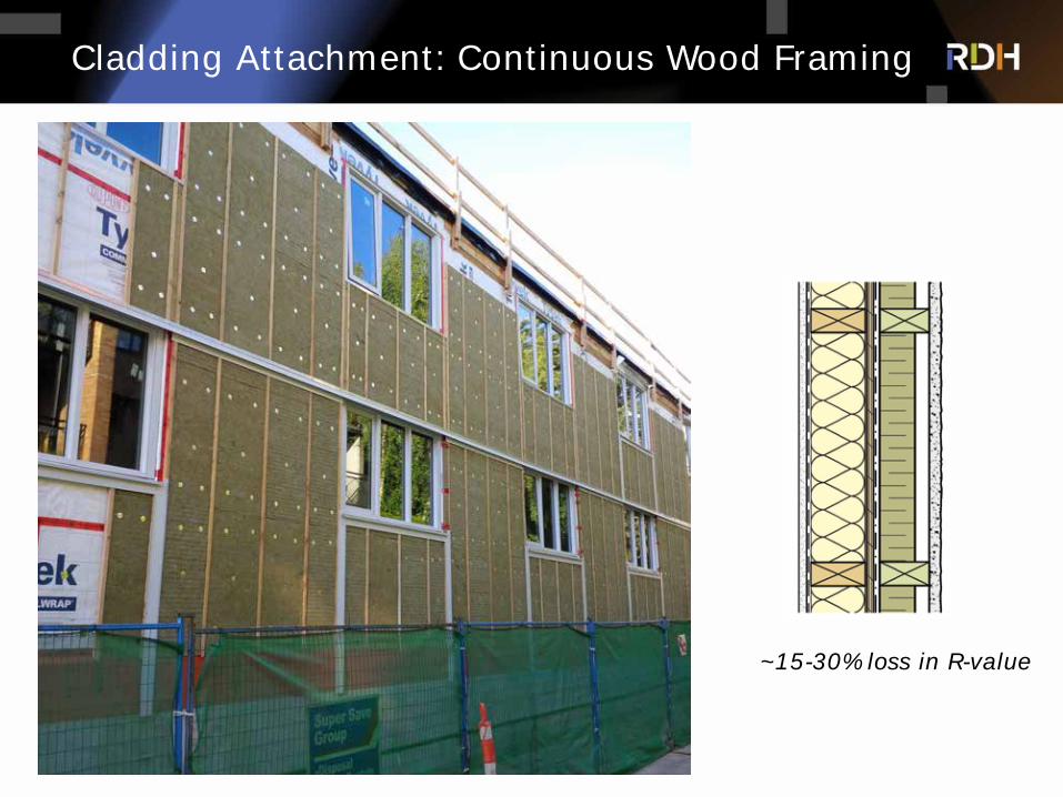
Cladding Attachment: Continuous Wood Framing
~15-30% loss in R-value
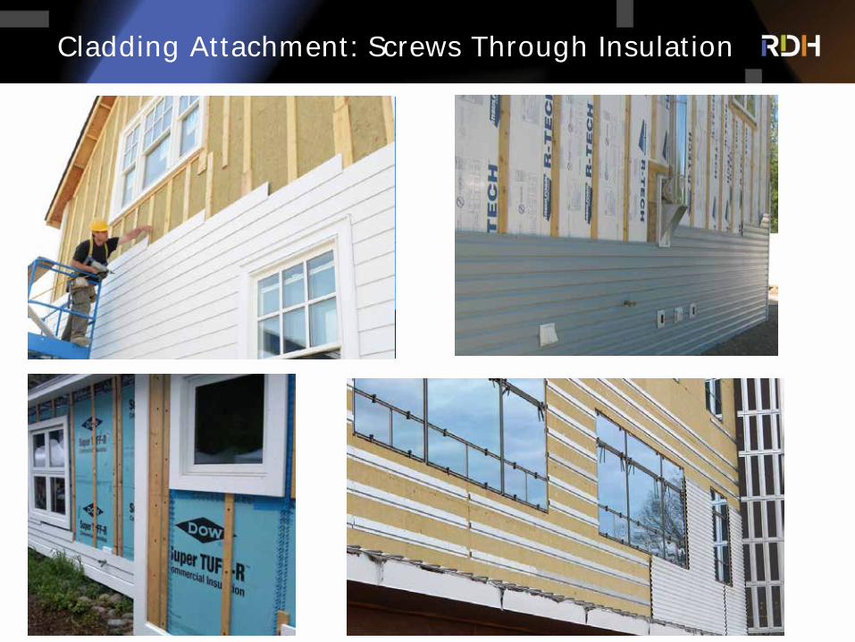
Cladding Attachment: Screws Through Insulation
Cladding Attachment: Screws through Insulation
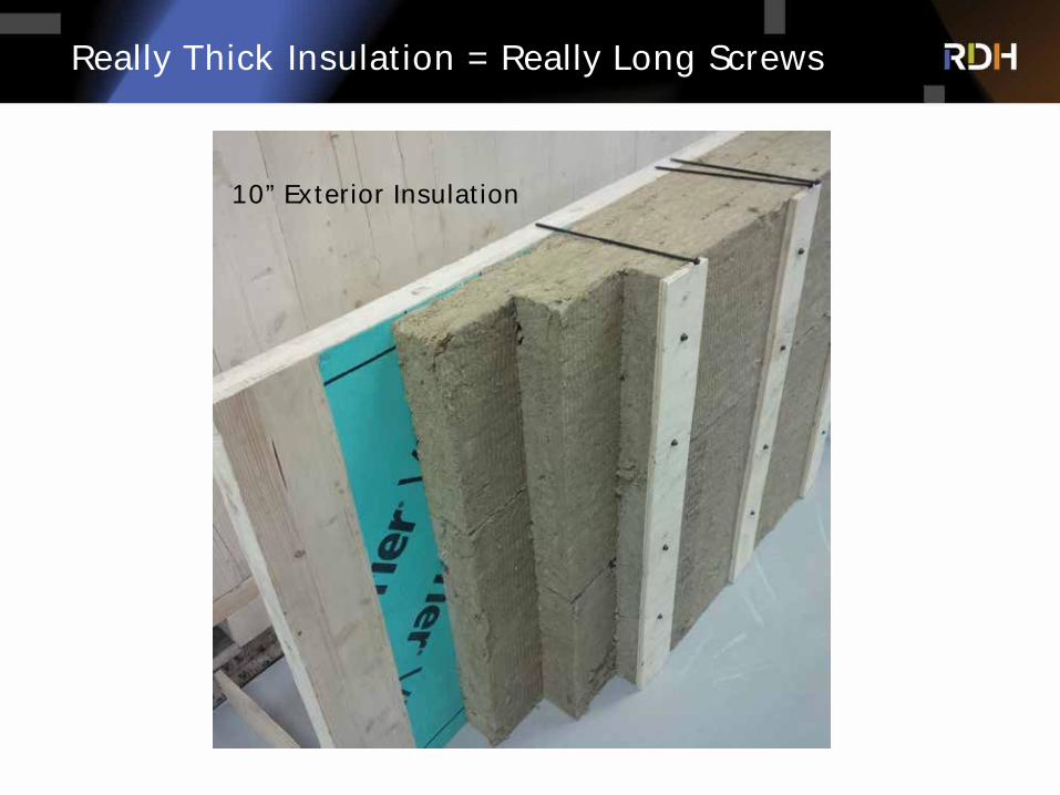
Really Thick Insulation = Really Long Screws
10” Exterior Insulation
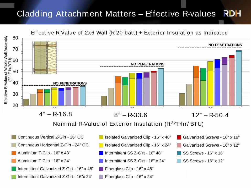
Cladding Attachment Matters – Effective R-values
20
30
40
50
60
70
80
16.8 33.6 50.4
Effe
ctiv
e R
-Val
ue o
f Who
le W
all A
ssem
bly
(ft2 ·
°F·h
r/BTU
)
NO PENETRATIONS
NO PENETRATIONS
NO PENETRATIONS
Nominal R-Value of Exterior Insulation (ft2·°F·hr/BTU)
4” – R-16.8 8” – R-33.6 12” – R-50.4
Continuous Vertical Z-Girt - 16" OC
Continuous Horizontal Z-Girt - 24" OC
Aluminium T-Clip - 16" x 48"
Aluminium T-Clip - 16" x 24"
Intermittent Galvanized Z-Girt - 16" x 48"
Intermittent Galvanized Z-Girt - 16"x 24"
Isolated Galvanized Clip - 16" x 48"
Isolated Galvanized Clip - 16" x 24"
Intermittent SS Z-Girt - 16" 48"
Intermittent SS Z-Girt - 16" x 24"
Fiberglass Clip - 16" x 48"
Fiberglass Clip - 16" x 24"
Galvanized Screws - 16" x 16"
Galvanized Screws - 16" x 12"
SS Screws - 16" x 16"
SS Screws - 16" x 12"
Effective R-Value of 2x6 Wall (R-20 batt) + Exterior Insulation as Indicated

Balcony Designs
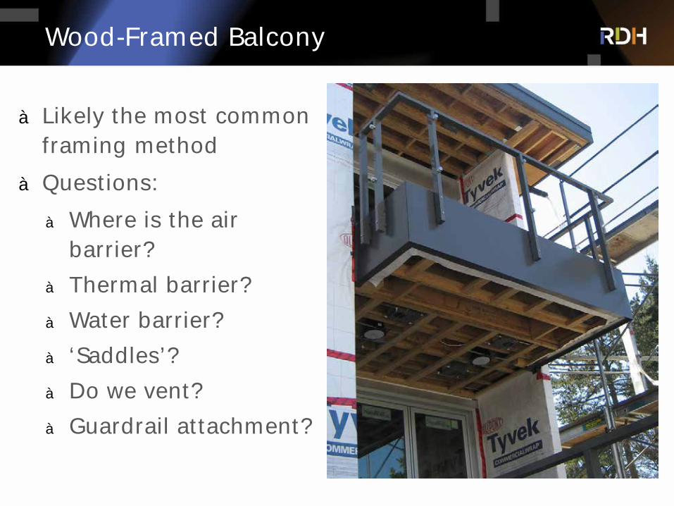
Wood-Framed Balcony
à Likely the most common framing method
à Questions:
à Where is the air barrier?
à Thermal barrier?
à Water barrier?
à ‘Saddles’?
à Do we vent?
à Guardrail attachment?
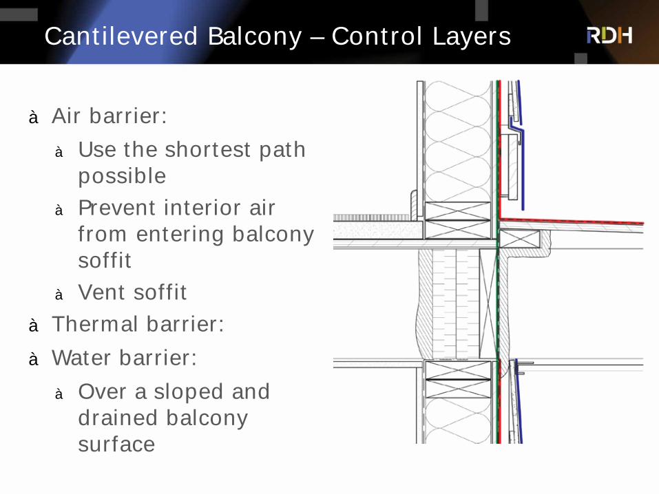
Cantilevered Balcony – Control Layers
à Air barrier:
à Use the shortest path possible
à Prevent interior air from entering balcony soffit
à Vent soffit
à Thermal barrier:
à Water barrier:
à Over a sloped and drained balcony surface
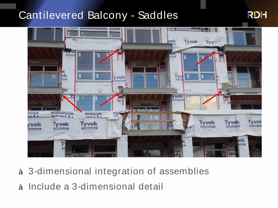
Cantilevered Balcony - Saddles
à 3-dimensional integration of assemblies
à Include a 3-dimensional detail
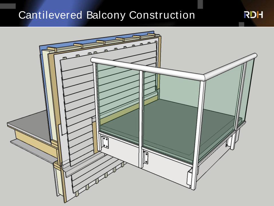
Cantilevered Balcony Construction

Pre-Finished Steel Balcony over Wood
à ‘Bolt-on’ architectural component, but not part of building enclosure
à Air, water, and thermal control layers continuous behind pre-finished balcony
à Simplifies detailing – no saddles
à Use durable materials
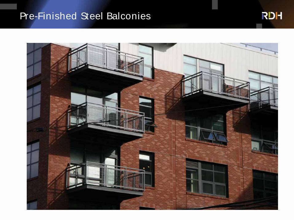
Pre-Finished Steel Balconies
à Ventilated roofs aren’t what they used to be.
Roof Designs

Roof Design for Larger Wood Buildings
à Key Considerations: Keep dry, allow to dry,
robustness of assemblies, sloping strategy
à Strategies:
à Protect wood roof from getting wet during
construction
à Insulation on top of air and vapor control layers -
conventional or protected membrane assemblies
à Connect control layers at walls
à Be cautious of interior insulated
approaches, with or without venting
à Membrane color matters, but maybe not in
the way that you think
Conventional roof with tapered insulation over wood joists
Protected membrane roof over vented & tapered structure over CLT

Attics & Vented Roofs – Control Layers
à Likely the most common assembly in USA for sloped roofs – good track record in most climates
à Be cautious if used on low-slope roofs, particularly if venting path is complicated
à Air barrier continuity at ceiling and roof-to-wall is critical
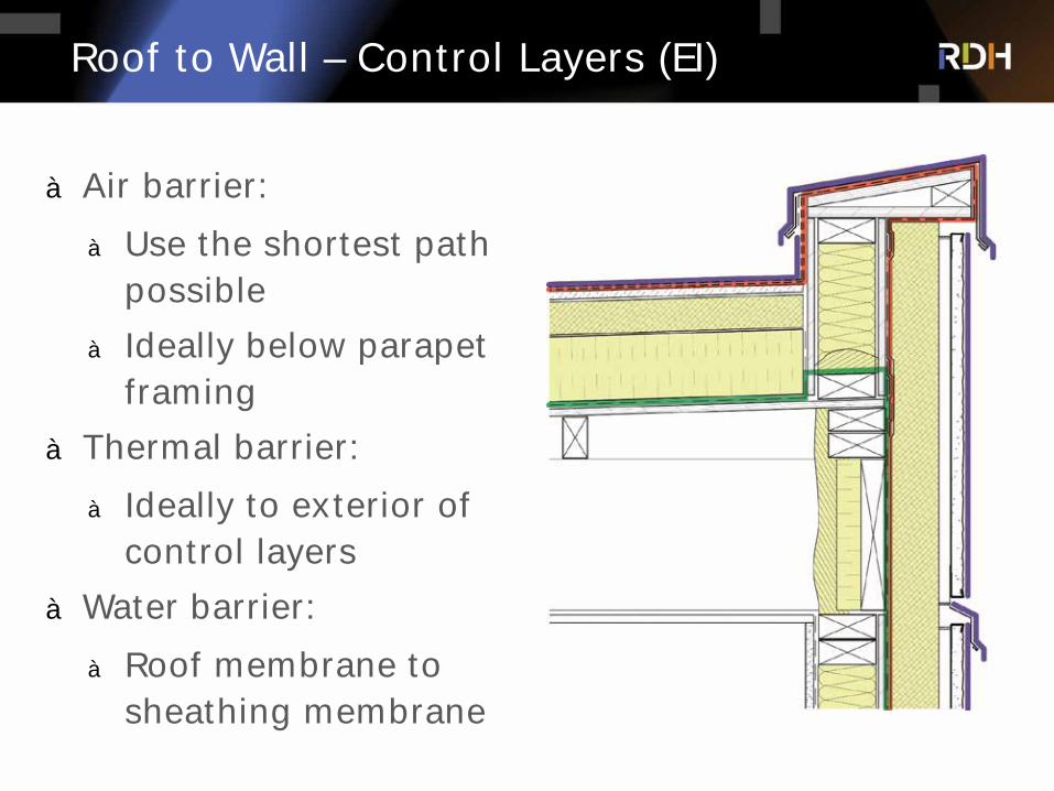
Roof to Wall – Control Layers (EI)
à Air barrier:
à Use the shortest path possible
à Ideally below parapet framing
à Thermal barrier:
à Ideally to exterior of control layers
à Water barrier:
à Roof membrane to sheathing membrane
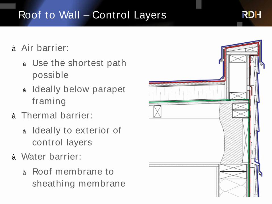
Roof to Wall – Control Layers
à Air barrier:
à Use the shortest path possible
à Ideally below parapet framing
à Thermal barrier:
à Ideally to exterior of control layers
à Water barrier:
à Roof membrane to sheathing membrane
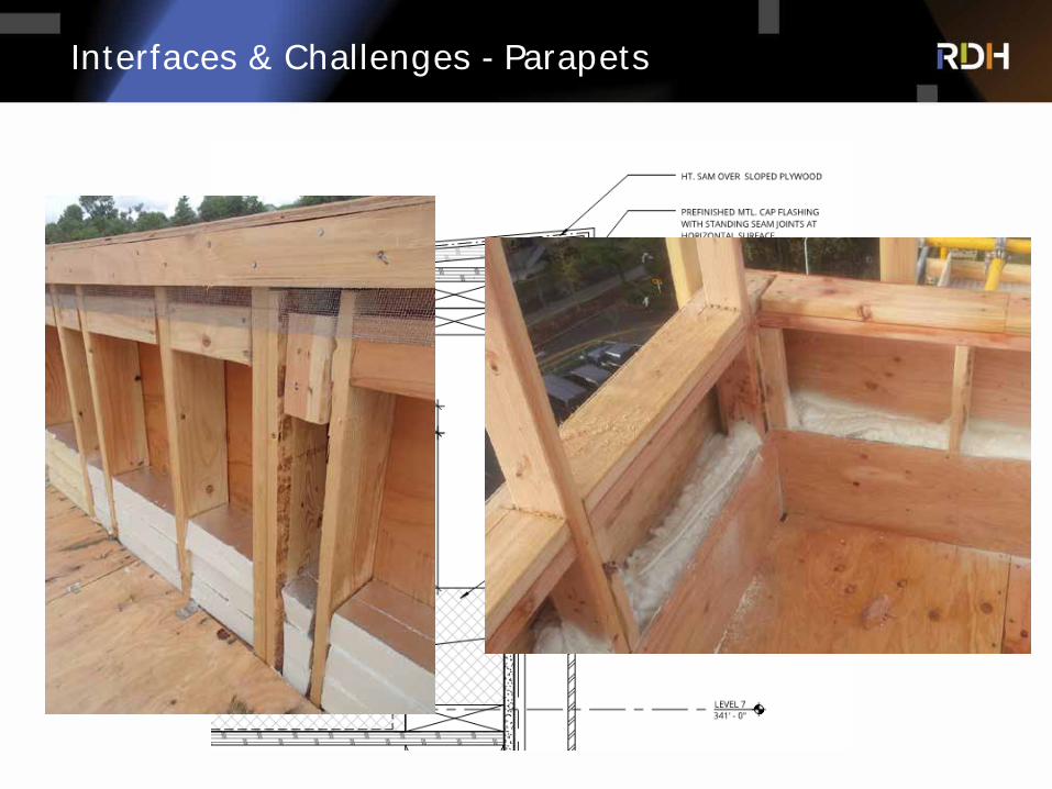
Interfaces & Challenges - Parapets
Summary
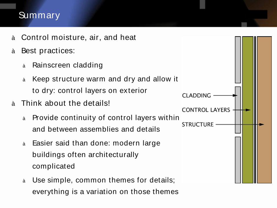
à Control moisture, air, and heat
à Best practices:
à Rainscreen cladding
à Keep structure warm and dry and allow it
to dry: control layers on exterior
à Think about the details!
à Provide continuity of control layers within
and between assemblies and details
à Easier said than done: modern large
buildings often architecturally
complicated
à Use simple, common themes for details;
everything is a variation on those themes
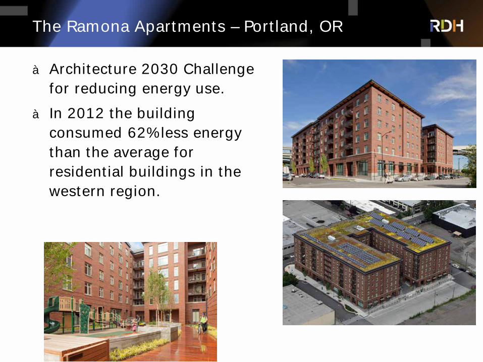
à Architecture 2030 Challenge for reducing energy use.
à In 2012 the building consumed 62% less energy than the average for residential buildings in the western region.
The Ramona Apartments – Portland, OR

The Ramona – Air Barrier Construction
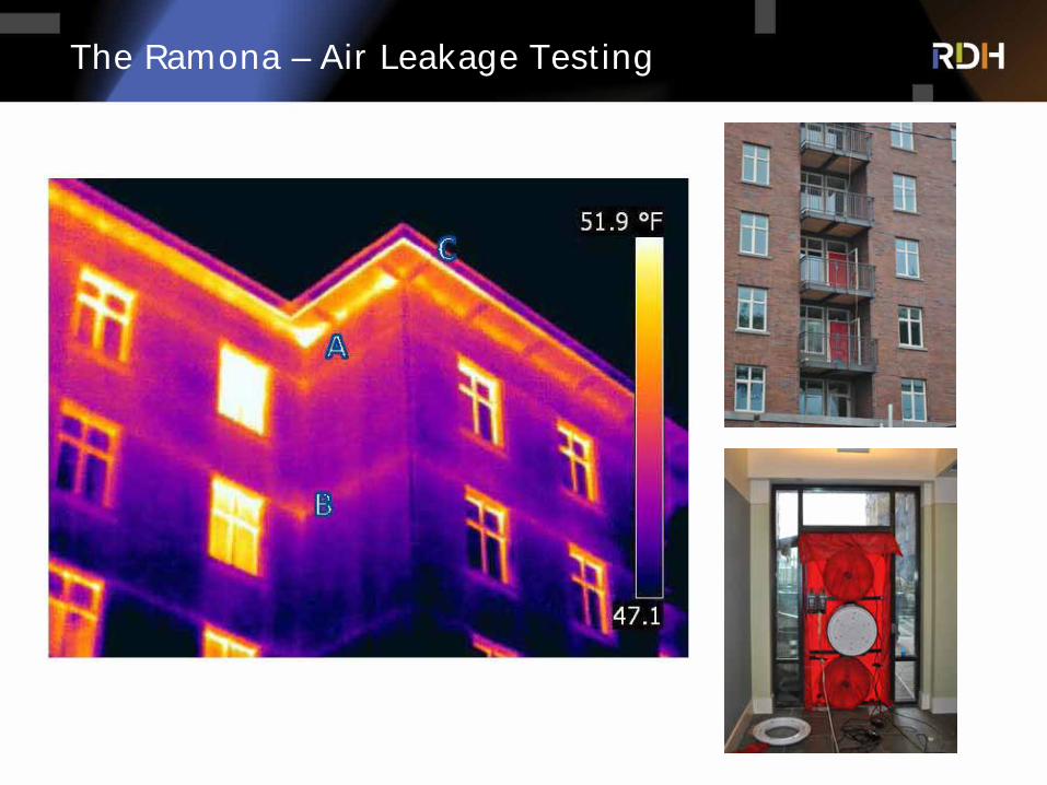
The Ramona – Air Leakage Testing
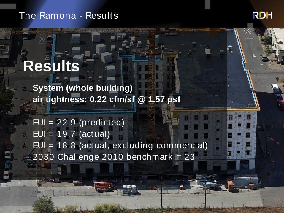
The Ramona - Results
Resultsà System (whole building)
air tightness: 0.22 cfm/sf @ 1.57 psf
à EUI = 22.9 (predicted)à EUI = 19.7 (actual)à EUI = 18.8 (actual, excluding commercial)à 2030 Challenge 2010 benchmark = 23

à rdh.com
Discussion + Questions
FOR FURTHER INFORMATION PLEASE VISIT

![Premier Marine Q-Portal · 2017-03-30 · Concrete Block I Masonry Wood Siding - Wood Frame [l Stone Veneer - Wood Frame C] Foundation: Concrete [X Year Built: 1960 Stucco Wood Frame](https://img.pdfslide.net/doc/110x75/5f9385ea1c2ce46d26753432/premier-marine-q-portal-2017-03-30-concrete-block-i-masonry-wood-siding-wood.jpg)