Embed Size (px)
Citation preview
1
flowserve.com
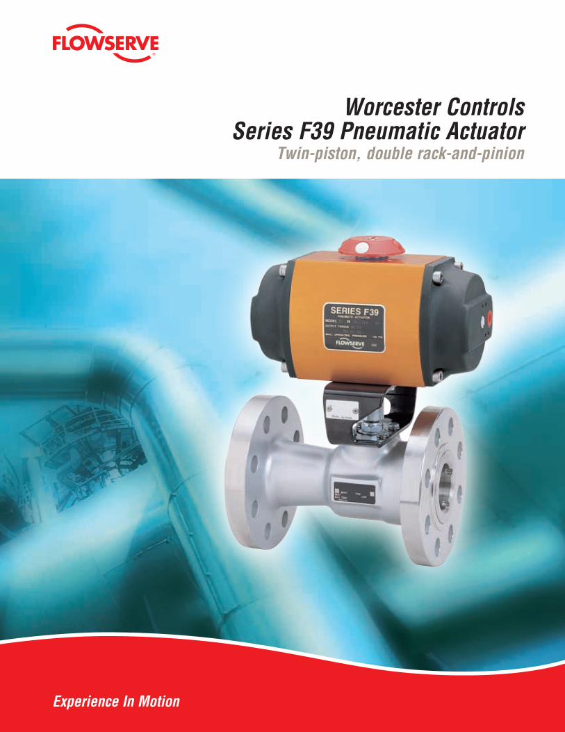
Worcester Controls Series F39 Pneumatic Actuator
Twin-piston, double rack-and-pinion
Experience In Motion
2
Features and Benefits
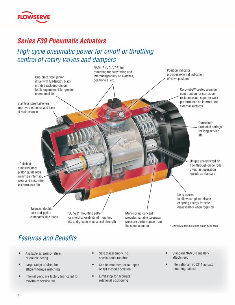
Series F39 Pneumatic Actuators
High cycle pneumatic power for on/off or throttling control of rotary valves and dampers
* Size 05F39 does not utilize piston guide rods.
Stainless steel fasteners improve aesthetics and ease of maintenance
One-piece steel pinion drive with full-length, black nitrided rack-and-pinion tooth engagement for greater operational life
Balanced double rack-and-pinion eliminates side loads
ISO 5211 mounting patternfor interchangeability of mounting kits and greater mechanical strength
Long screwsto allow complete release of spring energy for safe disassembly when required
Multi-spring conceptprovides variable torque/air pressure performance from the same actuator
Corrosion-protected springs for long service life
Position indicator provides external indication of valve position
NAMUR (VDI/VDE) top mounting for easy fitting and interchangeability of switches, positioners, etc.
Coro-lube™ coated aluminum construction for corrosion resistance and superior wear performance on internal and external surfaces
*Polished stainless steel piston guide rods minimize internal wear and maximize performance life
Unique unrestricted air flow through guide rods gives fast operation speeds as standard
• Available as spring-return or double-acting
• Large range of sizes for efficient torque matching
• Internal parts are factory lubricated for maximum service life
• Safe disassembly, no special tools required
• Can be mounted for fail-open or fail-closed operation
• Limit stop for accurate rotational positioning
• Standard NAMUR ancillary attachment
• International ISO5211 actuator mounting pattern
3
flowserve.com
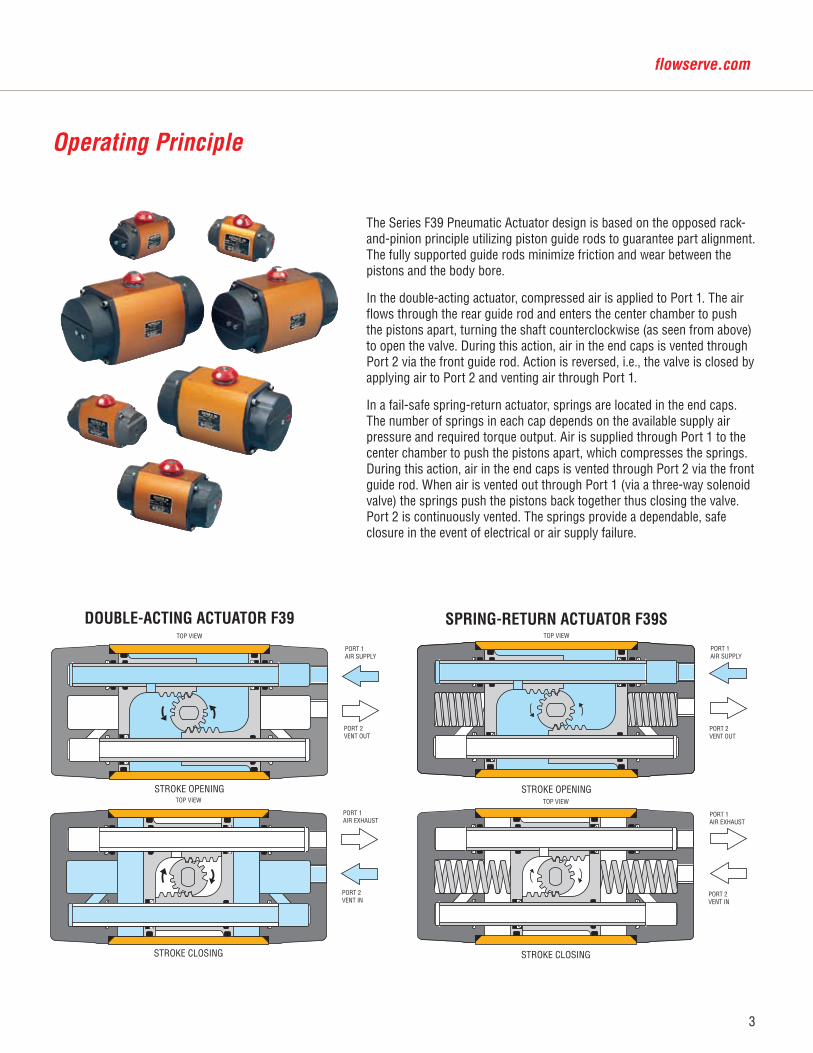
The Series F39 Pneumatic Actuator design is based on the opposed rack-and-pinion principle utilizing piston guide rods to guarantee part alignment. The fully supported guide rods minimize friction and wear between the pistons and the body bore.
In the double-acting actuator, compressed air is applied to Port 1. The air flows through the rear guide rod and enters the center chamber to push the pistons apart, turning the shaft counterclockwise (as seen from above) to open the valve. During this action, air in the end caps is vented through Port 2 via the front guide rod. Action is reversed, i.e., the valve is closed by applying air to Port 2 and venting air through Port 1.
In a fail-safe spring-return actuator, springs are located in the end caps. The number of springs in each cap depends on the available supply air pressure and required torque output. Air is supplied through Port 1 to the center chamber to push the pistons apart, which compresses the springs. During this action, air in the end caps is vented through Port 2 via the front guide rod. When air is vented out through Port 1 (via a three-way solenoid valve) the springs push the pistons back together thus closing the valve. Port 2 is continuously vented. The springs provide a dependable, safe closure in the event of electrical or air supply failure.
STROKE OPENING
TOP VIEW
SPRING-RETURN ACTUATOR F39S
PORT 1AIR SUPPLY
PORT 2VENT OUT
STROKE CLOSING
TOP VIEW
PORT 1AIR EXHAUST
PORT 2VENT IN
STROKE OPENING
TOP VIEW
PORT 1AIR SUPPLY
PORT 2VENT OUT
DOUBLE-ACTING ACTUATOR F39
STROKE CLOSING
TOP VIEW
PORT 1AIR EXHAUST
PORT 2VENT IN
Operating Principle
4
Product Specifications• Pneumatic Actuators are of a dual-piston
design for compactness, highest torque output, minimal air consumption and even weight distribution (balanced) on the valve stem.
• Actuators are equipped with two piston guide rods to bear the lateral rack-and-pinion thrust forces, increasing piston seal life and eliminating the possibility of cylinder scratching by the pistons. Elastomeric seals are not loaded as bearings.
• The torque is generated through a double rack-and-pinion gearing mechanism with full-length, uninterrupted engagement of the rack-and-pinion teeth.
• The rack is machined as part of the piston in order to extend the actuator life and eliminate hysteresis.
• Actuator housings are protected both internally and externally from corrosion using an anodizing process.
• Single-acting actuators use multi-springs at each end to eliminate uneven forces on the pistons and are field adaptable to balance reduced pressure air supplies.
• Actuators are supplied with end mounted limit stops for accurate position control
• Actuators can have optional integral end-mounted limit switches, reducing overall height and allowing the use of the actuator pinion for manual override (cannot be combined with limit stops).
• Actuators can be supplied with integral solenoid valving without the use of transfer tubes. Valving incorporates fail-safe action upon interruption of electrical signal.
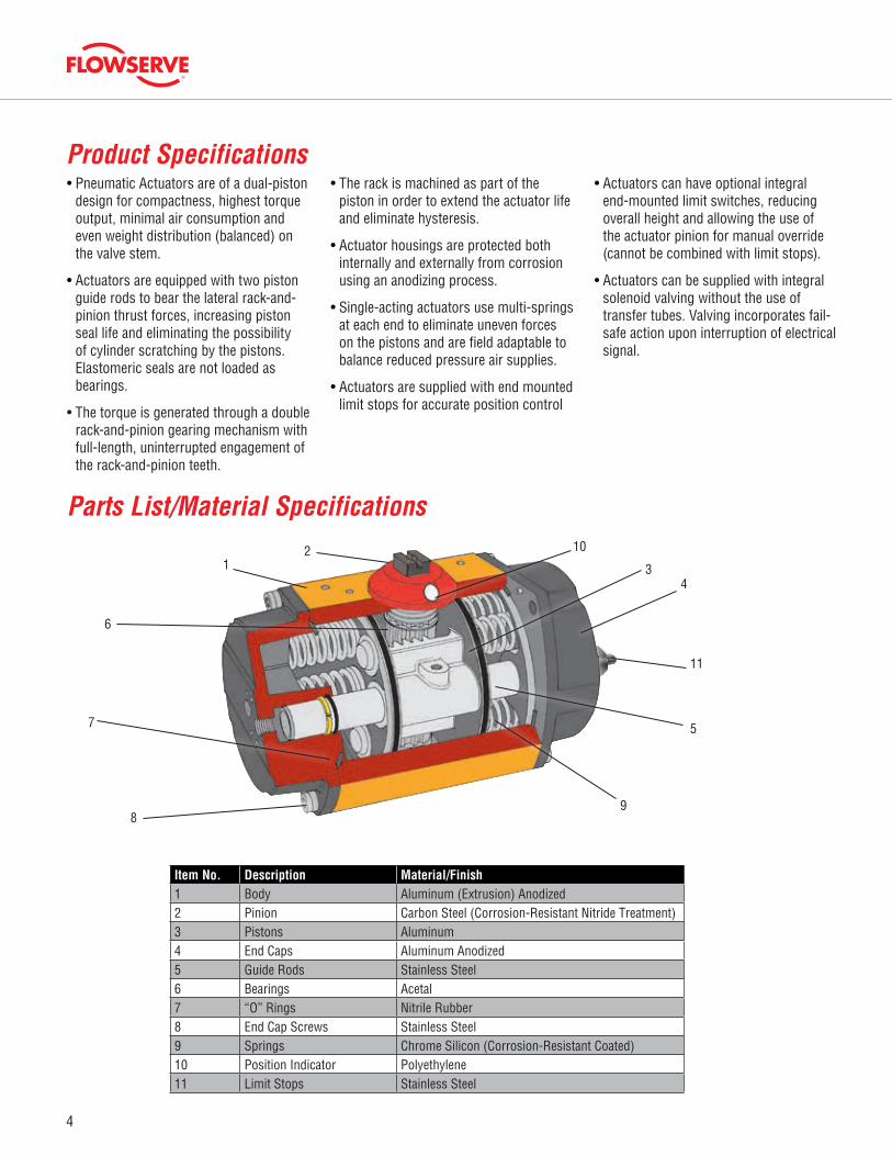
Parts List/Material Specifications
Item No. Description Material/Finish1 Body Aluminum (Extrusion) Anodized2 Pinion Carbon Steel (Corrosion-Resistant Nitride Treatment)3 Pistons Aluminum4 End Caps Aluminum Anodized5 Guide Rods Stainless Steel6 Bearings Acetal7 “O” Rings Nitrile Rubber8 End Cap Screws Stainless Steel9 Springs Chrome Silicon (Corrosion-Resistant Coated)10 Position Indicator Polyethylene11 Limit Stops Stainless Steel
8
7
6
9
5
43
1021
11
5
flowserve.com
End Mounted Solenoid BlockThe solenoid end cap of each actuator is pre-drilled to VDE/VDI NAMUR 3845 to allow rapid attachment of either a double-acting or spring-return solenoid control block.
The double-acting solenoid control block provides extremely fine and independent adjustments for speed control on the opening and closing strokes of a double-acting actuator (20:1 ratio). The double-acting solenoid control block can be overridden by manual operation of the control block spool.
The spring-return solenoid control block provides an optional adjustment for speed control on the spring stroke of a spring-return actuator. The advanced design prohibits environmental ingress to spring chamber during piston stroke extending actuator life.
Both double-acting and spring-return styles return to the actuator “closed” position (pistons together) upon electrical failure.
An extensive range of Weatherproof and Explosionproof coil options is available, along with a wide voltage selection including low-power and intrinsically safe.
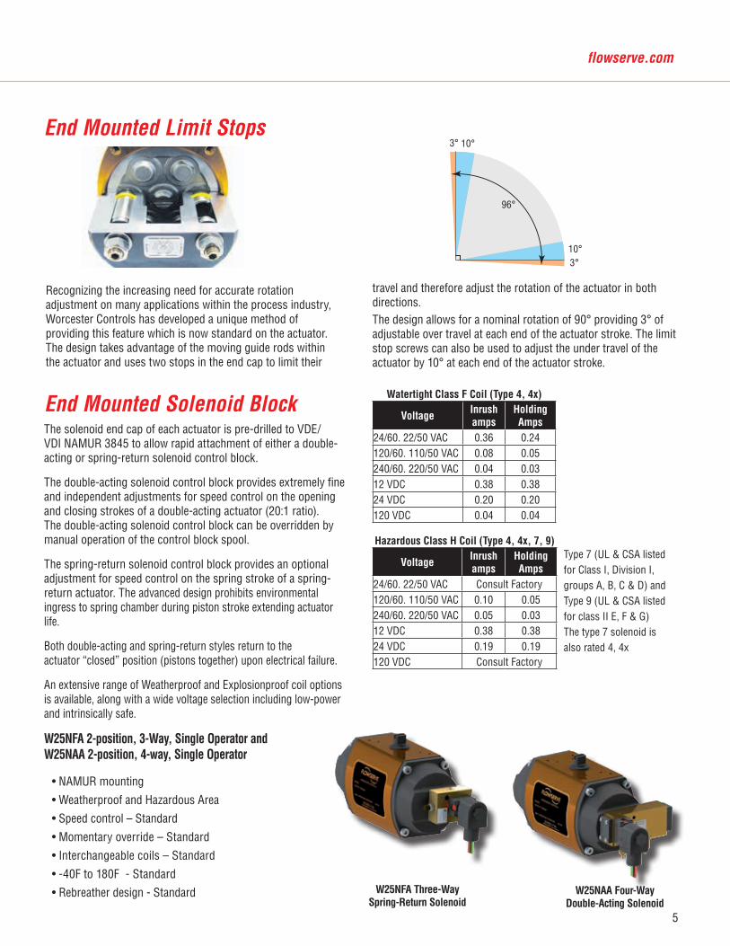
End Mounted Limit Stops
96°
3°
3°
10°
10°
Recognizing the increasing need for accurate rotation adjustment on many applications within the process industry, Worcester Controls has developed a unique method of providing this feature which is now standard on the actuator. The design takes advantage of the moving guide rods within the actuator and uses two stops in the end cap to limit their
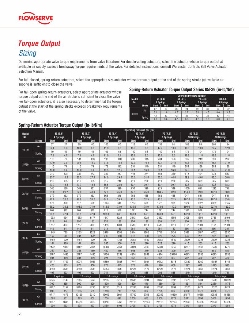
W25NFA Three-Way Spring-Return Solenoid
W25NAA Four-WayDouble-Acting Solenoid
Watertight Class F Coil (Type 4, 4x)
VoltageInrush amps
HoldingAmps
24/60. 22/50 VAC 0.36 0.24120/60. 110/50 VAC 0.08 0.05240/60. 220/50 VAC 0.04 0.0312 VDC 0.38 0.3824 VDC 0.20 0.20120 VDC 0.04 0.04
Hazardous Class H Coil (Type 4, 4x, 7, 9)
VoltageInrushamps
HoldingAmps
24/60. 22/50 VAC Consult Factory120/60. 110/50 VAC 0.10 0.05240/60. 220/50 VAC 0.05 0.0312 VDC 0.38 0.3824 VDC 0.19 0.19120 VDC Consult Factory
Type 7 (UL & CSA listed for Class I, Division I, groups A, B, C & D) and Type 9 (UL & CSA listed for class II E, F & G) The type 7 solenoid is also rated 4, 4x
travel and therefore adjust the rotation of the actuator in both directions.The design allows for a nominal rotation of 90° providing 3° of adjustable over travel at each end of the actuator stroke. The limit stop screws can also be used to adjust the under travel of the actuator by 10° at each end of the actuator stroke.
W25NFA 2-position, 3-Way, Single Operator and W25NAA 2-position, 4-way, Single Operator
• NAMUR mounting
• Weatherproof and Hazardous Area
• Speed control – Standard
• Momentary override – Standard
• Interchangeable coils – Standard
• -40F to 180F - Standard
• Rebreather design - Standard
6
Torque OutputSizingDetermine appropriate valve torque requirements from valve literature. For double-acting actuators, select the actuator whose torque output at available air supply exceeds breakaway torque requirements of the valve. For detailed instructions, consult Worcester Controls Ball Valve Actuator Selection Manual.
For fail-closed, spring-return actuators, select the appropriate size actuator whose torque output at the end of the spring stroke (at available air supply) is sufficient to close the valve.
For fail-open spring-return actuators, select appropriate actuator whose torque output at the end of the air stroke is sufficient to close the valve For fail-open actuators, it is also necessary to determine that the torque output at the start of the spring stroke exceeds breakaway requirements of the valve.
Spring-Return Actuator Torque Output (in-lb/Nm)
ModelNo.
Operating Pressure psi (Bar)50 (3.4) 60 (4.1) 70 (4.8) 80 (5.5)
2 Springs 2 Springs 2 Springs 4 SpringsStroke Start End Start End Start End Start End
05F39Air
27 16 35 24 49 38 53 373.1 1.8 4.0 2.7 5.5 4.3 6.0 4.2
Spring42 32 42 32 42 32 53 414.7 3.6 4.7 3.6 4.7 3.6 6.0 4.6
Spring-Return Actuator Torque Output Series 05F39 (in-lb/Nm)
ModelNo.
Operating Pressure psi (Bar)30 (2.0) 40 (2.7) 50 (3.4) 60 (4.1) 70 (4.8) 80 (5.5) 90 (6.2)
4 Springs 4 Springs 6 Springs 8 Springs 8 Springs 10 Springs 10 SpringsStroke Start End Start End Start End Start End Start End Start End Start End
10F39Air
57 27 89 60 105 60 118 60 152 91 168 89 201 1146.4 3.0 10.0 6.8 11.9 6.8 13.3 6.8 17.2 10.3 19.0 10.0 22.7 12.9
Spring70 42 70 42 105 63 140 84 140 84 175 104 175 1047.9 4.7 7.9 4.7 11.9 7.1 15.8 9.5 15.8 9.5 19.8 11.8 19.8 11.8
15F39Air
115 70 181 133 193 140 239 145 284 193 335 219 399 28213.0 7.9 20.5 15.0 21.8 15.8 27.0 16.4 32.1 21.8 37.8 24.8 45.1 31.9
Spring115 74 115 74 173 112 231 149 231 149 289 186 289 18613.0 8.4 13.0 8.4 19.5 12.6 26.1 16.8 26.1 16.8 32.6 21.0 32.6 21.0
20F39Air
210 128 332 243 389 257 443 274 558 389 612 404 735 51323.7 14.5 37.5 27.5 44.0 29.0 50.0 31.0 63.0 44.0 69.2 45.6 83.0 58.0
Spring210 135 210 135 315 212 419 272 419 272 525 339 525 33923.7 15.3 23.7 15.3 35.6 23.9 47.4 30.7 47.4 30.7 59.3 38.3 59.3 38.3
25F39Air
345 188 549 381 637 398 730 398 925 549 1009 611 1212 79739.0 21.2 62.0 43.0 72.0 45.0 82.5 45.0 104.5 62.0 114.0 69.0 137.0 90.0
Spring379 232 379 232 568 348 758 465 758 465 947 581 947 58142.8 26.2 42.8 26.2 64.2 39.3 85.6 52.5 85.6 52.5 107.0 65.6 107.0 65.6
30F39Air
577 320 912 628 1044 646 1204 690 1531 991 1682 1027 2009 134565.2 36.2 103.0 71.0 118.0 73.0 136.0 78.0 173.0 112.0 190.0 116.0 227.0 152.0
Spring609 372 609 372 912 558 1221 744 1221 744 1522 929 1522 92968.8 42.0 68.8 42.0 103.0 63.1 138.0 84.1 138.0 84.1 172.0 105.0 172.0 105.0
33F39Air
1053 564 1682 1177 1947 1221 2213 1221 2832 1859 3098 1850 3735 2460119 64 190 133 220 138 250 138 320 210 350 209 422 278
Spring1257 804 1257 804 1885 1204 2513 1611 2513 1611 3151 2009 3151 2009142 91 142 91 213 136 284 182 284 182 356 227 356 227
35F39Air
1345 780 2133 1522 2478 1593 2814 1682 3717 2434 3938 2487 4752 3230152 88 241 172 280 180 318 190 420 275 445 281 537 365
Spring1451 929 1451 929 2177 1398 2903 1859 2903 1859 3629 2328 3629 2328164 105 164 105 246 158 328 210 328 210 410 263 410 263
40F39Air
2142 1080 3407 2301 3983 2354 4469 2390 5620 3452 6257 3567 7523 4779242 122 385 260 450 266 505 270 635 390 707 403 850 540
Spring2487 1496 2487 1496 3726 2239 4974 2982 4974 29798 6213 3735 6213 3735281 169 281 169 421 253 562 337 562 337 702 422 702 422
42F39Air
3717 1797 5974 3983 6859 3938 7744 3894 9912 6018 10859 6000 13054 8142420 203 675 450 775 445 875 440 1120 680 1227 678 1475 920
Spring4390 2593 4390 2593 6584 3885 8779 5177 8779 5177 10974 6469 10974 6469496 293 496 293 744 439 992 585 992 585 1240 731 1240 731
8 springs 12 springs 16 springs 20 springs 20 springs 24 springs 24 springs
45F39Air
6275 3142 7965 3452 9735 3717 11505 3894 14868 6992 16470 7204 19736 10399709 355 900 390 1100 420 1300 440 1680 790 1861 814 2230 1175
Spring6107 3159 9160 4735 12213 6319 15266 7894 15266 7894 18320 9478 18320 9478690 357 1035 535 1380 714 1725 892 1725 892 2070 1071 2070 1071
50F39Air
9717 4876 12169 5310 15045 5664 17700 5753 20355 10399 24877 10585 30533 154881098 551 1375 600 1700 640 2000 650 2300 1175 2811 1196 3450 1750
Spring9647 4885 14470 7319 19293 9762 24116 12204 24116 12204 28940 14638 28940 146381090 552 1635 827 2180 1103 2725 1379 2725 1379 3270 1654 3270 1654
7
flowserve.com
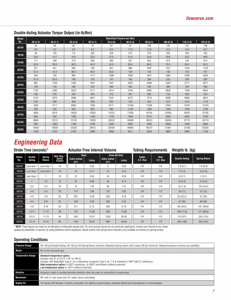
Double-Acting Actuator Torque Output (in-lb/Nm)
* NOTE: These figures are meant as an indication of obtainable speeds only. For more precise figures for any particular application, contact your Flowserve rep. Faster speeds are obtainable, if required, by using additional control equipment. Speed control with spring-return actuators only available on exhaust air (spring stroke).
Model No.
DoubleActing
SpringReturn
With Max.*Speed Control
Open Close DA OnlyUnder
4 ft. RunOver
4 ft. RunDouble Acting Spring ReturnCubic Inches
(in3)Litres
Cubic Inches (in3)
Litres
05F39 Less than 1 Less than 1 10 3 0.05 3 0.05 1/8" 1/4" 1.6 (0.7) 1.8 (0.8)
10F39 Less than 1 Less than 1 10 10 0.17 13 0.22 1/8" 1/4" 3 (1.3) 3.5(1.6)
15F39 Less than 1 1 15 21 0.35 24 0.39 1/8" 1/4" 6 (2.7) 7 (3.1)
20F39 1 1-2 15 42 0.69 45 0.74 1/8" 1/4" 10 (4.5) 12 (5.5)
25F39 2-3 2-3 18 74 1.22 80 1.31 1/8" 1/4" 16 (7.4) 18.5 (8.4)
30F39 3-4 3-4 20 114 1.86 125 2.05 1/4" 1/2" 24 (11) 27 (12)
33F39 4-5 7-8 25 207 3.39 292 4.79 1/4" 1/2" 50 (22.5) 57 (26)
35F39 4-5 8-9 25 240 3.93 338 5.54 1/4" 1/2" 57 (26) 66 (30)
40F39 5-6 9-10 30 411 6.73 500 8.19 1/4" 1/2" 96 (43.6) 107 (48.6)
42F39 10-11 11-12 36 732 12.00 848 13.89 1/4" 1/2" 158 (71.8) 177 (80.6)
45F39 10-12 11-13 40 824 13.51 1220 20.00 1/4" 1/2" 213 (97) 253 (115)
50F39 12-14 13-15 60 1457 23.87 1861 30.50 1/4" 1/2" 304 (138) 354 (161)
Operating ConditionsPressure Range 30–120 psi Double-Acting, 40–120 psi All Spring-Return Versions ( Standard spring-return units require 80 psi minimum. Reduced-pressure versions are available).
Media Air or non-corrosive gas.
Temperature Range Standard temperature option:Actuator only 0° to 212°F (-18° to 100°C)Actuator with Watertight Type 4, 4x or Hazardous Locations Type 4, 4x, 7 & 9 solenoid to 180°F (82°C) continuousHigh temperature option to 250°F continuous, to 300°F intermittent (without solenoid)Low temperature option to -40°F (without Solenoid)
Rotation Actuators rotate in counterclockwise direction when the outer air connection is pressurized.
Movement 90° with 3° over travel and 10° under travel controllable
Supply Air The Series F39 Actuator is factory lubricated. For optimum performance, standard filtered and lubricated air is recommended.
Model No.
Operating Pressure psi (Bar)30 (2.0) 40 (2.7) 50 (3.4) 60 (4.1) 70 (4.8) 80 (5.5) 90 (6.2) 100 (6.9) 110 (7.6) 120 (8.3)
05F3934 49 60 73 87 97 106 126 137 1483.8 5.5 6.8 8.3 9.8 11.0 12.0 14.2 15.5 16.7
10F3989 130 173 202 239 274 310 350 385 425
10.0 14.7 19.5 22.8 27.0 31.0 35.0 39.6 43.5 48.0
15F39177 248 319 389 460 531 602 673 743 81420.0 28.0 36.0 44.0 52.0 60.0 68.0 76.0 84.0 92.0
20F39327 451 584 708 841 965 1097 1221 1354 147837.0 51.0 66.0 80.0 95.0 109 124 138 153 167
25F39540 752 965 1177 1389 1620 1841 2062 2283 250561.0 85.0 109 133 157 183 208 233 258 283
30F39885 1239 1593 1947 2301 2655 3009 3363 3717 4071100 140 180 220 260 300 340 380 420 460
33F391735 2390 3053 3717 4514 5195 5885 6638 7346 8054196 270 345 420 510 587 665 750 830 910
35F392124 2974 3806 4691 5531 6372 7213 8098 8983 9824240 336 430 530 625 720 815 915 1015 1110
40F393390 4717 6062 7390 8717 10169 11505 12921 14337 15753383 533 685 835 985 1149 1300 1460 1620 1780
42F395885 8319 10620 12833 15222 17638 20134 22568 25001 27435665 940 1200 1450 1720 1993 2275 2550 2825 3100
45F398806 12213 15753 19293 22833 26408 29913 33630 37170 40710995 1380 1780 2180 2580 2984 3380 3800 4200 4600
50F3913620 19028 24338 29913 35400 40860 46374 51861 57348 628351539 2150 2750 3380 4000 4617 5240 5860 6480 7100
Stroke Time (seconds)* Actuator Free Internal Volume Tubing Requirements Weights lb. (kg)
Engineering Data
8
U HOLES4 POSITIONS
M5 x 6.0 DEEP4 POSITIONS
M6 x 14.0 DEEPFrom TOP FACE
EN 15714-3 NAMUR TOP ACCESSORY MOUNTING
NAMUR SLOT
14.0
M6
REF
.
NAM
UR
SLO
T
STAR
DR
IVE
EN IS
O 5
211
MIN
.
VENT PLUG(SPRING RETURNACTUATORS)THIS HOLE ONLY
1/4 NPT PORTS
EN 15714-3 NAMURINLET ENDCAP
U HOLES4 POSITIONS
I REF
.
J A/
F
STAR D
RIVE
EN IS
O 5211
I REF.EN ISO 5211 F PATTERNG PCD H HOLES
ACTUATOR MOUNTINGATTACHMENT EN ISO 5211
LIMIT STOP ENDCAP
R A/FNUT
Q A/
FHE
X. K
EY
80.0
S
30.0
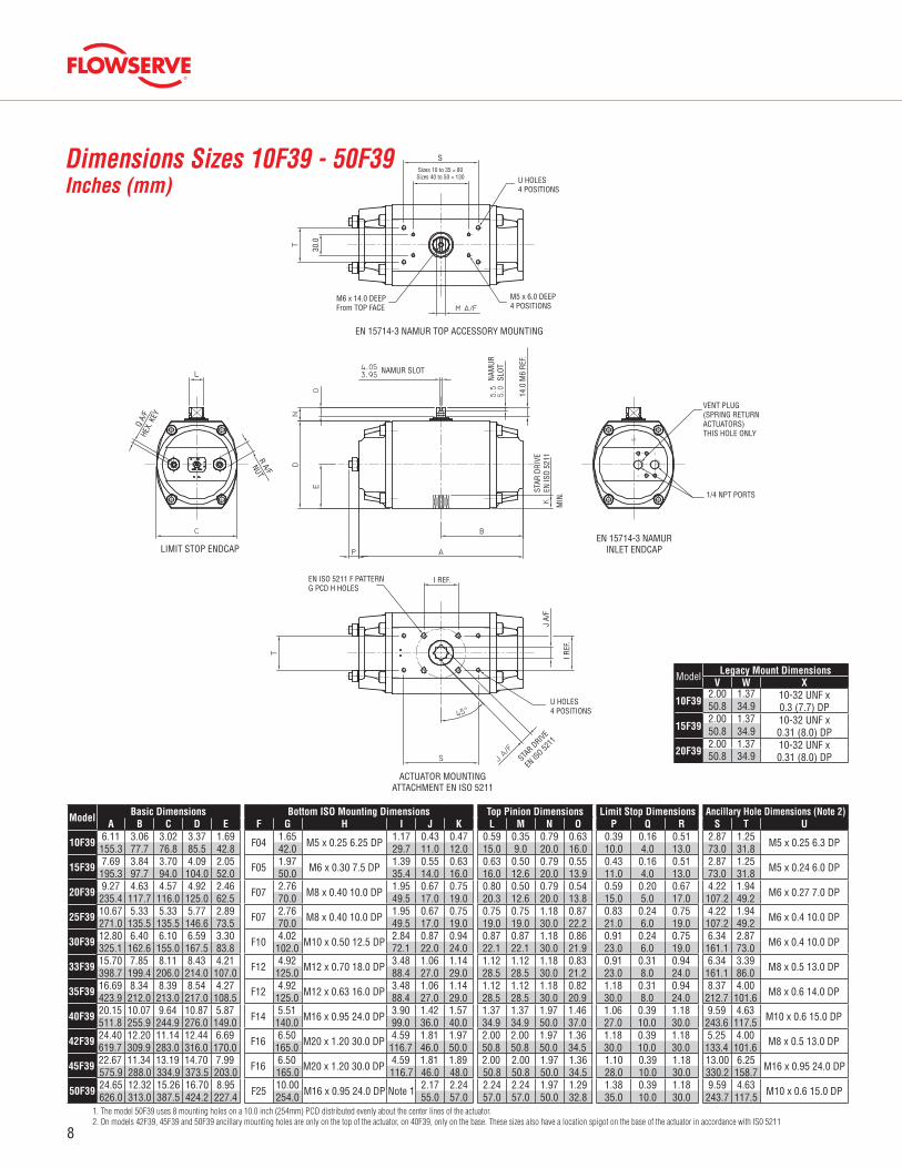
Dimensions Sizes 10F39 - 50F39Inches (mm)
Model Legacy Mount DimensionsV W X
10F392.00 1.37 10-32 UNF x
0.3 (7.7) DP50.8 34.9
15F392.00 1.37 10-32 UNF x
0.31 (8.0) DP50.8 34.9
20F392.00 1.37 10-32 UNF x
0.31 (8.0) DP50.8 34.9
ModelBasic Dimensions Bottom ISO Mounting Dimensions Top Pinion Dimensions Limit Stop Dimensions Ancillary Hole Dimensions (Note 2)
A B C D E F G H I J K L M N O P Q R S T U
10F39 6.11 3.06 3.02 3.37 1.69 F04 1.65 M5 x 0.25 6.25 DP 1.17 0.43 0.47 0.59 0.35 0.79 0.63 0.39 0.16 0.51 2.87 1.25 M5 x 0.25 6.3 DP155.3 77.7 76.8 85.5 42.8 42.0 29.7 11.0 12.0 15.0 9.0 20.0 16.0 10.0 4.0 13.0 73.0 31.8
15F39 7.69 3.84 3.70 4.09 2.05 F05 1.97 M6 x 0.30 7.5 DP 1.39 0.55 0.63 0.63 0.50 0.79 0.55 0.43 0.16 0.51 2.87 1.25 M5 x 0.24 6.0 DP195.3 97.7 94.0 104.0 52.0 50.0 35.4 14.0 16.0 16.0 12.6 20.0 13.9 11.0 4.0 13.0 73.0 31.8
20F39 9.27 4.63 4.57 4.92 2.46 F07 2.76 M8 x 0.40 10.0 DP 1.95 0.67 0.75 0.80 0.50 0.79 0.54 0.59 0.20 0.67 4.22 1.94 M6 x 0.27 7.0 DP235.4 117.7 116.0 125.0 62.5 70.0 49.5 17.0 19.0 20.3 12.6 20.0 13.8 15.0 5.0 17.0 107.2 49.2
25F39 10.67 5.33 5.33 5.77 2.89 F07 2.76 M8 x 0.40 10.0 DP 1.95 0.67 0.75 0.75 0.75 1.18 0.87 0.83 0.24 0.75 4.22 1.94 M6 x 0.4 10.0 DP271.0 135.5 135.5 146.6 73.5 70.0 49.5 17.0 19.0 19.0 19.0 30.0 22.2 21.0 6.0 19.0 107.2 49.2
30F39 12.80 6.40 6.10 6.59 3.30 F10 4.02 M10 x 0.50 12.5 DP 2.84 0.87 0.94 0.87 0.87 1.18 0.86 0.91 0.24 0.75 6.34 2.87 M6 x 0.4 10.0 DP325.1 162.6 155.0 167.5 83.8 102.0 72.1 22.0 24.0 22.1 22.1 30.0 21.9 23.0 6.0 19.0 161.1 73.0
33F39 15.70 7.85 8.11 8.43 4.21 F12 4.92 M12 x 0.70 18.0 DP 3.48 1.06 1.14 1.12 1.12 1.18 0.83 0.91 0.31 0.94 6.34 3.39 M8 x 0.5 13.0 DP398.7 199.4 206.0 214.0 107.0 125.0 88.4 27.0 29.0 28.5 28.5 30.0 21.2 23.0 8.0 24.0 161.1 86.0
35F39 16.69 8.34 8.39 8.54 4.27 F12 4.92 M12 x 0.63 16.0 DP 3.48 1.06 1.14 1.12 1.12 1.18 0.82 1.18 0.31 0.94 8.37 4.00 M8 x 0.6 14.0 DP423.9 212.0 213.0 217.0 108.5 125.0 88.4 27.0 29.0 28.5 28.5 30.0 20.9 30.0 8.0 24.0 212.7 101.6
40F39 20.15 10.07 9.64 10.87 5.87 F14 5.51 M16 x 0.95 24.0 DP 3.90 1.42 1.57 1.37 1.37 1.97 1.46 1.06 0.39 1.18 9.59 4.63 M10 x 0.6 15.0 DP511.8 255.9 244.9 276.0 149.0 140.0 99.0 36.0 40.0 34.9 34.9 50.0 37.0 27.0 10.0 30.0 243.6 117.5
42F39 24.40 12.20 11.14 12.44 6.69 F16 6.50 M20 x 1.20 30.0 DP 4.59 1.81 1.97 2.00 2.00 1.97 1.36 1.18 0.39 1.18 5.25 4.00 M8 x 0.5 13.0 DP619.7 309.9 283.0 316.0 170.0 165.0 116.7 46.0 50.0 50.8 50.8 50.0 34.5 30.0 10.0 30.0 133.4 101.6
45F39 22.67 11.34 13.19 14.70 7.99 F16 6.50 M20 x 1.20 30.0 DP 4.59 1.81 1.89 2.00 2.00 1.97 1.36 1.10 0.39 1.18 13.00 6.25 M16 x 0.95 24.0 DP575.9 288.0 334.9 373.5 203.0 165.0 116.7 46.0 48.0 50.8 50.8 50.0 34.5 28.0 10.0 30.0 330.2 158.7
50F39 24.65 12.32 15.26 16.70 8.95 F25 10.00 M16 x 0.95 24.0 DP Note 1 2.17 2.24 2.24 2.24 1.97 1.29 1.38 0.39 1.18 9.59 4.63 M10 x 0.6 15.0 DP626.0 313.0 387.5 424.2 227.4 254.0 55.0 57.0 57.0 57.0 50.0 32.8 35.0 10.0 30.0 243.7 117.51. The model 50F39 uses 8 mounting holes on a 10.0 inch (254mm) PCD distributed evenly about the center lines of the actuator. 2. On models 42F39, 45F39 and 50F39 ancillary mounting holes are only on the top of the actuator, on 40F39, only on the base. These sizes also have a location spigot on the base of the actuator in accordance with IS0 5211
Sizes 10 to 35 = 80Sizes 40 to 50 = 130
9
flowserve.com
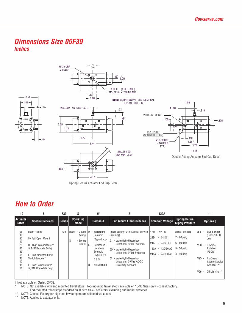
Dimensions Size 05F39 Inches
Double-Acting Actuator End Cap Detail
2.64
1.51
.47
.49
2.251.13
.70
.501.00
.501.00
.236/.232 - ACROSS FLATS
2.72
5.44
.476
.32
1.64
1.89
3.77
#8-32 UNF.28 DEEP
DIA
DIA
.358/.354 SQ..394 MIN. DEEP
4.16
8 HOLES (4 PER FACE)M5-.8P-6H x .236 DP. MIN.
NOTE: MOUNTING PATTERN IDENTICALTOP AND BOTTOM
1.500
2 HOLES 1/8˝ NPT
.169
.375
VENT PLUG(SPRING RETURN)
#10-32 UNFx .20 DEEP
TYP:
4.16
.0931.687
.319
.375
Spring Return Actuator End Cap Detail
10 E F39 S W Z 120A ----- ----
ActuatorSizes
Special Services SeriesOperating
ModeSolenoid End Mount Limit Switches Solenoid Voltage
Spring Return Supply Pressure Options †
051015202530333540424550
Blank - None
9 - Fail-Open Mount
H - High Temperature**(N & SN Models Only)
E - End mounted Limit Switch Module*
L - Low Temperature**(N, SN, W models only)
F39 Blank - Double Acting
S - Spring Return
W - Watertight Solenoid
(Type 4, 4x)
X - Hazardous Locations Solenoid (Type 4, 4x,
7 & 9)
N - No Solenoid
(must specify "E" in Special Service Column)†
Z - Watertight/Hazardous Locations, SPDT Switches
ZD - Watertight/Hazardous Locations, DPDT Switches
Z1 - Watertight/Hazardous Locations, 2-Wire AC/DC Proximity Sensors
12D - 12 DC
24D - 24 DC
24A - 24/60 AC
120A - 120/60 AC
240A - 240/60 AC
Blank - 80 psig
7 - 70 psig
6 - 60 psig
5 - 50 psig
4 - 40 psig
V54 - SST Springs (Sizes 10-30 only)
V90 - Reverse Rotation (FCCW)
V95 - NorGuard Severe Service Actuator***
V96 - CE Marking***
How to Order
† Not available on Series 05F39. * NOTE: Not available with end mounted travel stops. Top-mounted travel stops available on 10-30 Sizes only - consult factory. End-mounted travel stops standard on all size 10-42 actuators, excluding end mount switches. ** NOTE: Consult Factory for high and low temperature solenoid variations. *** NOTE: Applies to actuator only.
10
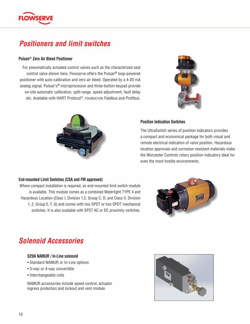
Pulsair® Zero Air Bleed Positioner
For pneumatically actuated control valves such as the characterized seat control valve shown here, Flowserve offers the Pulsair® loop-powered
positioner with auto-calibration and zero air bleed. Operated by a 4-20 mA analog signal, Pulsair’s® microprocessor and three-button keypad provide
on-site automatic calibration, split-range, speed adjustment, fault delay etc. Available with HART Protocol®, FOUNDATION Fieldbus and Profibus.
Position Indication Switches
The UltraSwitch series of position indicators provides a compact and economical package for both visual and remote electrical indication of valve position. Hazardous location approvals and corrosion resistant materials make the Worcester Controls rotary position indicators ideal for even the most hostile environments.
End-mounted Limit Switches (CSA and FM approved)Where compact installation is required, an end-mounted limit switch module
is available. This module comes as a combined Watertight TYPE 4 and Hazardous Location (Class I, Division 1,2, Group C, D; and Class II, Division
1, 2, Group E, F, G) and comes with two SPDT or two DPDT mechanical switches. It is also available with SPST AC or DC proximity switches.
Positioners and limit switches
S25N NAMUR / In-Line solenoid• Standard NAMUR or In-Line options
• 3-way or 4-way convertible
• Interchangeable coils
NAMUR accessories include speed control, actuator ingress protection and lockout and vent module
Solenoid Accessories
11
flowserve.com
Member of ASI Trade Organization and the Open DeviceNet Vendor Association
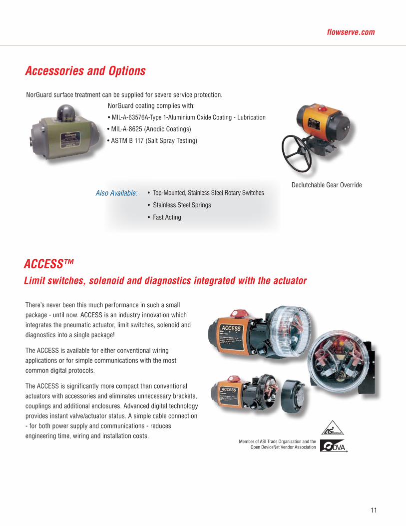
There’s never been this much performance in such a small package - until now. ACCESS is an industry innovation which integrates the pneumatic actuator, limit switches, solenoid and diagnostics into a single package!
The ACCESS is available for either conventional wiring applications or for simple communications with the most common digital protocols.
The ACCESS is significantly more compact than conventional actuators with accessories and eliminates unnecessary brackets, couplings and additional enclosures. Advanced digital technology provides instant valve/actuator status. A simple cable connection - for both power supply and communications - reduces engineering time, wiring and installation costs.
ACCESS™Limit switches, solenoid and diagnostics integrated with the actuator
Accessories and Options
• Top-Mounted, Stainless Steel Rotary Switches
• Stainless Steel Springs
• Fast Acting
Declutchable Gear Override
NorGuard surface treatment can be supplied for severe service protection.
NorGuard coating complies with:
• MIL-A-63576A-Type 1-Aluminium Oxide Coating - Lubrication
• MIL-A-8625 (Anodic Coatings)
• ASTM B 117 (Salt Spray Testing)
Also Available:
12
© 2015 Flowserve Corporation, Irving, Texas, USA. Flowserve and Worcester Controls are registered trademarks of Flowserve Corporation.
Flowserve Corporation has established industry leadership in the design and manufacture of its products. When properly selected, this Flowserve product is designed to perform its intended function safely during its useful life. However, the purchaser or user of Flowserve products should be aware that Flowserve products might be used in numerous applications under a wide variety of industrial service condi-tions. Although Flowserve can (and often does) provide general guidelines, it cannot provide specific data and warnings for all possible applications. The purchaser/user must therefore assume the ultimate responsibility for the proper sizing and selection, installation, operation, and maintenance of Flowserve products. The purchaser/user should read and understand the Installation Operation Maintenance (IOM) instructions included with the product, and train its employees and contractors in the safe use of Flowserve products in connection with the specific application.
While the information and specifications contained in this literature are believed to be accurate, they are supplied for informative purposes only and should not be considered certified or as a guarantee of satisfactory results by reliance thereon. Nothing contained herein is to be construed as a warranty or guarantee, express or implied, regarding any matter with respect to this product. Because Flowserve is continually improving and upgrading its product design, the specifications, dimensions and information contained herein are subject to change without notice. Should any question arise concerning these provisions, the purchaser/user should contact Flowserve Corporation at any one of its worldwide operations or offices.
FLOWSERVE Flow Control1978 Foreman DriveCookeville, Tennessee 38501USA
Phone: 931 432 4021Fax: 931 432 5518
FCD WCENBR1003-04-AQ 09/2016 Printed in USA.
For more information about Flowserve Corporation, visit www.flowserve.com or call USA 1-800-225-6989.
Contact: