Embed Size (px)
Citation preview
Work partially supported by VisionRT
Background of frameless intracranial stereotactic radiosurgery
UCSD SRS/SRT procedure
Clinical Results
Summary
Total prescribed doses : order of 10 ‐ 50 Gy
Planning targets are small : from 1 to 35 cm3.
Positional and numerical accuracy in dose delivery are ±1mm and ±5%, respectively.
Accurate determination of the target volume and its location with stereotactic techniques.
Conformal Dose distributions : sharp dose fall‐off outside the target volume.
Accurate knowledge of the total dose and fractionation scheme required for treatment of a particular disease.
Patient comfort
Ease of treatment
Similar or better accuracy of positioning
Potential for hypofractionatedtreatments
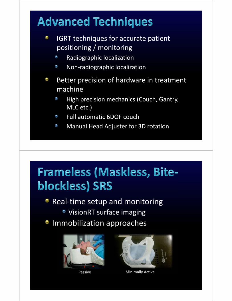
IGRT techniques for accurate patient positioning / monitoring
Radiographic localization
Non‐radiographic localization
Better precision of hardware in treatment machine
High precision mechanics (Couch, Gantry, MLC etc.)
Full automatic 6DOF couch
Manual Head Adjuster for 3D rotation
Real‐time setup and monitoringVisionRT surface imaging
Immobilization approaches
Passive Minimally Active
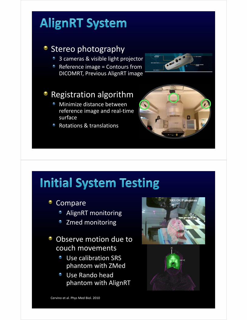
Stereo photography3 cameras & visible light projector
Reference image = Contours from DICOMRT, Previous AlignRT image
Registration algorithmMinimize distance between reference image and real‐time surface
Rotations & translations
Compare AlignRT monitoring
Zmed monitoring
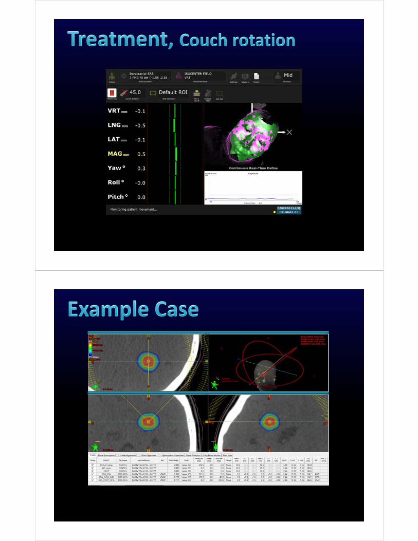
Observe motion due to couch movements
Use calibration SRS phantom with ZMed
Use Rando head phantom with AlignRT
Cervino et al. Phys Med Biol. 2010
Cervino et al. Phys Med Biol. 2010
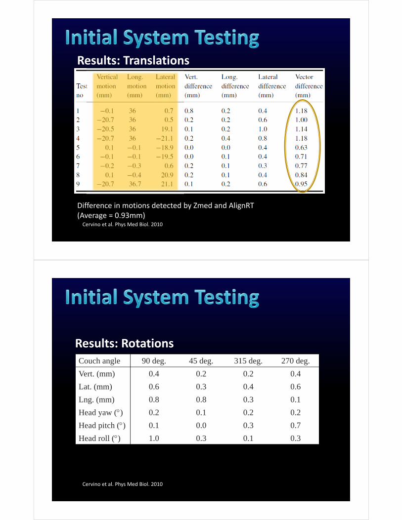
Difference in motions detected by Zmed and AlignRT(Average = 0.93mm)
Results: Translations
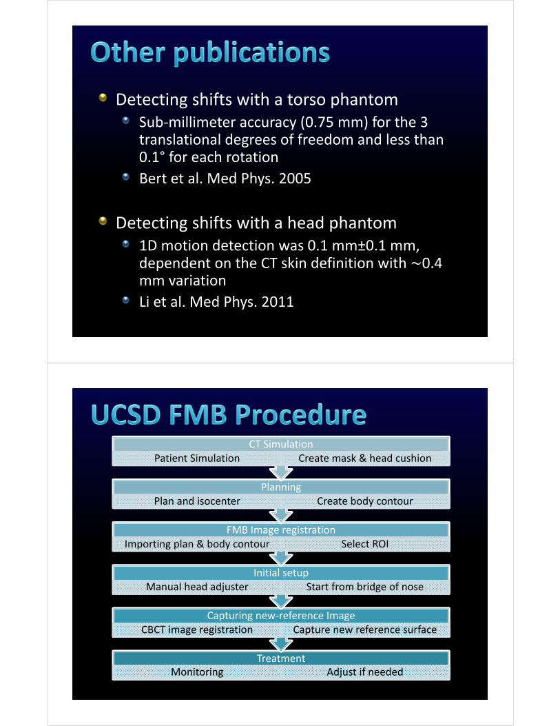
Cervino et al. Phys Med Biol. 2010
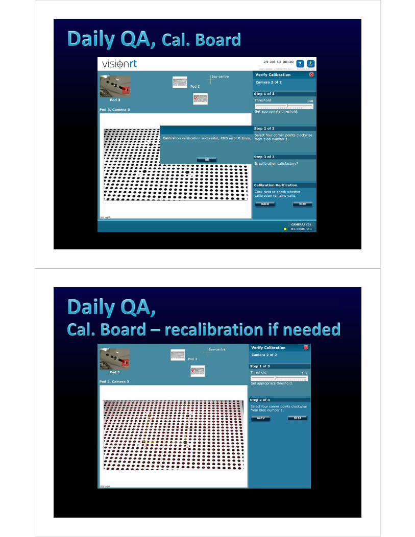
Results: RotationsCouch angle 90 deg. 45 deg. 315 deg. 270 deg.
Vert. (mm) 0.4 0.2 0.2 0.4
Lat. (mm) 0.6 0.3 0.4 0.6
Lng. (mm) 0.8 0.8 0.3 0.1
Head yaw () 0.2 0.1 0.2 0.2
Head pitch () 0.1 0.0 0.3 0.7
Head roll () 1.0 0.3 0.1 0.3
Detecting shifts with a torso phantomSub‐millimeter accuracy (0.75 mm) for the 3 translational degrees of freedom and less than 0.1° for each rotation
Bert et al. Med Phys. 2005
Detecting shifts with a head phantom1D motion detection was 0.1 mm±0.1 mm, dependent on the CT skin definition with 0.4 mm variation
Li et al. Med Phys. 2011
TreatmentMonitoring Adjust if needed
Capturing new‐reference ImageCBCT image registration Capture new reference surface
Initial setupManual head adjuster Start from bridge of nose
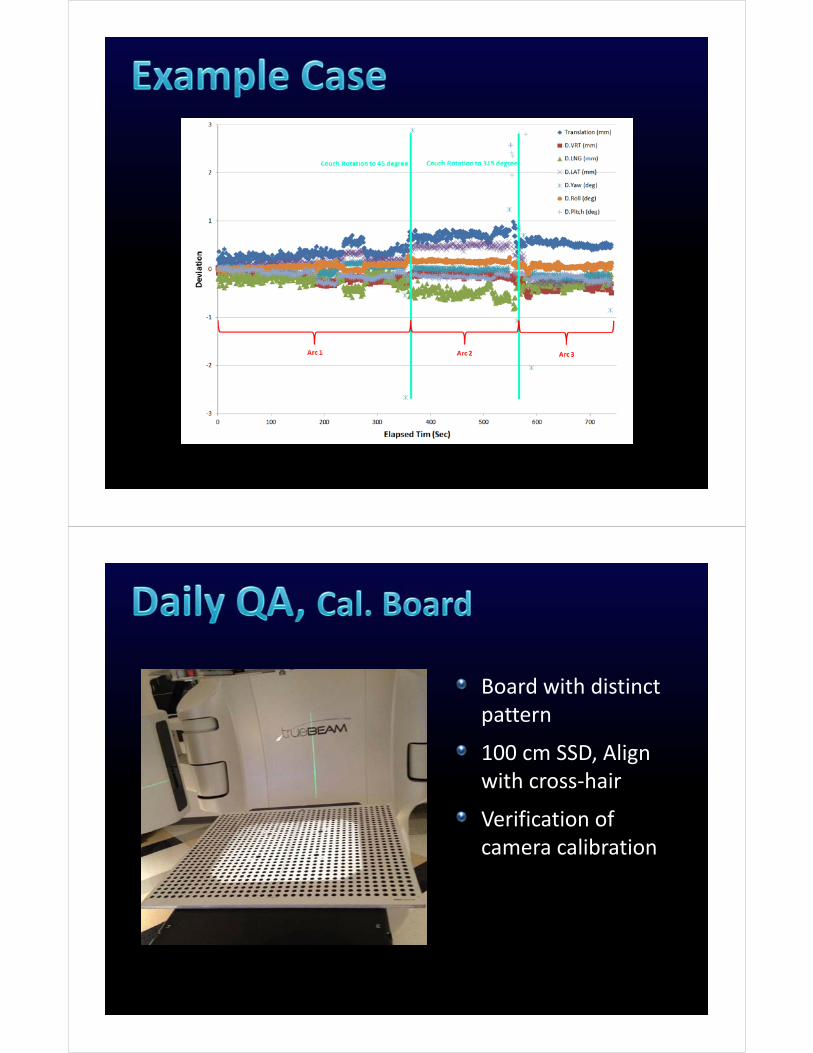
FMB Image registrationImporting plan & body contour Select ROI
PlanningPlan and isocenter Create body contour
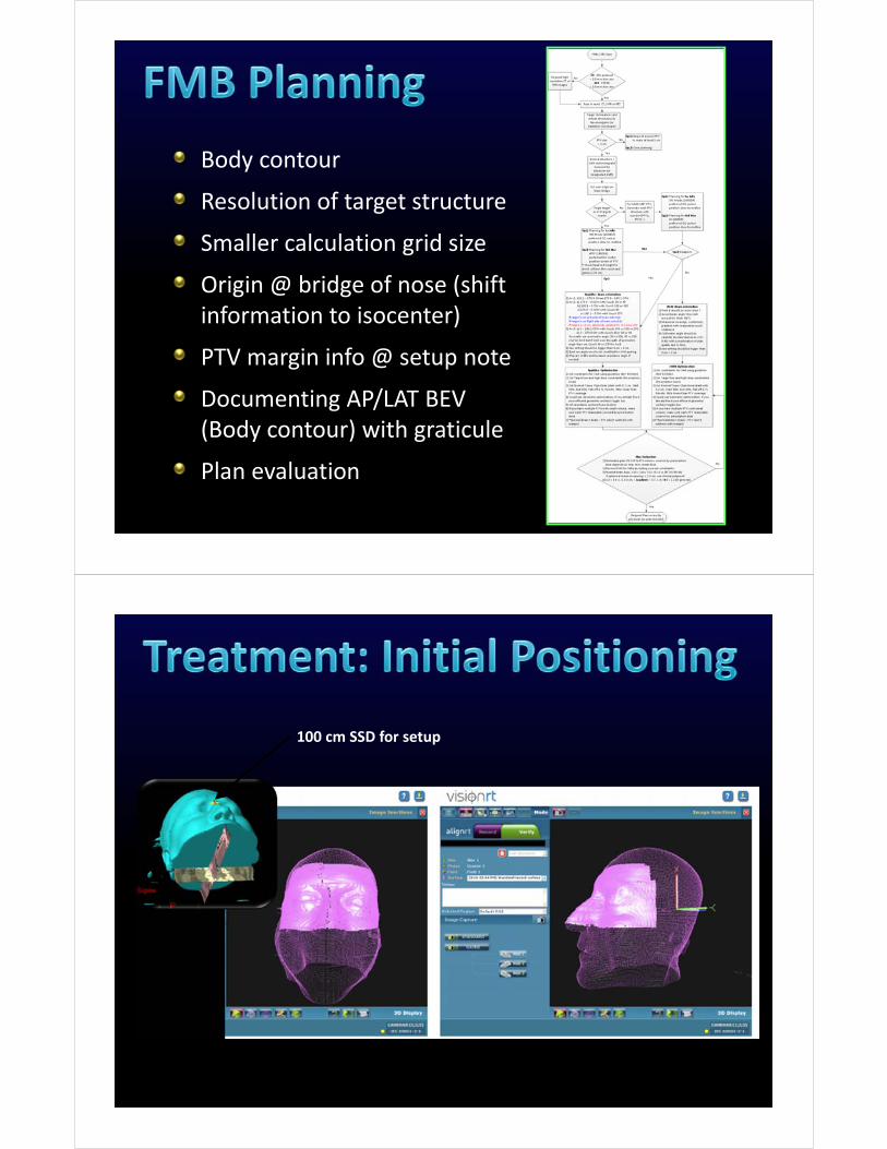
CT SimulationPatient Simulation Create mask & head cushion
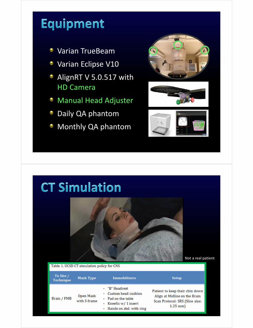
Varian TrueBeam
Varian Eclipse V10
AlignRT V 5.0.517 with HD Camera
Manual Head Adjuster
Daily QA phantom
Monthly QA phantom
Not a real patient
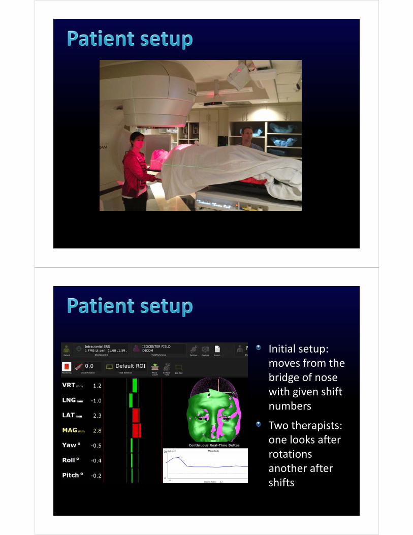
Body contour
Resolution of target structure
Smaller calculation grid size
Origin @ bridge of nose (shift information to isocenter)
PTV margin info @ setup note
Documenting AP/LAT BEV (Body contour) with graticule
Plan evaluation
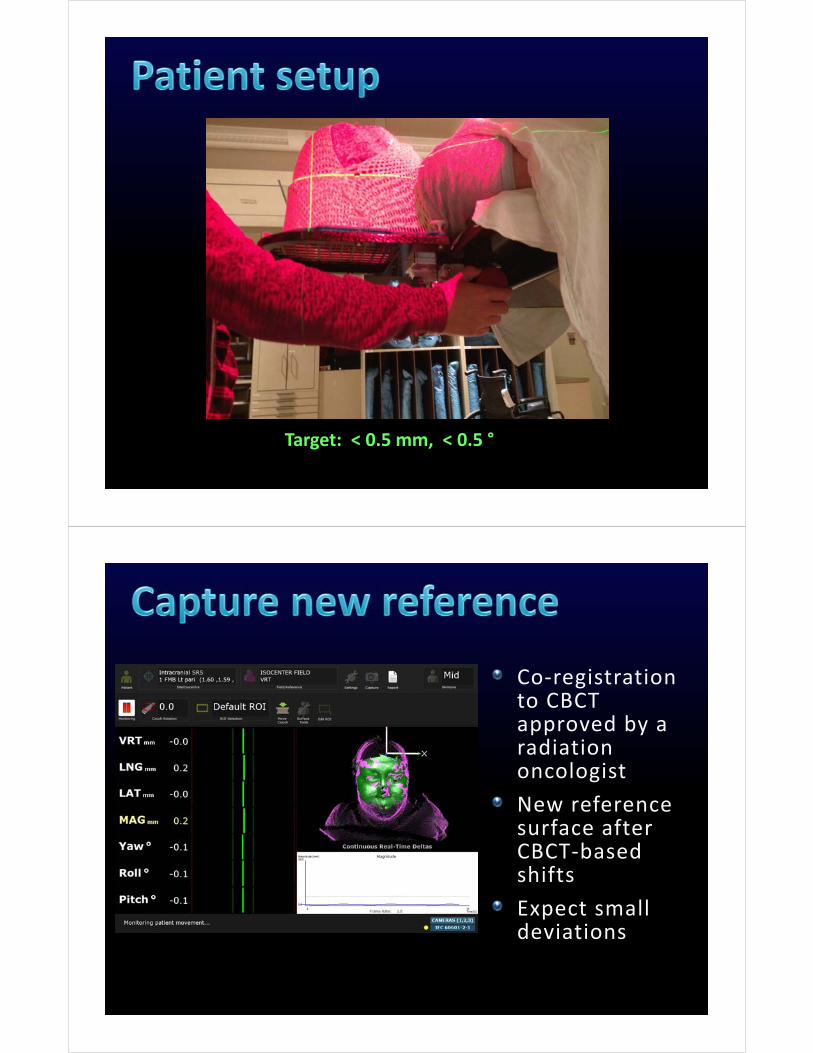
100 cm SSD for setup
Initial setup: moves from the bridge of nose with given shift numbers
Two therapists: one looks after rotations another after shifts
Target: < 0.5 mm, < 0.5 °
Co‐registration to CBCT approved by a radiation oncologist
New reference surface after CBCT‐based shifts
Expect small deviations
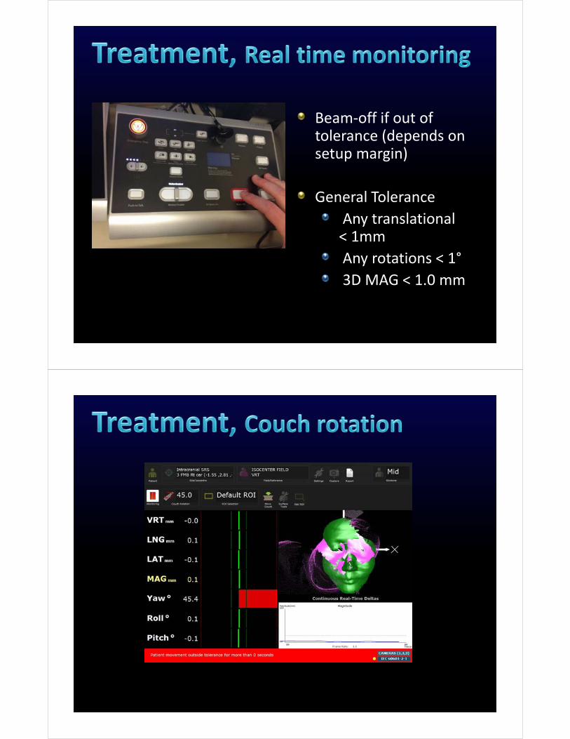
Beam‐off if out of tolerance (depends on setup margin)
General Tolerance
Any translational < 1mm
Any rotations < 1°
3D MAG < 1.0 mm
Board with distinct pattern
100 cm SSD, Align with cross‐hair
Verification of camera calibration
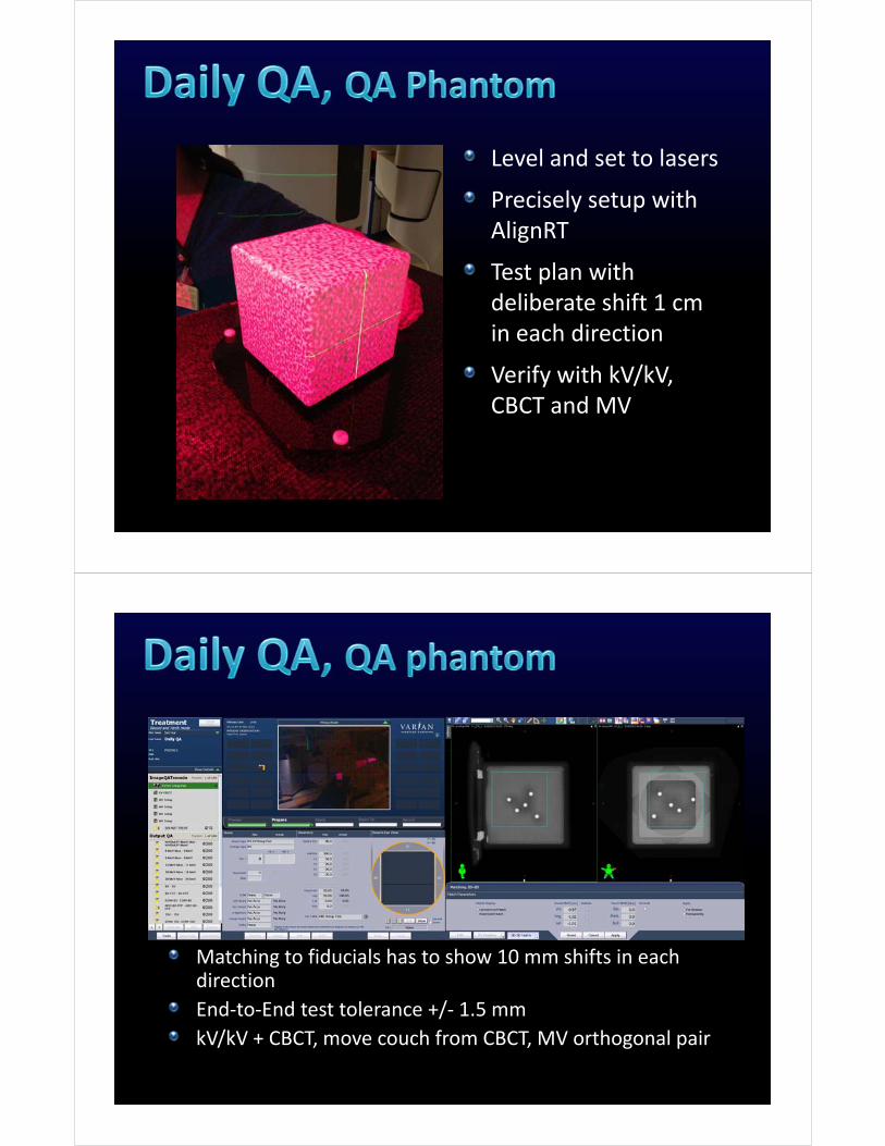
Level and set to lasers
Precisely setup with AlignRT
Test plan with deliberate shift 1 cm in each direction
Verify with kV/kV, CBCT and MV
Matching to fiducials has to show 10 mm shifts in each direction
End‐to‐End test tolerance +/‐ 1.5 mm
kV/kV + CBCT, move couch from CBCT, MV orthogonal pair
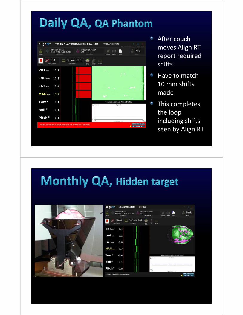
After couch moves Align RT report required shifts
Have to match 10 mm shifts made
This completes the loop including shifts seen by Align RT
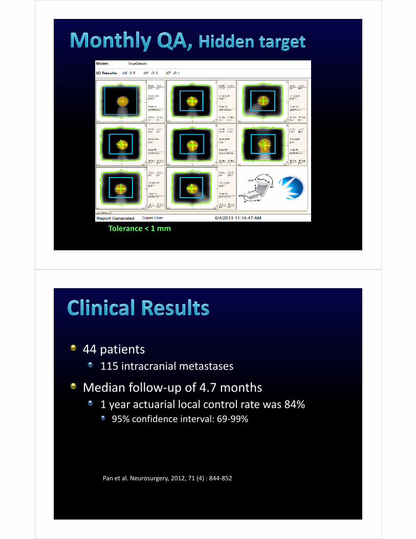
Tolerance < 1 mm
44 patients115 intracranial metastases
Median follow‐up of 4.7 months1 year actuarial local control rate was 84%
95% confidence interval: 69‐99%
Pan et al. Neurosurgery, 2012, 71 (4) : 844‐852
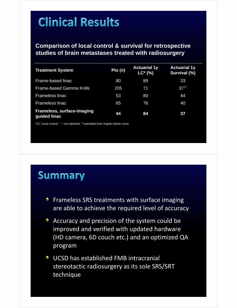
Comparison of local control & survival for retrospective studies of brain metastases treated with radiosurgery
Treatment System Pts (n)Actuarial 1y
LC* (%)Actuarial 1y Survival (%)
Frame-based linac 80 89 33
Frame-based Gamma Knife 205 71 37††
Frameless linac 53 80 44
Frameless linac 65 76 40
Frameless, surface-imaging guided linac
44 84 37
*LC: local control; † -: not reported; ††estimated from Kaplan-Meier curve
Frameless SRS treatments with surface imaging are able to achieve the required level of accuracy
Accuracy and precision of the system could be improved and verified with updated hardware (HD camera, 6D couch etc.) and an optimized QA program
UCSD has established FMB intracranial stereotactic radiosurgery as its sole SRS/SRT technique

Todd Pawlicki, Ph.D.
Steve Jiang, Ph.D.
Vitali Moiseenko, Ph.D.
Adam Paxton, Ph.D.
UCSD SRS TEAM
Kevin Murphy, M.D.
Parag Sanghvi, M.D.
Jona Hattangadi, M.D.
Clark Chen, M.D.
Grace Kim, Ph.D.
Jane Uhl, CMD