Embed Size (px)
Citation preview
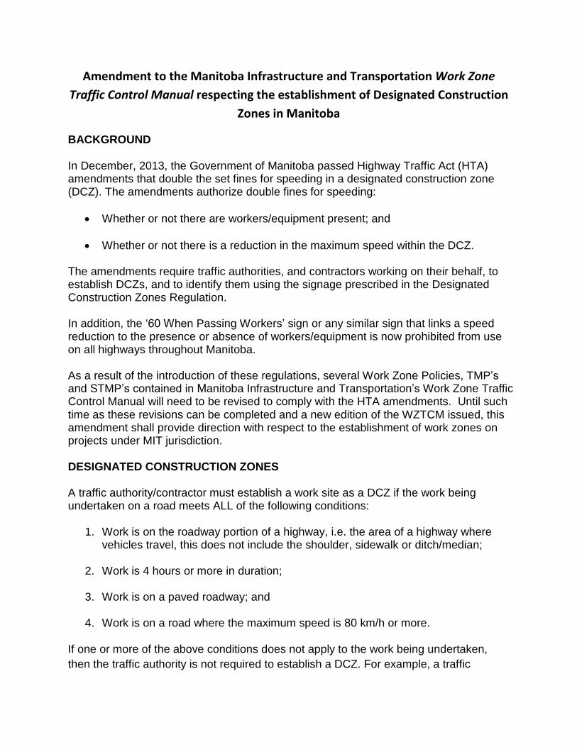
Amendment to the Manitoba Infrastructure and Transportation Work Zone
Traffic Control Manual respecting the establishment of Designated Construction
Zones in Manitoba
BACKGROUND
In December, 2013, the Government of Manitoba passed Highway Traffic Act (HTA) amendments that double the set fines for speeding in a designated construction zone (DCZ). The amendments authorize double fines for speeding:
Whether or not there are workers/equipment present; and
Whether or not there is a reduction in the maximum speed within the DCZ.
The amendments require traffic authorities, and contractors working on their behalf, to establish DCZs, and to identify them using the signage prescribed in the Designated Construction Zones Regulation. In addition, the �60 When Passing Workers� sign or any similar sign that links a speed reduction to the presence or absence of workers/equipment is now prohibited from use on all highways throughout Manitoba. As a result of the introduction of these regulations, several Work Zone Policies, TMP�s
and STMP�s contained in Manitoba Infrastructure and Transportation�s Work Zone Traffic Control Manual will need to be revised to comply with the HTA amendments. Until such time as these revisions can be completed and a new edition of the WZTCM issued, this amendment shall provide direction with respect to the establishment of work zones on projects under MIT jurisdiction. DESIGNATED CONSTRUCTION ZONES A traffic authority/contractor must establish a work site as a DCZ if the work being undertaken on a road meets ALL of the following conditions:
1. Work is on the roadway portion of a highway, i.e. the area of a highway where vehicles travel, this does not include the shoulder, sidewalk or ditch/median;
2. Work is 4 hours or more in duration;
3. Work is on a paved roadway; and
4. Work is on a road where the maximum speed is 80 km/h or more.
If one or more of the above conditions does not apply to the work being undertaken, then the traffic authority is not required to establish a DCZ. For example, a traffic
authority would not be required to establish a DCZ if the work is taking place on a gravel road; or on a road where the regular maximum speed is 50 km/h; or when the work is on the shoulder/sidewalk.
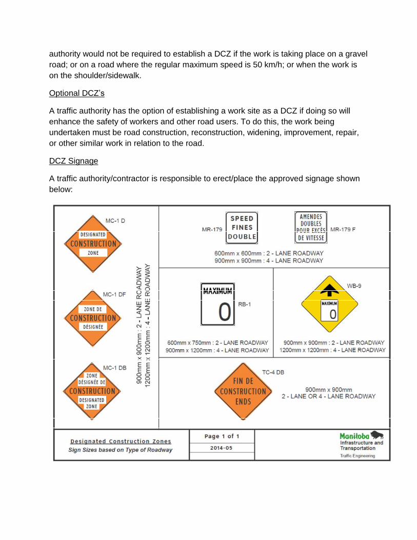
Optional DCZ�s
A traffic authority has the option of establishing a work site as a DCZ if doing so will enhance the safety of workers and other road users. To do this, the work being undertaken must be road construction, reconstruction, widening, improvement, repair, or other similar work in relation to the road.
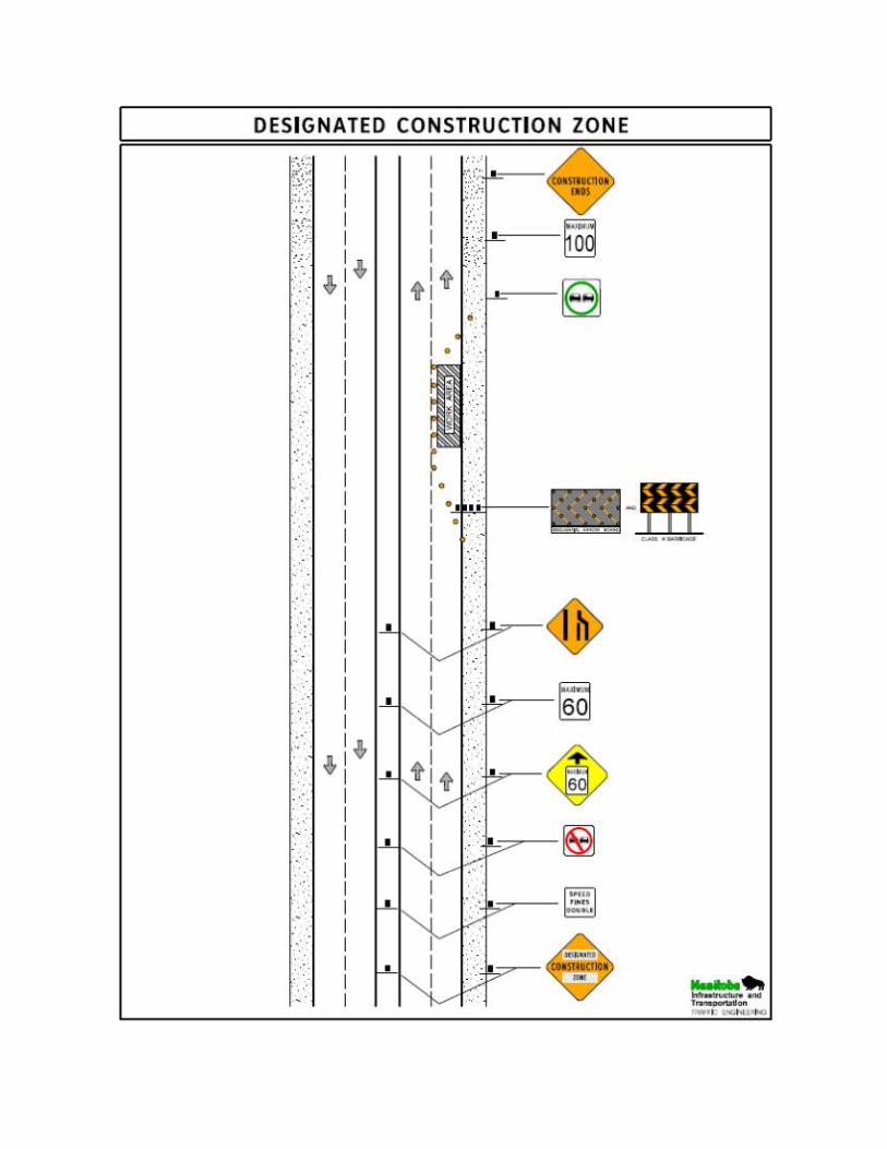
DCZ Signage
A traffic authority/contractor is responsible to erect/place the approved signage shown below:
Designated Construction Zone Sign The beginning of a DCZ must be identified with the �Designated Construction
Zone� sign. Drivers must have an unimpeded view of the sign. This sign will replace the Construction Area sign (MC-1) or the �Men and Equipment Working
sign (TC-2) in the TMP�s and STMP�s contained in this Manual. In accordance with MIT�s Standard Construction Specifications, Construction Area Signs are also to be installed at the intersection of every Provincial Trunk Highway or Provincial Road that enters onto the project.
Construction Ends Sign The end of a DCZ must be marked with the �Construction Ends� sign (TC-4 or TC-4 DB). Drivers must have an unimpeded view of the sign.
Speed Fines Double Warning Sign At least one �Speed Fines Double� sign (MR-179) must be placed within a DCZ and be no more than 150 m after the �Designated Construction Zone� sign which
marks the beginning of the DCZ. A traffic authority/contractor may place more than one �Speed Fines Double� sign
in a DCZ to heighten driver awareness. The sign may also be used to mark a portion of road within the DCZ that intersects with another roadway. For example, where a high volume road intersects with a DCZ, the traffic authority/contractor may use the �Speed Fines Double� sign to warn drivers entering the DCZ. Bilingual Traffic Signing Bilingual Traffic Signing Areas as identified in Policy 900-A-7 of this Manual shall be signed in both official languages using either the bilingual sign, or separate English and French signs with the French sign installed the English sign, at a distance of approximately 30m.
SPEED REDUCTIONS
Only traffic authorities are authorized to approve speed reductions in work zones. A traffic authority may reduce the maximum speed in all or part(s) of a work zone. Longer work zones may have a number of reduced speed areas to enhance the safety of workers and road users. In the past, traffic authorities/contractors commonly used the �60 When Passing
Workers� sign to inform drivers to reduce their speed. This sign, and any similar sign that links a speed reduction to the presence or absence of workers/equipment, is now prohibited from use on all highways throughout Manitoba. As a result Policy 900-C-7 in
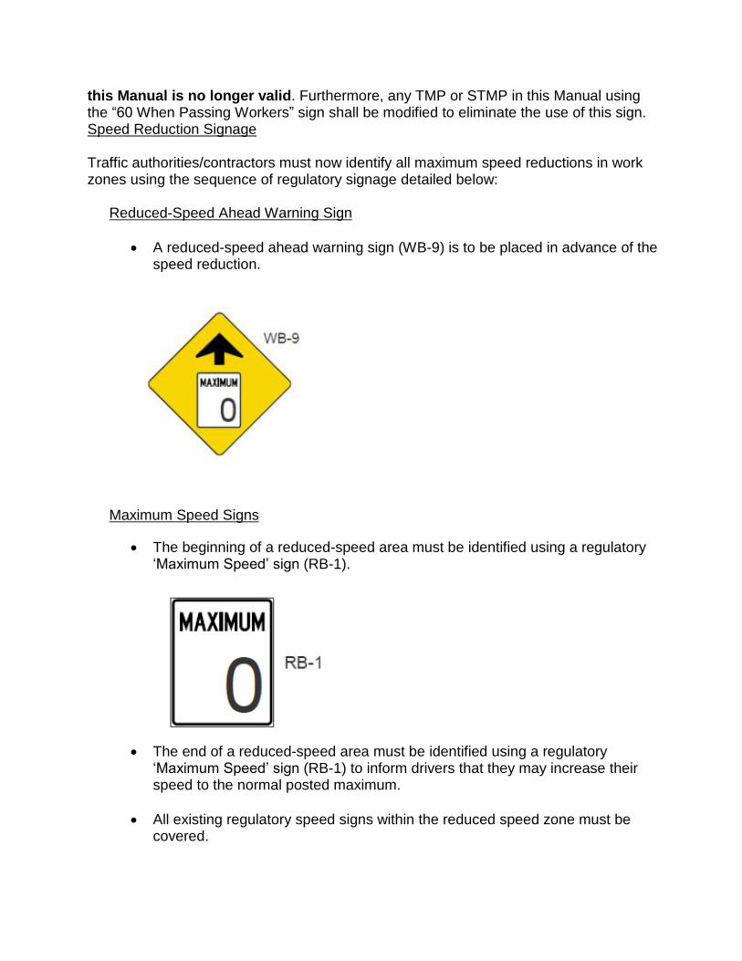
this Manual is no longer valid. Furthermore, any TMP or STMP in this Manual using the �60 When Passing Workers� sign shall be modified to eliminate the use of this sign. Speed Reduction Signage Traffic authorities/contractors must now identify all maximum speed reductions in work zones using the sequence of regulatory signage detailed below:
Reduced-Speed Ahead Warning Sign
A reduced-speed ahead warning sign (WB-9) is to be placed in advance of the speed reduction.
Maximum Speed Signs
The beginning of a reduced-speed area must be identified using a regulatory �Maximum Speed� sign (RB-1).
The end of a reduced-speed area must be identified using a regulatory
�Maximum Speed� sign (RB-1) to inform drivers that they may increase their speed to the normal posted maximum.
All existing regulatory speed signs within the reduced speed zone must be covered.
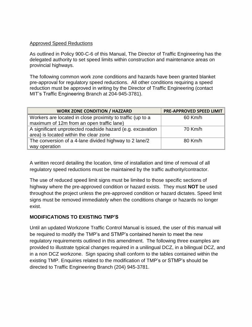
Approved Speed Reductions
As outlined in Policy 900-C-6 of this Manual, The Director of Traffic Engineering has the delegated authority to set speed limits within construction and maintenance areas on provincial highways. The following common work zone conditions and hazards have been granted blanket pre-approval for regulatory speed reductions. All other conditions requiring a speed reduction must be approved in writing by the Director of Traffic Engineering (contact MIT�s Traffic Engineering Branch at 204-945-3781).
WORK ZONE CONDITION / HAZZARD PRE-APPROVED SPEED LIMIT Workers are located in close proximity to traffic (up to a maximum of 12m from an open traffic lane)
60 Km/h
A significant unprotected roadside hazard (e.g. excavation area) is located within the clear zone
70 Km/h
The conversion of a 4-lane divided highway to 2 lane/2 way operation
80 Km/h
A written record detailing the location, time of installation and time of removal of all regulatory speed reductions must be maintained by the traffic authority/contractor.
The use of reduced speed limit signs must be limited to those specific sections of highway where the pre-approved condition or hazard exists. They must NOT be used throughout the project unless the pre-approved condition or hazard dictates. Speed limit signs must be removed immediately when the conditions change or hazards no longer exist.
MODIFICATIONS TO EXISTING TMP�S
Until an updated Workzone Traffic Control Manual is issued, the user of this manual will be required to modify the TMP�s and STMP�s contained herein to meet the new regulatory requirements outlined in this amendment. The following three examples are provided to illustrate typical changes required in a unilingual DCZ, in a bilingual DCZ, and in a non DCZ workzone. Sign spacing shall conform to the tables contained within the existing TMP. Enquiries related to the modification of TMP�s or STMP�s should be
directed to Traffic Engineering Branch (204) 945-3781.
CONSTRUCTION
CONSTRUCTION
AREA
ENDS
and
Provincial Trunk Highways
Provincial Roads
EDITION 2013
Infrastructure andTransportation
Traffic Engineering
Work Zone Traffic Control Manual
MAXIMUM
60WHEN
PASSINGWORKERS
Manitoba Infrastructure and Transportation
DRA
FT
rev. March 2011
INTRODUCTION
WORK ZONE TRAFFIC CONTROL MANUAL This manual is intended to provide minimum standards for the protection of road users and workers during temporary works relating to highway maintenance and construction, including utility and other operations. This manual should provide a single source for traffic control standards for use on Manitoba’s highways. Over 1000 “hard copies” of this manual were circulated since its initial printing in 2000. It has been available “on line” since March 2002. Please contact the Traffic Engineering Branch at (204) 945-3781 for advice and recommendations on dealing with traffic control situations not included in this manual, or where the standards in the manual fail to adequately control traffic or protect workers. The following revised standards are based on best practices in Manitoba and in other jurisdictions. They have been revised, refined and adjusted in actual field use. However, they are meant to be open to change and improvement, and we continue to welcome your suggestions, comments and criticisms. Traffic controls for temporary conditions often represent a compromise between the time and cost to erect and maintain the necessary devices, and the need to get the job done. We hope this manual strikes a balance between those conflicting requirements, while providing the necessary protection to both workers and motorists. This 2011 Revision incorporates a few changes and improvements. Director, Traffic Engineering Branch
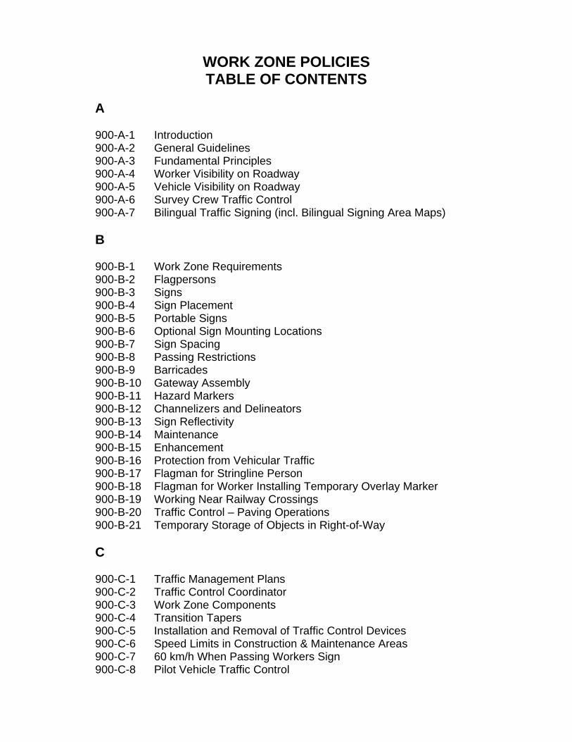
WORK ZONE POLICIES TABLE OF CONTENTS
A 900-A-1 Introduction 900-A-2 General Guidelines 900-A-3 Fundamental Principles 900-A-4 Worker Visibility on Roadway 900-A-5 Vehicle Visibility on Roadway 900-A-6 Survey Crew Traffic Control 900-A-7 Bilingual Traffic Signing (incl. Bilingual Signing Area Maps) B 900-B-1 Work Zone Requirements 900-B-2 Flagpersons 900-B-3 Signs 900-B-4 Sign Placement 900-B-5 Portable Signs 900-B-6 Optional Sign Mounting Locations 900-B-7 Sign Spacing 900-B-8 Passing Restrictions 900-B-9 Barricades 900-B-10 Gateway Assembly 900-B-11 Hazard Markers 900-B-12 Channelizers and Delineators 900-B-13 Sign Reflectivity 900-B-14 Maintenance 900-B-15 Enhancement 900-B-16 Protection from Vehicular Traffic 900-B-17 Flagman for Stringline Person 900-B-18 Flagman for Worker Installing Temporary Overlay Marker 900-B-19 Working Near Railway Crossings 900-B-20 Traffic Control – Paving Operations 900-B-21 Temporary Storage of Objects in Right-of-Way C 900-C-1 Traffic Management Plans 900-C-2 Traffic Control Coordinator 900-C-3 Work Zone Components 900-C-4 Transition Tapers 900-C-5 Installation and Removal of Traffic Control Devices 900-C-6 Speed Limits in Construction & Maintenance Areas 900-C-7 60 km/h When Passing Workers Sign 900-C-8 Pilot Vehicle Traffic Control
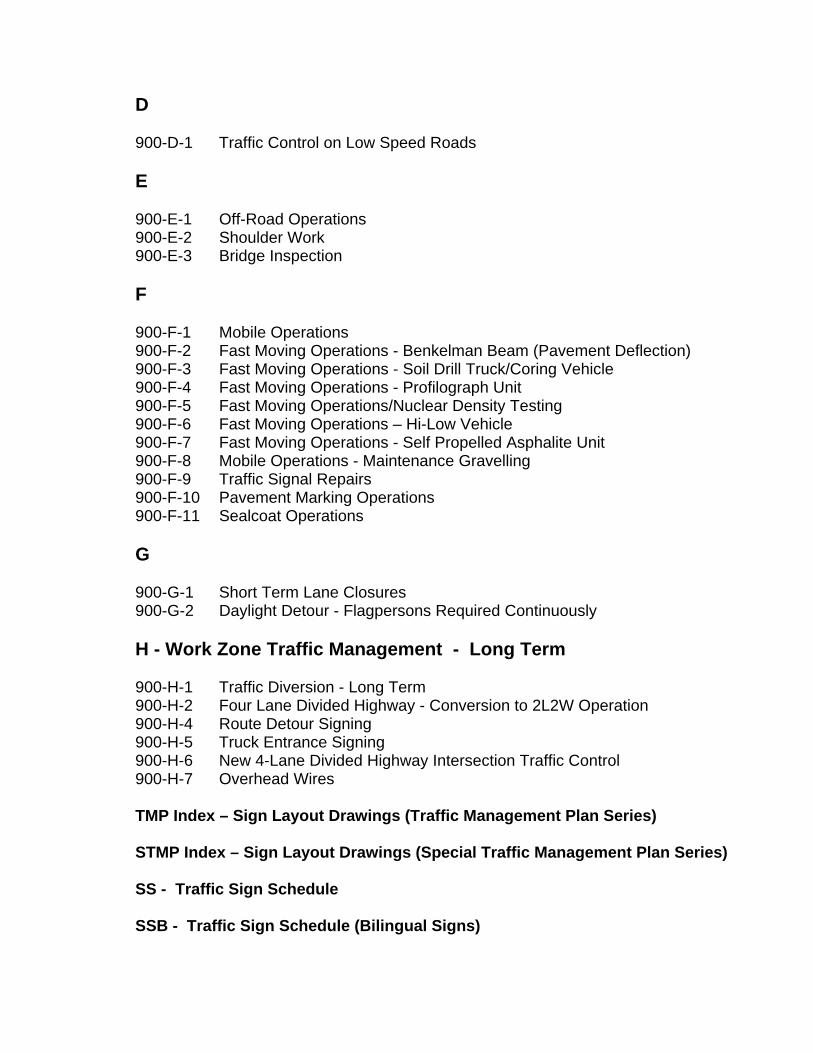
D 900-D-1 Traffic Control on Low Speed Roads E 900-E-1 Off-Road Operations 900-E-2 Shoulder Work 900-E-3 Bridge Inspection F 900-F-1 Mobile Operations 900-F-2 Fast Moving Operations - Benkelman Beam (Pavement Deflection) 900-F-3 Fast Moving Operations - Soil Drill Truck/Coring Vehicle 900-F-4 Fast Moving Operations - Profilograph Unit 900-F-5 Fast Moving Operations/Nuclear Density Testing 900-F-6 Fast Moving Operations – Hi-Low Vehicle 900-F-7 Fast Moving Operations - Self Propelled Asphalite Unit 900-F-8 Mobile Operations - Maintenance Gravelling 900-F-9 Traffic Signal Repairs 900-F-10 Pavement Marking Operations 900-F-11 Sealcoat Operations G 900-G-1 Short Term Lane Closures 900-G-2 Daylight Detour - Flagpersons Required Continuously H - Work Zone Traffic Management - Long Term 900-H-1 Traffic Diversion - Long Term 900-H-2 Four Lane Divided Highway - Conversion to 2L2W Operation 900-H-4 Route Detour Signing 900-H-5 Truck Entrance Signing 900-H-6 New 4-Lane Divided Highway Intersection Traffic Control 900-H-7 Overhead Wires TMP Index – Sign Layout Drawings (Traffic Management Plan Series) STMP Index – Sign Layout Drawings (Special Traffic Management Plan Series) SS - Traffic Sign Schedule SSB - Traffic Sign Schedule (Bilingual Signs)
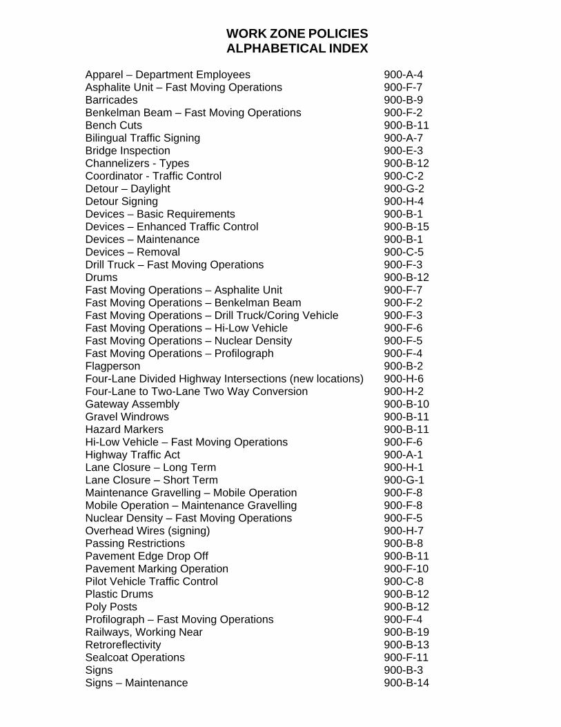
WORK ZONE POLICIES ALPHABETICAL INDEX
Apparel – Department Employees 900-A-4 Asphalite Unit – Fast Moving Operations 900-F-7 Barricades 900-B-9 Benkelman Beam – Fast Moving Operations 900-F-2 Bench Cuts 900-B-11 Bilingual Traffic Signing 900-A-7 Bridge Inspection 900-E-3 Channelizers - Types 900-B-12 Coordinator - Traffic Control 900-C-2 Detour – Daylight 900-G-2 Detour Signing 900-H-4 Devices – Basic Requirements 900-B-1 Devices – Enhanced Traffic Control 900-B-15 Devices – Maintenance 900-B-1 Devices – Removal 900-C-5 Drill Truck – Fast Moving Operations 900-F-3 Drums 900-B-12 Fast Moving Operations – Asphalite Unit 900-F-7 Fast Moving Operations – Benkelman Beam 900-F-2 Fast Moving Operations – Drill Truck/Coring Vehicle 900-F-3 Fast Moving Operations – Hi-Low Vehicle 900-F-6 Fast Moving Operations – Nuclear Density 900-F-5 Fast Moving Operations – Profilograph 900-F-4 Flagperson 900-B-2 Four-Lane Divided Highway Intersections (new locations) 900-H-6 Four-Lane to Two-Lane Two Way Conversion 900-H-2 Gateway Assembly 900-B-10 Gravel Windrows 900-B-11 Hazard Markers 900-B-11 Hi-Low Vehicle – Fast Moving Operations 900-F-6 Highway Traffic Act 900-A-1 Lane Closure – Long Term 900-H-1 Lane Closure – Short Term 900-G-1 Maintenance Gravelling – Mobile Operation 900-F-8 Mobile Operation – Maintenance Gravelling 900-F-8 Nuclear Density – Fast Moving Operations 900-F-5 Overhead Wires (signing) 900-H-7 Passing Restrictions 900-B-8 Pavement Edge Drop Off 900-B-11 Pavement Marking Operation 900-F-10 Pilot Vehicle Traffic Control 900-C-8 Plastic Drums 900-B-12 Poly Posts 900-B-12 Profilograph – Fast Moving Operations 900-F-4 Railways, Working Near 900-B-19 Retroreflectivity 900-B-13 Sealcoat Operations 900-F-11 Signs 900-B-3 Signs – Maintenance 900-B-14
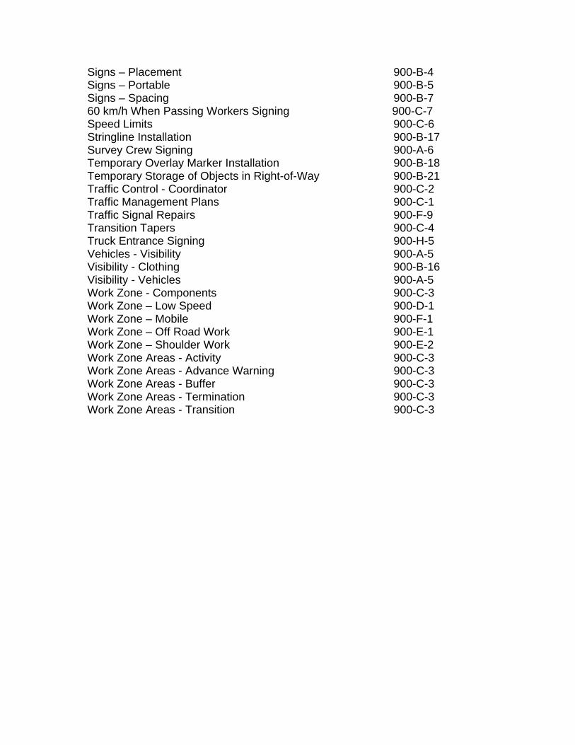
Signs – Placement 900-B-4 Signs – Portable 900-B-5 Signs – Spacing 900-B-7 60 km/h When Passing Workers Signing 900-C-7 Speed Limits 900-C-6 Stringline Installation 900-B-17 Survey Crew Signing 900-A-6 Temporary Overlay Marker Installation 900-B-18 Temporary Storage of Objects in Right-of-Way 900-B-21 Traffic Control - Coordinator 900-C-2 Traffic Management Plans 900-C-1 Traffic Signal Repairs 900-F-9 Transition Tapers 900-C-4 Truck Entrance Signing 900-H-5 Vehicles - Visibility 900-A-5 Visibility - Clothing 900-B-16 Visibility - Vehicles 900-A-5 Work Zone - Components 900-C-3 Work Zone – Low Speed 900-D-1 Work Zone – Mobile 900-F-1 Work Zone – Off Road Work 900-E-1 Work Zone – Shoulder Work 900-E-2 Work Zone Areas - Activity 900-C-3 Work Zone Areas - Advance Warning 900-C-3 Work Zone Areas - Buffer 900-C-3 Work Zone Areas - Termination 900-C-3 Work Zone Areas - Transition 900-C-3
Policy/Standard No. 900-A-1
Effective Date: April 15, 1997
Traffic Control Device: Work Zone Date of Revision: March 15, 2002 Division: Subject: Introduction Page 1 of 3 Purpose The Manitoba Infrastructure and Transportation provides uniform policies and standards for traffic control devices in work zones on or adjacent to Provincial Trunk Highways and Provincial Roads. Traffic control devices include signs, delineators, channelizers, barricades, pavement markings, lighting devices, flagpersons/flagging equipment, and any other device placed upon a public roadway which warns motorists of changing conditions or provides for the safe movement of traffic. All organizations performing work on or adjacent to a highway are required to install and maintain such traffic control devices as identified in this policy/standard as necessary to provide a safe work environment and ensure safe passage for the travelling public.
Policy All employees, contractors, and utilities doing work on or adjacent to Provincial Trunk Highways and Provincial Roads are required to implement and maintain a Work Zone Traffic Management Plan consistent with the Policies and Standards outlined herein.
Standard The standards contained herein are minimum standards and may have to be increased to accommodate traffic safely. Modifications must be approved by the Director of Traffic Engineering or his representative before plans are implemented in the field to ensure that the safety of workers and motorists is not compromised. Driver Expectations Primarily because of driver expectations, safety in construction and maintenance zones is difficult to achieve effectively. Although most motorists understand that unusual roadway conditions may be encountered, the general expectation is that evasive actions or significant reductions in vehicle speed will not be required. RECOMMENDED: “ORIGINAL SIGNED BY” APPROVED: “ORIGINAL SIGNED BY” Director, Traffic Engineering Executive Director Highway Engineering
Policy/Standard No. 900-A-1
Page 2 of 3
While maintenance and construction activities can be unexpected, most maintenance and construction zones are relatively static, providing the traffic authority with the opportunity to provide effective warning or guidance through the zone. Effectiveness of Traffic Control Devices For the most part, this warning or guidance can be provided through the use of standard traffic control devices. To achieve optimum effectiveness, the traffic control at all maintenance and construction zones must be regularly reviewed and enhanced where required: Motorist safety is generally most compromised in construction and maintenance zones during hours of darkness. Consequently, the adequacy of traffic controls in these areas, particularly detours, must be regularly reviewed, especially at night to ensure that the intended traffic control is not compromised. This review should include an assessment of: sign reflectivity sign lateral, longitudinal and vertical position relationships between other temporary or permanent traffic control devices Only those temporary signs and devices that are approved by the Department may be used on the highway right-of-way. All signs and devices must be reflectorized to show the same colour by night as by day, and the reflectivity levels must be maintained by cleaning or replacing signs, etc. when necessary. Special emphasis is required when a speed drop greater than 30 km/h is encountered, between the normal highway travel speed and the speed necessary to smoothly and safely traverse a detour or construction area. Positive Guidance Where possible, positive guidance (pavement markings, plastic drums, cones, delineation, etc.) must be provided through a work area or detour. Under all circumstances this positive guidance should always create a consistent visual image. This is created by ensuring both uniform spacing and uniform offsets of the delineators/channelizers. If uniform offsets are not possible, smooth transitions from one offset to another must be used to avoid abrupt changes in the visual roadway alignment. As oncoming headlights may obscure the change in alignment, special emphasis such as illumination, positive guidance, or flashing arrow boards may be required at the transition from four-lane divided to a two-lane two-way (2L2W) highway where a change in alignment occurs.
Policy/Standard No. 900-A-1
Page 3 of 3 To obtain adequate impact, under some circumstances, traffic control devices (signs, pavement markings, etc.) may be enhanced by: oversizing signs supplementing with fluorescent orange flags removing unnecessary existing signs (route markers, guide signs, etc.) roadway illumination Under some circumstances, the existing speed limit signs in the work area should be removed or covered. When one side of a divided highway is closed and the other side is used to carry two-lane, two-way (2L2W) traffic, the opposing traffic flows must be separated from each other by some form of a physical barrier such as cones, delineator posts, plastic drums or portable concrete barriers or plastic water-filled barriers. Requirements of The Highway Traffic Act (HTA): Section 74 - "All contractors' and Department vehicles, unless physically engaged in
maintaining or constructing a highway, must comply at all times with the rules of the road as established in The Highway Traffic Act."
Section 77(7) - "The closest construction traffic control device shall not be further than
450 m from the start of the work area." Section 77(9) - "Construction traffic control devices shall be removed when the work is
sufficiently completed to render it unnecessary for the devices to remain in place." Section 81 - Only those traffic control devices approved by the Highway Traffic Board or
by the Director of Traffic Engineering may be used on provincial highways. Lane Widths Detours with travel speeds of 70 km/h or greater should have clear lane widths of at least 3.7 m, excluding shoulders.
Policy/Standard No. 900-A-2
Effective Date: April 15, 1997
Traffic Control Device: Work Zone Date of Revision: March 15, 2002 Division: Subject: General Guidelines Page 1 of 2 Purpose The Policies and Standards developed herein establish guidelines to be observed in developing Traffic Management Plans (TMP) for construction and maintenance work zones. These guidelines are directed to the safe and expeditious movement of traffic through construction and maintenance work zones and to the safety of the workforce performing the operations. The Policies/Standards also sets forth guidelines pertaining to the use, installation, and maintenance of the various traffic control devices required for roadway construction, maintenance, and utility work, and prescribes standards where possible. These guidelines deal with signs, delineators, channelizers, barricades, pavement markings, lighting devices, and flagpersons/ flagging equipment. Several typical situations are included in the Policies/Standards that illustrate the proper application of standard traffic control devices.
Policy The Policies and Standards developed herein must be used as the primary guide in developing Traffic Management Plans for construction and maintenance work zones. The requirements of future Departmental policy directives, statutory/regulatory provisions, and requirements detailed in specifications of work by contract will override these basic guidelines as applicable. The users of these Policies/Standards are responsible for being aware of any special considerations or requirements pertaining to particular situations.
Standard Since it is not practical to prescribe detailed application standards for all situations that may arise, it is emphasized that only minimum desirable standards for normal situations are presented. When unusual or hazardous conditions prevail, Traffic Engineering Branch must be consulted before changes are made to Traffic Management Plans. RECOMMENDED: “ORIGINAL SIGNED BY” APPROVED: “ORIGINAL SIGNED BY” Director, Traffic Engineering Executive Director Highway Engineering
Policy/Standard No. 900-A-2
Page 2 of 2 The general guidelines outlined in the Policies/Standards are applicable to all Provincial Trunk Highways and Provincial Roads. However, the traffic control devices guidelines must be interpreted with respect to the specific traffic characteristics of each location. The level of work zone protection should be based on roadway speed, traffic volume, available sight distance, duration of operation, and hazard exposure. Traffic conditions in urban areas are generally characterized by low speeds, wide ranges of traffic volume, limited manoeuvring room, frequent turns and cross movements, pedestrian traffic, and other obstructions. Rural highways are typically characterized by higher speeds, lower volumes, greater manoeuvring room and less interference from turning vehicles, pedestrians, and encroachments. Although each situation must be dealt with individually, conformity with the general provisions established herein is required. Whenever possible, identical conditions should be similarly treated. Minor variations may be necessary due to field conditions or other governing factors. In such instances, engineering judgement must be used to select the most appropriate devices.
Policy/Standard No. 900-A-3
Effective Date: April 15, 1997
Traffic Control Device: Work Zone Date of Revision: March 15, 2002 Division: Subject: Fundamental Principles Page 1 of 3 Purpose Construction and maintenance work zones often present the motorist with unexpected or unusual situations. Consequently, special care must be taken when applying traffic management techniques to these areas. The following principles and procedures contribute to the safety of motorists and workers in construction and maintenance work zones.
Policy All employees, contractors and utilities doing work on, or adjacent to, highways are required to follow this set of Fundamental Principles when establishing Work Zone Traffic Management Plans.
Standard Traffic Safety Traffic safety in work zones must be an integral and high priority element of every project from planning through to completion of the work. The safety of motorists, pedestrians, and workers must be kept in mind at all times. The safety principles governing the design of permanent roadways should also govern the design of construction and maintenance sites. The objective should be to route traffic through the work zone using geometry and traffic control devices comparable to those used in normal highway situations. A Traffic Management Plan (TMP), in sufficient detail to reflect the complexity of the work project, must be prepared, understood by all responsible parties, and put into operation before the site is occupied. Construction equipment or vehicles must not be parked so as to obscure or in any way block motorists' view of traffic control devices. Vehicles may only be parked on the roadway if they are being used in the performance of the work. RECOMMENDED: “ORIGINAL SIGNED BY” APPROVED: “ORIGINAL SIGNED BY” Director, Traffic Engineering Executive Director Highway Engineering
Policy/Standard No. 900-A-3
Page 2 of 3
The travelled way must be kept free of foreign objects such as spilled earth, rock, timber, and other items that may fall from construction vehicles. Materials spilled near or dropped along or across any public travelled roadway must be removed immediately. Traffic must be channelized with pavement markings, traffic cones, flexible posts, breakaway posts, and other lightweight devices that yield when struck. To accommodate errant vehicles or emergencies, construction equipment, material and debris must be stored so as to provide an unobstructed roadside recovery area, as wide as practicable. Traffic Movement To minimize the disruption of service, traffic movement through work zones should be inhibited as little as possible. Reduced speed zoning should be avoided as much as possible and must be verified by a traffic engineering analysis. Abrupt or frequent changes in geometry such as lane narrowing, dropped lanes or transitions that require rapid manoeuvres should be avoided. Except as specified in the TMP, the width and number of lanes available to traffic must not be reduced. Construction time should be minimized to reduce motorist exposure to potential hazards. Motorist Guidance Motorists should be guided in a clear and understandable manner while approaching and traversing construction and maintenance work zones. Adequate warning, delineation and channelization through the use of appropriate traffic control devices must be provided to assure the motorist of positive guidance throughout the work zone. The traffic control devices must be effective under varying conditions of light and weather to ensure traffic guidance is maintained at all times. For both long and short duration construction and maintenance projects, inappropriate traffic control devices must be covered or removed to avoid misleading the motorist. On projects of less than several days duration, existing pavement markings may be left in place, but only if the intended vehicle paths can be properly delineated. Flagging procedures, when used, provide positive guidance to the motorist when travelling through the work zone. The complexity of the work being performed and the TMP will dictate the use of flagpersons.
Policy/Standard No. 900-A-3
Page 3 of 3 Operations Work zones must be regularly monitored under varying conditions of traffic volume, light, and weather to ensure that traffic management measures are operating effectively and that all traffic control devices are clearly visible, clean, and in good repair. Work zone accident records must be maintained and periodically analyzed to help identify conflicts and to guide officials in improving operations. During periods of inactivity, including nights, weekends, and holidays, traffic control devices not required for traffic management must be covered or removed. All traffic control devices must be removed when no longer applicable.
Policy/Standard No. 900-A-4
Effective Date: April 15, 1997
Traffic Control Device: Work Zone Date of Revision: March 15, 2005 Division: Subject: Worker Visibility on Roadway Page 1 of 1 Purpose All Manitoba Infrastructure and Transportation workers who are on the highway or on the right-of-way are exposed to the dangers of traffic. The key to maximum safety while on the roadway is visibility.
Policy All employees of the Department are required to wear Department approved high visibility clothing or approved flagperson's vest and hat whenever they may be exposed to traffic or construction equipment.
Standard Every employee of the Department who is exposed to traffic will be provided with and wear high-visibility safety apparel that complies with the requirements of CSA Standard Z96-02 High-Visibility Safety Apparel. This safety equipment must be worn at all times when employees are in a situation where they may be exposed to traffic. Employees have the option to purchase other Department approved high visibility clothing. RECOMMENDED: “ORIGINAL SIGNED BY” APPROVED: “ORIGINAL SIGNED BY” Director, Traffic Engineering Executive Director Highway Engineering
Policy/Standard No. 900-A-5
Effective Date: April 15, 1997
Traffic Control Device: Work Zone Date of Revision: March 15, 2002 Division: Subject: Vehicle Visibility on Roadway Page 1 of 1 Purpose All construction and maintenance vehicles that are parked on the highway or on the right-of-way create a hazard for motorists. The key to maximum safety while on the roadway is visibility.
Policy All vehicles of the Manitoba Infrastructure and Transportation, contractors, consultants, or utility companies that are required to park on the road in order for the users to conduct operations on the highway must be equipped with visibility enhancing lighting as defined by Mechanical Equipment Services.
Standard Every vehicle of the Department, contractors, or utility companies that may be exposed to traffic must be equipped with an approved lighting system. This safety equipment must be in use at all times when the vehicle is in a situation where it might pose a hazard to motorists. Individual Regions or Branches may choose to provide vehicles with higher standard lighting systems for the vehicles in their fleet based on the frequency and nature of exposure. RECOMMENDED: “ORIGINAL SIGNED BY” APPROVED: “ORIGINAL SIGNED BY” Director, Traffic Engineering Executive Director Highway Engineering
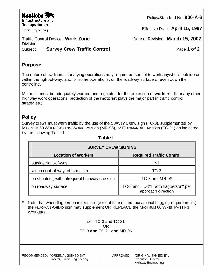
Policy/Standard No. 900-A-6
Effective Date: April 15, 1997
Traffic Control Device: Work Zone Date of Revision: March 15, 2002 Division: Subject: Survey Crew Traffic Control Page 1 of 2 Purpose The nature of traditional surveying operations may require personnel to work anywhere outside or within the right-of-way, and for some operations, on the roadway surface or even down the centreline. Motorists must be adequately warned and regulated for the protection of workers. (In many other highway work operations, protection of the motorist plays the major part in traffic control strategies.)
Policy Survey crews must warn traffic by the use of the SURVEY CREW sign (TC-3), supplemented by MAXIMUM 60 WHEN PASSING WORKERS sign (MR-96), or FLAGMAN AHEAD sign (TC-21) as indicated by the following Table I. Table I
SURVEY CREW SIGNING
Location of Workers
Required Traffic Control
outside right-of-way
Nil
within right-of-way, off shoulder
TC-3
on shoulder, with infrequent highway crossing
TC-3 and MR-96
on roadway surface
TC-3 and TC-21, with flagperson* per
approach direction
* Note that when flagperson is required (except for isolated, occasional flagging requirements)
the FLAGMAN AHEAD sign may supplement OR REPLACE the MAXIMUM 60 WHEN PASSING
WORKERS. i.e. TC-3 and TC-21 OR TC-3 and TC-21 and MR-96 RECOMMENDED: “ORIGINAL SIGNED BY” APPROVED: “ORIGINAL SIGNED BY: Director, Traffic Engineering Executive Director Highway Engineering
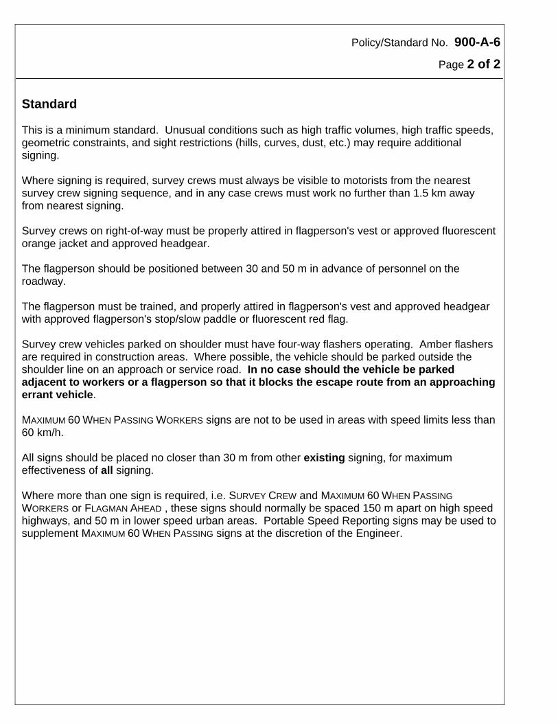
Policy/Standard No. 900-A-6
Page 2 of 2 Standard This is a minimum standard. Unusual conditions such as high traffic volumes, high traffic speeds, geometric constraints, and sight restrictions (hills, curves, dust, etc.) may require additional signing. Where signing is required, survey crews must always be visible to motorists from the nearest survey crew signing sequence, and in any case crews must work no further than 1.5 km away from nearest signing. Survey crews on right-of-way must be properly attired in flagperson's vest or approved fluorescent orange jacket and approved headgear. The flagperson should be positioned between 30 and 50 m in advance of personnel on the roadway. The flagperson must be trained, and properly attired in flagperson's vest and approved headgear with approved flagperson's stop/slow paddle or fluorescent red flag. Survey crew vehicles parked on shoulder must have four-way flashers operating. Amber flashers are required in construction areas. Where possible, the vehicle should be parked outside the shoulder line on an approach or service road. In no case should the vehicle be parked adjacent to workers or a flagperson so that it blocks the escape route from an approaching errant vehicle. MAXIMUM 60 WHEN PASSING WORKERS signs are not to be used in areas with speed limits less than 60 km/h. All signs should be placed no closer than 30 m from other existing signing, for maximum effectiveness of all signing. Where more than one sign is required, i.e. SURVEY CREW and MAXIMUM 60 WHEN PASSING
WORKERS or FLAGMAN AHEAD , these signs should normally be spaced 150 m apart on high speed highways, and 50 m in lower speed urban areas. Portable Speed Reporting signs may be used to supplement MAXIMUM 60 WHEN PASSING signs at the discretion of the Engineer.
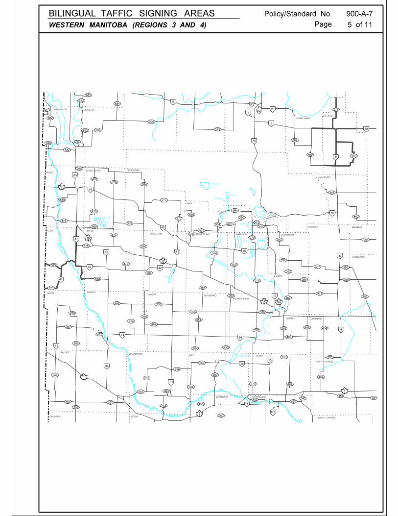
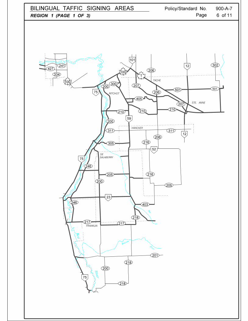
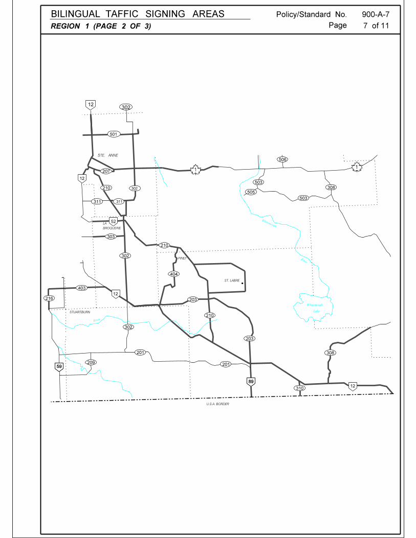
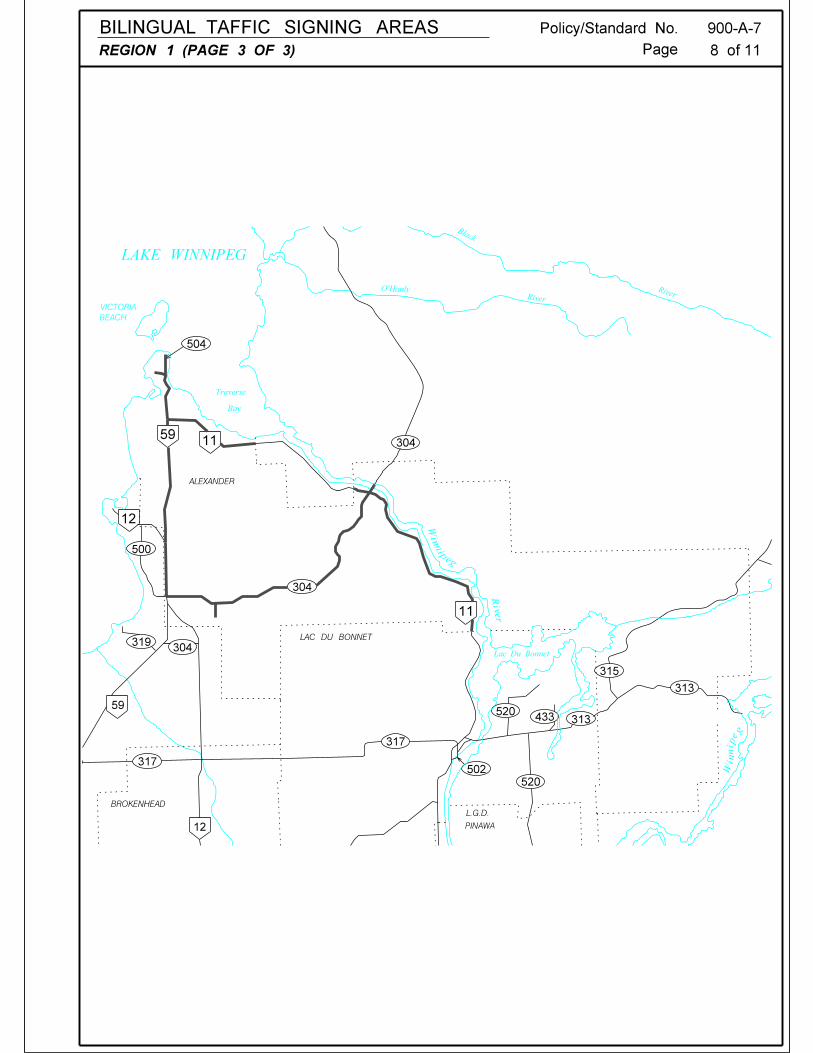
Policy/Standard No. 900-A-7
Effective Date: March 1, 2000
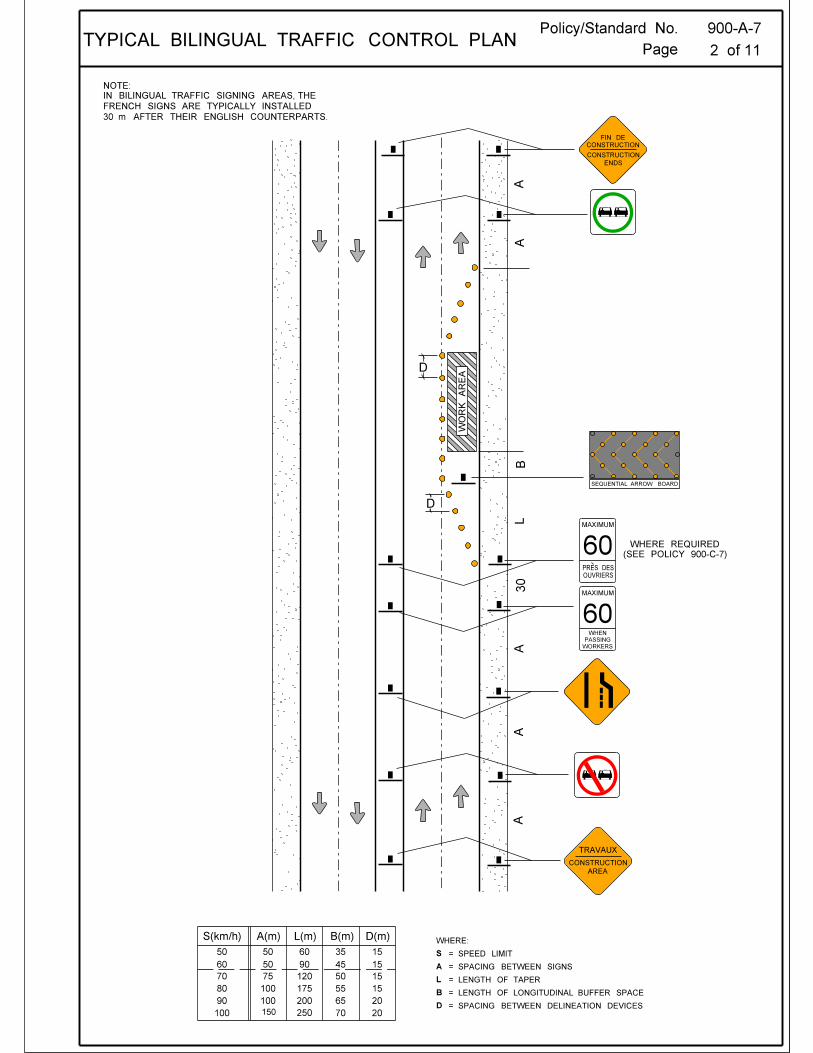
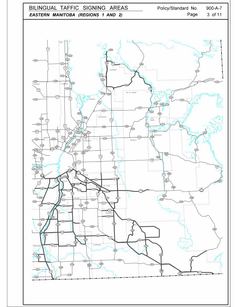
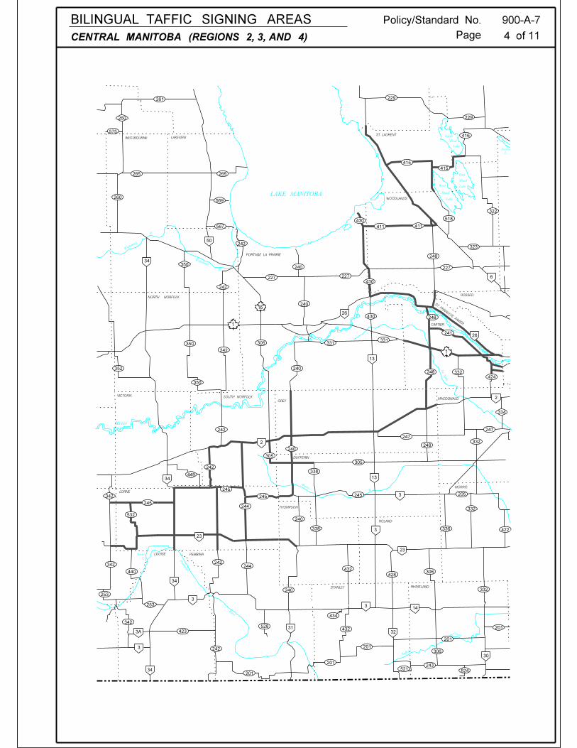
Traffic Control Device: Work Zone Date of Revision: March 15, 2002 Division: Subject: Bilingual Traffic Signing Page 1 of 11 Purpose The province's French Language Services Policy includes a commitment to provide bilingual (English/French) traffic signing for motorists on specified provincial routes.
Policy Department construction and maintenance projects will include the use of bilingual highway construction signs on all Provincial Trunk Highways and Provincial Roads that lie within the "Bilingual Traffic Signing area" in Manitoba. Generally, all of the highway construction signs with verbal messages will be affected by this policy. The French sign shall be installed behind the English sign, at a distance of approximately 30 m. RECOMMENDED: APPROVED: Director, Traffic Engineering Executive Director Highway Engineering
Policy/Standard No. 900-B-1
Effective Date: April 15, 1997
Traffic Control Device: Work Zone Date of Revision: March 15, 2002 Division: Subject: Requirements Page 1 of 3 Purpose A traffic control device is any device placed upon, over or adjacent to a roadway that is intended to regulate, warn or guide motorists and provide for the orderly movement of traffic. In construction and maintenance work zones, traffic control devices are used to ensure safe passage for the travelling public through or around the work area, and to safeguard the personnel involved in the work. Traffic control devices include signs, delineators, channelizers, barricades, pavement markings, lighting devices, flagperson/flagging equipment, and any other device placed upon a public roadway which warns motorists of dangerous conditions or provide for the safe movement of traffic.
Policy Only those devices that are approved by the Manitoba Infrastructure and Transportation may be used on provincial highway projects. Traffic Engineering Branch must be contacted before any non-standard traffic control device is placed on the road.
Standard Basic Requirements To be effective, a traffic control device must meet five basic requirements: fulfill a need command attention convey a clear, simple message command the respect of motorists give adequate time for proper response Five basic considerations are employed to ensure that these requirements are met: device design uniformity placement application maintenance
RECOMMENDED: “ORIGINAL SIGNED BY” APPROVED: “ORIGINAL SIGNED BY” Director, Traffic Engineering Executive Director Highway Engineering
Policy/Standard No. 900-B-1
Page 2 of 3
Device Design The following design elements must be considered when selecting traffic control devices: size shape colour(s) contrast composition reflectivity message simplicity message legibility These design elements combine in various ways to influence how effectively a device meets the basic traffic control device requirements. Device Uniformity Traffic control device uniformity aids in recognition, interpretation and message comprehension, simplifying the task of the motorist. Uniformity applies not only to the design of traffic control devices but also to how the devices are used. A standard device used inappropriately is as objectionable as a non-standard device. Misuse can result in disrespect for the standard device at locations where it is needed. Uniformity also reduces the costs associated with device manufacture, installation, maintenance, and administration. Minor modifications of a specified device may be allowed due to necessity. However, the essential device characteristics must be maintained. The Uniform Traffic Control Devices for Canada (UTCD) manual should be used as a resource document to help ensure uniformity. Device Placement Traffic control devices should be placed within the cone of vision of the motorist (approximately 10 degrees from the roadway alignment) so that they command attention. Devices must be located with respect to the point, object or situation to which they apply to aid in conveying the proper meaning. Device location, combined with legibility, must allow for an adequate response time from motorists travelling at normal speeds. Traffic control devices must be spaced far enough apart to allow a motorist to respond correctly to each in turn, while avoiding rapid or sudden reactions which could cause loss of control. Device Application Device application should ensure that sufficient and applicable devices and related equipment are installed to meet the traffic requirements at any given location. The motorist must be guided into and through the work zone by a series of signs and devices which give the driver an opportunity to adjust to upcoming conditions. Devices must be installed only if they are necessary; unnecessary traffic control devices contribute to work zone "clutter" and detract from those that are needed.
Policy/Standard No. 900-B-1
Page 3 of 3 Devices must be applied in a uniform and consistent manner. This uniformity allows motorists to anticipate traffic control situations similar to those previously experienced, and helps to ensure they respond properly. Due to decreased visibility, motorist safety is compromised more at night than during the day. Therefore, traffic control in work zones, particularly detours with speed drops greater than 30 km/h, must be assessed at night as well as during the day to determine the adequacy of the traffic control devices. The following factors influence how well a system of traffic control devices performs at night:
device condition size reflectivity enhancements longitudinal position lateral position the "total effect"
The most important factor is the relationship between traffic control devices and other construction and/or permanent devices, i.e., the "total effect". A work zone where the traffic control is relatively straightforward during the day may become quite confusing to motorists at night. The clutter of reflectorized signs, delineators, and barricades can make it difficult to travel through a work zone safely. If work zone traffic control must be left in place overnight, any permanent or temporary devices that are not needed and may tend to confuse motorists must be covered or removed. Special emphasis involving positive guidance, illumination and/or sequential flashers may be required at transitions from four-lane divided highways to two-lane roadways. Device Maintenance Maintenance of traffic control devices can be divided into two types - Physical and Functional:
Physical Maintenance - All traffic control devices used in construction and maintenance work zones must be maintained to high standards to ensure that visibility and legibility are retained both day and night. Clean, legible, properly installed devices in good working condition command the respect of motorists. Traffic control devices must be monitored to ensure their satisfactory condition, and if necessary, must be immediately repaired or replaced. If traffic control devices are left in place overnight, inspections must be performed periodically to ensure that nighttime reflective levels are adequate. Traffic control devices with inadequate reflective levels must be immediately replaced.
Functional Maintenance - Functional Maintenance involves adjusting traffic control devices to changes in work zone conditions. When operations cease due to darkness or a change in the sequence of the work, only those traffic control devices necessary to protect motorists must remain in place. Devices which are no longer applicable must be removed or replaced. Functional maintenance includes ensuring that the system of traffic control devices operates as specified in the Traffic Management Plans. This includes making sure that only those traffic control devices approved by the Department are used and that no obsolete, inappropriate or otherwise objectionable devices are installed.
Policy/Standard No. 900-B-2
Effective Date: 1995
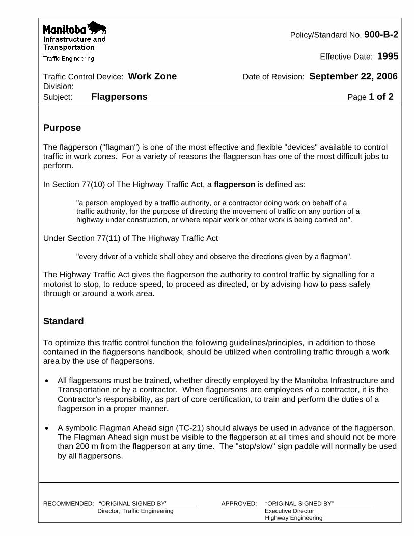
Traffic Control Device: Work Zone Date of Revision: September 22, 2006 Division: Subject: Flagpersons Page 1 of 2 Purpose The flagperson ("flagman") is one of the most effective and flexible "devices" available to control traffic in work zones. For a variety of reasons the flagperson has one of the most difficult jobs to perform. In Section 77(10) of The Highway Traffic Act, a flagperson is defined as:
"a person employed by a traffic authority, or a contractor doing work on behalf of a traffic authority, for the purpose of directing the movement of traffic on any portion of a highway under construction, or where repair work or other work is being carried on".
Under Section 77(11) of The Highway Traffic Act
"every driver of a vehicle shall obey and observe the directions given by a flagman". The Highway Traffic Act gives the flagperson the authority to control traffic by signalling for a motorist to stop, to reduce speed, to proceed as directed, or by advising how to pass safely through or around a work area.
Standard To optimize this traffic control function the following guidelines/principles, in addition to those contained in the flagpersons handbook, should be utilized when controlling traffic through a work area by the use of flagpersons. All flagpersons must be trained, whether directly employed by the Manitoba Infrastructure and
Transportation or by a contractor. When flagpersons are employees of a contractor, it is the Contractor's responsibility, as part of core certification, to train and perform the duties of a flagperson in a proper manner.
A symbolic Flagman Ahead sign (TC-21) should always be used in advance of the flagperson.
The Flagman Ahead sign must be visible to the flagperson at all times and should not be more than 200 m from the flagperson at any time. The "stop/slow" sign paddle will normally be used by all flagpersons.
RECOMMENDED: “ORIGINAL SIGNED BY” APPROVED: “ORIGINAL SIGNED BY” Director, Traffic Engineering Executive Director Highway Engineering
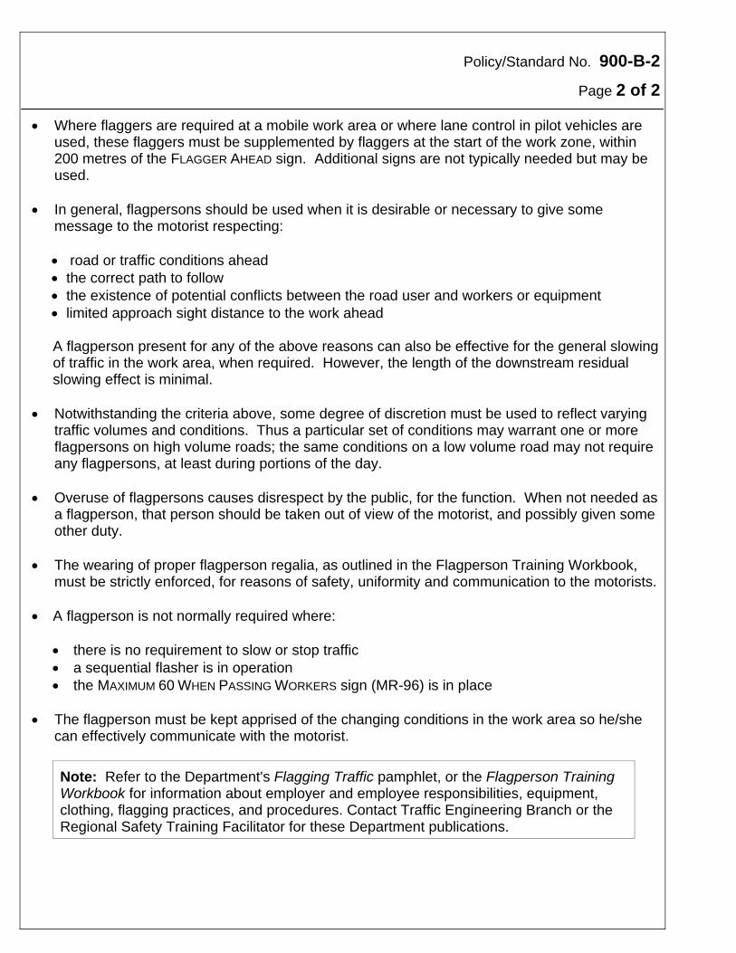
Policy/Standard No. 900-B-2
Page 2 of 2 Where flaggers are required at a mobile work area or where lane control in pilot vehicles are
used, these flaggers must be supplemented by flaggers at the start of the work zone, within 200 metres of the FLAGGER AHEAD sign. Additional signs are not typically needed but may be used.
In general, flagpersons should be used when it is desirable or necessary to give some
message to the motorist respecting: road or traffic conditions ahead the correct path to follow the existence of potential conflicts between the road user and workers or equipment limited approach sight distance to the work ahead
A flagperson present for any of the above reasons can also be effective for the general slowing of traffic in the work area, when required. However, the length of the downstream residual slowing effect is minimal.
Notwithstanding the criteria above, some degree of discretion must be used to reflect varying
traffic volumes and conditions. Thus a particular set of conditions may warrant one or more flagpersons on high volume roads; the same conditions on a low volume road may not require any flagpersons, at least during portions of the day.
Overuse of flagpersons causes disrespect by the public, for the function. When not needed as
a flagperson, that person should be taken out of view of the motorist, and possibly given some other duty.
The wearing of proper flagperson regalia, as outlined in the Flagperson Training Workbook,
must be strictly enforced, for reasons of safety, uniformity and communication to the motorists. A flagperson is not normally required where:
there is no requirement to slow or stop traffic a sequential flasher is in operation the MAXIMUM 60 WHEN PASSING WORKERS sign (MR-96) is in place
The flagperson must be kept apprised of the changing conditions in the work area so he/she
can effectively communicate with the motorist.
Note: Refer to the Department's Flagging Traffic pamphlet, or the Flagperson Training Workbook for information about employer and employee responsibilities, equipment, clothing, flagging practices, and procedures. Contact Traffic Engineering Branch or the Regional Safety Training Facilitator for these Department publications.
Policy/Standard No. 900-B-3
Effective Date: April 15, 1997
Traffic Control Device: Work Zone Date of Revision: March 15, 2002 Division: Subject: Signs Page 1 of 1 Purpose Traffic signs are used to inform and guide motorists through construction and maintenance work zones. They can convey both general and specific messages through the use of words or symbols.
Policy Only those signs approved for use in Manitoba may be installed in a construction and maintenance zone. Any existing or temporary signs that become redundant or contradictory because of work zone activities must be promptly removed.
Standard Application and use of traffic signs are governed by the Highway Traffic Act, and its supporting regulations, and by Manitoba Infrastructure and Transportation policies (including Traffic Engineering Branch Policies 100-A-1 to 100-H-3). Refer to these sources for specific applications on the use of these signs. In general only those signs listed and described herein may be used in work zones.
RECOMMENDED: “ORIGINAL SIGNED BY” APPROVED: “ORIGINAL SIGNED BY” Director, Traffic Engineering Executive Director Highway Engineering
Policy/Standard No. 900-B-4
Effective Date: April 15, 1997
Traffic Control Device: Work Zone Date of Revision: March 15, 2002 Division: Subject: Sign Placement Page 1 of 2 Purpose Sign placement is critical for motorist recognition and legibility. Sign placement standardization cannot always be attained in practice because signs, in all cases, must be placed in the most advantageous position.
Policy All traffic signs should be located in the most advantageous position for the motorist.
Standard Notwithstanding that sign positions are dependent on many extraneous factors the following guidelines should be used when installing signs in work zones: Temporary signs in construction and maintenance work zones should normally be positioned
on the right-hand side of the road. When two or more adjacent lanes accommodate traffic travelling in the same direction, and sufficient space is available on the median, signs must be positioned on both sides of the roadway.
Signs must be positioned within the cone of vision of the motorist in a location where they will
convey their message most effectively. On uncurbed roadways all signs, except those mounted on portable sign stands, must be
positioned clear of the highway shoulder line by at least 1.0 m. On curbed roadways signs must be positioned clear of the curb edge by a minimum of 600 mm
in rural areas and 400 mm in urban areas. All installations must be mounted so that the sign face is oriented towards oncoming traffic and
must be constructed to yield upon impact, minimizing the hazard to motorists. For long duration construction and maintenance work, signs should be mounted on minimum
100 x 100 mm wood posts. RECOMMENDED: “ORIGINAL SIGNED BY” APPROVED: “ORIGINAL SIGNED BY” Director, Traffic Engineering Executive Director Highway Engineering
Policy/Standard No. 900-B-4
Page 2 of 2 Signs mounted on portable sign stands should be a minimum 600 mm above the surface of the
road. Signs mounted on more permanent structures should be mounted at minimum 1.5 m above the
surface of the road.

Policy/Standard No. 900-B-5
Effective Date: April 15, 1997
Traffic Control Device: Work Zone Date of Revision: March 15, 2002 Division: Subject: Portable Signs Page 1 of 1 Purpose Signs mounted on approved portable sign stands are suitable for short term projects, maintenance operations or to advise of temporary roadway conditions.
Policy Portable signs must be installed prior to work commencing and should be moved and maintained as the work progresses. If a portable sign is used to identify a hazardous condition, the sign should remain in place until the hazard has been eliminated.
Standard Sign stands should be placed on the shoulder, clear of normal vehicular traffic. They should stand vertically facing motorists and must be pinned, ballasted or so designed that wind gusts will not topple the sign. Portable signs should be offset from the adjacent travelled lane as much as the available shoulder width allows. Portable signs should be erected to a minimum height of 600 mm above the surface of the adjacent travelled lane. For enhanced visibility, fluorescent blaze orange flags may be attached to the sign stand. The use of steel plates, tire rims and other non-approved devices as sign stand bases is strictly prohibited. When a ballast is needed to keep the sign stands in place, that ballast must consist of loose free flowing granular material contained in a soft, durable bag (sand bag). Rocks, bricks, or any other solid object, must never be used as these can present a hazard to motorists. The following sign stands are approved by Manitoba Infrastructure and Transportation: Flexmast Model PCC3648 Quadra Flex Model QFVR Windmaster Model 4818 Stellmaster Model 505M RECOMMENDED: “ORIGINAL SIGNED BY” APPROVED: “ORIGINAL SIGNED BY” Director, Traffic Engineering Executive Director Highway Engineering
Policy/Standard No. 900-B-6
Effective Date: April 15, 1997
Traffic Control Device: Work Zone Date of Revision: March 15, 2002 Division: Subject: Optional Sign Mounting Locations Page 1 of 1 Purpose Occasionally it is desirable to locate signs in other than typical locations.
Policy Subject to the approval of the Director of Traffic Engineering sign installations may be located in non-typical locations.
Standard For specific operations, certain signs may be effectively mounted on the rear of a vehicle stationed upstream of the work or moving along with the work. This may be the working vehicle itself, or a trailing/buffer vehicle provided expressly for this purpose. Signs should not normally be mounted on barricades. This does not include the CONSTRUCTION
ENDS sign (TC-1) which is mounted on gateway assemblies and notes the outer limits of a construction area. RECOMMENDED: “ORIGINAL SIGNED BY” APPROVED: “ORIGINAL SIGNED BY” Director, Traffic Engineering Executive Director Highway Engineering
Policy/Standard No. 900-B-7
Effective Date: April 15, 1997
Traffic Control Device: Work Zone Date of Revision: March 15, 2002 Division: Subject: Sign Spacing Page 1 of 1 Purpose The spacing of signs in construction and maintenance work zones must allow a motorist time to understand and respond to a given sign before coming upon the next. In work zones, sign spacing is largely dependent on the posted speed limit.
Policy On roadways with a posted speed of 80 km/h or less, signs should normally be spaced at least 100 m apart. On roads with speed limits greater than 80 km/h, and on all four-lane divided highways, the sign spacing should normally be at least 150 m. The sign spacing may be adjusted if required by sight distance limitations, work zone conditions, or space constraints. In any case, signs should not be spaced less than 50 m apart. RECOMMENDED: “ORIGINAL SIGNED BY” APPROVED: “ORIGINAL SIGNED BY” Director, Traffic Engineering Executive Director Highway Engineering
Policy/Standard No. 900-B-8
Effective Date: April 15, 1997
Traffic Control Device: Work Zone Date of Revision: March 15, 2002 Division: Subject: Passing Restrictions Page 1 of 1 Purpose Pavement markings are an integral part of any traffic control system. In some cases they are used to supplement the operation of other traffic control devices such as signs or signals. However, in many instances they stand alone and must obtain results solely on their own merits. This is the case with those pavement markings that advise motorists that sections of roadway have limited sight distance, and that passing is prohibited. As a consequence it is imperative that passing restrictions due to limited sight distance be maintained at all times. In construction and maintenance areas where pavement markings are obliterated, the only effective way of maintaining passing restrictions is through the use of appropriate signs.
Policy In construction and maintenance areas when pavement markings are obliterated, the beginning and end of all passing restrictions which mark locations of limited sight distance should be identified with signs. These signs should be installed prior to the start of any activity that obliterates the existing pavement markings. The beginning of passing restrictions should be identified by a PASSING PROHIBITED sign (RB-31), and the end of these passing restrictions identified by a PASSING PERMITTED sign (RB-32). When lengthy passing restrictions are obliterated, additional PASSING PROHIBITED signs should be used at minimum intervals of 1 km to provide ongoing positive warning of the continuing passing restrictions. PASSING PROHIBITED and PASSING PERMITTED signs should be removed once the pavement markings have been reinstalled.
RECOMMENDED: “ORIGINAL SIGNED BY” APPROVED: “ORIGINAL SIGNED BY” Director, Traffic Engineering Executive Director Highway Engineering
Policy/Standard No. 900-B-9
Effective Date: April 15, 1997
Traffic Control Device: Work Zone Date of Revision: September 29, 2008
Division: Subject: Barricades Page 1 of 3 Purpose A barricade is used to physically separate traffic from unusual situations created by construction and maintenance work activities or from objects on or near the travelled way.
Policy A barricade or system of barricades should be used where a collision with an object would be more hazardous than a collision with a barricade. If barricades are found to be more hazardous, traffic cones, plastic drums or other traffic control devices should be used instead. Barricades can also be used to block off a portion or all of a lane or roadway where road closures become a necessity. Barricades must not be used to channelize traffic.
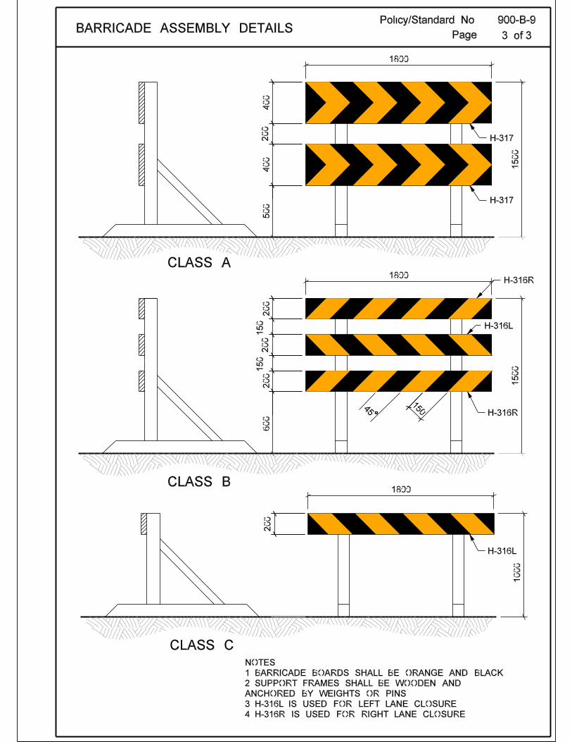
Standard A barricade may be one of three types: Class A, Class B, or Class C. Each class of barricade consists of one to three barricade boards or rails attached to a frame constructed of wood or other approved lightweight material: Class A barricade - Two 400 x 1800 mm barricade boards (H-317), spaced 200 mm apart, with a total height of 1500 mm. Class B barricade - Three 200 x 1800 mm rails (H-316R/L), spaced 150 mm apart, with a total height of 1500 mm. A H-316L board is installed at the top and bottom of the barricade, and a H-316R is mounted in the middle. Class C barricade - One 200 x 1800 mm barricade board (H-316R/L), with a height of 1000 mm. Markings for barricade boards must be alternate 150 mm wide orange and black diagonal stripes, reflectorized to a level meeting or exceeding the requirements for Type IV (micro-prismatic) sheeting as described in the ASTM standard D 4956. The predominate colour of other barricade components should be either orange or white. Owner identification must not be imprinted on the reflectorized face of any board or rail, but may be imprinted on the supports or the rear face of the boards.
RECOMMENDED: “ORIGINAL SIGNED BY” APPROVED: “ORIGINAL SIGNED BY” Director, Traffic Engineering Executive Director Highway Engineering
Policy/Standard No. 900-B-9
Page 2 of 3 Barricade Applications The three barricade classes are employed as follows: Class A barricades are used to effect a lane closure. They are placed at the end of a
transition taper and show the direction of the detour. Class B barricades are generally used to effect a complete roadway closure. Class C barricades may be placed at regular intervals within a work zone in order to
maintain a lane closure. Barricades may be used singly or in groups to mark hazards. They must be kept in good repair and cleaned or re-sheeted as necessary to maintain their appearance. A BARRICADE AHEAD sign (MC-4) should be installed to give motorists advance warning of a barricade.
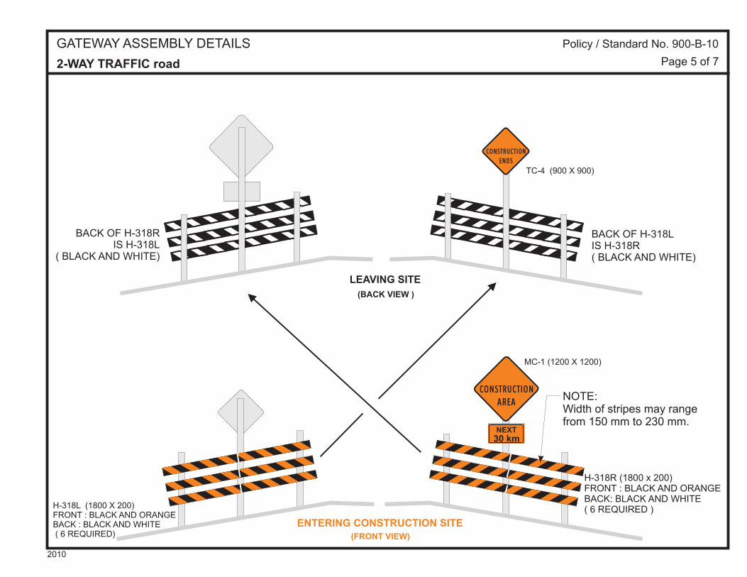
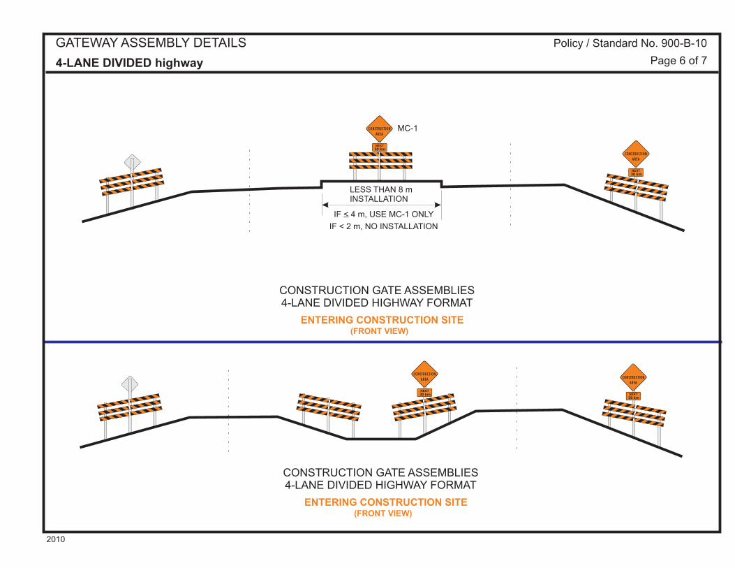
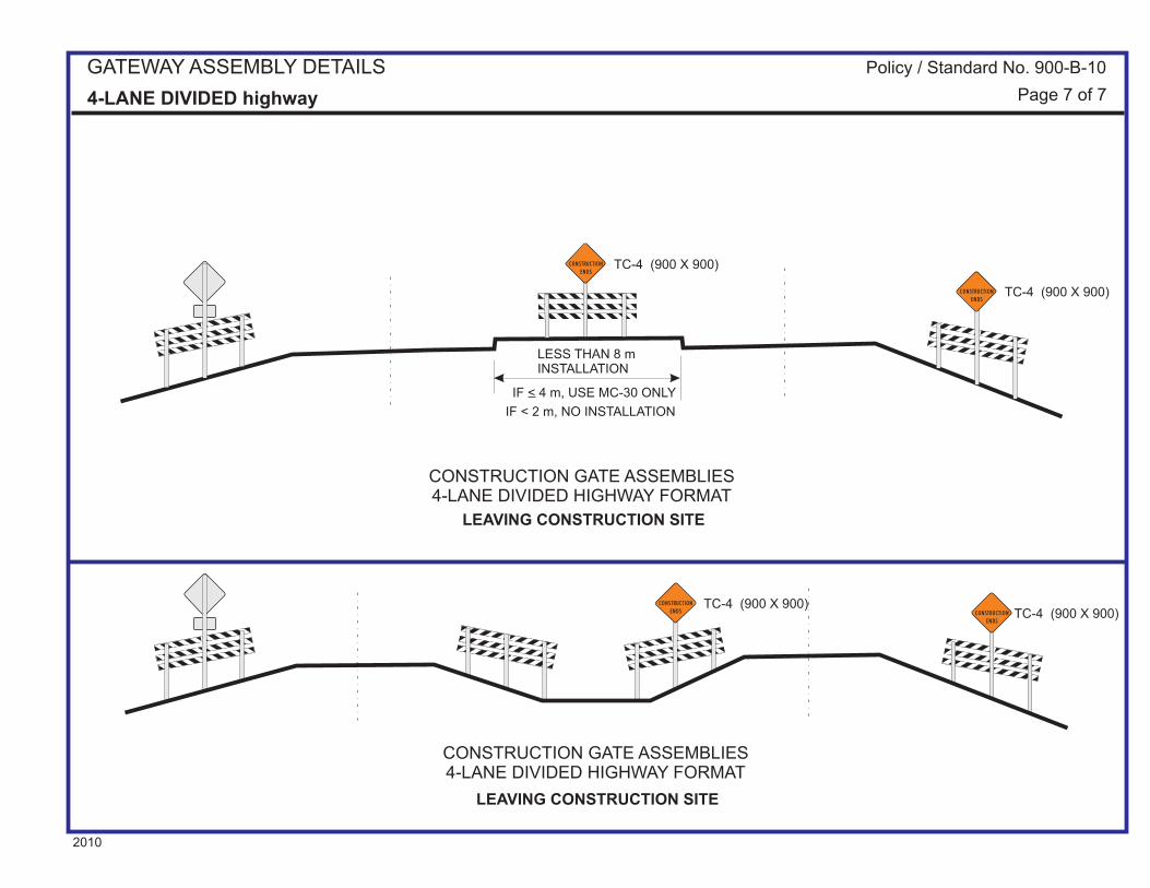
Policy/Standard No. 900-B-10
Effective Date: April 15, 1997
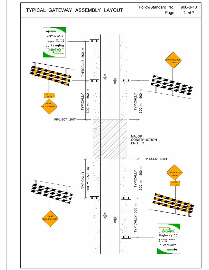
Traffic Control Device: Work Zone Date of Revision: February 10, 2009 Division: Subject: Gateway Assembly Page 1 of 7 Purpose Gateway assemblies are special barricades used to denote the outer limits of a construction area.
Policy Gateway assemblies must be installed at the limits of a long term construction project as indicated in the Traffic Management Plan (TMP) for that project.
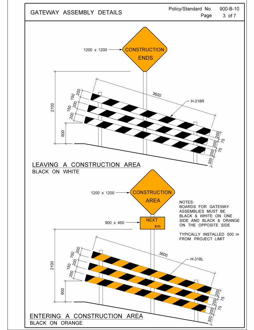
Standard Gateway assemblies consist of three 200 x 3600 mm double-sided barricade boards (H-318R/L), mounted as shown on page 2. Each board is reflectorized to a level meeting or exceeding the requirements for Type IV (micro-prismatic) sheeting as described in the ASTM standard D 4956 and has 150 mm wide orange and black diagonal stripes on one side and 150 mm wide white and black diagonal stripes on the other. The barricade boards (H-318R)are installed on gateway assemblies placed to the right of traffic and the barricade boards (H-318L) are installed on those placed to the left. Each gateway assembly is equipped with either a CONSTRUCTION AREA sign (MC-1), with a sign tab (WA-28S (orange)) if necessary, or a CONSTRUCTION ENDS sign (TC-4). A gateway assembly is installed at the break point of the shoulder on each side of the roadway. Gateways are oriented so that the CONSTRUCTION AREA sign and the orange and black side of the barricade boards (H-318R/L) are visible to oncoming traffic. Traffic leaving a construction area shall see a CONSTRUCTION ENDS sign and the white and black side of H-318R/L rails.
RECOMMENDED: “ORIGINAL SIGNED BY” APPROVED: “ORIGINAL SIGNED BY” Director, Traffic Engineering Executive Director Highway Engineering
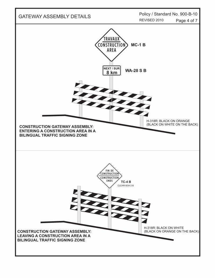
NEXT / SUR
8 km
CONSTRUCTION GATEWAY ASSEMBLY:ENTERING A CONSTRUCTION AREA IN ABILINGUAL TRAFFIC SIGNING ZONE
H-318R: BLACK ON ORANGE(BLACK ON WHITE ON THE BACK)
MC-1 B
WA-28 S B
CONSTRUCTIONTRAVAUX
AREA
GATEWAY ASSEMBLY DETAILSPolicy / Standard No. 900-B-10
Page 4 of 7REVISED 2010
CONSTRUCTION GATEWAY ASSEMBLY:LEAVING A CONSTRUCTION AREA IN ABILINGUAL TRAFFIC SIGNING ZONE
H-318R: BLACK ON WHITE(BLACK ON ORANGE ON THE BACK)
TC-4 B
CONSTRUCTIONENDS
FIN DECONSTRUCTION
CLEARVIEW-2-B
NEXT30 km
H-318R (1800 x 200)FRONT : BLACK AND ORANGEBACK: BLACK AND WHITE( 6 REQUIRED ) H-318L (1800 X 200)
FRONT : BLACK AND ORANGEBACK : BLACK AND WHITE ( 6 REQUIRED)
BACK OF H-318RIS H-318L
( BLACK AND WHITE)
BACK OF H-318LIS H-318R( BLACK AND WHITE)
ENTERING CONSTRUCTION SITE(FRONT VIEW)
LEAVING SITE
(BACK VIEW )
2-WAY TRAFFIC road
NOTE:Width of stripes may rangefrom 150 mm to 230 mm.
CONSTRUCTION
AREA
MC-1 (1200 X 1200)
TC-4 (900 X 900)
GATEWAY ASSEMBLY DETAILS Policy / Standard No. 900-B-10
Page 5 of 7
CONSTRUCTION
ENDS
2010
NEXT
NEXT
NEXTNEXT
30 km
30 km
30 km30 km
ENTERING CONSTRUCTION SITE
ENTERING CONSTRUCTION SITE
(FRONT VIEW)
(FRONT VIEW)
CONSTRUCTION GATE ASSEMBLIES4-LANE DIVIDED HIGHWAY FORMAT
CONSTRUCTION GATE ASSEMBLIES4-LANE DIVIDED HIGHWAY FORMAT
LESS THAN 8 mINSTALLATION
CONSTRUCTION
CONSTRUCTION
CONSTRUCTIONCONSTRUCTION
AREA
AREA
AREAAREA
IF < 4 m, USE MC-1 ONLY
IF < 2 m, NO INSTALLATION
MC-1
4-LANE DIVIDED highway
GATEWAY ASSEMBLY DETAILS Policy / Standard No. 900-B-10
Page 6 of 7
2010
CONSTRUCTION
AREA
CONSTRUCTION
AREA
NEXT
NEXT
30 km
30 km
LEAVING CONSTRUCTION SITE
LEAVING CONSTRUCTION SITE
CONSTRUCTION GATE ASSEMBLIES4-LANE DIVIDED HIGHWAY FORMAT
CONSTRUCTION GATE ASSEMBLIES4-LANE DIVIDED HIGHWAY FORMAT
LESS THAN 8 mINSTALLATION
IF < 4 m, USE MC-30 ONLY
IF < 2 m, NO INSTALLATION
4-LANE DIVIDED highway
GATEWAY ASSEMBLY DETAILS Policy / Standard No. 900-B-10
Page 7 of 7
TC-4 (900 X 900)
TC-4 (900 X 900)TC-4 (900 X 900)
TC-4 (900 X 900)
CONSTRUCTION
CONSTRUCTION
CONSTRUCTION
CONSTRUCTION
ENDS
ENDS
ENDS
ENDS
2010
Policy/Standard No. 900-B-11
Effective Date: April 15, 1997
Traffic Control Device: Work Zone Date of Revision: March 15, 2002 Division: Subject: Hazard Markers Page 1 of 3 Purpose Delineation, channelization, and hazard markers warn and alert motorists to hazards associated with construction and maintenance work areas.
Policy Objects within and adjacent to the roadway which constitute a hazard to traffic require uniform delineation to ensure motorists have sufficient warning to recognise the danger and make a proper response. Area hazards that require delineation include: bridge ends excavation areas Longitudinal hazards that require delineation include: gravel windrows bench cuts pavement edge drop-offs
Standard Area hazards Bridge ends and excavation areas must be delineated using either poly posts, drums (900-B-12), or construction markers (H-315T) to ensure motorists have sufficient warning to recognise the hazard and take appropriate action. RECOMMENDED: “ORIGINAL SIGNED BY” APPROVED: “ORIGINAL SIGNED BY” Director, Traffic Engineering Executive Director Highway Engineering
Policy/Standard No. 900-B-11
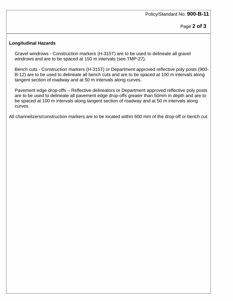
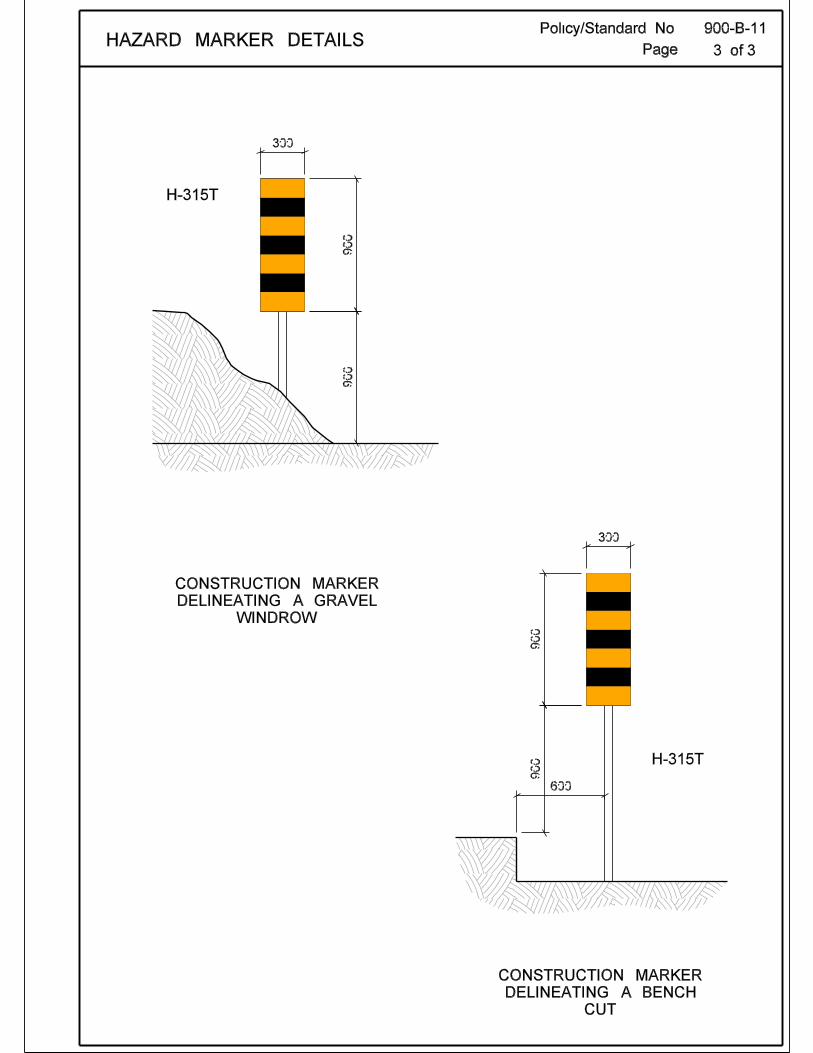
Page 2 of 3 Longitudinal Hazards
Gravel windrows - Construction markers (H-315T) are to be used to delineate all gravel windrows and are to be spaced at 150 m intervals (see TMP-27).
Bench cuts - Construction markers (H-315T) or Department approved reflective poly posts (900-B-12) are to be used to delineate all bench cuts and are to be spaced at 100 m intervals along tangent section of roadway and at 50 m intervals along curves. Pavement edge drop-offs – Reflective delineators or Department approved reflective poly posts are to be used to delineate all pavement edge drop-offs greater than 50mm in depth and are to be spaced at 100 m intervals along tangent section of roadway and at 50 m intervals along curves.
All channelizers/construction markers are to be located within 600 mm of the drop-off or bench cut.
Policy/Standard No. 900-B-12
Effective Date: April 15, 1997
Traffic Control Device: Work Zone Date of Revision: May 23, 2007 Division: Subject: Channelizers and Delineators Page 1 of 3 Purpose There are several devices available which aid in the guidance of motorists through or around a hazardous area, or work zone.
Policy All devices intended for delineation and channelization purposes must be approved by the Manitoba Infrastructure and Transportation. They must be designed to yield if struck by an errant vehicle, and must conform with the specifications described herein in terms of size, shape, colour, and reflectivity. Unless otherwise directed, only those delineators and channelizers specified in a Traffic Management Plan (TMP) may be installed in a construction and maintenance work zone. Traffic cones are intended for daytime operations only and must not be used if the traffic control must be left in place overnight.
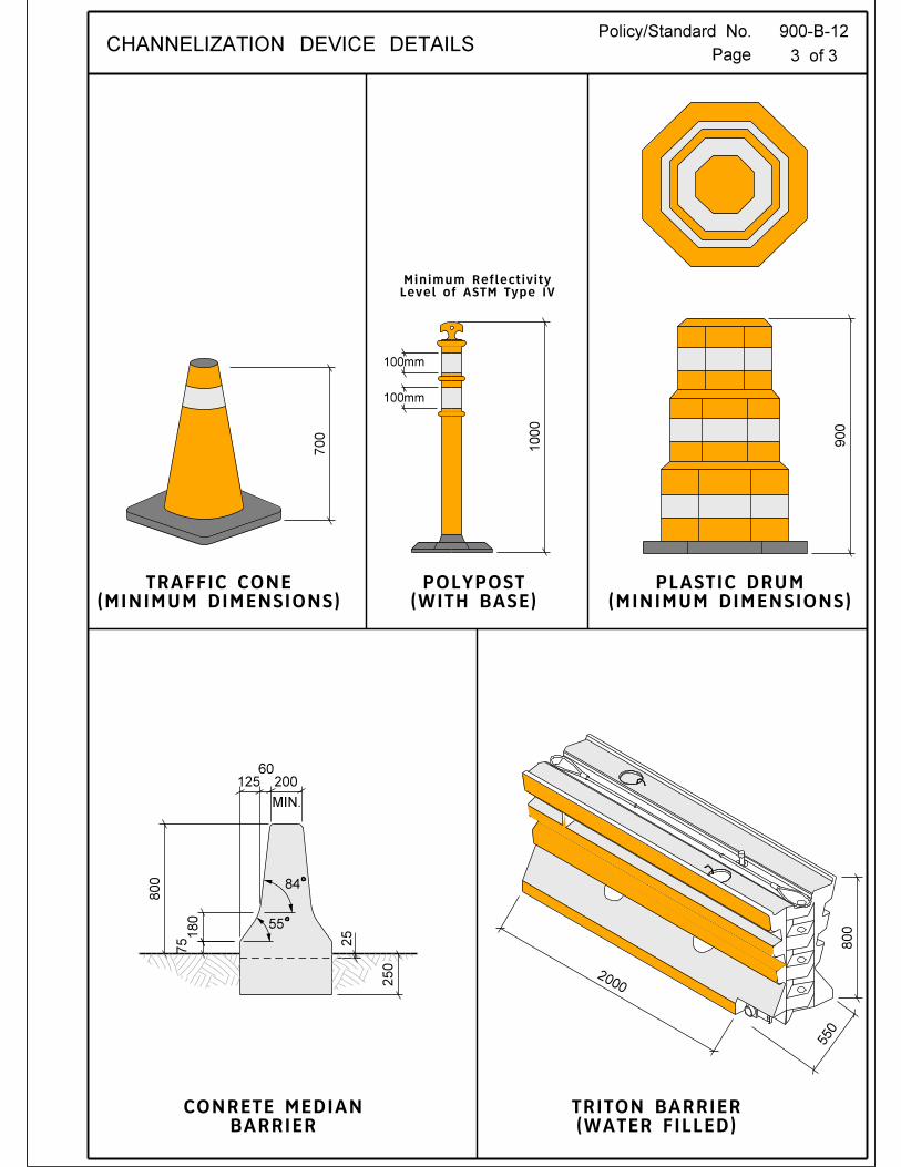
Standard The following devices are generally approved for delineation or channelization. It is preferable to use plastic drums for lead in tapers. Plastic Posts ("Polyposts") Size: 50 mm diameter x 1000 mm, nominal Shape: Tubular Colour: Orange post with 200 mm wide white reflective sheeting, nominal Reflectivity: High Intensity (ASTM – Type III) Plastic posts ("polyposts") are available in a variety of sizes and can be used as both delineators and channelizers. They can be implanted in the ground or fitted with bases that can be affixed to the pavement. Polyposts yield when struck by vehicles, are self-recovering and can usually withstand numerous impacts. Only approved polyposts may be used in construction and maintenance work zones. RECOMMENDED: “ORIGINAL SIGNED BY” APPROVED: “ORIGINAL SIGNED BY” Director, Traffic Engineering Executive Director Highway Engineering
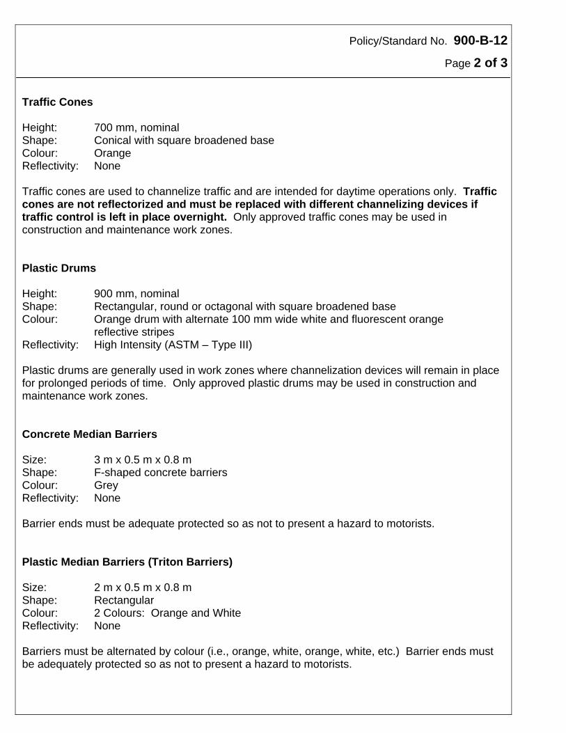
Policy/Standard No. 900-B-12
Page 2 of 3 Traffic Cones Height: 700 mm, nominal Shape: Conical with square broadened base Colour: Orange Reflectivity: None Traffic cones are used to channelize traffic and are intended for daytime operations only. Traffic cones are not reflectorized and must be replaced with different channelizing devices if traffic control is left in place overnight. Only approved traffic cones may be used in construction and maintenance work zones. Plastic Drums Height: 900 mm, nominal Shape: Rectangular, round or octagonal with square broadened base Colour: Orange drum with alternate 100 mm wide white and fluorescent orange
reflective stripes Reflectivity: High Intensity (ASTM – Type III) Plastic drums are generally used in work zones where channelization devices will remain in place for prolonged periods of time. Only approved plastic drums may be used in construction and maintenance work zones. Concrete Median Barriers Size: 3 m x 0.5 m x 0.8 m Shape: F-shaped concrete barriers Colour: Grey Reflectivity: None Barrier ends must be adequate protected so as not to present a hazard to motorists. Plastic Median Barriers (Triton Barriers) Size: 2 m x 0.5 m x 0.8 m Shape: Rectangular Colour: 2 Colours: Orange and White Reflectivity: None Barriers must be alternated by colour (i.e., orange, white, orange, white, etc.) Barrier ends must be adequately protected so as not to present a hazard to motorists.
Policy/Standard No. 900-B-13
Effective Date: April 15, 1997
Traffic Control Device: Work Zone Date of Revision: January 13, 2006 Division: Subject: Sign Reflectivity Page 1 of 1 Purpose Retroreflectivity greatly increases the conspicuity of traffic control devices, particularly in low light and reduced visibility conditions.
Policy Further to Section A1.6.7 of the TAC MUTCD, all signs and other devices used in construction and maintenance work zones must be reflectorized with a material that has a smooth, sealed outer surface which shows the device in approximately the same shape and colour both day and night.
Standard The retroreflective sheeting material must be at a minimum high intensity grade ASTM D4556 Type III (or approved equivalent), specified. In situations where extra visibility is required, diamond grade retroreflective sheeting may be used, subject to Manitoba Infrastructure and Transportation approval. Non-reflective fluorescent sheeting material must not be used. The retroreflective surfaces must be cleaned or replaced as often as necessary to provide full retroreflectivity. RECOMMENDED: “ORIGINAL SIGNED BY” APPROVED: “ORIGINAL SIGNED BY” Director, Traffic Engineering Executive Director Highway Engineering
Policy/Standard No. 900-B-14
Effective Date: April 15, 1997
Traffic Control Device: Work Zone Date of Revision: March 15, 2002 Division: Subject: Maintenance Page 1 of 1 Purpose Proper maintenance is essential for the desired performance of traffic control devices.
Policy All signs and other traffic control devices must be monitored to ensure proper location, legibility and condition. If necessary, inadequate devices must be immediately repositioned, repaired or replaced.
Standard Reflective surfaces must be kept clean at all times and should be checked at the end of each day. Nighttime inspections must be performed periodically to ensure reflective levels are adequate. Signs with inadequate reflective levels must be discarded and replaced. If the traffic control is left in place overnight, only those signs necessary to protect motorists must remain in place. Non-applicable signs must be removed or covered. RECOMMENDED: “ORIGINAL SIGNED BY” APPROVED: “ORIGINAL SIGNED BY” Director, Traffic Engineering Executive Director Highway Engineering
Policy/Standard No. 900-B-15
Effective Date: April 15, 1997
Traffic Control Device: Work Zone Date of Revision: March 15, 2002 Division: Subject: Enhancement Page 1 of 1 Purpose Under some circumstances traffic control devices should be enhanced to better draw the attention of motorists. This can be accomplished through several approved methods.
Policy When conditions dictate, traffic control devices used in a Traffic Management Plan (TMP) may be enhanced to increase the conspicuity of the devices. Care must be taken not to overdo this process as motorist expectation may be effected. All enhancements require approval of Traffic Engineering Branch.
Standard The following methods may be used, subject to approval, for the enhancement of traffic control devices: Oversizing - Increasing the size of temporary condition signs enhances visibility. However, care
must be taken not to throw a group of signs out of balance by installing one that is disproportionately large.
Flags - Fluorescent orange flags can be attached to temporary condition signs. Sequential Flashing Arrow Boards - Flasher units are recommended to better indicate a closed
lane or merge direction. However, since flashers are susceptible to mechanical or electrical failure they must not be used as a primary device. The work zone must be fully controlled with or without the presence of a sequential flasher unit.
Reposition Devices - Traffic control devices may be relocated laterally or longitudinally to
increase their visibility or to enhance the "total effect" as long as they remain within a motorist's cone of vision.
Illumination - External illumination may be used to increase nighttime visibility. Reduce "Clutter" - Existing signs or other traffic control devices that are not necessary to protect
motorists should be removed. RECOMMENDED: “ORIGINAL SIGNED BY” APPROVED: “ORIGINAL SIGNED BY” Director, Traffic Engineering Executive Director Highway Engineering
Policy/Standard No. 900-B-16
Effective Date:
Traffic Control Device: Work Zone Date of Revision: February 2005 Division: Temporary Warning Subject: Protection from Vehicular Traffic – Enhanced Visibility Page 1 of 1 Purpose For safety reasons, all workers exposed to vehicular traffic on a project site must be visible to motorists. (See Policy 900-A-4 “Worker Visibility on Roadway”) This includes anyone walking on or adjacent to any roadway that is open to vehicular traffic.
Policy All workers, whether directly employed by the Manitoba Infrastructure and Transportation or by a contractor doing work on behalf of Manitoba Infrastructure and Transportation, exposed to the hazard of vehicular traffic on a project site on a street, highway, or other roadway, shall wear high-visibility safety apparel that complies with the requirements of CSA Standard Z96-02 High-Visibility Safety Apparel.
RECOMMENDED: “ORIGINAL SIGNED BY” APPROVED: “ORIGINAL SIGNED BY” Director, Traffic Engineering Executive Director Highway Engineering
Policy/Standard No. 900-B-17
Effective Date:
Traffic Control Device: Work Zone Date of Revision: March 15, 2002 Division: Temporary Warning Subject: Traffic Control – Stringline Installation Page 1 of 1 Purpose During paving operations, the worker installing the stringline in front of the paver requires protection as he/she is continually exposed to the hazard of vehicular traffic.
Policy A worker installing a stringline on a roadway open to vehicular traffic must be accompanied by at least one flagperson.
Standard The flagperson should, at all times, be within 10 metres of the stringline person. RECOMMENDED: “ORIGINAL SIGNED BY” APPROVED: “ORIGINAL SIGNED BY” Director, Traffic Engineering Executive Director Highway Engineering
Policy/Standard No. 900-B-18
Effective Date: March 15, 2002
Traffic Control Device: Work Zone Division: Temporary Warning Subject: Traffic Control-Temporary Overlay Markers (TOMs) Page 1 of 1 Purpose Workers installing temporary overlay markers (TOM’s) require protection as they are continually exposed to the hazard of vehicular traffic.
Policy A worker installing temporary overlay markers (TOM’s) on a roadway open to vehicular traffic must be accompanied by at least one flagperson, unless the activity is already being controlled by existing flagpeople.
Standard The flagperson should, at all times, be within 10 metres of the person installing the TOM’s. RECOMMENDED: “ORIGINAL SIGNED BY” APPROVED: “ORIGINAL SIGNED BY” Director, Traffic Engineering Executive Director Highway Engineering
Policy/Standard No. 900-B-19
Effective Date: July 24, 2000
Traffic Control Device: Work Zone Date of Revision: April 14, 2010 Division: Subject: Working Near Railway Crossings Page 1 of 2 Purpose Working near highway-railway grade crossings presents a special set of traffic control problems. Protection of the travelling public, security of railway operations, and the safety of workers is paramount. Policy Whenever a road construction or maintenance activity is carried out within 100 meters of an at-grade railway crossing, the appropriate railway must be contacted regarding the operation of the trains to ensure the safety of the grade crossing during such work. No work on the highway within the railway right-of-way may take place without specific approval of the railway (except for routine “through” operations such as highway snow clearing operations, road marking, etc.). Standard
Notification should be given to the railway whenever possible, at least 72 hours prior to commencement of work, advising of the crossing location, and the nature and duration of the work. Required temporary traffic control devices must be carefully placed so they do not detract from the visibility or impact of Railway Crossing signs (Crossbucks), Advance Railway Crossing signs, or Automatic Crossing Protection, if installed. When Automatic Crossing Protection is in place, railway signals must never be operated manually by the rail authority to warn motorists that there is construction or maintenance taking place. Signals should only operate when a train causes them to operate, or during maintenance or construction of the signals themselves. Parked equipment and vehicles should not be within 30 m of railway tracks and must not be parked as to obstruct the sightlines of warning signals or other traffic control devices. When possible, the railway will put a “block” on the tracks in the area where roadwork is taking place. The “block” stops all trains from using the affected section of the tracks for the time allotted. RECOMMENDED: “ORIGINAL SIGNED BY” APPROVED: “ORIGINAL SIGNED BY” Director, Traffic Engineering Executive Director Highway Engineering
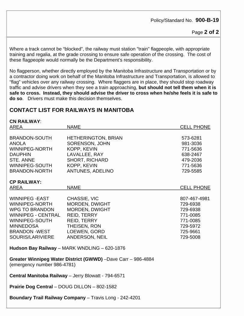
Policy/Standard No. 900-B-19
Page 2 of 2
Where a track cannot be “blocked”, the railway must station "train" flagpeople, with appropriate training and regalia, at the grade crossing to ensure safe operation of the crossing. The cost of these flagpeople would normally be the Department’s responsibility. No flagperson, whether directly employed by the Manitoba Infrastructure and Transportation or by a contractor doing work on behalf of the Manitoba Infrastructure and Transportation, is allowed to “flag” vehicles over any railway crossing. Where flaggers are in place, they should stop roadway traffic and advise drivers when they see a train approaching, but should not tell them when it is safe to cross. Instead, they should advise the driver to cross when he/she feels it is safe to do so. Drivers must make this decision themselves. CONTACT LIST FOR RAILWAYS IN MANITOBA CN RAILWAY: AREA NAME CELL PHONE BRANDON-SOUTH HETHERINGTON, BRIAN 573-6281 ANOLA SORENSON, JOHN 981-3036 WINNIPEG-NORTH KOPP, KEVIN 771-5636 DAUPHIN LAVALLEE, RAY 638-2467 STE. ANNE SHORT, RICHARD 479-2036 WINNIPEG-SOUTH KOPP, KEVIN 771-5636 BRANDON-NORTH ANTUNES, ADELINO 729-5585 CP RAILWAY: AREA NAME CELL PHONE WINNIPEG -EAST CHASSIE, VIC 807-467-4981 WINNIPEG-NORTH MORDEN, DWIGHT 729-6938 WPG TO BRANDON MORDEN, DWIGHT 729-6938 WINNIPEG - CENTRAL REID, TERRY 771-0085 WINNIPEG-SOUTH REID, TERRY 771-0085 MINNEDOSA THEISEN, RON 729-5972 BRANDON -WEST LOEWEN, GORD 725-9661 SOURIS/LARIVIERE ANDERSON, NEIL 729-5008 Hudson Bay Railway – MARK WNDLING – 620-1876 Greater Winnipeg Water District (GWWD) –Dave Carr – 986-4884 (emergency number 986-4781) Central Manitoba Railway – Jerry Blowatt - 794-6571 Prairie Dog Central – DOUG DILLON – 802-1582 Boundary Trail Railway Company – Travis Long - 242-4201
Policy/Standard No. 900-B-20
Effective Date: February 20, 2002
Traffic Control Device: Work Zone Date of Revision: March 15, 2002 Division: Temporary Warning Subject: Traffic Control – Paving Operation Page 1 of 1 Purpose During paving operations, workers on and alongside the paver require protection as they are continually exposed to the hazard of vehicular traffic.
Policy One flagperson (see Policy 900-B-2 “Flagpersons”) must accompany the self-propelled mechanical paver whenever the paver is operating on a roadway open to vehicular traffic.
Standard The flagperson should, at all times, be within 10 metres of the paver. RECOMMENDED: “ORIGINAL SIGNED BY” APPROVED: “ORIGINAL SIGNED BY” Director, Traffic Engineering Executive Director Highway Engineering
Policy/Standard No. 900-B-21
Effective Date: March 15, 2002
Traffic Control Device: Work Zone Division: Subject: Temporary Storage of Poles, Culverts, etc. in Right-of-Way Page 1 of 2 Purpose Delineation of rigid construction materials, such as culverts and utility poles, temporarily stored in Department right-of-way is required to alert operators of off-road vehicles and motorists of the potential hazard.
Policy It is occasionally necessary to temporarily store rigid construction materials, such as culverts and utility poles, in Department right-of-way before installation proceeds. These objects should be stored as far from the roadway travel lane as practical, with the following requirements: Rigid materials should be stored in the right-of-way for as short a period as practical. Rigid materials must not be stored within 4 meters of the travel lane. Where rigid materials are temporarily stored within the roadway “Clear Zone” (12 metres
from the edge of the travel lane), the area must be signed and delineated as a work zone. This would normally consist of a “construction area” sign with poly-posts or cones.
Where rigid materials are temporarily stored outside the “Clear Zone” but within Department right-of-way, they must be delineated.
Standard Poly-posts or cones with retroreflective sheeting should be used to delineate all rigid materials temporarily stored in Department right-of-way. Where poly-posts or cones are unavailable or impractical to use, a 75 mm x 75 mm (3 inch x 3 inch) fluorescent orange prismatic reflective material should be installed, at a minimum height of 600 mm (2 feet) above the ground surface. RECOMMENDED: “ORIGINAL SIGNED BY” APPROVED: “ORIGINAL SIGNED BY” Director, Traffic Engineering Executive Director Highway Engineering
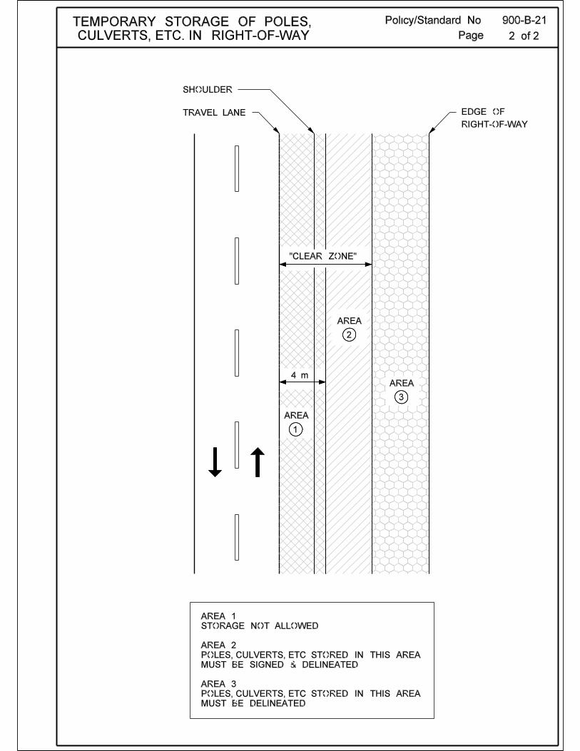
Policy/Standard No. 900-C-1
Effective Date: April 15, 1997
Traffic Control Device: Work Zone Date of Revision: March 15, 2002 Division: Subject: Traffic Management Plans Page 1 of 1 Purpose Traffic management and work activities must be coordinated in work zones to provide safe and expeditious movements of traffic while maintaining efficient work progress. Traffic controls in work zones warn of potential hazards, separate motorists from the work force and delineate a path for traffic to follow. Work zone traffic control devices are not normally used singly, but are applied as a system of devices. The development of a Traffic Management Plans (TMP) and the correct deployment of traffic control devices are key elements in achieving safe conditions within construction and maintenance work zones.
Policy A TMP, in sufficient detail to reflect the complexity of the construction and maintenance work and traffic conditions, must be prepared and put into operation before the site is occupied.
Standard A series of typical TMP have been developed to aid in the implementation of traffic management within work zones. These typicals are minimum standards which can be enhanced to deal with local conditions. Refer to TMP drawings. RECOMMENDED: “ORIGINAL SIGNED BY” APPROVED: “ORIGINAL SIGNED BY” Director, Traffic Engineering Executive Director Highway Engineering
Policy/Standard No. 900-C-2
Effective Date: April 15, 1997
Traffic Control Device: Work Zone Date of Revision: March 15, 2002 Division: Subject: Traffic Control Coordinator Page 1 of 1 Purpose The implementation of a Traffic Management Plan (TMP) requires dedicated staff trained in the appropriate principles and guidelines of the Traffic Management Plan.
Policy One person on each traffic control project, hereafter designated as the "traffic control coordinator", must have overall responsibility for implementing the TMP and ensuring that the plan is functioning properly.
Standard The duties and responsibilities of the traffic control coordinator include, but are not limited to: ensuring that only those traffic control devices approved by the Manitoba Infrastructure and
Transportation and called for by the TMP are used in a work zone ensuring that the guidelines of the Policies/Standards are met installing, positioning, relocating or removing traffic control devices as conditions change maintaining traffic control devices and ensuring their reflective surfaces are clean training flagpersons organizing and supervising the development and relief of flagpersons ensuring that flagpersons are properly informed concerning road conditions and that they are
relaying the proper information Since traffic control coordinators' actions affect construction and maintenance work zone safety every traffic control coordinator should receive training appropriate to their position. Only those who are qualified by means of adequate training in safe traffic management practices, and have a basic understanding of the principles established by the applicable Policies/Standards may be appointed to supervise the selection, placement, and maintenance of traffic control devices and train flagpersons. Completion of a Manitoba Infrastructure and Transportation sanctioned training course is highly recommended for all traffic control coordinators. RECOMMENDED: “ORIGINAL SIGNED BY” APPROVED: “ORIGINAL SIGNED BY” Director, Traffic Engineering Executive Director Highway Engineering
Policy/Standard No. 900-C-3
Effective Date: April 15, 1997
Traffic Control Device: Work Zone Date of Revision: March 15, 2002 Division: Subject: Work Zone Components Page 1 of 2 Purpose A work zone consists of the section of the roadway between the first advance warning sign and the point beyond the activity area where traffic is no longer affected. Most work zones can be divided into five areas as described below.
Policy All work zone Traffic Management Plans (TMP) will be designed to include the five areas of a work zone traffic control zone.
Advance Warning Area Transition Area Buffer Space Activity Area Termination Area
Standard Advance Warning Area An advance warning area is required for all work zones to alert motorists to the road work ahead. Motorists need enough time and distance to adjust to the altered conditions prior to reaching them. The warning area may vary from a single traffic control device, such as a ROAD
WORK sign (TC-2), to a series of traffic control devices. Transition Area When redirection of the driver’s normal path is required, traffic must be channelized from the normal path to a new path. This redirection is intended to occur at the beginning of the transition area. In mobile operations, this transition area moves with the work space. Transition areas usually involve strategic use of tapers, which (because of their importance) are described in Policy/Standard 900-C-4. RECOMMENDED: “ORIGINAL SIGNED BY” APPROVED: “ORIGINAL SIGNED BY” Director, Traffic Engineering Executive Director Highway Engineering
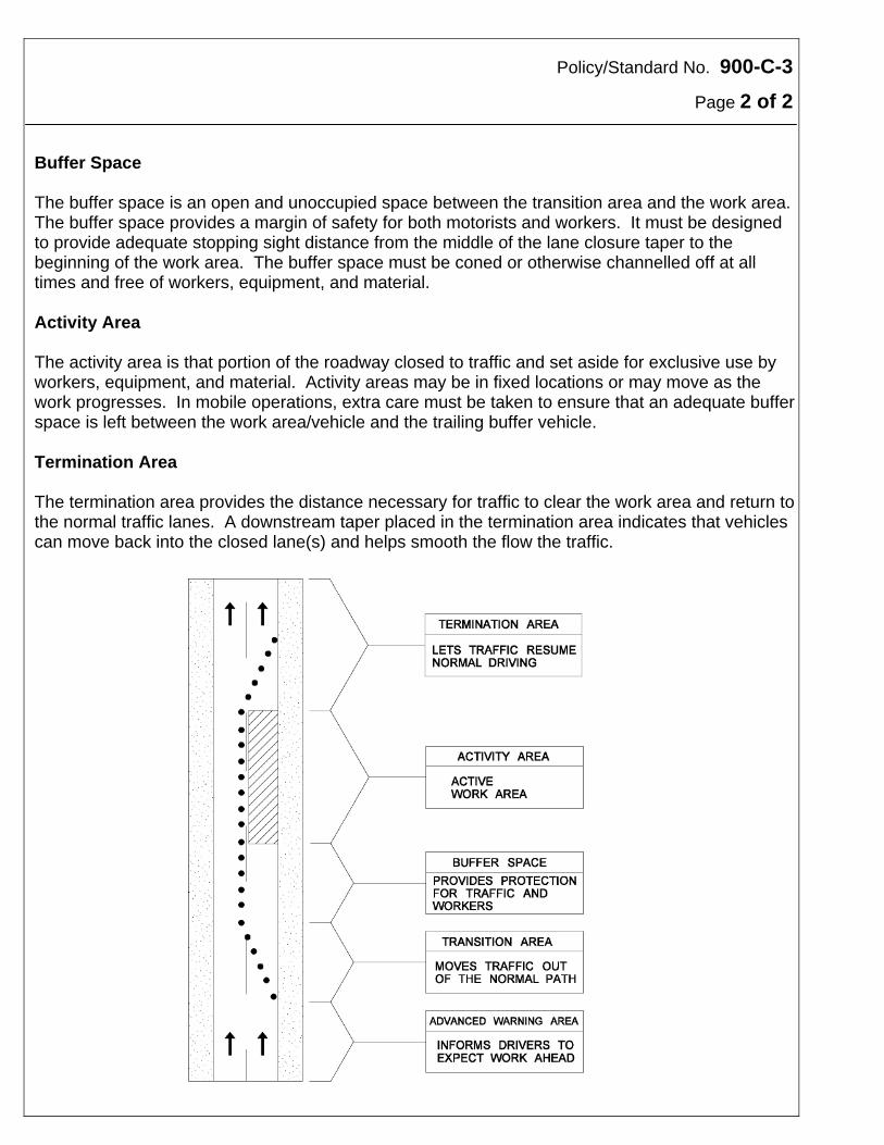
Policy/Standard No. 900-C-3
Page 2 of 2 Buffer Space The buffer space is an open and unoccupied space between the transition area and the work area. The buffer space provides a margin of safety for both motorists and workers. It must be designed to provide adequate stopping sight distance from the middle of the lane closure taper to the beginning of the work area. The buffer space must be coned or otherwise channelled off at all times and free of workers, equipment, and material. Activity Area The activity area is that portion of the roadway closed to traffic and set aside for exclusive use by workers, equipment, and material. Activity areas may be in fixed locations or may move as the work progresses. In mobile operations, extra care must be taken to ensure that an adequate buffer space is left between the work area/vehicle and the trailing buffer vehicle. Termination Area The termination area provides the distance necessary for traffic to clear the work area and return to the normal traffic lanes. A downstream taper placed in the termination area indicates that vehicles can move back into the closed lane(s) and helps smooth the flow the traffic.
Policy/Standard No. 900-C-4
Effective Date: April 15 1997
Traffic Control Device: Work Zones Date of Revision: March 15, 2002 Division: Subject: Transition Tapers Page 1 of 2 Purpose Transition tapers are used to channel/direct traffic around an activity area within a work zone. The length of the taper and the channelizer spacing is extremely important. Inadequate tapers result in undesirable traffic movements and increase the potential for accidents.
Policy Whenever traffic must be moved from the normal path of travel due to the presence of an activity area, a proper transition taper must be installed. The transition area must be obvious to motorists, and must be delineated with channelizing devices so motorists do not mistakenly follow the wrong path. For long duration projects, existing pavement markings must be removed where they conflict with transition delineation. Additional pavement markings may need to be installed to guide motorists. Standard There are four common transition tapers as described below. The included table provides normal taper lengths for the taper types and posted speed limits. Merging Taper - Merging tapers, used on multi-lane divided roadways to channel traffic from a
closed lane into an adjacent lane, require the greatest length. A merge lane must allow a motorist to locate and move into a gap in the adjacent traffic stream.
Shifting Taper - When a merge is not required, a shifting taper is used to channel vehicles
onto a different travel path. This taper is often used when traffic is routed around a work area by shifting it onto the shoulder or median. Changes in the travel path may also be accomplished with horizontal curves designed for normal highway speeds.
One-Lane Traffic Taper - A one-lane traffic taper is used in advance of work areas that
require a portion of the road be used alternately by traffic in both directions. Traffic is typically controlled by flagpersons and since no merging is taking place, the taper used to direct vehicles onto the one-way road section can be quite short.
RECOMMENDED: “ORIGINAL SIGNED BY” APPROVED: “ORIGINAL SIGNED BY” Director, Traffic Engineering Executive Director Highway Engineering
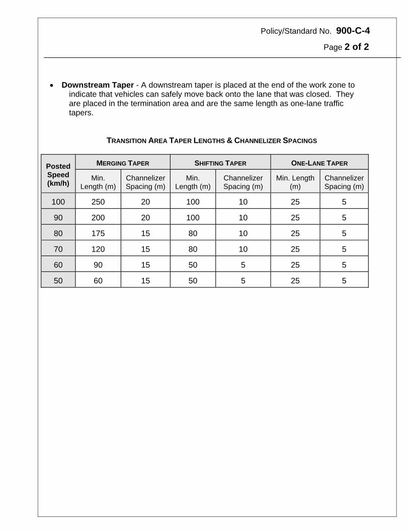
Policy/Standard No. 900-C-4
Page 2 of 2
Downstream Taper - A downstream taper is placed at the end of the work zone to
indicate that vehicles can safely move back onto the lane that was closed. They are placed in the termination area and are the same length as one-lane traffic tapers.
TRANSITION AREA TAPER LENGTHS & CHANNELIZER SPACINGS
Posted Speed (km/h)
MERGING TAPER SHIFTING TAPER
ONE-LANE TAPER
Min. Length (m)
Channelizer Spacing (m)
Min. Length (m)
Channelizer Spacing (m)
Min. Length
(m) Channelizer Spacing (m)
100
250
20 100 10 25
5
90
200
20 100 10 25
5
80
175
15 80 10 25
5
70
120
15 80 10 25
5
60
90
15 50 5 25
5
50
60
15 50 5 25
5
Policy/Standard No. 900-C-5
Effective Date: April 15, 1997
Traffic Control Device: Work Zone Date of Revision: March 15, 2002 Division: Subject: Installation and Removal of Traffic Control Devices Page 1 of 2 Purpose The installation and removal of temporary traffic control zones creates a situation which is often far more hazardous than the operation of the completed zone. The workers placing these advance warning devices and channelizing devices must be on the roadway at these points of high conflict. Furthermore, the placement operation constitutes a more unexpected situation for the motorist than does the work zone itself. To minimize these hazards, it is essential that the installation proceed in an orderly fashion and be accomplished as quickly as possible.
Policy Installation and removal of traffic control devices must be done in a manner which causes the least risk to traffic and which provides for the safety of workers installing or removing devices.
Standard Installation Sequence Devices are installed in the direction that traffic moves - this is, "downstream". The first device placed is the first advance warning sign, typically ROAD WORKS (TC-2). The installation then proceed with the:
Advance Warning area Transition area Buffer area Activity area Termination area
Installation Procedure The traffic control crew must disembark from their vehicles in a safe manner. All personnel must be attired properly to work on the roadway. RECOMMENDED: “ORIGINAL SIGNED BY” APPROVED: “ORIGINAL SIGNED BY” Director, Traffic Engineering Executive Director Highway Engineering
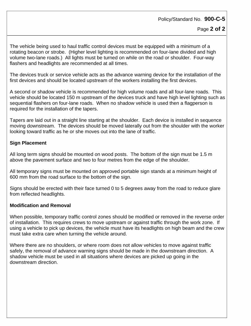
Policy/Standard No. 900-C-5
Page 2 of 2 The vehicle being used to haul traffic control devices must be equipped with a minimum of a rotating beacon or strobe. (Higher level lighting is recommended on four-lane divided and high volume two-lane roads.) All lights must be turned on while on the road or shoulder. Four-way flashers and headlights are recommended at all times. The devices truck or service vehicle acts as the advance warning device for the installation of the first devices and should be located upstream of the workers installing the first devices. A second or shadow vehicle is recommended for high volume roads and all four-lane roads. This vehicle should be located 150 m upstream of the devices truck and have high level lighting such as sequential flashers on four-lane roads. When no shadow vehicle is used then a flagperson is required for the installation of the tapers. Tapers are laid out in a straight line starting at the shoulder. Each device is installed in sequence moving downstream. The devices should be moved laterally out from the shoulder with the worker looking toward traffic as he or she moves out into the lane of traffic. Sign Placement All long term signs should be mounted on wood posts. The bottom of the sign must be 1.5 m above the pavement surface and two to four metres from the edge of the shoulder. All temporary signs must be mounted on approved portable sign stands at a minimum height of 600 mm from the road surface to the bottom of the sign. Signs should be erected with their face turned 0 to 5 degrees away from the road to reduce glare from reflected headlights. Modification and Removal When possible, temporary traffic control zones should be modified or removed in the reverse order of installation. This requires crews to move upstream or against traffic through the work zone. If using a vehicle to pick up devices, the vehicle must have its headlights on high beam and the crew must take extra care when turning the vehicle around. Where there are no shoulders, or where room does not allow vehicles to move against traffic safely, the removal of advance warning signs should be made in the downstream direction. A shadow vehicle must be used in all situations where devices are picked up going in the downstream direction.
Policy/Standard No. 900-C-6
Effective Date: April 15, 1997
Traffic Control Device: Work Zone Date of Revision: March 15, 2002 Division: Subject: Speed Limits in Construction and Maintenance Areas Page 1 of 2 Purpose From time to time it may be necessary to control traffic speeds in construction or maintenance areas by the use of regulatory speed limits. Under Section 79(6) of The Highway Traffic Act, the Minister of Infrastructure and Transportation as traffic authority may set the maximum speed at which vehicles may be driven on a highway. This authority has been delegated to the Director of Traffic Engineering for construction or maintenance areas only.
Policy The Director of Traffic Engineering may approve temporary regulatory speed limits in construction and maintenance areas on an individual basis, when the following criteria are met: It is unsafe or impossible to drive at the existing posted speed limit due to
construction roadway conditions which exist over the full 24 hour day. AND Standard construction signing is inadequate to convey to motorists that ongoing
speed reduction is required over a long section of highway. Other conditions or hazards which may warrant regulatory speed limits: Severe geometric constraints throughout the construction or maintenance area will exist over
a long period of time and over a long section of highway, e.g. two-lane two-way (2L2W) traffic on a normal four-lane divided highway.
Unusual hazards will exist over extended periods of time and over a long section of highway,
which can best be handled by speed limits, e.g. flying stones, unexpected dust conditions, large aggregate.
Speed control by the use of MAXIMUM 60 WHEN PASSING WORKERS signs (MR-96) is
inapplicable or ineffectual. RECOMMENDED: “ORIGINAL SIGNED BY” APPROVED: “ORIGINAL SIGNED BY” Director, Traffic Engineering Executive Director Highway Engineering
Policy/Standard No. 900-C-6
Page 2 of 2 Major speed differentials will exist over extended periods of time between normal highway
traffic and construction vehicles, e.g. haul roads with high traffic volumes.
Note: This does not normally refer to construction equipment such as rollers, packers, graders, scrapers, etc. which may reasonably be expected to travel at very slow speeds in construction areas, where speed control by MAXIMUM 60 WHEN PASSING WORKERS signs is appropriate.
Bridges or other structures, which for structural reasons, will not safely carry traffic at the
existing posted speed limit. Procedures Approval for speed limits must be in writing from the Director of Traffic Engineering. Use of speed limit signs must be limited to those specific sections of highway where problems exist. They must NOT be used throughout a project unless the previously listed conditions or hazards dictate. Speed limit signs must be removed immediately when the conditions change or hazards no longer exist. Advance speed limit signs (RB-5) must always be used. All speed limit signs should be enhanced by red warning flags. Speed limit signs should be repeated at minimum 1 km intervals, and following intersections. Any other existing speed limit signs should be removed or covered for the duration of this temporary speed limit. At the end of the speed limit area, a sign must be installed confirming the return to the existing posted speed limit.
Note: These approved speed limits in construction and maintenance areas are enforceable by R.C.M.P. or local police.
Policy/Standard No. 900-C-7
Effective Date: March 1, 2002
Traffic Control Device: Work Zone Division: Subject: Maximum 60 When Passing Workers Sign Page 1 of 1 Purpose It may be necessary to control traffic speeds while they are passing workers in construction or maintenance areas. The MAXIMUM 60 WHEN PASSING WORKERS sign is a regulatory and enforceable speed limit as identified under Section 56 (1) of The Highway Traffic Act.
Policy MAXIMUM 60 WHEN PASSING WORKERS signs may be installed in any active work zones where there is a need to have traffic speeds reduced below the existing regulatory speed limit.
Standard The MAXIMUM 60 WHEN PASSING WORKERS sign, when required, should be installed as close to the beginning of the active work zone as practical (See TMP-11, TMP-13, TMP-14, TMP-15 and TMP-16 for typical placement). MAXIMUM 60 WHEN PASSING WORKERS sign should be used when working within the Clear Zone. The Clear Zone requirement is 12.0 metres from the edge of the travel lane. The MAXIMUM 60 WHEN PASSING WORKERS sign should not be more than 500 meters from the active work zone and should be removed when workers are not present. This sign should not normally be required where: - The regulatory speed limit is less than 70 km/h - There is a flagperson controlling traffic If MAXIMUM 60 WHEN PASSING WORKERS sign is not applicable see Policy 900-C-6 “Speed Limits in Construction and Maintenance Areas”.
Note: The Maximum 60 When Passing Workers signs are enforceable by R.C.M.P. or local police.
RECOMMENDED: “ORIGINAL SIGNED BY” APPROVED: “ORIGINAL SIGNED BY” Director, Traffic Engineering Executive Director Highway Engineering
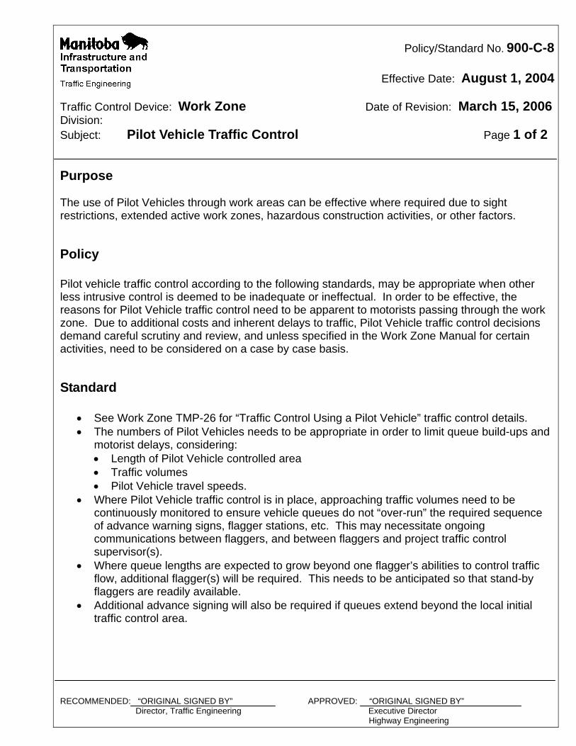
Policy/Standard No. 900-C-8
Effective Date: August 1, 2004
Traffic Control Device: Work Zone Date of Revision: March 15, 2006 Division: Subject: Pilot Vehicle Traffic Control Page 1 of 2 Purpose The use of Pilot Vehicles through work areas can be effective where required due to sight restrictions, extended active work zones, hazardous construction activities, or other factors.
Policy Pilot vehicle traffic control according to the following standards, may be appropriate when other less intrusive control is deemed to be inadequate or ineffectual. In order to be effective, the reasons for Pilot Vehicle traffic control need to be apparent to motorists passing through the work zone. Due to additional costs and inherent delays to traffic, Pilot Vehicle traffic control decisions demand careful scrutiny and review, and unless specified in the Work Zone Manual for certain activities, need to be considered on a case by case basis.
Standard
See Work Zone TMP-26 for “Traffic Control Using a Pilot Vehicle” traffic control details. The numbers of Pilot Vehicles needs to be appropriate in order to limit queue build-ups and
motorist delays, considering: Length of Pilot Vehicle controlled area Traffic volumes Pilot Vehicle travel speeds.
Where Pilot Vehicle traffic control is in place, approaching traffic volumes need to be continuously monitored to ensure vehicle queues do not “over-run” the required sequence of advance warning signs, flagger stations, etc. This may necessitate ongoing communications between flaggers, and between flaggers and project traffic control supervisor(s).
Where queue lengths are expected to grow beyond one flagger’s abilities to control traffic flow, additional flagger(s) will be required. This needs to be anticipated so that stand-by flaggers are readily available.
Additional advance signing will also be required if queues extend beyond the local initial traffic control area.
RECOMMENDED: “ORIGINAL SIGNED BY” APPROVED: “ORIGINAL SIGNED BY” Director, Traffic Engineering Executive Director Highway Engineering
Policy/Standard No. 900-C-8
Page 2 of 2
The extent of the area under Pilot Vehicle traffic control must be limited in order to: reduce queuing times and delays reduce project costs (by limiting numbers of the required Pilot Vehicles) reduce queuing hazards such as rear-end collisions maintain motorist patience and “buy-in” for the attendant delays
Variable Message Signs (VMS) should always be considered in order to provide additional “high level” advance warning to approaching traffic. The preferred message is “Prepare to Stop xx km.” Consult Traffic Engineering for other particular messages relating to local conditions or problems.
Pilot Vehicle drivers must obey all rules of the road, and adhere to the directions of flaggers and all other work zone traffic controls, including posted speed limits.
Pilot Vehicle drivers must tailor their accelerations and travel speeds according to the mix of traffic and to road conditions in order to avoid undesirable gaps in the vehicle platoon and subsequent overtaking and “catch up” speeding actions by following vehicles.
For typical sign placement and lighting, see drawing below.
Policy/Standard No. 900-D-1
Effective Date: April 15, 1997
Traffic Control Device: Work Zone Date of Revision: March 15, 2002 Division: Subject: Traffic Control on Low Speed Roads Page 1 of 1 Purpose Protection of the travelling public and the safety of workers is paramount. However these must be weighed against the cost and time involved with the installation and removal of the necessary traffic control devices. Traffic control in low speed areas requires special consideration particularly at intersections and where a number of accesses are present.
Policy Special traffic management strategies are required on Provincial Trunk Highways and Provincial Roads where posted speed limits are 60 km/h or lower when work is being done or in the vicinity of the road surface by Department staff, utilities, or contractors. Standard The Traffic Engineering Branch or the Regional Safety Training Facilitator should be contacted to discuss traffic control options. RECOMMENDED: “ORIGINAL SIGNED BY” APPROVED: “ORIGINAL SIGNED BY” Director, Traffic Engineering Executive Director Highway Engineering
Policy/Standard No. 900-E-1
Effective Date: April 15, 1997
Traffic Control Device: Work Zone Date of Revision: March 15, 2002 Division: Subject: Off-Road Operations Page 1 of 1 Purpose Off-road operations include all activities which are done away from the surface of the road but within the right-of-way. The duration of the operation is typically greater than ten minutes. Safety of the motorist and workers requires that some form of advance warning be provided and maintained. Protection of the travelling public, and the safety of workers is paramount. However, these must be weighed against the cost and time involved with the installation and removal of the necessary traffic control devices. Definition Off Road Operations - Include any operation where the activity is off the road surface but within the highway right-of-way. Off-road operations include maintenance activities including culvert cleaning, sign installation, and any other activity including work done by utilities where workers are exposing the motorist to possible hazards off the road surface.
Policy Where work using workers and/or equipment is being done on any Provincial Trunk Highway or Provincial Road, away from the road surface but within the highway right-of-way, and the duration of that work is greater than 10 minutes, a minimum level of traffic control must be established and maintained for the time that workers or equipment are present. Standard Traffic control must consist of at least the minimum installation as described in the following Traffic Management Plans (TMP): See Drawings TMP-1, TMP-2. The work zone must be left in a safe condition prior to workers and equipment leaving the work site. All excavations must be closed or protected.
RECOMMENDED: “ORIGINAL SIGNED BY” APPROVED: “ORIGINAL SIGNED BY” Director, Traffic Engineering Executive Director Highway Engineering
Policy/Standard No. 900-E-2
Effective Date: April 15, 1997
Traffic Control Device: Work Zone Date of Revision: March 15, 2002 Division: Subject: Shoulder Work Page 1 of 1 Purpose When work activities are restricted to the shoulder of the road, the disruption to traffic flow may be decreased, but the motorist requires advance warning that men and equipment are in a position to be a potential hazard. Protection of the travelling public and the safety of workers is paramount. However, these must be weighed against the cost and time involved with the installation and removal of the necessary traffic control devices. Policy Where work is being done on any Provincial Trunk Highway or Provincial Road on the shoulder of the road or in the median of a divided road, a minimum level of traffic control must be established and maintained for the duration of the time that workers or equipment are present. Standard Traffic control must consist of at least the minimum installation as described in the following Traffic Management Plans (TMP):
TMP-2 TMP-3 TMP-4 TMP-5 TMP-6 TMP-7 TMP-7A TMP-8
RECOMMENDED: “ORIGINAL SIGNED BY” APPROVED: “ORIGINAL SIGNED BY” Director, Traffic Engineering Executive Director Highway Engineering
Policy/Standard No. 900-E-3
Effective Date: November 10, 2006
Traffic Control Device: Work Zone Date of Revision: June 26, 2007 Division: Subject: Bridge Inspection Page 1 of 2 Purpose Bridge and culvert inspection activities causing disruption to traffic flow may be similar to work on the surface of the road, or off the road. A work zone located on the surface of a bridge may create an extraordinary hazard to workers and to the travelling public as the confined spaces of the bridge eliminate any possible escape routes. The motorist, however, may not typically require enhanced warning of potential hazards. Protection of the travelling public and the safety of workers is paramount. However, these must be weighed against the cost and time involved with the installation and removal of the necessary traffic control devices. Policy Where routine inspections are being done on the surface of any bridge on any Provincial Trunk Highway or Provincial Road, a minimum level of traffic control must be established and maintained for the duration of the time that workers or equipment are present. Standard traffic management plans are sufficient in most situations. Where unusual conditions are anticipated, preplanning and discussions with the Traffic Operations Engineer are required. Standard Traffic control must consist of at least the minimum installation as described in the appropriate Traffic Management Plans (TMP). The following table will provide additional guidelines for the implementation of traffic control on bridge inspection projects. Additional enhancements may be considered when traffic conditions warrant. RECOMMENDED: “ORIGINAL SIGNED BY” APPROVED: “ORIGINAL SIGNED BY” Director, Traffic Engineering Executive Director Highway Engineering
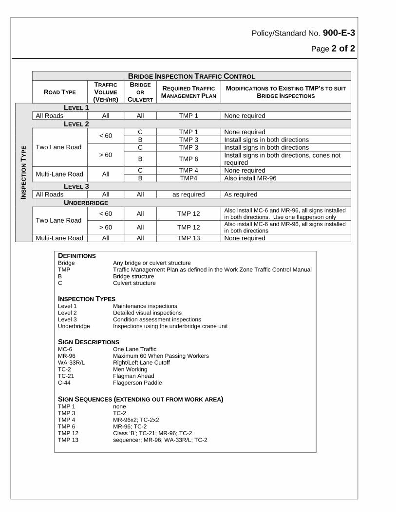
Policy/Standard No. 900-E-3
Page 2 of 2
BRIDGE INSPECTION TRAFFIC CONTROL
ROAD TYPE TRAFFIC
VOLUME
(VEH/HR)
BRIDGE
OR
CULVERT
REQUIRED TRAFFIC
MANAGEMENT PLAN MODIFICATIONS TO EXISTING TMP’S TO SUIT
BRIDGE INSPECTIONS
LEVEL 1 All Roads All All TMP 1 None required LEVEL 2
C TMP 1 None required < 60
B TMP 3 Install signs in both directions C TMP 3 Install signs in both directions Two Lane Road
> 60 B TMP 6
Install signs in both directions, cones not required
C TMP 4 None required Multi-Lane Road All
B TMP4 Also install MR-96 LEVEL 3 All Roads All All as required As required UNDERBRIDGE
< 60 All TMP 12 Also install MC-6 and MR-96, all signs installed in both directions. Use one flagperson only Two Lane Road
> 60 All TMP 12 Also install MC-6 and MR-96, all signs installed in both directions
INS
PE
CT
ION
TY
PE
Multi-Lane Road All All TMP 13 None required
DEFINITIONS Bridge Any bridge or culvert structure TMP Traffic Management Plan as defined in the Work Zone Traffic Control Manual B Bridge structure C Culvert structure INSPECTION TYPES Level 1 Maintenance inspections Level 2 Detailed visual inspections Level 3 Condition assessment inspections Underbridge Inspections using the underbridge crane unit SIGN DESCRIPTIONS MC-6 One Lane Traffic MR-96 Maximum 60 When Passing Workers WA-33R/L Right/Left Lane Cutoff TC-2 Men Working TC-21 Flagman Ahead C-44 Flagperson Paddle
SIGN SEQUENCES (EXTENDING OUT FROM WORK AREA) TMP 1 none TMP 3 TC-2 TMP 4 MR-96x2; TC-2x2 TMP 6 MR-96; TC-2 TMP 12 Class ‘B’; TC-21; MR-96; TC-2 TMP 13 sequencer; MR-96; WA-33R/L; TC-2
Policy/Standard No. 900-F-1
Effective Date: April 15, 1997
Traffic Control Device: Work Zone Date of Revision: March 15, 2002 Division: Subject: Mobile Operations Page 1 of 2 Purpose Mobile operations present a special set of traffic control problems. Protection of the travelling public, and the safety of workers is paramount. However, these must be weighed against the cost and time involved with the installation and removal of the necessary traffic control devices. The speed of the operation and the duration at any one work location makes the signing of the work site using standard techniques difficult and hard to justify from a cost perspective. However, safety of the motorist and workers requires that some form of advance warning be provided and maintained.
Definition Mobile Operations - Include any operation where the maximum duration of any activity on or near the road surface is less than 5 minutes for any 30 m length of work zone. Mobile operations include maintenance activities which are of very short duration, including “Pitch and Run”, “Sign Washing”, and any other activity where workers are exposed to traffic for short periods of time.
Policy Whenever a construction and maintenance activity can be identified as a mobile operation, a minimum level of traffic control must be established and maintained for the duration of the work. This policy/standard is limited to “daylight hours” only. Whenever mobile operations must occur during hours of darkness, a Traffic Management Plan (TMP) must be approved by the Director of Traffic Engineering or designate. RECOMMENDED: “ORIGINAL SIGNED BY” APPROVED: “ORIGINAL SIGNED BY” Director, Traffic Engineering Executive Director Highway Engineering
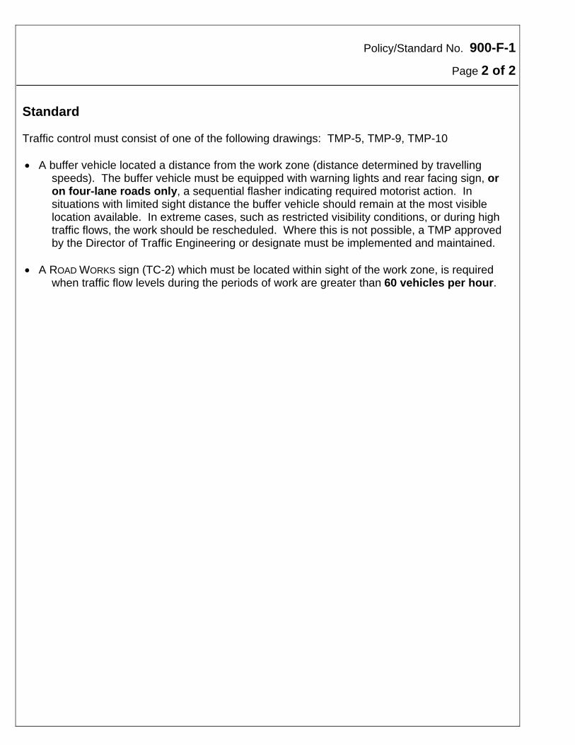
Policy/Standard No. 900-F-1
Page 2 of 2 Standard Traffic control must consist of one of the following drawings: TMP-5, TMP-9, TMP-10 A buffer vehicle located a distance from the work zone (distance determined by travelling
speeds). The buffer vehicle must be equipped with warning lights and rear facing sign, or on four-lane roads only, a sequential flasher indicating required motorist action. In situations with limited sight distance the buffer vehicle should remain at the most visible location available. In extreme cases, such as restricted visibility conditions, or during high traffic flows, the work should be rescheduled. Where this is not possible, a TMP approved by the Director of Traffic Engineering or designate must be implemented and maintained.
A ROAD WORKS sign (TC-2) which must be located within sight of the work zone, is required
when traffic flow levels during the periods of work are greater than 60 vehicles per hour.
Policy/Standard No. 900-F-2
Effective Date: April 15, 1997
Traffic Control Device: Work Zone Date of Revision: March 15, 2002 Division: Subject: Fast Moving Operations - Page 1 of 2 Benkelman Beam (Pavement Deflection) Purpose Fast moving operations present a special set of traffic control problems. Protection of the travelling public, and the safety of workers is paramount. However, these must be weighed against the cost and time involved with installing and removing the necessary traffic control devices. The lateral position of the flagperson, i.e. distance away from the relative safety of the shoulder, also must weigh personal safety against the flagperson's ability to adequately control and warn traffic. Definition Fast Moving Operations will generally be considered to include any operation which stops on the travelled surface of the road for a period not exceeding 10 minutes in daylight hours only.
This standard covers Benkelman beam (pavement deflection) only. Due to variations in their operations, other fast moving operations such as B-30 soil drill truck, nuclear density testing, coring unit, profilometer and "hi-lo" measurements have similar complimentary standards.
Policy This standard covers the self-propelled Benkelman beam operation only. Due to the continuous mobile nature of this operation, static advance signing is not feasible. Vehicle and equipment mounted signs and lights must provide adequate warning. This policy applies to all Provincial Trunk Highways and Provincial Roads.
Standard Traffic control should consist of at least the following (see drawing S-TMP-1): Symbolic FLAGMAN sign (TC-21) or rectangular fluorescent orange warning sign FREQUENT
STOPS mounted on rear of trailing flagman's vehicle (1/2 ton or van). RECOMMENDED: “ORIGINAL SIGNED BY” APPROVED: “ORIGINAL SIGNED BY” Director, Traffic Engineering Executive Director Highway Engineering
Policy/Standard No. 900-F-2
Page 2 of 2
Flagpersons stationed in the closed lane, approximately 1 m from roadway centreline, at the
front of the flagperson's vehicle (no closer than 15 m to the vehicle) to allow a clear "escape route" for the flagperson, and to provide refuge from a possible errant vehicle.
Five-ton "deflection unit" vehicle with the following warning devices operating: front and rear
facing "wig-wag" amber flashers, high beam headlamps, and four-way flashers. A rectangular fluorescent orange warning sign FREQUENT STOPS and fluorescent orange/black
hazard marker signs should be mounted on the rear of the five-ton deflection unit. (Signs should be removed or covered during travel to and from the highway under measurement.)
The five-ton deflection unit vehicle is required to be parked in the closed lane during pavement
deflection measurements. Flagperson must be in position before Benkelman beam operator proceeds onto roadway
surface. For urban areas with speed limits under 60 km/h, traffic controls may be compressed to 50 m
overall (sign to deflection unit vehicle). Additional care should be exercised to ensure accesses from driveways, etc. are considered.
Policy/Standard No. 900-F-3
Effective Date: April 15, 1997
Traffic Control Device: Work Zone Date of Revision: March 15, 2002 Division: Subject: Fast Moving Operations-Soil Drill Truck/Coring Operations Page 1 of 2 Purpose Fast moving operations present a special set of traffic control problems. Protection of the travelling public, and the safety of workers is paramount. However, these must be weighed against the costs and time involved with installing and removing the necessary traffic control devices. The lateral position of the flagperson, i.e. distance away from the relative safety of the shoulder, also must weigh personal safety against the flagperson's ability to adequately control and warn traffic.
Definition Fast Moving Operations will generally be considered to include any operation which stops on the travelled surface of the road for a period not exceeding 10 minutes in daylight hours only.
This standard covers B-30 soil drill truck and coring vehicle operations only. Due to variations in their operations, other fast moving operations such as nuclear density testing, Benkelman beam testing and "hi-lo" measurements have similar complimentary standards.
Policy This standard covers the B-30 soils drill truck and coring vehicle operations only. Due to the continuous mobile nature of this operation, static advance signing is not feasible. Vehicle and equipment mounted signs and lights must provide adequate warning. This policy applies to all Provincial Trunk Highways and Provincial Roads. RECOMMENDED: “ORIGINAL SIGNED BY” APPROVED: “ORIGINAL SIGNED BY” Director, Traffic Engineering Executive Director Highway Engineering
Policy/Standard No. 900-F-3
Page 2 of 2
Standard Traffic control shall consist of at least the following (see drawing S-TMP-2): Symbolic Flagman sign (TC-21) on portable sign stand or sign trailer. Flagperson stationed in the closed lane, approximately 1 m from roadway centreline. Symbolic Road Work sign (TC-2) on two-way roadways for traffic in opposite direction. Ten traffic cones; 5 required for tapered lane closure, 5 recommended on tangent as shown
on S-TMP-2. When required, the technicians truck shall park on the shoulder behind the soil drill
truck/coring vehicle. This vehicle shall have a rotating beacon operating. The drill truck/coring unit is to be parked in the closed lane. Signs shall be supplemented by fluorescent red flags. Flags are also highly desirable on the
soils drill truck/coring unit. This is a minimum standard. Where traffic volumes or sight restrictions create a problem, a
second Flagman sign and a second flagperson for traffic in the opposite direction will be required on two-way roadways. The distance to the flagperson and sign will be 70 m and 150 m respectively, from the soils drill truck.
For urban areas with speed limits under 60 km/h, traffic controls may be compressed to
50 m overall (sign to soil drill truck/coring unit). Additional care should be exercised to ensure accesses from driveways, etc. are considered.
Policy/Standard No. 900-F-4
Effective Date: April 15, 1997
Traffic Control Device: Work Zone Date of Revision: March 15, 2002 Division: Subject: Fast Moving Operations - Profilograph Unit Page 1 of 2 Purpose Fast moving operations present a special set of traffic control problems. Protection of the travelling public, and the safety of workers is paramount. Every reasonable effort must be taken to enhance the visibility of slow-moving equipment where its unexpected presence and slow speed may otherwise demand drastic avoidance manoeuvres by highway traffic.
Definition Fast Moving Operations will generally be considered to include any operation which travels continuously or stops on the travelled surface of the road for a period not exceeding 10 minutes in daylight hours only.
Policy This standard covers the self-propelled profilograph unit only. Due to the continuous mobile nature of this operation, static advance signing is not feasible. Vehicle and equipment mounted signs and lights must provide adequate warning. This policy applies to all Provincial Trunk Highways and Provincial Roads.
Standard The profilograph operation effectively closes the lane being evaluated/measured. Traffic
must find its way around the operation on two-lane two-way (2L2W) highways by choosing appropriate available gaps in the oncoming traffic stream.
For traffic safety reasons the profilograph unit must restrict its operation to daylight hours
only. Late season operation must be evaluated to determine that low sunlight angles do not obscure equipment visibility.
RECOMMENDED: “ORIGINAL SIGNED BY” APPROVED: “ORIGINAL SIGNED BY” Director, Traffic Engineering Executive Director Highway Engineering
Policy/Standard No. 900-F-4
Page 2 of 2
Traffic control shall consist of at least the following (see drawing S-TMP-3): A trailing vehicle comprising a suitable vehicle towing the profilograph trailer, following
approximately 15 m behind the self propelled profilograph unit and equipped with the following:
a special black on fluorescent reflective orange rearward facing hinged sign “Yield To
Approaching Traffic”
highly visible black/fluorescent orange diagonal cross-hatched markings on the back of
the trailer unit
extremely bright flashing yellow strobe lights (Whelen model 97 or equivalent) facing front and rear, mounted as high as possible on the trailing vehicle trailer
a rear-facing sequential flashing "arrow board" - the arrow board should flash in the
non-directional "diamond" or four-corner mode during operation on 2L2W roadways, and indicate the direction for following traffic to pass (left or right as applicable) only on multi-lane roadways
fluorescent orange flags (in specially constructed flagholders) at the rear of the trailing
vehicle trailer unit
headlights and forward facing strobe lights on the profilograph tractor unit (similar to those on the trailing vehicle trailer)
fluorescent orange pennant mounted at the front and rear of the profilograph beam
Where traffic volumes, highway geometry, or other conditions dictate, (and the operation
cannot reasonably be rescheduled), an additional trailing vehicle may be necessary. This vehicle operating on the shoulder should be equipped with flashing or rotating amber warning lights, a special black-on-fluorescent orange sign SLOW MOVING EQUIPMENT AHEAD (see sketch), and should follow the first trailing vehicle at a distance of
approximately 300 m. As with other fast moving operations, profilograph operators must continually evaluate traffic
conditions and be prepared to discontinue operations to allow following traffic queues to pass, or to abandon operations until conditions improve.
Policy/Standard No. 900-F-5
Effective Date: April 15, 1997
Traffic Control Device: Work Zone Date of Revision: March 15, 2002 Division: Subject: Fast Moving Operations/Nuclear Density Testing Page 1 of 3 Purpose Fast moving operations present a special set of traffic control problems. Protection of the travelling public, and the safety of workers is paramount. However, these must be weighed against the cost and time involved with installing and removing the necessary traffic control devices. The lateral position of the flagperson, i.e. distance away from the relative safety of the shoulder, also must weigh personal safety against the flagperson's ability to adequately control and warn traffic. Definition Fast Moving Operations will generally be considered to include any operation which stops on
the travelled surface of the road for a period not exceeding 10 minutes in daylight hours only. This standard covers nuclear density testing only. Due to variations in their operations, other fast moving operations such as B-30 soil drill truck, coring unit, Benkelman beam testing, profilometer, and "hi-lo" measurements have similar complementary standards.
Policy This standard covers nuclear density testing only. Due to the continuous mobile nature of this operation, static advance signing is not feasible. Vehicle and equipment mounted signs and lights must provide adequate warning. This policy applies to all Provincial Trunk Highways and Provincial Roads and all surfacing and grading projects open to traffic. RECOMMENDED: “ORIGINAL SIGNED BY” APPROVED: “ORIGINAL SIGNED BY” Director, Traffic Engineering Executive Director Highway Engineering
Policy/Standard No. 900-F-5
Page 2 of 3
Traffic control should consist of at least the following (see drawing S-TMP-4): Symbolic FLAGMAN sign (TC-21) on portable sign stand, sign trailer or shadow vehicle. Flagperson stationed in the closed lane, approximately 1 m from roadway centerline. Ten traffic cones; 5 required for tapered lane closure, 5 recommended on tangent as shown
on S-TMP-4. Density inspector's vehicle equipped with the following warning devices: approved rotating
beacon or strobe, rear-facing "wig-wag" amber flashers, and headlights on high beam. If headlights and "wig-wag" amber flashers are operating, use of rotating beacon or strobe is optional.
The density inspector's vehicle is to be parked in the closed lane. The density inspector's vehicle must be capable of carrying all signs, lights and cones required to create the work zone as per the standard.
Signs must be supplemented by fluorescent red flags. Flags are also highly desirable on the
density inspector's vehicle.
This is a minimum standard. Where traffic volumes or sight restrictions create a problem, a second sign and a second flagperson for traffic in the opposite direction will be required on two-way roadways. The distance to the flagperson and sign will be 70 m and 150 m respectively, from the density inspector's vehicle.
Visibility (to the motorist) of the nuclear density testing operation is an ongoing problem. Extra
care must be taken to ensure that all traffic control devices are in good condition, clean, and placed properly. All warning lights must be clean and operating effectively. All workers must be attired in clean, highly visible department approved safety vest and head wear.
The flagperson may be located up to 500 m from the symbolic FLAGMAN AHEAD sign only
where the flagperson is visible from the sign location, and no major accesses or intersections exist in the area between sign and flagperson.
For urban areas with speed limits under 60 km/h, traffic controls may be compressed to 50 m
overall (sign to density inspector's vehicle). In certain circumstances, i.e. parallel or diagonal parking, sign use may be impractical. Accesses from driveways, etc. may have to be taken into consideration in determining locations of cones and flagpersons. (Crews are expected to base their decisions regarding sign use in urban areas, on experience and common sense to ensure worker and public safety is not compromised.)
Policy/Standard No. 900-F-5
Page 3 of 3
Where a shadow vehicle is used (recommended on high volume two-lane roadways) the
shadow vehicle should be located half on the shoulder, half on the travel lane. The shadow vehicle must be equipped with rear-facing "wig wag" amber flashers. The flagman ahead sign must be mounted on the right hand rear of the shadow vehicle
Policy/Standard No. 900-F-6
Effective Date:
Traffic Control Device: Work Zone Date of Revision: March 15, 2002 Division: Subject: Fast Moving Operations – Hi-Low Vehicle Page 1 of 2 Purpose Fast moving operations present a special set of traffic control problems. Protection of the travelling public, and the safety of workers is paramount. Every reasonable effort must be taken to enhance the visibility of slow-moving equipment where its unexpected presence and slow speed may otherwise demand drastic avoidance manoeuvres by highway traffic.
Definition Fast Moving Operations will generally be considered to include any operation which travels continuously or stops on the travelled surface of the road for a period not exceeding 10 minutes in daylight hours only.
Policy This standard covers the Hi-Low Vehicle only. Due to the continuous mobile nature of this operation, static advance signing is not feasible. Vehicle mounted signs and lights must provide adequate warning. This policy applies to all Provincial Trunk Highways and Provincial Roads.
Standard The Hi-Low operation effectively closes the lane being evaluated/measured. Traffic must find
its way around the operation on two-lane two-way (2L2W) highways by choosing appropriate available gaps in the oncoming traffic stream.
For traffic safety reasons the Hi-Low vehicle must restrict its operation to daylight hours only.
Late season operation must be evaluated to determine that low sunlight angles do not obscure equipment visibility.
RECOMMENDED: “ORIGINAL SIGNED BY” APPROVED: “ORIGINAL SIGNED BY” Director, Traffic Engineering Executive Director Highway Engineering
Policy/Standard No. 900-F-6
Page 2 of 2
Traffic control shall consist of at least the following (see drawing S-TMP-5): A Hi-Low Vehicle equipped with the following:
a black on fluorescent reflective orange rearward facing sign PASS WITH CARE extremely bright flashing yellow strobe light (Whelen model 97 or equivalent) facing
front and rear, a rear-facing sequential flashing arrow board - the arrow board should flash in the
non-directional “diamond” or four-corner mode during operation on 2L2W roadways, and indicate the direction for following traffic to pass (left or right as applicable) only on multi-lane roadways
fluorescent orange flags at the front and rear of the Hi-Low vehicle As with other fast moving operations, Hi-Low vehicles must continually evaluate traffic
conditions and be prepared to discontinue operations to allow following traffic queues to pass, or to abandon operations until conditions improve.
Policy/Standard No. 900-F-7
Effective Date: January 11, 2000
Traffic Control Device: Work Zone Date of Revision: March 15, 2002 Division: Subject: Fast Moving Operations – Self-Propelled Asphalite Unit Page 1 of 2 Purpose Fast moving operations present a special set of traffic control problems. Protection of the travelling public, and the safety of workers is paramount. Every reasonable effort must be taken to enhance the visibility of slow-moving equipment where its unexpected presence and slow speed may otherwise demand drastic avoidance manoeuvres by highway traffic.
Definition Fast Moving Operations will generally be considered to include any operation which travels continuously or stops on the travelled surface of the road for a period not exceeding 10 minutes in daylight hours only.
Policy This standard covers the self-propelled Asphalite unit only. This policy applies to all Provincial Trunk Highways and Provincial Roads.
Standard The Asphalite operation effectively closes the lane being worked on. Traffic must find its way
around the operation on two-lane two-way (2L2W) highways by choosing appropriate available gaps in the oncoming traffic stream.
For traffic safety reasons the Asphalite unit must restrict its operation to daylight hours only.
Late season operation must also be evaluated to determine that low sunlight angles do not obscure equipment visibility.
RECOMMENDED: “ORIGINAL SIGNED BY” APPROVED: “ORIGINAL SIGNED BY” Director, Traffic Engineering Executive Director Highway Engineering
Policy/Standard No. 900-F-7
Page 2 of 2
Traffic control shall consist of at least the following (see drawing S-TMP-7): A trailing vehicle, following approximately 40 m behind the self propelled Asphalite unit and
equipped with the following:
a special black on reflective white rearward facing sign PASS WITH CARE.
rotating beacon, mounted as high as possible A rear-facing sequential flashing "arrow board" must be equipped on either the Asphalite unit
or the trailing vehicle. The arrow board should flash in the non-directional "diamond" or four-corner mode during operation on 2L2W roadways, and indicate the direction for following traffic to pass (left or right as applicable) only on multi-lane roadways.
The Asphalite unit must operate with rotating beacon and headlights on high beam. Flying Stones signs (MW-94) should be installed, spaced not more than 5 km apart facing
both directions of traffic and shall be left in place for a period of at least 24 hours after work is completed, or longer as required.
As with other fast moving operations, Asphalite operators must continually evaluate traffic
and visibility conditions and be prepared to discontinue operations to allow following traffic queues to pass, or to abandon operations until conditions improve.
When working in low-speed urban areas or low volume rural areas, the trailing vehicle is
recommended but not required, provided the Asphalite unit is equipped with a flashing arrow board.
Policy/Standard No. 900-F-8
Effective Date: January 11, 2000
Traffic Control Device: Work Zone Date of Revision: March 15, 2002 Division: Subject: Mobile Operations – Maintenance Gravelling Page 1 of 2 Purpose Mobile operations present a special set of traffic control. Protection of the travelling public and the safety of workers is paramount. However, these must be weighed against the cost and time involved with the installation and removal of the necessary traffic control devices. The speed of the operation and the duration at any one work location makes the signing of the work site using standard techniques difficult and hard to justify from a cost perspective. However, safety of the motorist and workers requires that some form of advance warning be provided and maintained.
Definition Mobile Operations - Include any operation where the maximum duration of any activity on or near the road surface is less than 5 minutes for any 30 m length of work zone. Mobile operations include maintenance activities which are of very short duration, including “Pitch and Run”, “Sign Washing”, and any other activity where workers are exposed to traffic for short periods of time.
Policy This standard covers the maintenance gravelling of gravel roads. This policy/standard is limited to “daylight hours” only. RECOMMENDED: “ORIGINAL SIGNED BY” APPROVED: “ORIGINAL SIGNED BY” Director, Traffic Engineering Executive Director Highway Engineering
Policy/Standard No. 900-F-8
Page 2 of 2 Standard Traffic control must consist of the following (see drawing S-TMP-8): ROAD WORKS signs (TC-2) or “Truck Gravelling” sign placed at both ends of the work zone. The Work Zone length must not be greater than 10 km. All “gravel trucks” must have headlights on when gravelling.
Policy/Standard No. 900-F-9
Effective Date: January 31, 2002
Traffic Control Device: Work Zone Date of Revision: December 31, 2004 Division: Subject: Traffic Control for Planned Traffic Signal Works Page 1 of 2 Purpose Traffic control during signal maintenance, construction and repair is necessary to ensure the safety of all motorists, pedestrians and workers.
Policy This policy applies to all intersections where traffic signals will be temporarily inoperative or where signal displays may be blocked or otherwise affected by the work in progress, or motorists may be distracted or confused by the presence of workers or signal vehicles.
Standard The following standards are applicable to planned traffic signal maintenance, construction and repairs: 1. For all planned work except minor inspections or non-intrusive activities such as controller
adjustments, the TC-2 (Men Working) sign should be placed on all affected approaches (refer to S-TMP-3 and S-TMP-4).
For urban areas where signing on the right hand side may be obscured by parked vehicles, signs may be more effective if placed in the median of a divided street or roadway.
2. For all planned work where traffic signals will be temporarily inoperative (i.e. cutovers,
controller replacement, etc.), the TC-2 (men working sign) and MW-121 (signals under repair ahead sign) should be placed on all approaches (refer to S-TMP-9 and S-TMP-10).
3. Additional traffic control for planned traffic signal repairs with signals inoperative should be as
follows:
For lower speed (<70 km/h) – Lower Volume intersections (i.e. Gimli, Dauphin, The Pas) (refer to S-TMP-9): Traffic should normally be controlled with 4-way stop signs with advance stop ahead signs. The signal crew should be mindful and watchful of traffic and pedestrians, and if necessary, aid pedestrians who wish to cross the roadway.
RECOMMENDED: “ORIGINAL SIGNED BY” APPROVED: “ORIGINAL SIGNED BY” Director, Traffic Engineering Executive Director Highway Engineering
Policy/Standard No. 900-F-9
Page 2 of 2
Low Speed-High Volume on Main Road, Low Volume on cross road intersections (i.e. PTH 9 at Riverglenn, 1st/Rosser (Brandon), etc.) (refer to S-TMP-10): Traffic would normally be controlled with 2-way stop signs, flagman ahead signs and Department flagpeople.
Low Speed-High Volume on all approaches (i.e. Richmond/18th Street, 18th Street/Park,
etc.) (refer to S-TMP-10): Traffic would normally be controlled with 2-way stop signs, flagman ahead signs and Police (City or RCMP).
High Speed-High Volume (i.e. 100/St. Mary’s, 1/16, etc.) (refer to S-TMP-10): Traffic would
normally be controlled with 2-way stop signs, flagman ahead signs and Police (City or RCMP).
High Speed-Lower Volume (i.e. 1/Blumberg, 1/Odeon, etc.): To be reviewed and approved
by the Traffic Operations Engineer on a site-by-site basis.
Policy/Standard No. 900-F-10
Effective Date: March 15, 2002
Traffic Control Device: Work Zone Division: Subject: Fast Moving Operation – Pavement Marking Page 1 of 2 Purpose Fast moving operations present a special set of traffic control problems. Protection of the travelling public and the safety of workers is paramount. Every reasonable effort must be taken to enhance the visibility of slow-moving equipment where its unexpected presence and slow speed may otherwise demand avoidance manoeuvres by highway traffic.
Definition Fast Moving Operations will generally be considered to include any operation which travels continuously or stops on the travelled surface of the road for a period not exceeding 10 minutes in daylight hours only.
Policy This standard covers the pavement marking truck and paint supply truck only. Due to the continuous mobile nature of this operation, static advance signing is not feasible. Vehicle and equipment mounted signs and lights must provide adequate warning. This policy applies to all Provincial Trunk Highways and Provincial Roads.
Standard Traffic control should consist of at least the following (see drawings S-TMP-11 and S-TMP-12): A trailing vehicle, following approximately 400 m behind the pavement marking vehicle and
equipped with the following:
A rearward facing “ WET PAINT” sign Rotating beacon Rear-facing sequential flashing arrow
RECOMMENDED: “ORIGINAL SIGNED BY” APPROVED: “ORIGINAL SIGNED BY” Director, Traffic Engineering Executive Director Highway Engineering
Policy/Standard No. 900-F-10
Page 2 of 2
Pavement Marking Vehicle equipped with the following warning devices:
Rotating beacon Front and rear-facing warning lights Rear-facing “Pass With Care” sign Optional - rear-facing sequential flashing arrow
Paint Supply / Sweeper Vehicle operating 1-5 km in front of the Pavement Marking Vehicle
equipped with the following warning devices:
Rotating beacon Front and rear-facing warning lights
Policy/Standard No. 900-F-11
Effective Date: March 30, 2002
Traffic Control Device: Work Zone Date of Revision: February 28, 2006 Division: Subject: Sealcoat Operations Page 1 of 2 Purpose Sealcoat operations present a special set of traffic control problems. Protection of the travelling public and the safety of workers is paramount. However, these must be weighed against the cost and time involved with installing and removing the necessary traffic control devices. Sealcoat projects are unique in that vehicles are at a greater risk of damage by stones from passing vehicles than would normally be expected on a surfaced roadway. Most drivers are unaware of the details of sealcoat operations and must be given additional information to ensure they are aware of the potential hazards.
Policy This standard covers the sealcoat operation only. Prior to commencing a sealcoat operation over a paved surface, the start and end of all passing restrictions must be signed using the “No Passing” (RB-31) sign and the “Passing Permitted” (RB-32) sign. Windshield Hazard signs (MW-94) should be installed at the beginning of all sealcoat
projects over 3 km in length. Windshield Hazard signs are normally not required where the sealcoat work is being done as part of a large construction project where project boards and gates are in place.
Traffic control should consist of at least the following in addition to standard work-zone signing(see drawing TMP-29): Symbolic “Flying Stones” sign (MW-94), “No Passing” sign (RB-31) and regulatory
“Maximum 40 When Meeting Traffic” sign (MR-136) repeated at minimum 3 km intervals throughout the length of the project. These signs should be maintained as necessary during and immediately after the sealcoating operation until the “flying stones” hazard has been minimized.
Flagperson stationed at each end of the active work area where sealcoating is in progress. RECOMMENDED: “ORIGINAL SIGNED BY” APPROVED: “ORIGINAL SIGNED BY” Director, Traffic Engineering Executive Director Highway Engineering
Policy/Standard No. 900-F-11
Page 2 of 2 Optional Pilot Vehicle and additional flagpeople, as required, based on traffic volume and
road geometry. See Policy/Standard 900-C-8 for Pilot Vehicle Traffic Control. Portable radar-based Speed Reader Boards may be used at both ends of all rural sealcoat
operations when the “flying stone” hazard is present, to provide motorists with additional travel speed reminders. Reader Board use should also be considered on an as-required basis for urban sealcoat operations.
Policy/Standard No. 900-G-1
Effective Date: April 15, 1997
Traffic Control Device: Work Zone Date of Revision: March 15, 2002 Division: Subject: Short Term Lane Closures Page 1 of 1 Purpose Protection of the travelling public and the safety of workers is paramount. However, these must be weighed against the cost and time involved with the installation and removal of the necessary traffic control devices. Short term lane closures are required to allow workers to accomplish their activities in a safe and efficient manner. These lane closures must be installed whenever work activities disrupt the normal flow of traffic.
Definition Short Term means a lane closure that is installed and removed on the same day, and is applicable during daylight periods only.
Policy Whenever construction and maintenance activities disrupt the normal flow of traffic on Provincial Trunk Highways or Provincial Roads, or cause workers or motorists to be in a hazardous situation on these roads, a Traffic Management Plan (TMP) must be developed, installed, and maintained for the duration of the disruption or condition. When the condition will be returned to normal during one daylight period “short term” traffic control methods may be used. Standard Traffic control should consist of one of the following Traffic Management Plans:
TMP-11 - Two-Lane Road - Yield to Oncoming Traffic (<60 vehicles per hour) TMP-12 - Single Lane Closed on Two-Lane Road (Volume > 60 vehicles per hour) TMP-13 - Right Lane Closed on Four-Lane Divided Road TMP-14 - Left Lane Closed on Four-Lane Divided Road
RECOMMENDED: “ORIGINAL SIGNED BY” APPROVED: “ORIGINAL SIGNED BY” Director, Traffic Engineering Executive Director Highway Engineering
Policy/Standard No. 900-G-2
Effective Date: April 15, 1997
Traffic Control Device: Work Zone Date of Revision: March 15, 2002 Division: Subject: Daylight Detour – Flagpersons Required Continuously Page 1 of 2 Purpose Short term detours present a special set of traffic control problems. Protection of the travelling public, and the safety of workers is paramount. However, these must be weighed against the cost and time involved with installing and removing the necessary traffic control devices. Flagpersons, used effectively, can be expected to substitute for some other traffic control devices. However, heavy traffic volumes, limited sight distances, or poor visibility conditions may require additional measures to ensure motorist and worker safety.
Definition
Daylight detours will be considered to include any shoo-fly (minor deviation) type of detour which will be in place for daylight hours only.
Policy Whenever a construction and maintenance activity or other situation causes the requirement for a “daylight hours” only detour to be required the following special Traffic Management Plan (TMP) must be implemented and maintained. This policy applies to all Provincial Trunk Highways and Provincial Roads and during daylight hours only. Standard
Traffic control should consist of at least the following (see drawing TMP-23): DETOUR AHEAD (TC-10) and FLAGMAN AHEAD (TC-21) signs placed as shown for traffic in both
directions. Signs mounted as shown. (Department approved portable sign stands acceptable.) RECOMMENDED: “ORIGINAL SIGNED BY” APPROVED: “ORIGINAL SIGNED BY” Director, Traffic Engineering Executive Director Highway Engineering
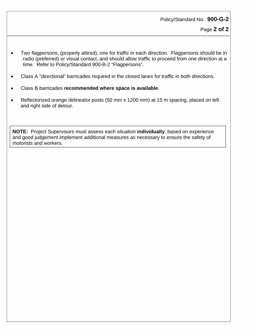
Policy/Standard No. 900-G-2
Page 2 of 2 Two flagpersons, (properly attired), one for traffic in each direction. Flagpersons should be in
radio (preferred) or visual contact, and should allow traffic to proceed from one direction at a time. Refer to Policy/Standard 900-B-2 “Flagpersons”.
Class A "directional" barricades required in the closed lanes for traffic in both directions. Class B barricades recommended where space is available. Reflectorized orange delineator posts (50 mm x 1200 mm) at 15 m spacing, placed on left
and right side of detour. NOTE: Project Supervisors must assess each situation individually; based on experience and good judgement implement additional measures as necessary to ensure the safety of motorists and workers.

Policy/Standard No. 900-H-1
Effective Date:
Traffic Control Device: Work Zone Date of Revision: March 15, 2002 Division: Work Zone Traffic Management - Long Term Subject: Traffic Diversion - Long Term Page 1 of 1 Purpose Protection of the travelling public, and the safety of workers is paramount. However, these must be weighed against the cost and time involved with the installation and removal of the necessary traffic control devices. Long term traffic diversions are required when the nature of work activities extend the disruption of traffic beyond a single day. The traffic diversions are typically designed to a higher level than short term lane closures to limit the manpower required for flagging operations.
Definition Long Term means a traffic diversion that is installed for any period through the hours of darkness.
Policy Whenever a construction and maintenance activity or other situation causes the requirement for a traffic diversion that will extend beyond a single day (i.e. overnight or longer) a special Traffic Management Plan (TMP) must be designed, implemented, and maintained. This policy applies to all Provincial Trunk Highways and Provincial Roads.
Standard Traffic Control should consist of one of the following Traffic Management Plans:
TMP-15 - Left Lane Drop - Four-Lane Divided Highway TMP-16 - Right Lane Drop - Four-Lane Divided Highway
RECOMMENDED: “ORIGINAL SIGNED BY” APPROVED: “ORIGINAL SIGNED BY” Director, Traffic Engineering Executive Director Highway Engineering
Policy/Standard No. 900-H-2
Effective Date: April 15, 1997
Traffic Control Device: Work Zone Date of Revision: March 15, 2002 Division: Subject: Four Lane Divided Highway Page 1 of 2 Conversion to Two-Lane Two-Way (2L2W) Operation Purpose Occasionally it is necessary to operate a four-lane divided highway as a two-lane two-way (2L2W) highway to accommodate construction or maintenance activities, or emergencies. However, these operations can be exceptionally dangerous, particularly over longer stretches of road where there is considerable risk of head-on collisions.
Policy Before implementing any 2L2W operation the use of any adjacent service roads should be considered as an alternate route. Because of the risks associated with 2L2W operation, the opposing traffic flows must be physically separated. The most desirable method of providing this separation is by the use of the portable concrete median barrier (CMB) or water filled plastic median barrier, supplemented by reflective delineators. However, for projects of considerable length, short term projects, or where sufficient clear roadway width is not available (bridge decks, etc.), it may not be practical to utilize CMB's. Under these conditions other devices as noted may be used.
Standard To prohibit passing on the 2L2W section, either flexible, highly visible fluorescent orange reflectorized marker posts at 10 m spacing, or portable concrete or plastic water-filled median barriers should be used to separate opposing traffic flows. These devices should be supplemented by barrier delineators or by a pair of yellow temporary overlay markers (TOM) at 10 m intervals when the orange marker posts are used. When CMB's are used, care must be taken to orient the end units such that the unprotected ends are not exposed to oncoming traffic. RECOMMENDED: “ORIGINAL SIGNED BY” APPROVED: “ORIGINAL SIGNED BY” Director, Traffic Engineering Executive Director Highway Engineering
Policy/Standard No. 900-H-2
Page 2 of 2 Under normal conditions it will be necessary to reduce the prevailing speed limit on the 2L2W section. Refer to Policy/Standard 900-C-6. In addition, speed reductions (advisory or regulatory) may be necessary through the crossover areas. (For an example see drawing TMP-25) At least one set of DO NOT PASS (RB-31) and TWO WAY TRAFFIC (RB-24) signs should be installed. They should be repeated at a minimum interval of 1 km, in each direction when applicable, and following Provincial Trunk Highway or Provincial Road intersections. A minimum clear lane width of 3.7 m including shoulders should normally be maintained at all times. Reduced widths may be approved by the Director of Traffic Engineering. However, special signing, and notification of the Road Information/Permits section will also be required for reduced widths. The 2L2W section should be re-striped with pavement markings of the appropriate colour and configuration. For this purpose either semi-permanent materials or paint may be used. During winter months when 2L2W operations are in effect and markings are obliterated or obscured, every effort must be made to maintain the flexible orange marker posts. All conversions to two-lane two-way operations require approval by Traffic Engineering Branch.
Policy/Standard No. 900-H-4
Effective Date: December 1, 1986
Traffic Control Device: Work Zone Date of Revision: March 15, 2002 Division: Subject: Route Detour Signing Page 1 of 2 Purpose Route detours should always be considered whenever a detour will provide the best service to through (as distinct from local) traffic. It may be necessary or desirable to allow local traffic on the "closed" roadway. In many cases the route that is used to detour highway through traffic is under the jurisdiction of some other authority (municipality, town, local government district). Normally these roads are not used as through routes, particularly to the detour destination. In addition to the basic requirement of safely detouring traffic at the intersection(s) of the detour route and the highway, it is also necessary to provide directional guidance at appropriate intervals, and to control all intersections in a manner that protects the detoured traffic. Route detour notification including all closure information must be given to all affected stakeholders, i.e. rural municipalities, EMS, schools, and R.C.M.P.
Policy/Standard Agreement must be reached between the local traffic authority and the Department regarding the authority to control intersections as required on the detour route. In general, all intersections along a detour route will be controlled with stop signs on either the east/west or north/south approach, favouring the detour route when feasible. If either end of a route detour falls at a location that requires a construction gate assembly as specified in a contract, the gate assembly should be placed or moved so that it does not interfere with or detract from the barricade assemblies or signing required for the route detour. This may require that the construction gate assembly is located a considerable distance upstream from the barricade assembly or signing. Detour highway route marker assemblies should be installed and maintained at all intersections where the detour route changes direction, and at other locations as required to maintain a maximum interval of 2 km between route markers. RECOMMENDED: “ORIGINAL SIGNED BY” APPROVED: “ORIGINAL SIGNED BY” Director, Traffic Engineering Executive Director Highway Engineering
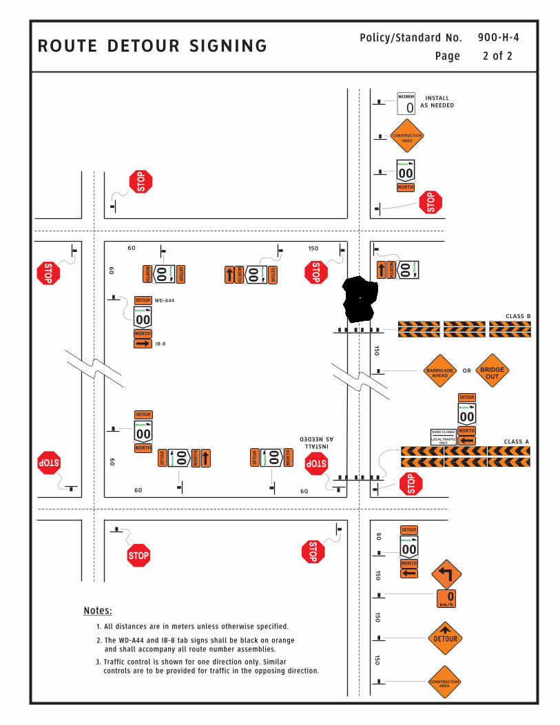
ROUTE DETOUR SIGNINGPolicy/Standard No.
Notes:
1. All distances are in meters unless otherwise specified.
3. Traffic control is shown for one direction only. Similarcontrols are to be provided for traffic in the opposing direction.
2. The WD-A44 and IB-8 tab signs shall be black on orangeand shall accompany all route number assemblies.
Page 2 of 2
900-H-4
ST
OP
ST
OP
ST
OP
STOP STOP
STOP
ST
OP
ST
OP
ST
OP
00
00
00
00
00
00
00
00
00
00
60
60
60
150
150
150
60
60
INSTALL
ASNEEDED
INSTALL
AS NEEDED
150
150
CLASS B
WD-A44
IB-8
CLASS A
OR
60
DETOUR
DETOUR
DE
TO
UR
DE
TO
UR
DETOUR
DETOUR
DE
TO
UR
DE
TO
UR
ROAD CLOSED
LOCAL TRAFFIC
ONLY
CONSTRUCTION
AREA
CONSTRUCTION
ENDS
0
BRIDGE
OUT
BARRICADE
AHEAD
0
Policy/Standard No. 900-H-5
Effective Date: February 25, 1998
Traffic Control Device: Work Zone Date of Revision: March 15, 2002 Division: Temporary Warning Subject: Truck Entrance Page 1 of 2 Purpose Under some conditions it may be necessary or desirable to indicate the location where trucks are entering or crossing the main highway in order to minimize potential conflicts between high speed through traffic and slow moving trucks.
Policy Orange symbolic TRUCK ENTRANCE signs (TC-54R) should be installed when any one of the following warranting conditions is met: An entering truck stopped at the entering roadway stop sign is not visible to approaching traffic
on the main highway from at least the stopping sight distance. See Table 1. Chronic blowing dust or blowing snow on the main highway or haul road restricts the visibility
of trucks to approaching traffic on the main highway. (Dust conditions should be treated where feasible with calcium chloride, water, etc. to alleviate this condition, and the continuance of truck haul operations closely monitored during dusty or snowy conditions to ensure that traffic safety is not compromised.)
Trucks are entering a haul road reserved lane, typically as part of a four-lane divided highway,
which is coned or delineated to separate it from the through traffic lane. Signs are not necessary if trucks do not cross or otherwise conflict with through traffic.
A recorded incidence of entering truck/through traffic conflicts or collisions. Signs in this
instance may be installed only with the approval of the Director of Traffic Engineering.
Note: Where feasible haul road approaches should be located/relocated with consideration to providing maximum approach visibility for highway traffic.
To limit the proliferation of unnecessary signs and to preserve the impact of necessary signs, TRUCK ENTRANCE signs should only be installed where and when strictly warranted. RECOMMENDED: “ORIGINAL SIGNED BY” APPROVED: “ORIGINAL SIGNED BY” Director, Traffic Engineering Executive Director Highway Engineering
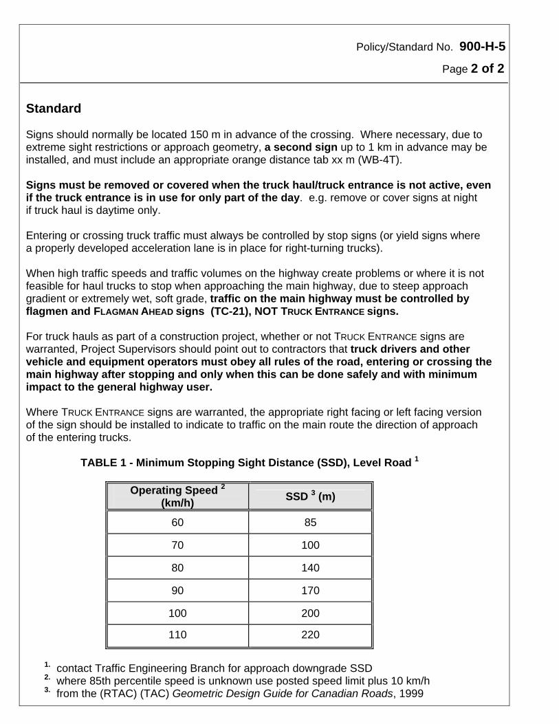
Policy/Standard No. 900-H-5
Page 2 of 2 Standard Signs should normally be located 150 m in advance of the crossing. Where necessary, due to extreme sight restrictions or approach geometry, a second sign up to 1 km in advance may be installed, and must include an appropriate orange distance tab xx m (WB-4T). Signs must be removed or covered when the truck haul/truck entrance is not active, even if the truck entrance is in use for only part of the day. e.g. remove or cover signs at night if truck haul is daytime only. Entering or crossing truck traffic must always be controlled by stop signs (or yield signs where a properly developed acceleration lane is in place for right-turning trucks). When high traffic speeds and traffic volumes on the highway create problems or where it is not feasible for haul trucks to stop when approaching the main highway, due to steep approach gradient or extremely wet, soft grade, traffic on the main highway must be controlled by flagmen and FLAGMAN AHEAD signs (TC-21), NOT TRUCK ENTRANCE signs. For truck hauls as part of a construction project, whether or not TRUCK ENTRANCE signs are warranted, Project Supervisors should point out to contractors that truck drivers and other vehicle and equipment operators must obey all rules of the road, entering or crossing the main highway after stopping and only when this can be done safely and with minimum impact to the general highway user. Where TRUCK ENTRANCE signs are warranted, the appropriate right facing or left facing version of the sign should be installed to indicate to traffic on the main route the direction of approach of the entering trucks. TABLE 1 - Minimum Stopping Sight Distance (SSD), Level Road 1
Operating Speed 2 (km/h)
SSD 3 (m)
60 85
70 100
80 140
90 170
100 200
110 220
1. contact Traffic Engineering Branch for approach downgrade SSD 2. where 85th percentile speed is unknown use posted speed limit plus 10 km/h 3. from the (RTAC) (TAC) Geometric Design Guide for Canadian Roads, 1999
Policy/Standard No. 900-H-6
Effective Date: March 1, 1999
Traffic Control Device: Work Zone Date of Revision: March 15, 2002 Division: Temporary Warning Subject: Traffic Control at New 4-Lane Divided Highways (Signing and Marking of Major Intersections) Page 1 of 2 Purpose To limit the probability of wrong way movements on newly opened rural sections of 4-lane divided highways by enhancing some intersection traffic controls.
Policy Intersection Traffic Controls on newly opened sections of rural 4-lane divided highways should be enhanced for a short time following opening of the new facility. This should include all PTH, PR, and higher volume (500 + AADT) municipal road intersections.
Standard Two temporary, yellow symbolic DIVIDED HIGHWAY AHEAD warning signs (WA-34) with verbal
DIVIDED HIGHWAY tabs should be installed, where feasible, at approximately 200 in advance of the stop sign for a minimum three month period. These signs should be enhanced by permanent reflectorized fluorescent orange metal flags.
Temporary pavement arrows should be placed at the throat of the intersection. Pavement lane lines should be extended as far as possible into the intersection. Permanent WRONG-WAY signs should be enhanced by the installation of temporary
reflectorized fluorescent orange metal flags, which should be removed after a three month period. These flags should not remain permanently but may be retained for up to 6 months depending on the continued occurrence of wrong-way movements.
Continuous flagging operations at primary intersections should be provided for the first 24 to
48 hours following opening, and daytime flagging for the next 2 days, extended or reduced depending on the incidence of observed wrong-way movements, entering traffic volumes, and the nature of the entering traffic (local, commuter, recreational, long distance, etc.).
All standard 4-lane intersection signing should be in place. Refer to Policy Standard 100-C-12
for wrong way signing policy, and to Section SA-8 of the Traffic Signing Manual for wrong way signing installation details.
RECOMMENDED: “ORIGINAL SIGNED BY” APPROVED: “ORIGINAL SIGNED BY” Director, Traffic Engineering Executive Director Highway Engineering
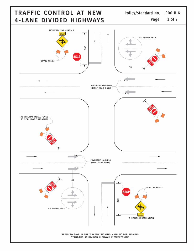
TRAFFIC CONTROL AT NEW
4-LANE DIVIDED HIGHWAYS
Policy/Standard No.
Page 2 of 2
900-H-6
STOPSTOP
200
200
METALFLAGS
METAL FLAGS
PAVEMENT MARKING
(FIRST YEAR ONLY)
ADDITIONAL METAL FLAGS
TYPICAL (FOR 3 MONTHS)
PAVEMENT MARKING
(FIRST YEAR ONLY)
OR
OR
AS APPLICABLE
AS APPLICABLE
3MONTHINSTALLATION
3 MONTH INSTALLATION
REFER TO SA-8 IN THE ‘TRAFFIC SIGNING MANUAL’ FOR SIGNING
STANDARD AT DIVIDED HIGHWAY INTERSECTIONS
WRO
NG
WAY
WRO
NG
WAY
WRO
NG
WAY
WRO
NG
WAY
DIVIDED
HIGHWAY
DIVIDED
HIGHWAY
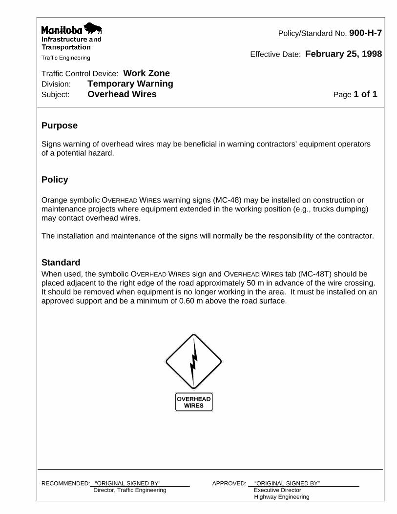
Policy/Standard No. 900-H-7
Effective Date: February 25, 1998
Traffic Control Device: Work Zone Division: Temporary Warning Subject: Overhead Wires Page 1 of 1 Purpose Signs warning of overhead wires may be beneficial in warning contractors’ equipment operators of a potential hazard.
Policy Orange symbolic OVERHEAD WIRES warning signs (MC-48) may be installed on construction or maintenance projects where equipment extended in the working position (e.g., trucks dumping) may contact overhead wires. The installation and maintenance of the signs will normally be the responsibility of the contractor.
Standard When used, the symbolic OVERHEAD WIRES sign and OVERHEAD WIRES tab (MC-48T) should be placed adjacent to the right edge of the road approximately 50 m in advance of the wire crossing. It should be removed when equipment is no longer working in the area. It must be installed on an approved support and be a minimum of 0.60 m above the road surface.
RECOMMENDED: “ORIGINAL SIGNED BY” APPROVED: “ORIGINAL SIGNED BY” Director, Traffic Engineering Executive Director Highway Engineering
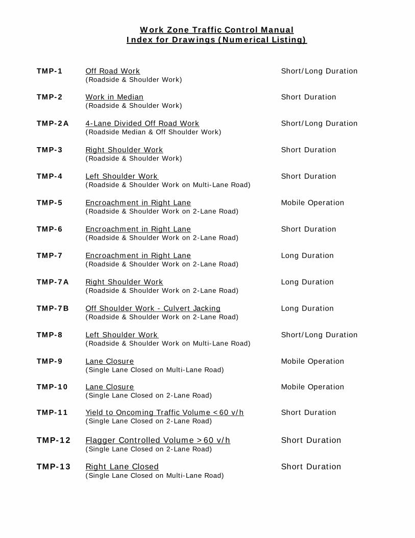
Work Zone Traffic Control Manual Index for Drawings (Numerical Listing)
TMP-1 Off Road Work Short/Long Duration (Roadside & Shoulder Work)
TMP-2 Work in Median Short Duration (Roadside & Shoulder Work) TMP-2A 4-Lane Divided Off Road Work Short/Long Duration (Roadside Median & Off Shoulder Work) TMP-3 Right Shoulder Work Short Duration (Roadside & Shoulder Work) TMP-4 Left Shoulder Work Short Duration (Roadside & Shoulder Work on Multi-Lane Road) TMP-5 Encroachment in Right Lane Mobile Operation (Roadside & Shoulder Work on 2-Lane Road) TMP-6 Encroachment in Right Lane Short Duration (Roadside & Shoulder Work on 2-Lane Road) TMP-7 Encroachment in Right Lane Long Duration (Roadside & Shoulder Work on 2-Lane Road) TMP-7A Right Shoulder Work Long Duration (Roadside & Shoulder Work on 2-Lane Road) TMP-7B Off Shoulder Work - Culvert Jacking Long Duration (Roadside & Shoulder Work on 2-Lane Road) TMP-8 Left Shoulder Work Short/Long Duration (Roadside & Shoulder Work on Multi-Lane Road) TMP-9 Lane Closure Mobile Operation (Single Lane Closed on Multi-Lane Road) TMP-10 Lane Closure Mobile Operation (Single Lane Closed on 2-Lane Road) TMP-11 Yield to Oncoming Traffic Volume <60 v/h Short Duration (Single Lane Closed on 2-Lane Road) TMP-12 Flagger Controlled Volume >60 v/h Short Duration (Single Lane Closed on 2-Lane Road) TMP-13 Right Lane Closed Short Duration (Single Lane Closed on Multi-Lane Road)
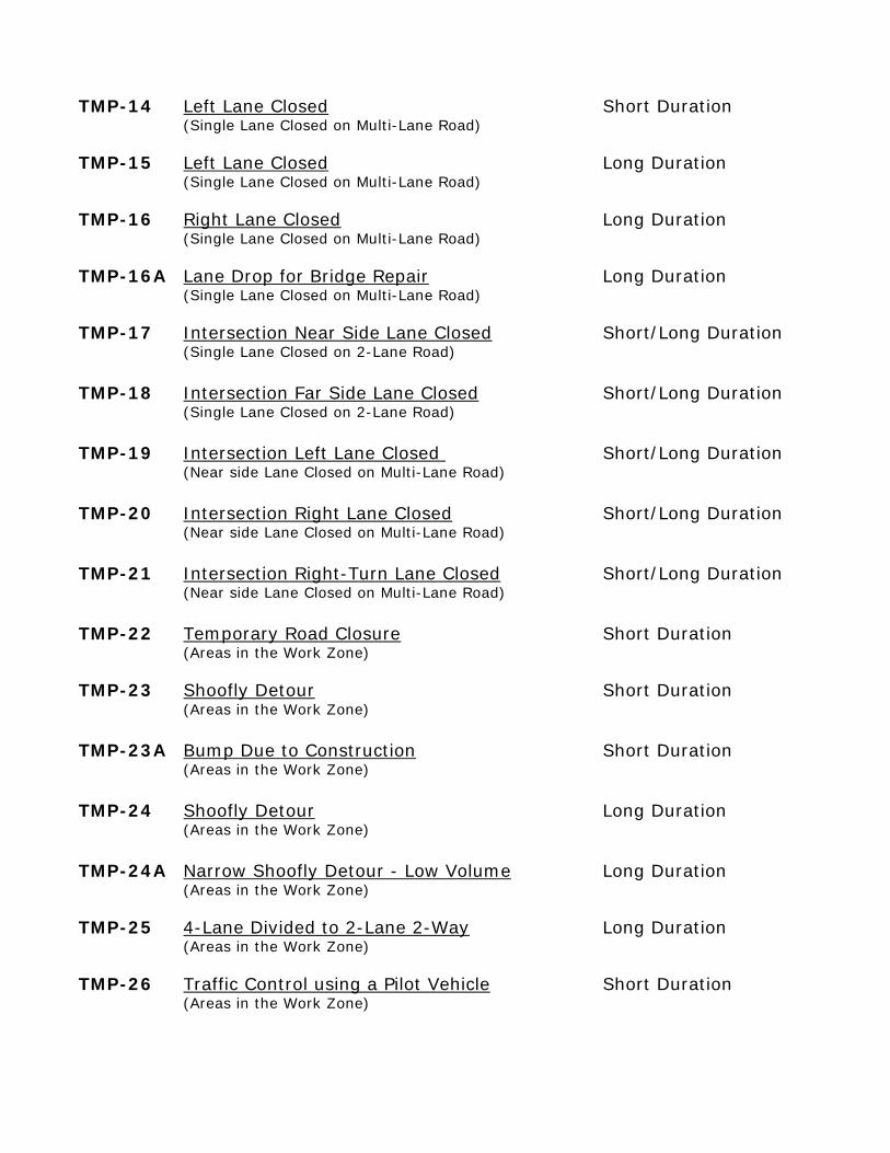
TMP-14 Left Lane Closed Short Duration (Single Lane Closed on Multi-Lane Road) TMP-15 Left Lane Closed Long Duration (Single Lane Closed on Multi-Lane Road) TMP-16 Right Lane Closed Long Duration (Single Lane Closed on Multi-Lane Road) TMP-16A Lane Drop for Bridge Repair Long Duration (Single Lane Closed on Multi-Lane Road) TMP-17 Intersection Near Side Lane Closed Short/Long Duration (Single Lane Closed on 2-Lane Road) TMP-18 Intersection Far Side Lane Closed Short/Long Duration (Single Lane Closed on 2-Lane Road) TMP-19 Intersection Left Lane Closed Short/Long Duration (Near side Lane Closed on Multi-Lane Road) TMP-20 Intersection Right Lane Closed Short/Long Duration (Near side Lane Closed on Multi-Lane Road) TMP-21 Intersection Right-Turn Lane Closed Short/Long Duration (Near side Lane Closed on Multi-Lane Road) TMP-22 Temporary Road Closure Short Duration (Areas in the Work Zone) TMP-23 Shoofly Detour Short Duration (Areas in the Work Zone) TMP-23A Bump Due to Construction Short Duration (Areas in the Work Zone) TMP-24 Shoofly Detour Long Duration (Areas in the Work Zone) TMP-24A Narrow Shoofly Detour - Low Volume Long Duration (Areas in the Work Zone) TMP-25 4-Lane Divided to 2-Lane 2-Way Long Duration (Areas in the Work Zone) TMP-26 Traffic Control using a Pilot Vehicle Short Duration (Areas in the Work Zone)
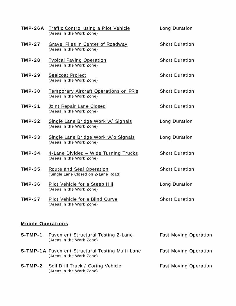
TMP-26A Traffic Control using a Pilot Vehicle Long Duration (Areas in the Work Zone) TMP-27 Gravel Piles in Center of Roadway Short Duration (Areas in the Work Zone) TMP-28 Typical Paving Operation Short Duration (Areas in the Work Zone) TMP-29 Sealcoat Project Short Duration (Areas in the Work Zone) TMP-30 Temporary Aircraft Operations on PR’s Short Duration (Areas in the Work Zone) TMP-31 Joint Repair Lane Closed Short Duration (Areas in the Work Zone) TMP-32 Single Lane Bridge Work w/ Signals Long Duration (Areas in the Work Zone) TMP-33 Single Lane Bridge Work w/o Signals Long Duration (Areas in the Work Zone) TMP-34 4-Lane Divided – Wide Turning Trucks Short Duration (Areas in the Work Zone) TMP-35 Route and Seal Operation Short Duration (Single Lane Closed on 2-Lane Road) TMP-36 Pilot Vehicle for a Steep Hill Long Duration (Areas in the Work Zone) TMP-37 Pilot Vehicle for a Blind Curve Short Duration (Areas in the Work Zone) Mobile Operations S-TMP-1 Pavement Structural Testing 2-Lane Fast Moving Operation (Areas in the Work Zone) S-TMP-1A Pavement Structural Testing Multi-Lane Fast Moving Operation (Areas in the Work Zone) S-TMP-2 Soil Drill Truck / Coring Vehicle Fast Moving Operation (Areas in the Work Zone)
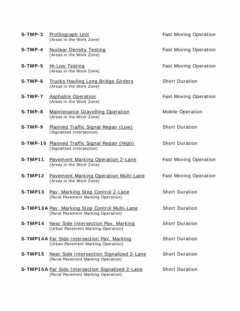
S-TMP-3 Profilograph Unit Fast Moving Operation (Areas in the Work Zone) S-TMP-4 Nuclear Density Testing Fast Moving Operation (Areas in the Work Zone) S-TMP-5 Hi-Low Testing Fast Moving Operation (Areas in the Work Zone) S-TMP-6 Trucks Hauling Long Bridge Girders Short Duration (Areas in the Work Zone) S-TMP-7 Asphalite Operation Fast Moving Operation (Areas in the Work Zone) S-TMP-8 Maintenance Gravelling Operation Mobile Operation (Areas in the Work Zone) S-TMP-9 Planned Traffic Signal Repair (Low) Short Duration (Signalized Intersection) S-TMP-10 Planned Traffic Signal Repair (High) Short Duration (Signalized Intersection) S-TMP11 Pavement Marking Operation 2-Lane Fast Moving Operation (Areas in the Work Zone) S-TMP12 Pavement Marking Operation Multi-Lane Fast Moving Operation (Areas in the Work Zone) S-TMP13 Pav. Marking Stop Control 2-Lane Short Duration (Rural Pavement Marking Operation) S-TMP13A Pav. Marking Stop Control Multi-Lane Short Duration (Rural Pavement Marking Operation) S-TMP14 Near Side Intersection Pav. Marking Short Duration (Urban Pavement Marking Operation) S-TMP14A Far Side Intersection Pav. Marking Short Duration (Urban Pavement Marking Operation) S-TMP15 Near Side Intersection Signalized 2-Lane Short Duration (Rural Pavement Marking Operation) S-TMP15A Far Side Intersection Signalized 2-Lane Short Duration (Rural Pavement Marking Operation)
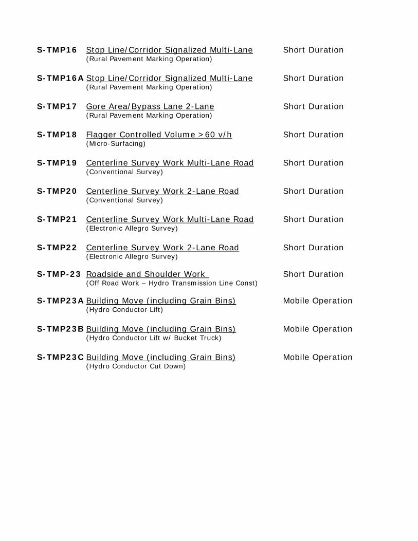
S-TMP16 Stop Line/Corridor Signalized Multi-Lane Short Duration (Rural Pavement Marking Operation) S-TMP16A Stop Line/Corridor Signalized Multi-Lane Short Duration (Rural Pavement Marking Operation) S-TMP17 Gore Area/Bypass Lane 2-Lane Short Duration (Rural Pavement Marking Operation) S-TMP18 Flagger Controlled Volume >60 v/h Short Duration (Micro-Surfacing) S-TMP19 Centerline Survey Work Multi-Lane Road Short Duration (Conventional Survey) S-TMP20 Centerline Survey Work 2-Lane Road Short Duration (Conventional Survey) S-TMP21 Centerline Survey Work Multi-Lane Road Short Duration (Electronic Allegro Survey) S-TMP22 Centerline Survey Work 2-Lane Road Short Duration (Electronic Allegro Survey) S-TMP-23 Roadside and Shoulder Work Short Duration (Off Road Work – Hydro Transmission Line Const) S-TMP23A Building Move (including Grain Bins) Mobile Operation (Hydro Conductor Lift) S-TMP23B Building Move (including Grain Bins) Mobile Operation (Hydro Conductor Lift w/ Bucket Truck) S-TMP23C Building Move (including Grain Bins) Mobile Operation (Hydro Conductor Cut Down)
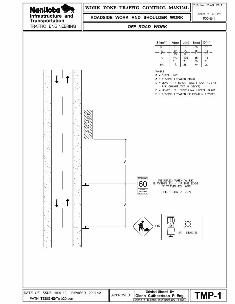
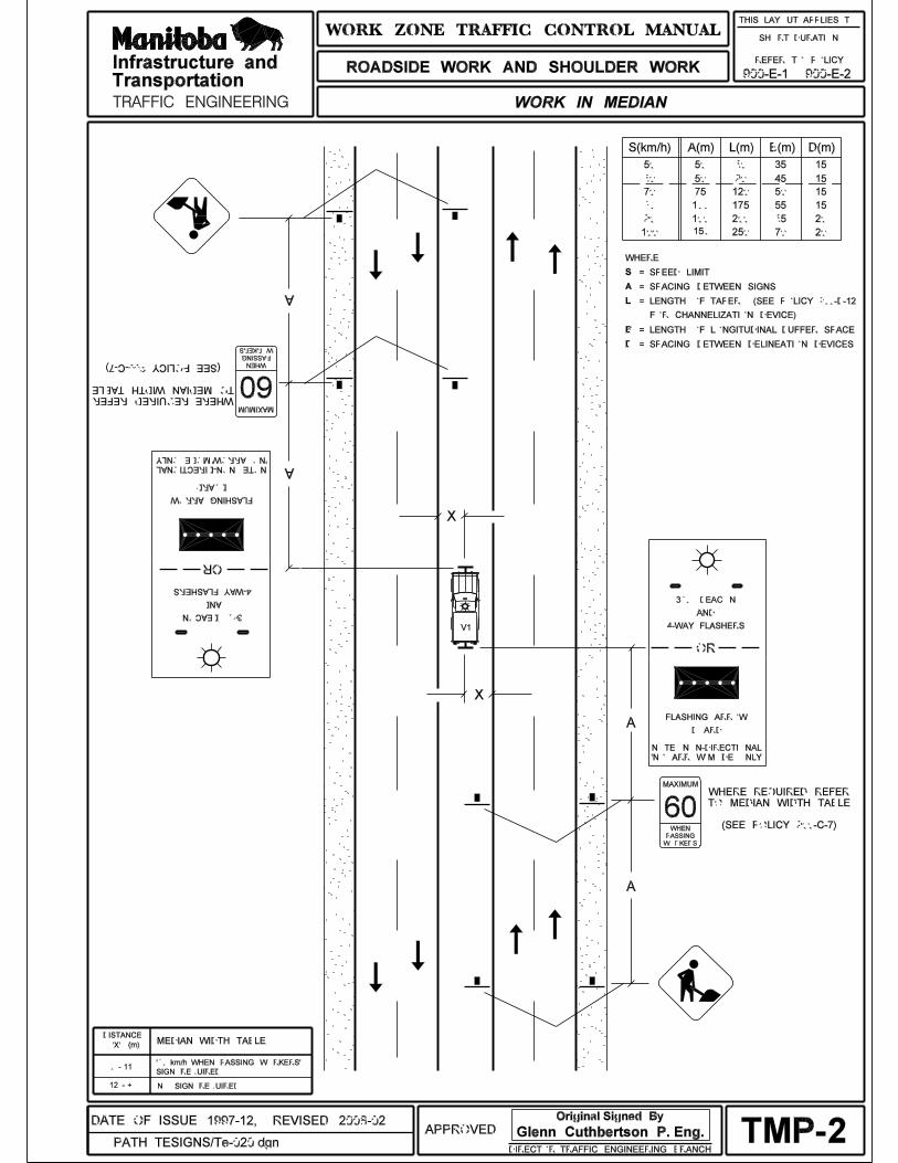
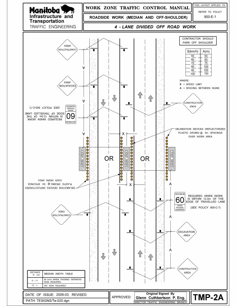
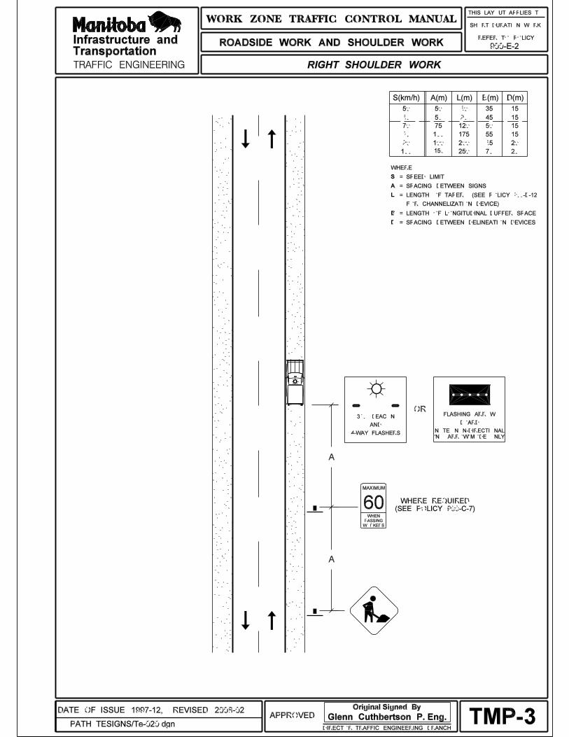
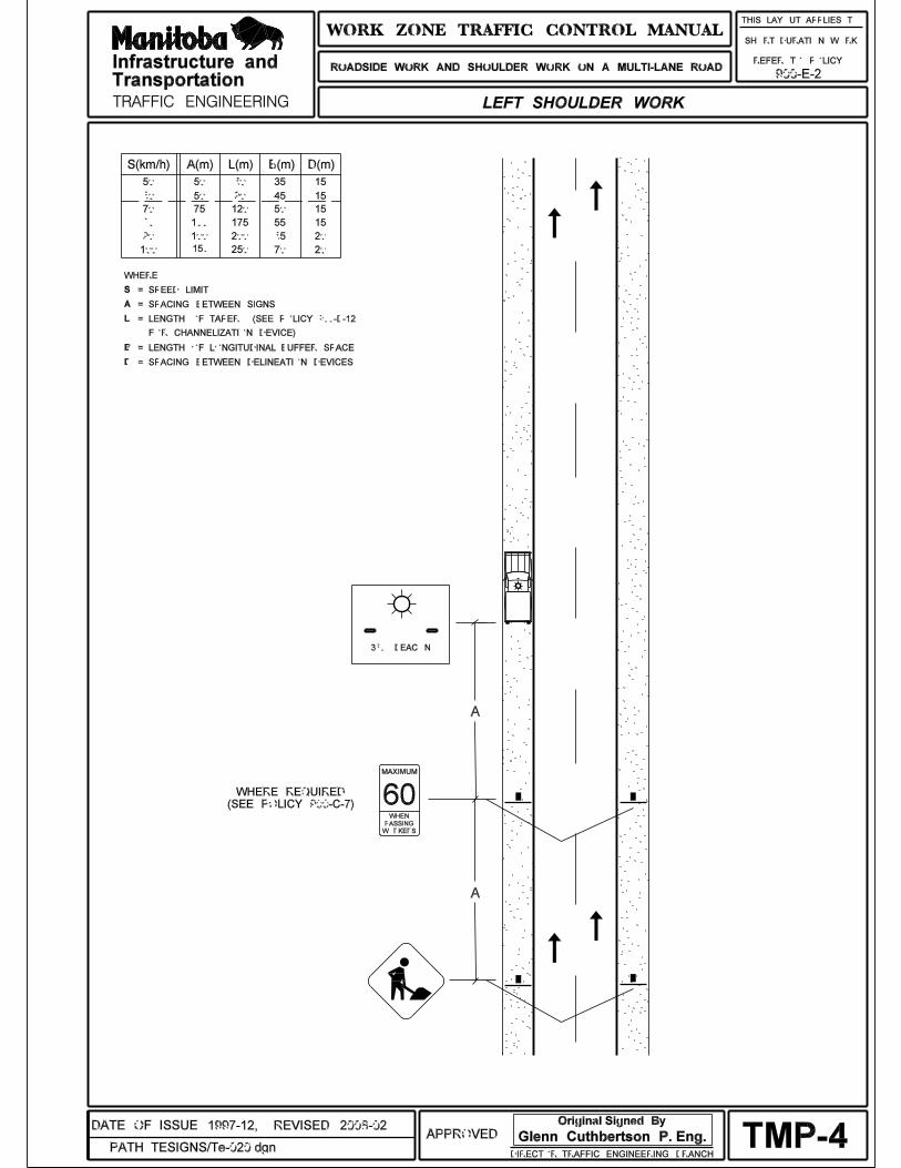
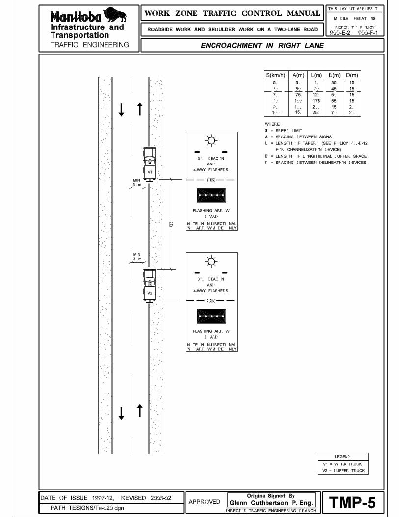
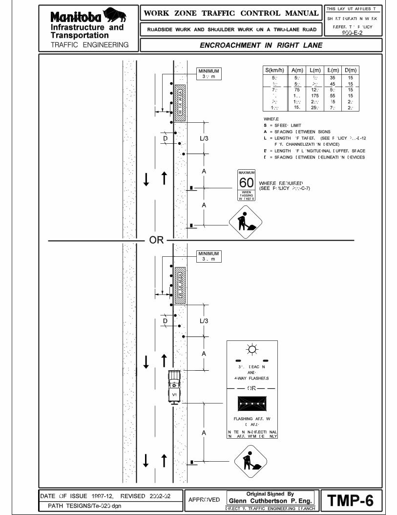
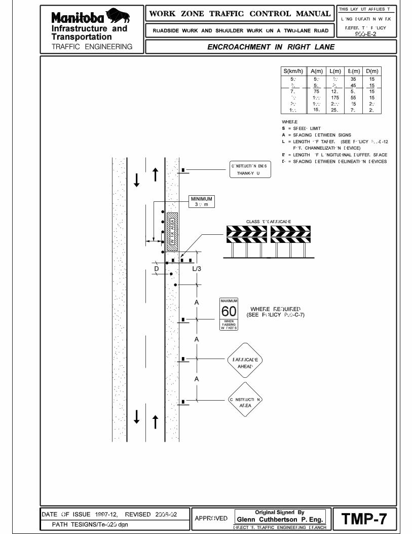
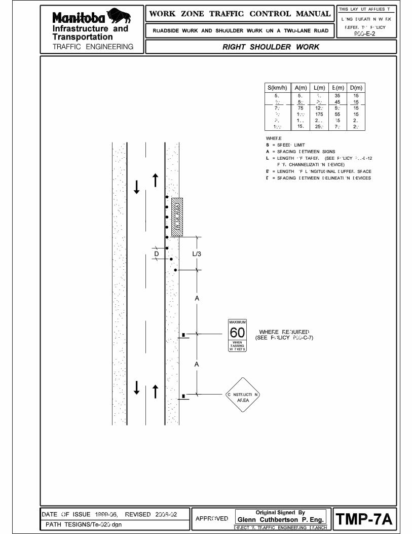
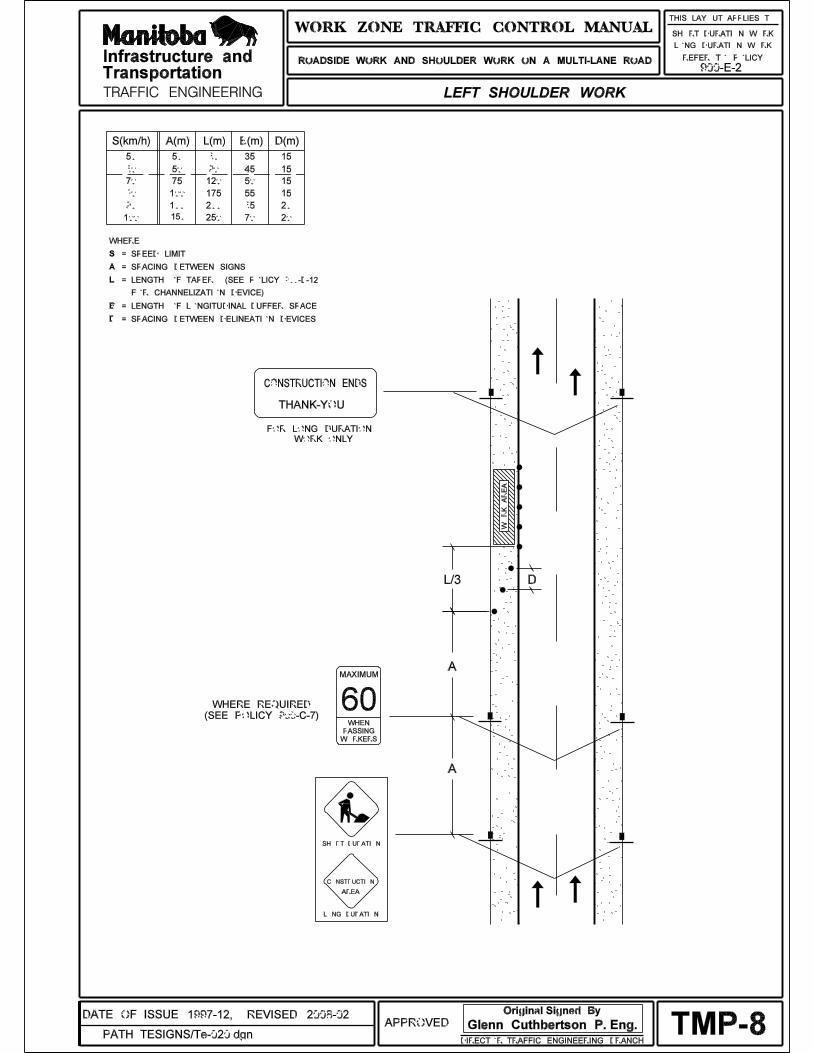
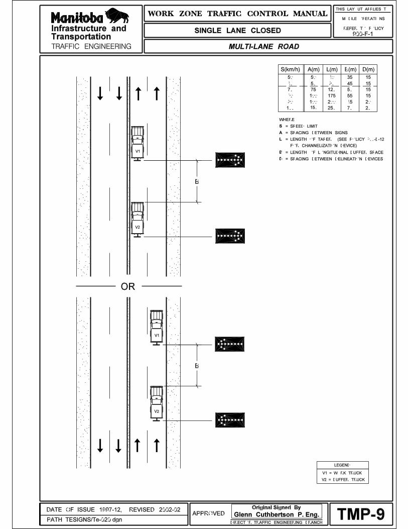
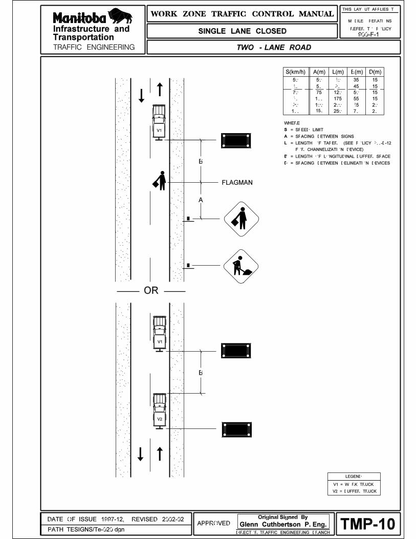
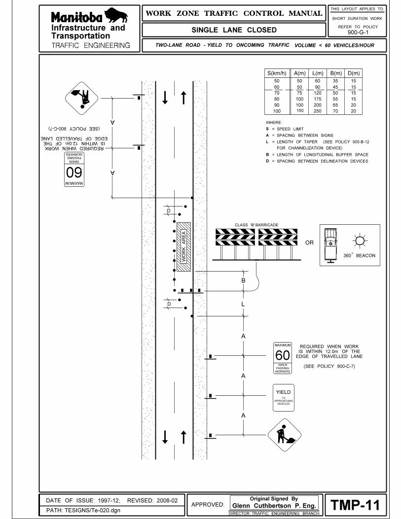
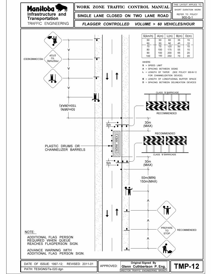
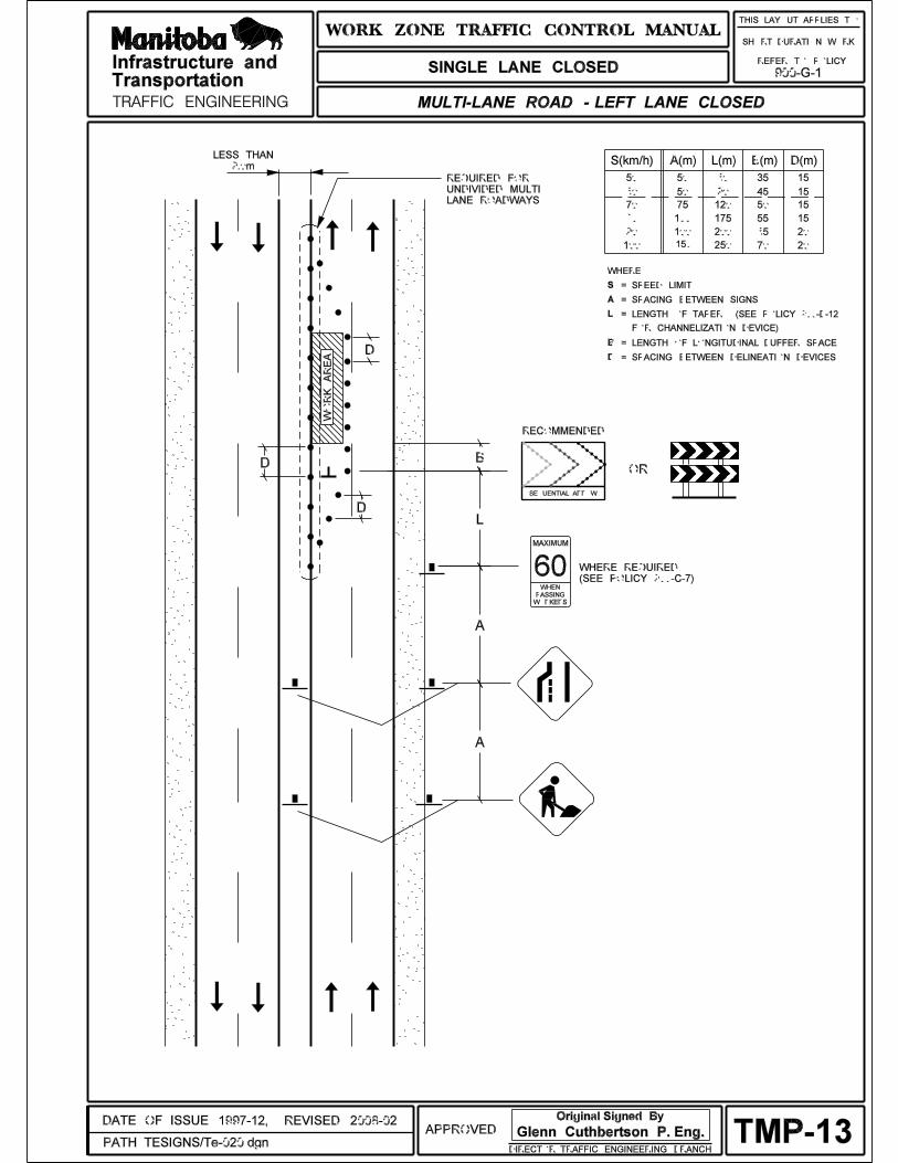
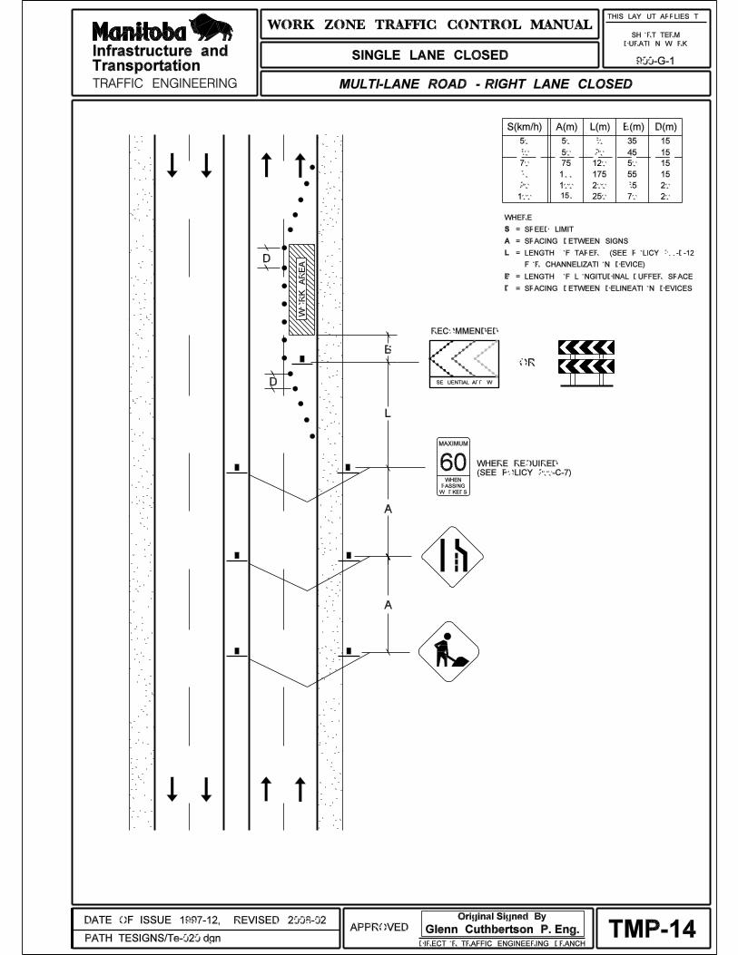
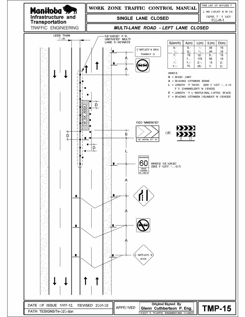
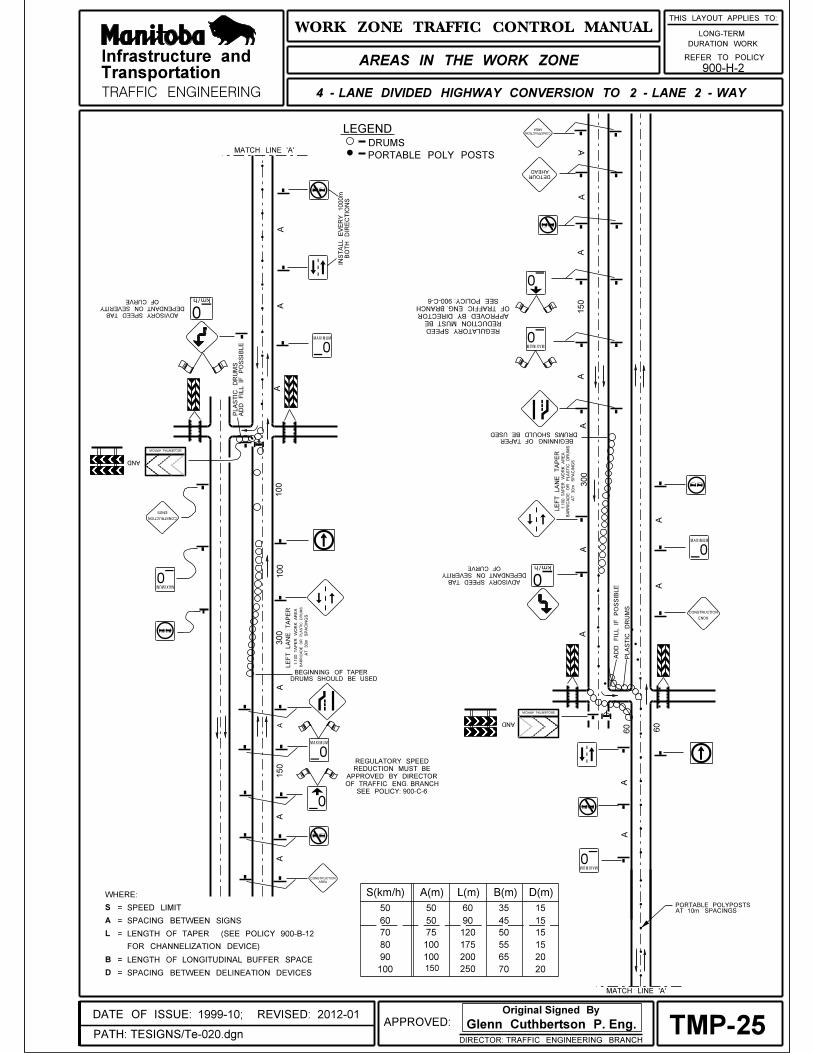
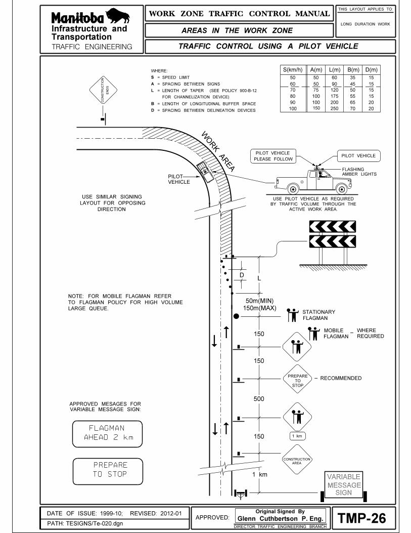
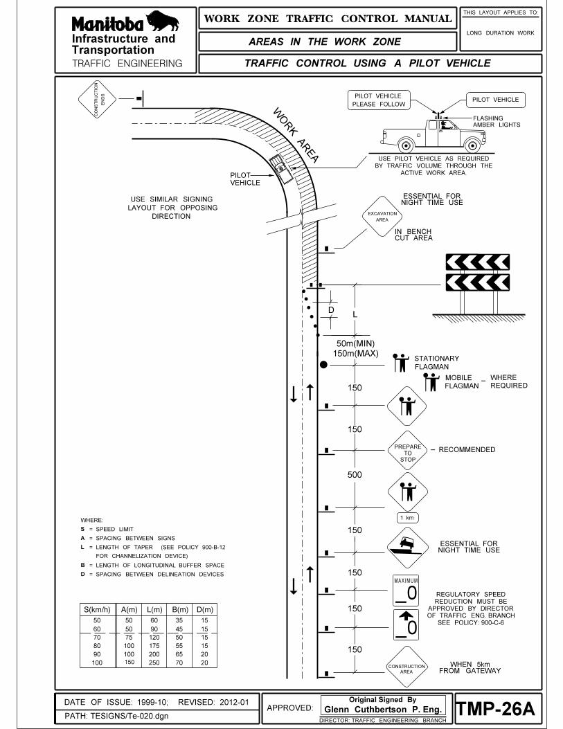
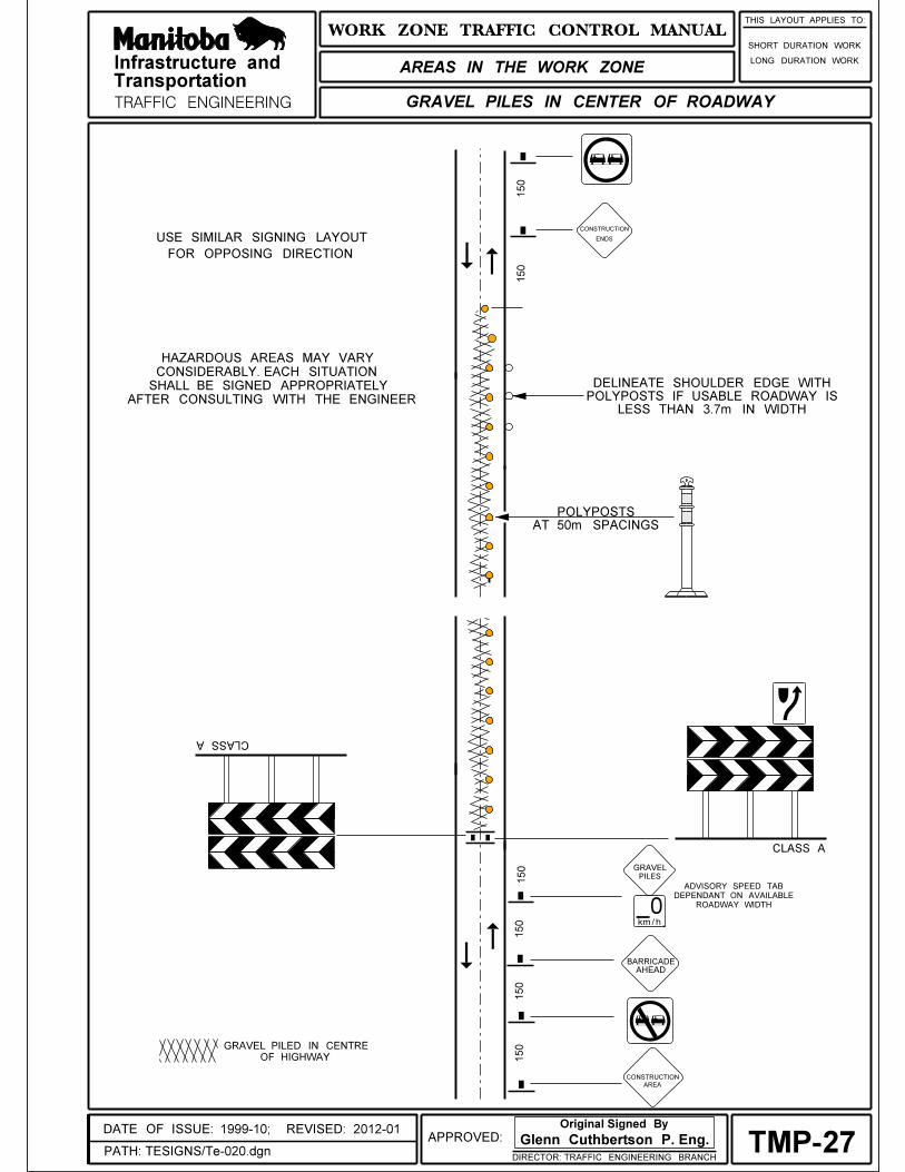
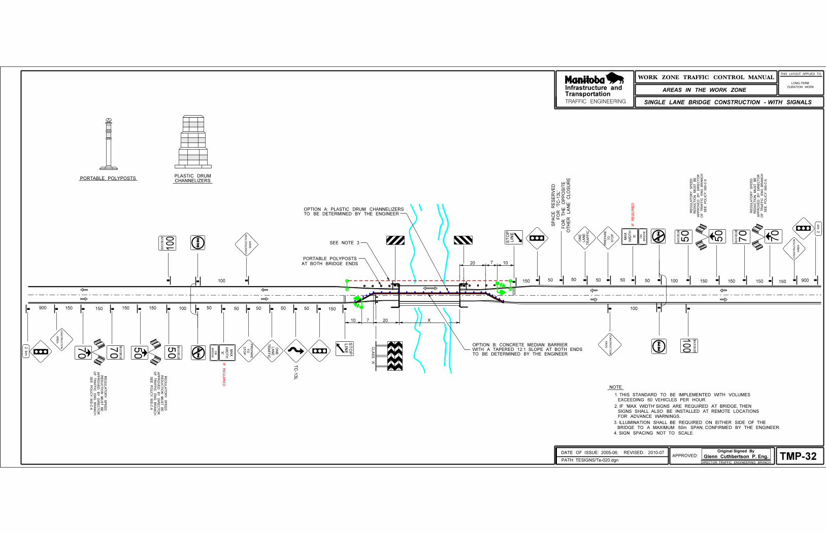
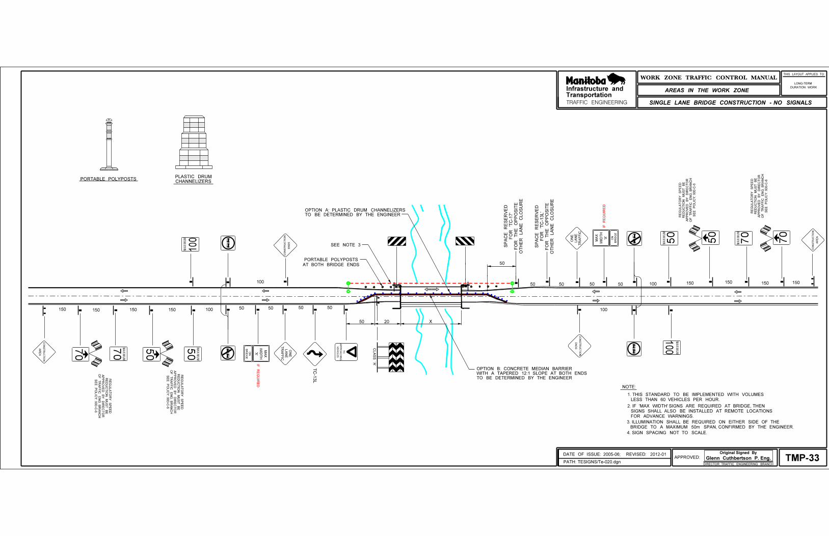
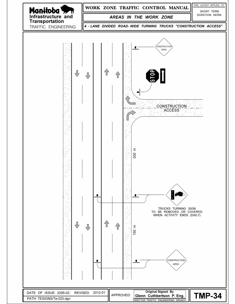
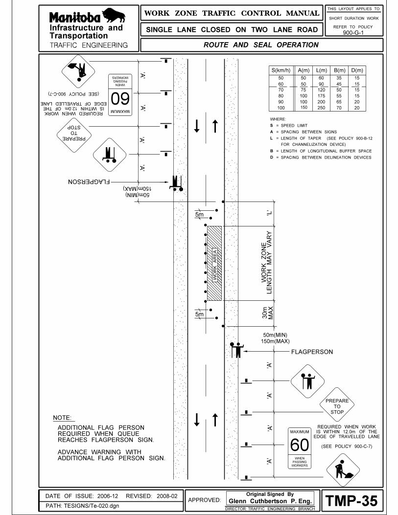
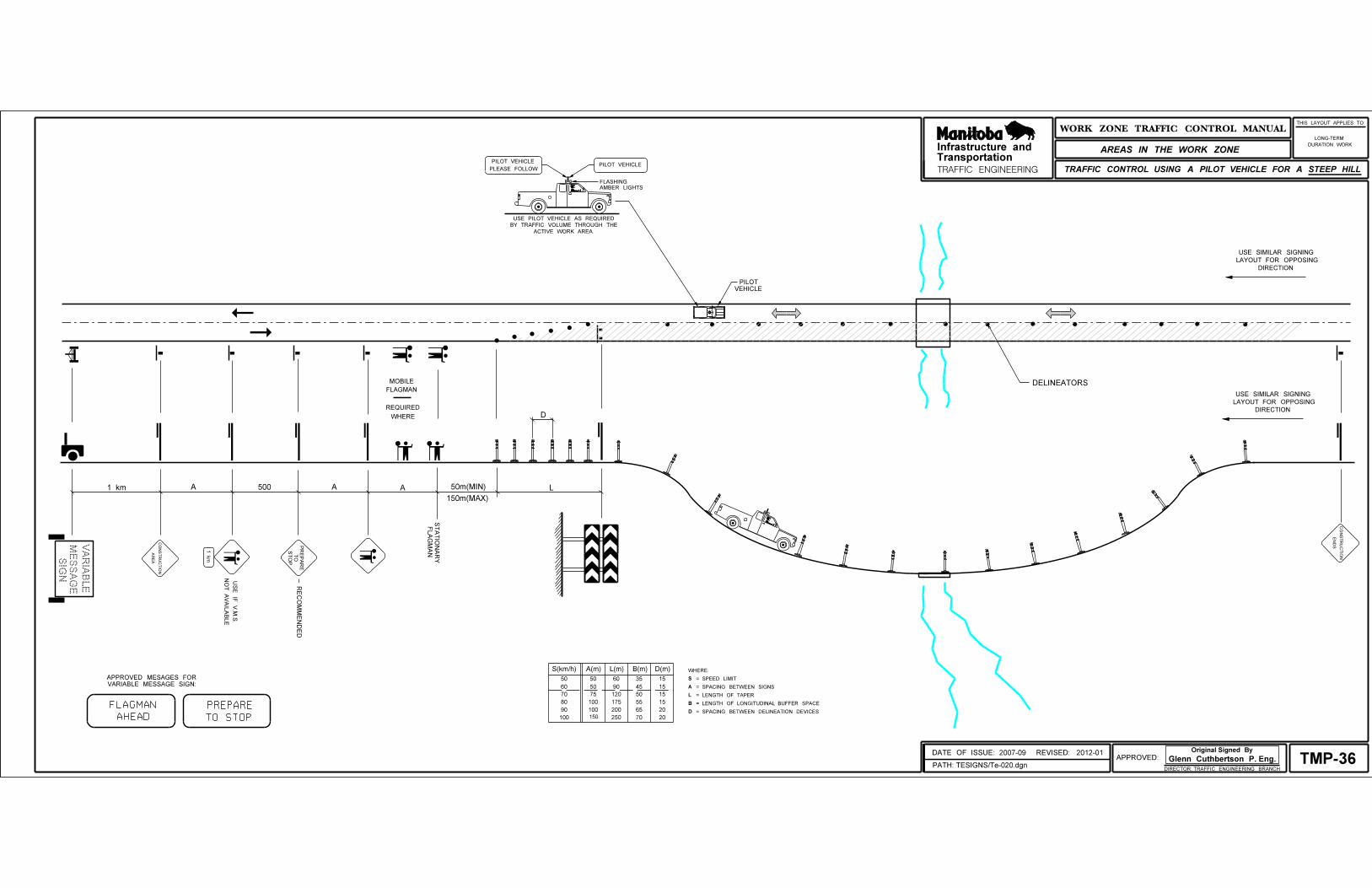
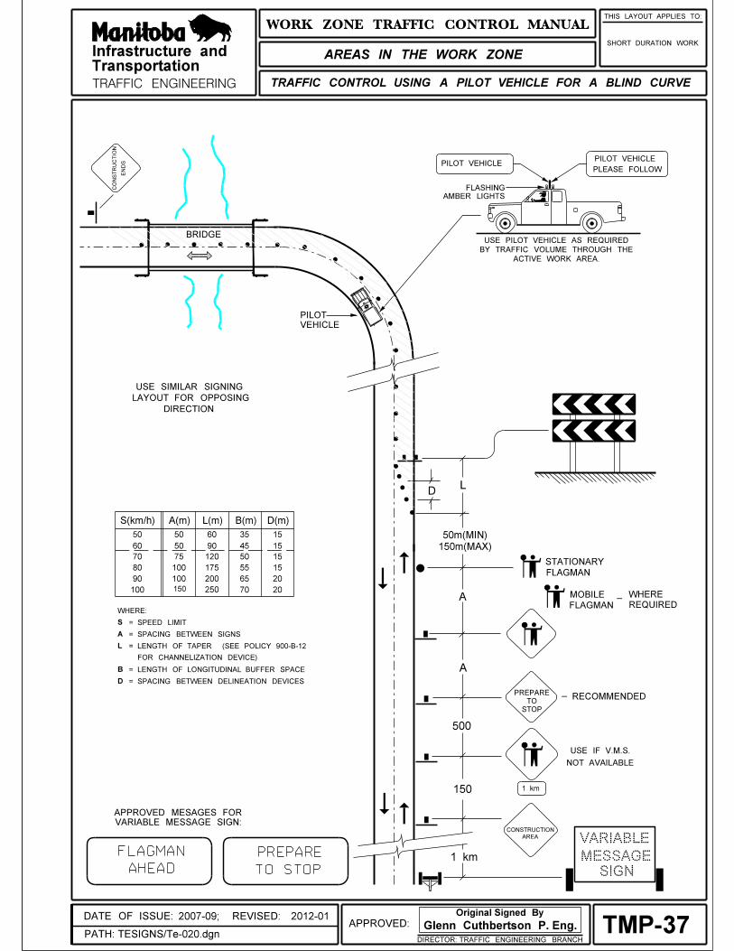
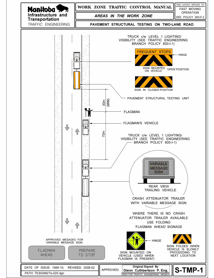
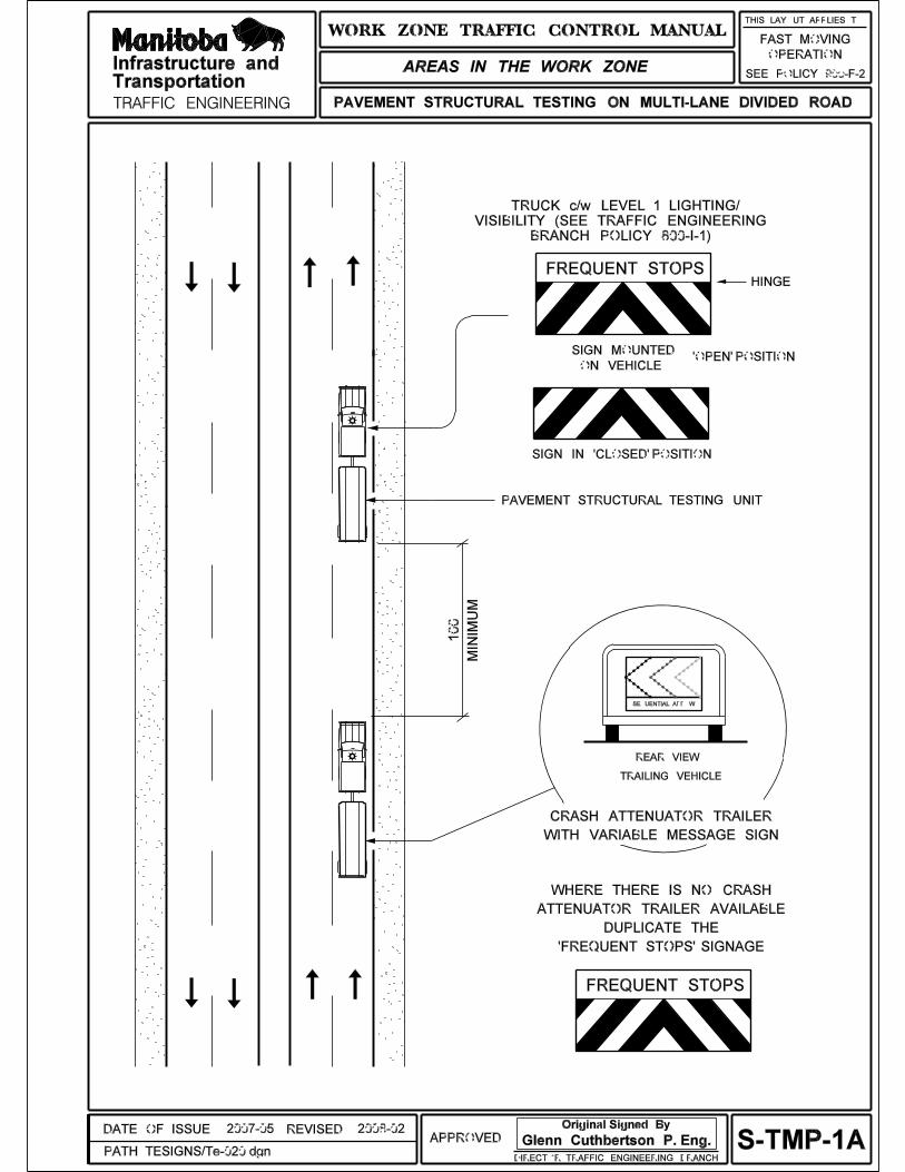
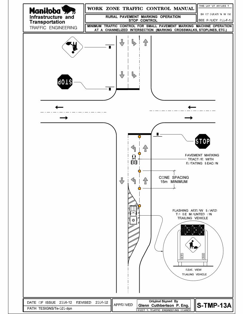
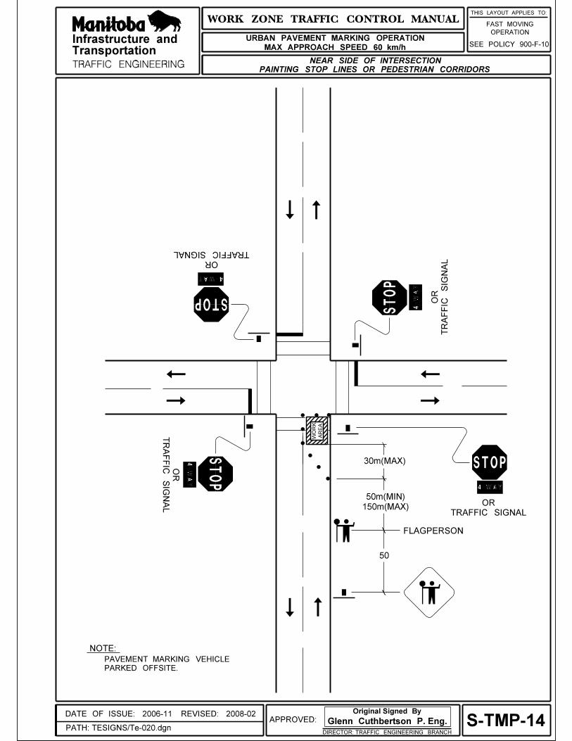
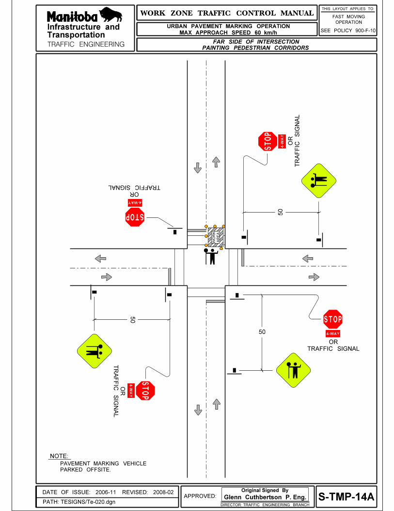
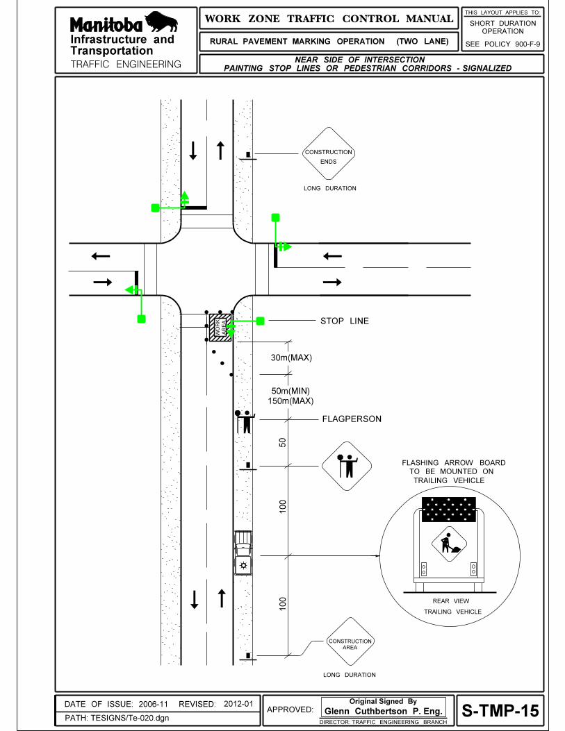
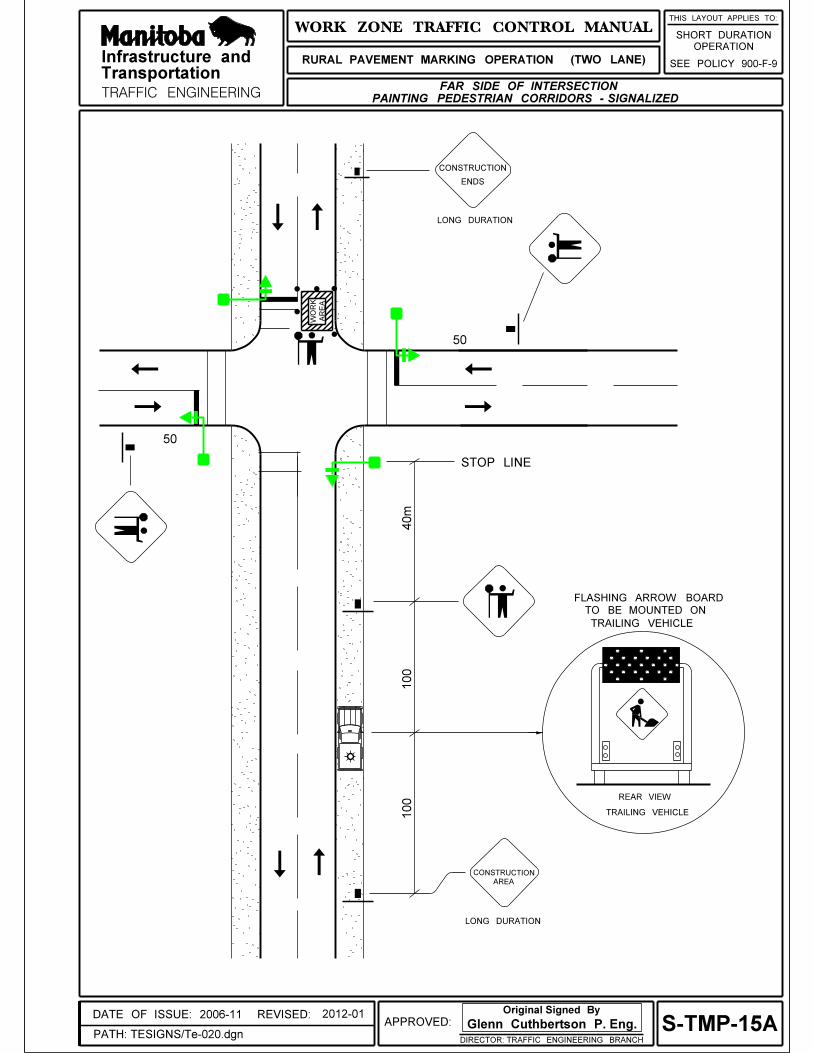
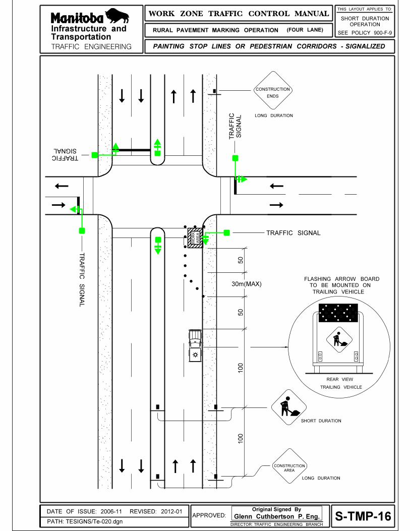
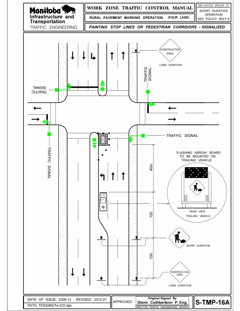
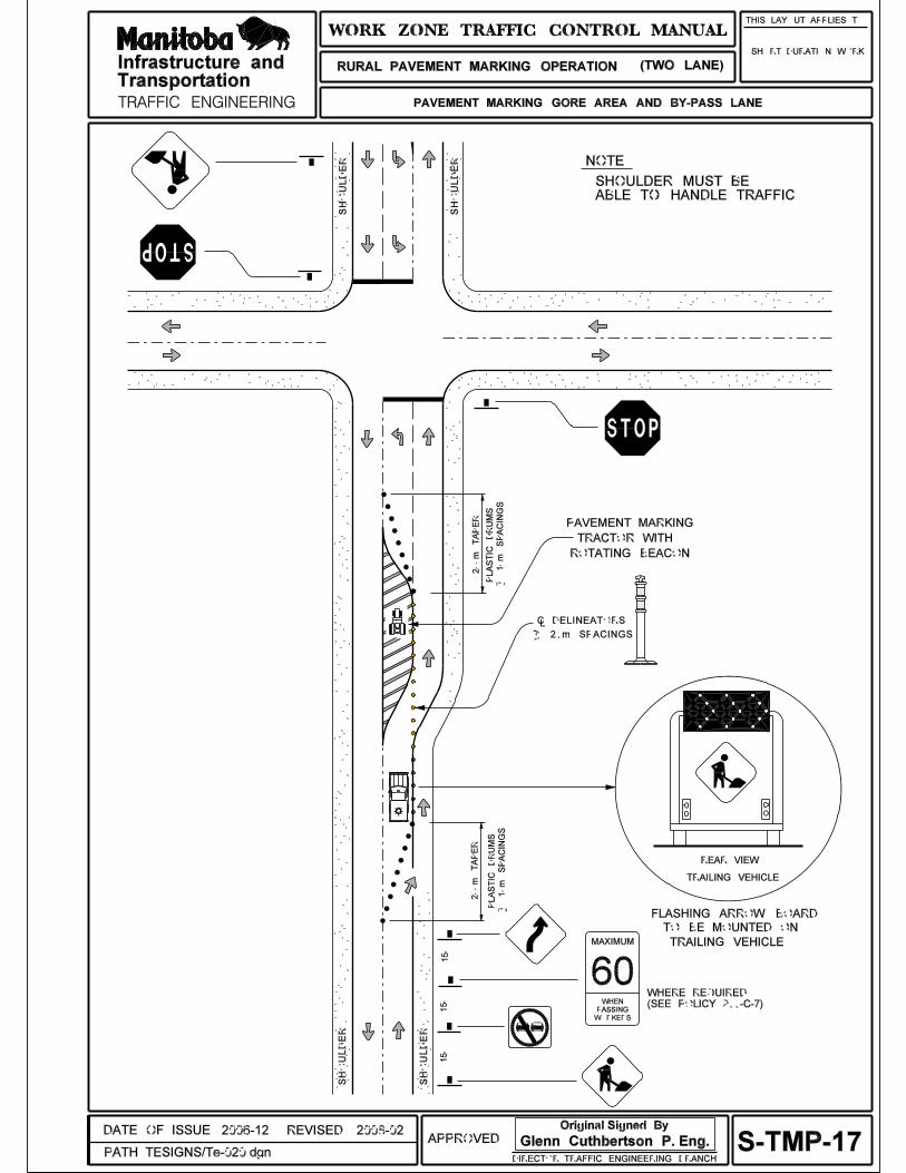
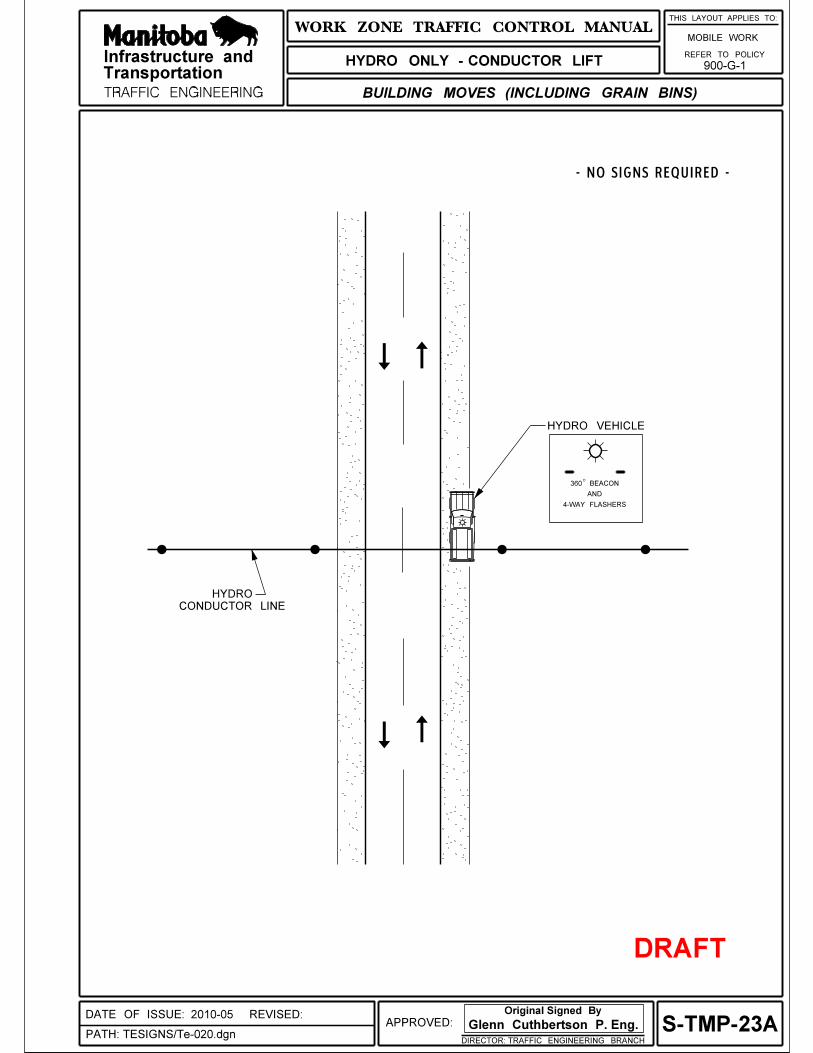
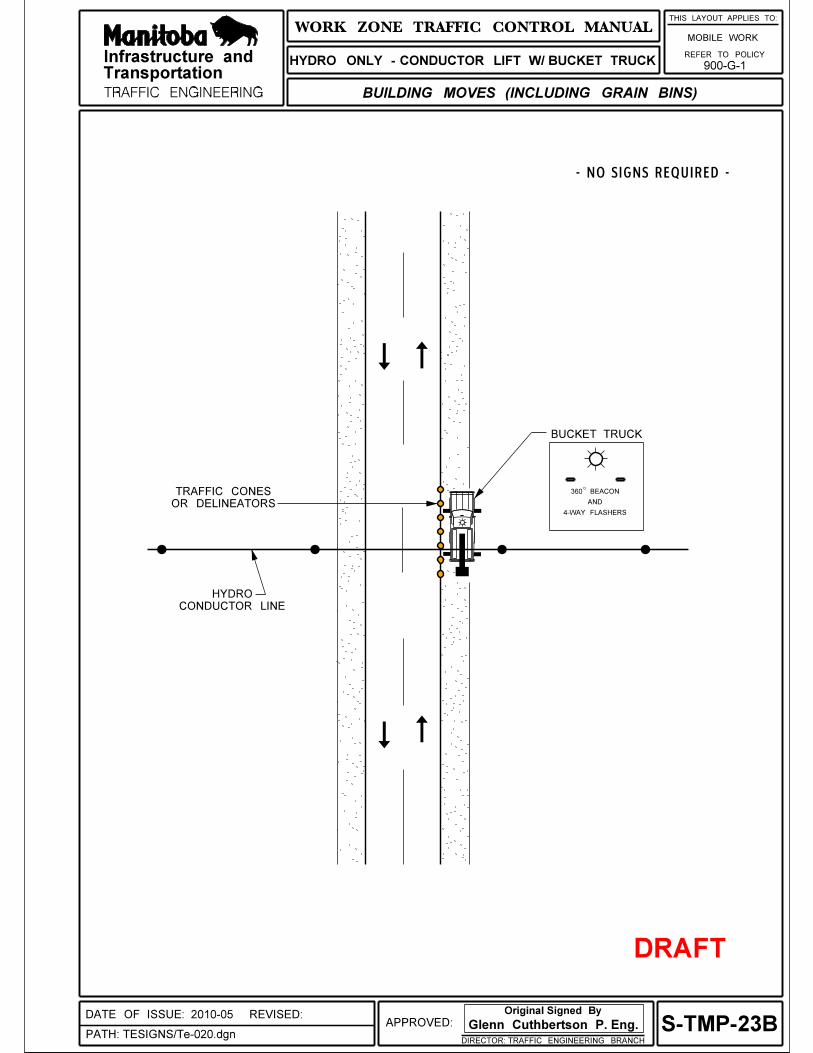
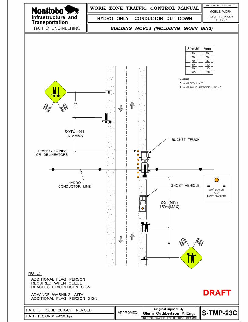
and
Provincial Trunk Highways
Provincial Roads
WORK ZONE
TRAFFIC SIGN SCHEDULE
2010
Infrastructure andTransportation
Traffic Engineering
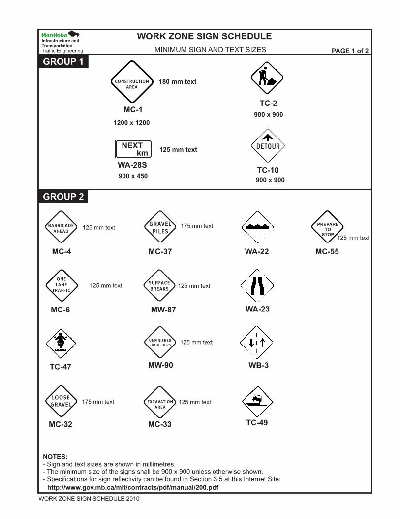
GROUP 1
GROUP 2
NOTES:- Sign and text sizes are shown in millimetres.- The minimum size of the signs shall be 900 x 900 unless otherwise shown.- Specifications for sign reflectivity can be found in Section 3.5 at this Internet Site:
125 mm text
125 mm text125 mm text
125 mm text
125 mm text175 mm text
125 mm text
175 mm text
MINIMUM SIGN AND TEXT SIZES
PREPARETO
STOP
WORK ZONE SIGN SCHEDULE
PAGE 1 of 2
WORK ZONE SIGN SCHEDULE 2010
Infrastructure andTransportationTraffic Engineering
CONSTRUCTIONAREA
BARRICADEAHEAD
SURFACEBREAKS
UNFINISHEDSHOULDERS
LOOSEGRAVEL
EXCAVATIONAREA
ONELANE
TRAFFIC
GRAVELPILES
NEXTkm
MC-1
TC-10WA-28S
MC-4
MC-6
TC-47
MC-33MC-32 TC-49
MW-87
MW-90 WB-3
WA-23
MC-37 WA-22 MC-55
TC-2
900 x 450
1200 x 1200
180 mm text
125 mm text
900 x 900
900 x 900
http://www.gov.mb.ca/mit/contracts/pdf/manual/200.pdf
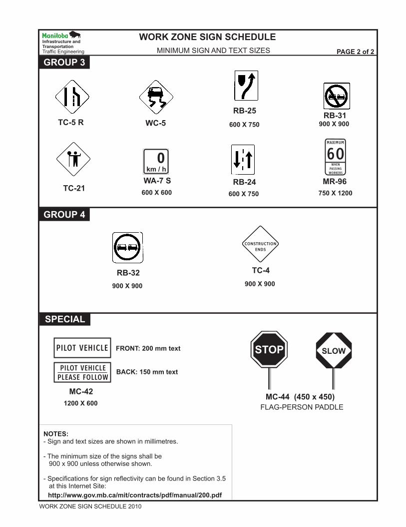
0km / h
STOP
GROUP 3
GROUP 4
SPECIAL
SLOW
NOTES:- Sign and text sizes are shown in millimetres.
- The minimum size of the signs shall be 900 x 900 unless otherwise shown.
- Specifications for sign reflectivity can be found in Section 3.5 at this Internet Site:
Infrastructure andTransportationTraffic Engineering MINIMUM SIGN AND TEXT SIZES
WORK ZONE SIGN SCHEDULE
PAGE 2 of 2
TC-5 R
TC-21WA-7 S
RB-32
MC-42MC-44 (450 x 450)
FLAG-PERSON PADDLE
TC-4
RB-24 MR-96
WC-5
RB-25RB-31
600 X 750
600 X 600
900 X 900
1200 X 600
FRONT: 200 mm text
BACK: 150 mm text
900 X 900
600 X 750 750 X 1200
900 X 900
60MAXIMUM
WHENPASSINGWORKERS
PILOT VEHICLE
PILOT VEHICLEPLEASE FOLLOW
CONSTRUCTION
ENDS
http://www.gov.mb.ca/mit/contracts/pdf/manual/200.pdf
WORK ZONE SIGN SCHEDULE 2010
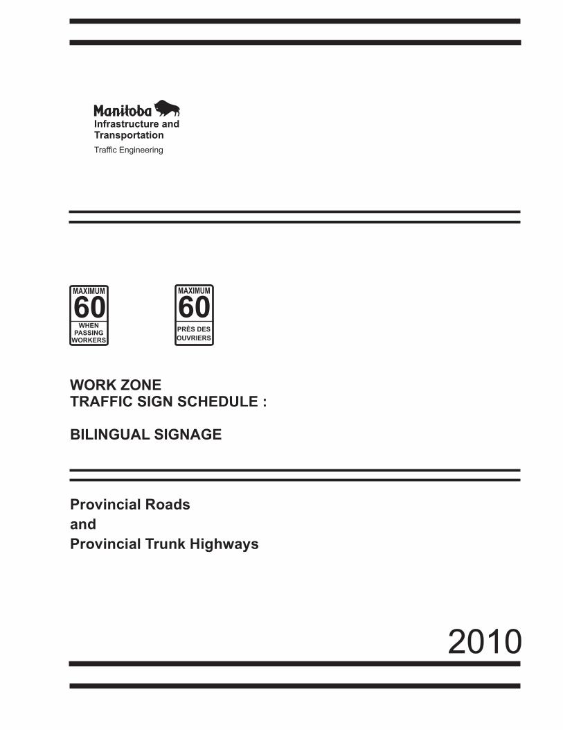
and
Provincial Trunk Highways
Provincial Roads
WORK ZONETRAFFIC SIGN SCHEDULE :
BILINGUAL SIGNAGE
2010
MAXIMUMMAXIMUM
6060PRÈS DES
OUVRIERS
WHENPASSING
WORKERS
Infrastructure andTransportation
Traffic Engineering
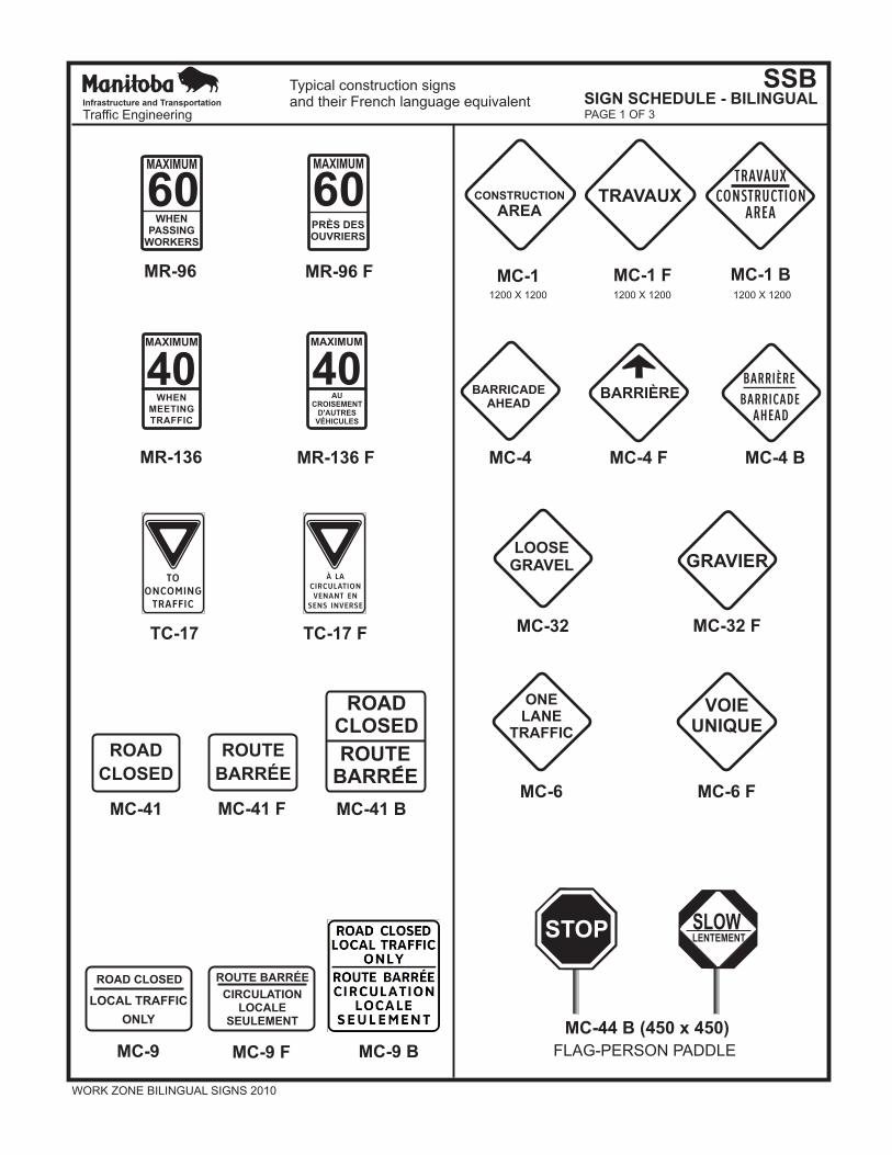
MAXIMUMMAXIMUM
6060PRÈS DESOUVRIERS
WHENPASSING
WORKERS
MR-96 F
MR-136 F
MR-96
MR-136
TC-17 TC-17 F
Typical construction signsand their French language equivalent
MC-41 F MC-41 BMC-41
MC-9 F MC-9 BMC-9
ROUTE
BARRÉE
ROAD
CLOSED
ROUTE BARRÉEROAD CLOSED
CIRCULATIONLOCALE
SEULEMENT
LOCAL TRAFFIC
ONLY
MC-4 MC-4 F MC-4 B
BARRICADEAHEAD
BARRIÈRE
MC-32 MC-32 F
LOOSEGRAVEL GRAVIER
MC-6 FMC-6
VOIEUNIQUE
ONELANE
TRAFFIC
MC-1 F MC-1 BMC-1
TRAVAUXCONSTRUCTION
AREA
WORK ZONE BILINGUAL SIGNS 2010
ROADCLOSED
ROUTEBARREE
SSBSIGN SCHEDULE - BILINGUAL
40WHEN
MEETINGTRAFFIC
MAXIMUM
40AU
CROISEMENTD'AUTRES
VÉHICULES
MAXIMUM
Infrastructure and Transportation
Traffic Engineering
CONSTRUCTIONTRAVAUX
AREA
PAGE 1 OF 3
1200 X 1200 1200 X 1200 1200 X 1200
BARRICADE
BARRIÈRE
AHEAD
TOONCOMINGTRAFFIC
À LACIRCULATIONVENANT EN
SENS INVERSE
STOP SLOWLENTEMENT
MC-44 B (450 x 450)
FLAG-PERSON PADDLE
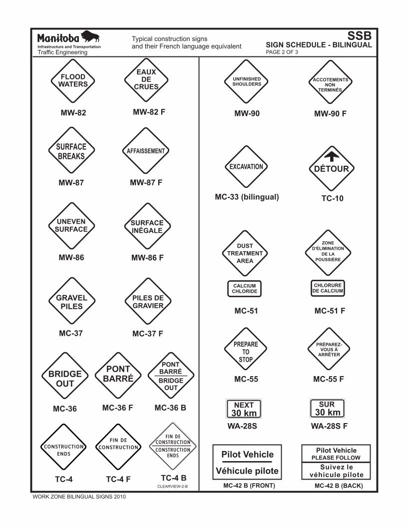
MW-87 MW-87 F
SURFACEBREAKS
AFFAISSEMENT
MW-86 FMW-86
SURFACEINÉGALE
UNEVEN SURFACE
MC-37 FMC-37
GRAVELPILES
PILES DEGRAVIER
MC-36
TC-4 TC-4 F
MC-36 F MC-36 B
BRIDGEOUT BRIDGE
OUT
PONTBARRÉ
PONTBARRÉ
MW-90 MW-90 F
UNFINISHEDSHOULDERS
ACCOTEMENTSNON
TERMINÉS
MC-33 (bilingual)
MC-55 MC-55 F
EXCAVATION
PREPARETO
STOP
ZONE
D'ÉLIMINATION
DE LA
POUSSIÈRE
DUST
TREATMENT
AREA
CHLORUREDE CALCIUM
CALCIUMCHLORIDE
MC-51 MC-51 F
EAUXDE
CRUES
FLOODWATERS
MW-82 MW-82 F
PRÉPAREZ-VOUS À
ARRÊTER
SSBSIGN SCHEDULE - BILINGUAL
Typical construction signsand their French language equivalent
NEXT SUR
30 km 30 km
WA-28S WA-28S F
MC-42 B (FRONT) MC-42 B (BACK)
Pilot VehiclePilot Vehicle
Véhicule piloteSuivez le
véhicule pilote
PLEASE FOLLOW
Infrastructure and Transportation
Traffic Engineering PAGE 2 OF 3
CONSTRUCTION
ENDS
FIN DE
CONSTRUCTION
TC-4 B
CONSTRUCTIONENDS
FIN DECONSTRUCTION
CLEARVIEW-2-B
WORK ZONE BILINGUAL SIGNS 2010
TC-10
DÉTOUR
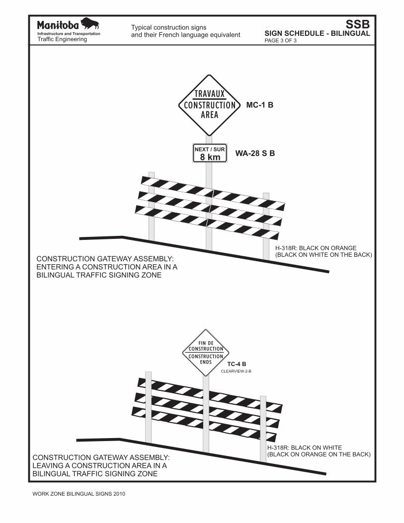
NEXT / SUR
8 km
CONSTRUCTION GATEWAY ASSEMBLY:ENTERING A CONSTRUCTION AREA IN ABILINGUAL TRAFFIC SIGNING ZONE
CONSTRUCTION GATEWAY ASSEMBLY:LEAVING A CONSTRUCTION AREA IN ABILINGUAL TRAFFIC SIGNING ZONE
H-318R: BLACK ON ORANGE(BLACK ON WHITE ON THE BACK)
H-318R: BLACK ON WHITE(BLACK ON ORANGE ON THE BACK)
MC-1 B
WA-28 S B
SSBSIGN SCHEDULE - BILINGUAL
Typical construction signsand their French language equivalentInfrastructure and Transportation
Traffic Engineering PAGE 3 OF 3
CONSTRUCTIONTRAVAUX
AREA
TC-4 B
CONSTRUCTIONENDS
FIN DECONSTRUCTION
CLEARVIEW-2-B
WORK ZONE BILINGUAL SIGNS 2010