Embed Size (px)
Citation preview

WORKBENCHENASSEMBLY INSTRUCTIONS

WEBSITE: www.red-toolbox.com E-MAIL: [email protected] 3WEBSITE: www.red-toolbox.com E-MAIL: [email protected]
RED TOOLBOX WORKBENCH INSTRUCTIONS:
1. Safety Instructions..........................................................Page 4-52. Important Note....................................................................Page 63. General Workbench Dimensions.........................................Page 74. Parts List..............................................................................Page 85. Workbench Parts................................................................Page 96. Hardware Bag A - Parts.....................................................Page 107. Hardware Bag B - Parts.....................................................Page 118. Hardware Bag C - Parts.....................................................Page 129. Instructions - Step by Step...........................................Page 14-47

WEBSITE: www.red-toolbox.com E-MAIL: [email protected] 5WEBSITE: www.red-toolbox.com E-MAIL: [email protected]
EN
DO NOT ATTEMPT TO ASSEMBLE OR OPERATE YOUR RED TOOLBOX WORKBENCH UNTIL YOU HAVE READ THE SAFETY INSTRUCTIONS IN THIS SECTION. THE WORKBENCH SHOULD BE USED BY CHILDREN ABOVE 8 YEARS OLD, AND SHOULD BE ASSEMBLED BY ADULTS ONLY.
WARNING: • DO NOT use this product for scaffolding or as a ladder. • Make sure to insert all pins and fully tighten screws and handles when in use. • Maximum weight capacity 132 lbs / 60kg.
• DO NOT attempt to use your portable workbench unless the safety pins are securely in the locked position and the working plate is free and clean.
• DO NOT load tools weighing more than 65lbs / 30kg.
• DO NOT apply an unbalanced load, this could result in the workbench tipping over.
• DO NOT sit, stand, or climb on the workbench. This could result in falling or tipping over causing serious damage and injury.
• Be sure the workbench’s legs are in the fully opened position and tighten securely before use.
• Before using the workbench, an adult must check that the safety pins on both sides of the plate are fully assembled and in a secure position.
• Folding and reassembly of the working plate and use of the safety pins should only be done by an adult.
• Children under the age of 3 should not touch or use the workbench.
• When using power tools on the workbench, always follow the safety instructions of the power tools’ owner’s manual. Always wear safety glasses or eye shields when operating power tools.
• To prevent injury when opening or closing your workbench, always avoid placing hands or fingers where they could get caught.
• Always keep your work area clean, uncluttered and well lit.
• DO NOT work on floor surfaces that are slippery.
• CAUTION: WORKBENCH SHOULD NOT BE STORED OUTDOORS OR IN A DAMP LOCATION.
• CAUTION: PARENTAL GUIDANCE AND SUPERVISION REQUIRED AT ALL TIMES.
SAFETY INSTRUCTIONS

WEBSITE: www.red-toolbox.com E-MAIL: [email protected] 7WEBSITE: www.red-toolbox.com E-MAIL: [email protected]
EN
FOLLOW THE INSTRUCTIONS DESCRIBED IN THE NEXT SET OF DRAWINGS AND IMAGES TO ASSEMBLE THIS RED TOOLBOX WORKBENCH. The Red Toolbox Workbench is suitable for an entire range of DIY projects. Follow the instructions as described, step by step.To ease the assembly process, each part is marked with a part number. The part number is the same as in the parts list.
PARTS LISTA complete list of parts, their quantities, relevant numbers and descriptions.
• Pay careful attention to the order in which assemblies and sub-assemblies are arranged.
• Use proper tools in good condition and use protective gear to prevent injury.
ENJOY!
IMPORTANT NOTE: GENERAL WORKBENCH DIMENSIONS:SIZE: 790X552.5X879.5 MM / 31.1X21.7X34.7 INCH
Front View
Top View
Side View
General View of Assembled Workbench

WEBSITE: www.red-toolbox.com E-MAIL: [email protected] 9WEBSITE: www.red-toolbox.com E-MAIL: [email protected]
EN PARTS LIST EN WORKBENCH PARTS
PARTS OF THE WORKBENCH: A1 / A2 main leg support, B1 / B2 leg stabilizer, C securing knob, D adjustable pad, E lower cross bar, F1 left leg pillar, F2 right leg pillar, G back panel cross beam, H locking handle, I upper shelf frame, J1 pliers box, J2 files box, J3 screwdrivers sockets box, K drill holder, L tools holder, M back panel, O lower back panel, P1(L) / P2(R) table folding mechanism, Q1 inner table plate, Q2 middle table plate, Q3 front table plate, R table top holder, T table spacer, U double table spacer, V working surface caps.
PARTS OF THE HARDWARE BAG A: A-A1 okolon bushing, A-S1 phillips screw M8 L55, A-N1 self locking torque nut M8, A-W1 washer M8, A-S2 phillips screw M6 L35, A-N2 nut M6, A-W2 washer M6, A-S3 phillips screw M5 L10, A-N3 nut M5, A-W3 washer M5. PARTS OF THE HARDWARE BAG B: B-S1 phillips screw M8 L50, B-N1 table holder nut M8, B-W1 washer M8, B-S2 phillips screw M6 L40, B-N2 nut M6, B-W2 washer M6, B-S3 phillips screw M6 L15, B-N3 nut M6, B-W3 washer M6.
PARTS OF THE HARDWARE BAG C: C-S1 phillips screw M8 L55, C-N1 clip nut M8, C-W1 washer M8, C-S2 phillips screw M6 L38, C-N2 nut M6, C-W2 washer M6.
A1/A21+1
P1(L)/P2(R)1+1
B1/B21+1
CX2
F1X1
F2X1
GX1
DX6
EX1
HX2
J3X1
IX1
J1X1
J2X1
KX1
LX1
MX1
Q1X1
RX4
TX6
UX2
VX8
Q2X1
Q3X1
OX1

WEBSITE: www.red-toolbox.com E-MAIL: [email protected] 11WEBSITE: www.red-toolbox.com E-MAIL: [email protected]
ENEN HARDWARE BAG B - PARTSHARDWARE BAG A - PARTS
A-A1X2
A-S1M8 L55 X 2
A-S2M6 L35 X 6
A-S3M5 L10 X 8
A-N2M6 X 6
A-N3M5 X 8
A-N1M8 X 2
A-W1M8 X 2
A-W2M6 X 6
A-W3M5 X 8
B-S1M8 L50 X 4
B-S2M6 L40 X 4
B-S3M6 L15 X 3
B-N2M6 X 4
B-N3M6 X 3
B-N1M8 X 2
B-W1M8 X 4
B-W2M6 X 4
B-W3M6 X 3
WEBSITE: www.red-toolbox.com E-MAIL: [email protected] 13WEBSITE: www.red-toolbox.com E-MAIL: [email protected]
EN HARDWARE BAG C - PARTS
INSTRUCTIONSSTEP BY STEP
C-S1M8 L55 X 4
C-S2M6 L38 X 4
C-N1M8 X 4
C-N2M6 X 4
C-W1M8 X 4
C-W2M6 X 4
WEBSITE: www.red-toolbox.com E-MAIL: [email protected] 15WEBSITE: www.red-toolbox.com E-MAIL: [email protected]
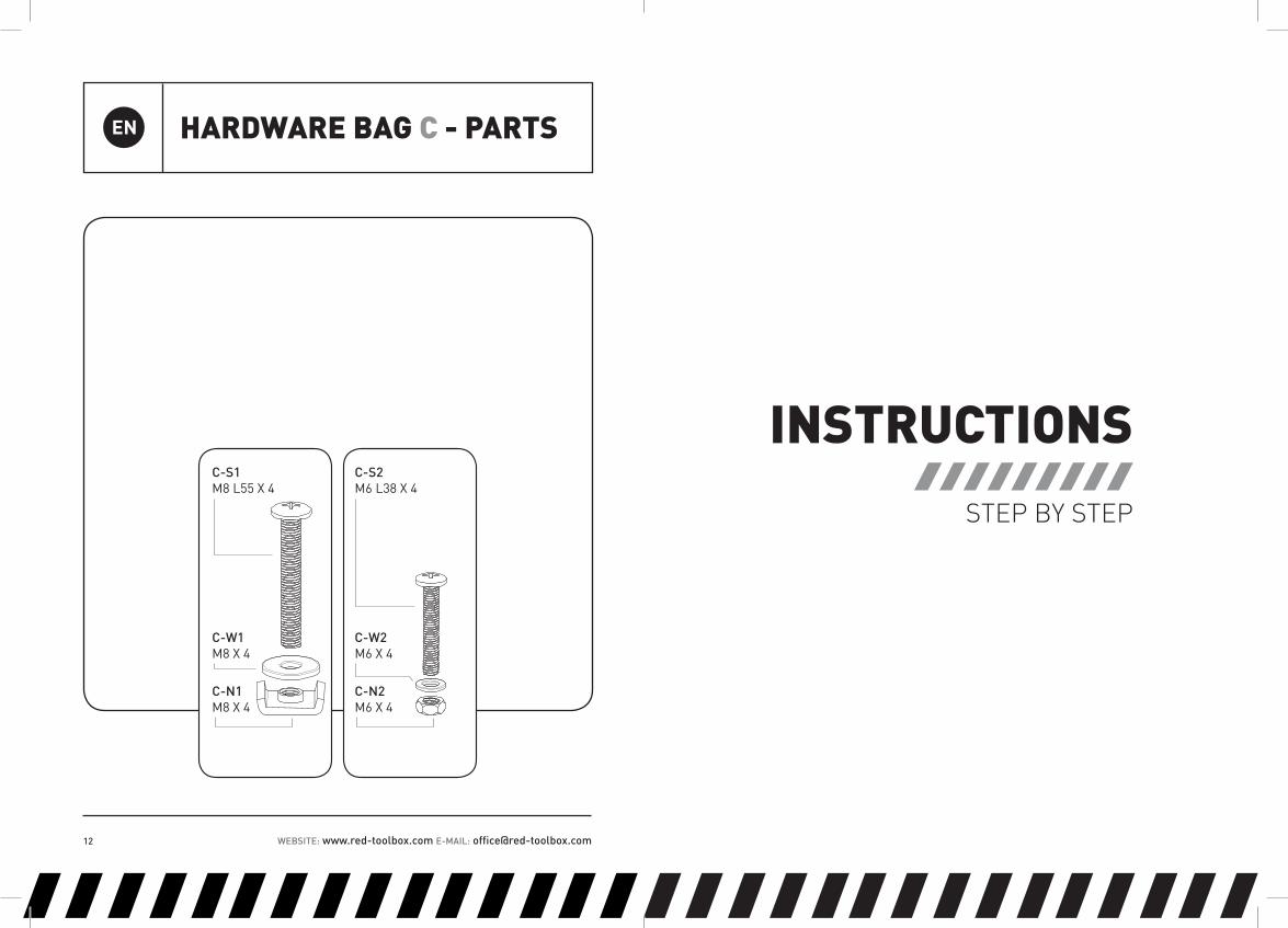
ASSEMBLING THE WORKBENCH LEGS:• Join the main leg support (A1) and the leg stabilizer (B1) to assemble the left leg.• Assemble the right leg the same way, using parts (A2) and (B2).
ASSEMBLING THE LEVELING PADS TO THE LEG STABILIZERS:• Insert the plastic leveling pads (D) from the bottom of the right and the left leg stabilizers (B1, B2).
NOTE: • Each main leg support + leg stabilizer have 3 leveling pads (D), the pads must be adjusted in order to obtain stability and a leveled workbench.• Adjustment of the pads (D) should be done once the workbench is assembled and before using the workbench.• To level the workbench, screw the pads (D) in clockwise or out counter clockwise.
1 2
1,2
3,4
3
10
A1, A2
B1, B2
B1
D

WEBSITE: www.red-toolbox.com E-MAIL: [email protected] 17WEBSITE: www.red-toolbox.com E-MAIL: [email protected]
ASSEMBLING THE LEVELING PADS TO THE MAIN LEG SUPPORTS:• Insert the plastic leveling pads (D) from the bottom of the right and the left main leg supports (A1).• The pads must be adjusted in order to obtain stability and a leveled workbench.
3
ASSEMBLING THE SECURING KNOB:• Install the securing knob (C) to secure the main leg support (A1) to leg stabilizer (B1) of the left leg.• Tighten the securing knob (C) to prevent undesirable moves.• Repeat the same procedure with the right leg.
4
1
3
10
1
9
3
A1
A1
B1
B1
C
D

WEBSITE: www.red-toolbox.com E-MAIL: [email protected] 19WEBSITE: www.red-toolbox.com E-MAIL: [email protected]
• If you correctly followed the instructions above, both legs of the workbench should be assembled.
5
ASSEMBLING THE LOWER CROSS BAR:At each end of the lower cross bar there are 2 holes.
• Insert the screws (A-S2) through these holes and align with both the legs. • Using the screw (A-S2), washer (A-W2) and nut (A-N2), tighten the lower cross bar (E) to both the left and right leg.
612
13
14
11
A-S2
A-W2
A-N2
E
A-S2

WEBSITE: www.red-toolbox.com E-MAIL: [email protected] 21WEBSITE: www.red-toolbox.com E-MAIL: [email protected]
• If you correctly followed the instructions above, both legs of the workbench should be assembled.
7
08. ASSEMBLING THE LEG PILLARS:• Insert the left leg pillar (F1) in the left main leg support (A1).• Pay attention to the position of the leaf (F1a) protrusion sticking out from the leg pillar. • The leaf must face the internal side with the inclined edge facing upwards.
PAY ATTENTION TO THE EXISTING HOLES.*• These holes determine the desired height of the workbench.• Choose your desired height and adjust accordingly.
09. • Repeat the same procedure with the right leg pillar (F2).
8
9
F1
F1a
A1
F2

WEBSITE: www.red-toolbox.com E-MAIL: [email protected] 23WEBSITE: www.red-toolbox.com E-MAIL: [email protected]
ASSEMBLING THE UPPER CROSS BEAM:• Place the upper cross beam (G) behind the leg pillar (F1). • Using the two screws (A-S2), washers (A-W2) and nuts (A-N2), install the upper cross beam (G) to the left leg pillar (F1). • Insert the screws (A-S2) to the two lower holes out of three.• Repeat the same procedure with the right leg pillar (F2).
NOTE:• Insert the screws (A-S2) into the 2 lower holes of the leg pillars.
10
HEIGHT ADJUSTMENT:• Select the desired height and fasten the locking handles (H) inside the appropriate holes, tighten the locking handles.
NOTE: • Align the leg pillars (F1 and F2) at the same height prior to inserting the locking handles (H).
20 2015 15
11F1 F2G A-N2 A-W2
A-S2G
A-N2
A-W2
A-S2
H HF1 F2
A-S2

WEBSITE: www.red-toolbox.com E-MAIL: [email protected] 25WEBSITE: www.red-toolbox.com E-MAIL: [email protected]
• If you correctly followed the instructions above, the frame of the workbench should be assembled.
12
ASSEMBLING THE DRILL HOLDER TO THE UPPER SHELF:• Install the drill holder (K) to the right side of the upper shelf (I), using 4 screws (A-S3), washers (A-W3) and nuts (A-N3).• Pay attention to insert the screws from the inside of the shelf outwards.• Use a proper spanner and screwdriver.
2421 29 28 27
13
I KA-S3 A-W3 A-N3
A-S3

WEBSITE: www.red-toolbox.com E-MAIL: [email protected] 27WEBSITE: www.red-toolbox.com E-MAIL: [email protected]
• If you correctly followed the instructions above, the drill holder of the upper shelf should be assembled.
14
ASSEMBLING THE TOOLS HOLDER TO THE UPPER SHELF:• Install the tools holder (L) to the left side of the upper shelf (I), using 4 screws (A-S3), washers (A-W3) and nuts (A-N3). • Pay attention to insert the screws from the inside of the shelf outwards.• Use a proper spanner and screwdriver.
2627 28 29 21
15
A-N3 A-W3 A-S3L I
A-S3
WEBSITE: www.red-toolbox.com E-MAIL: [email protected] 29WEBSITE: www.red-toolbox.com E-MAIL: [email protected]
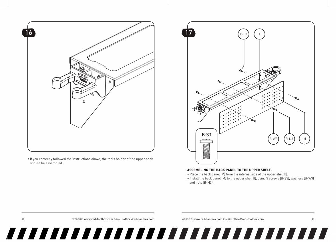
• If you correctly followed the instructions above, the tools holder of the upper shelf should be assembled.
16
ASSEMBLING THE BACK PANEL TO THE UPPER SHELF:• Place the back panel (M) from the internal side of the upper shelf (I).• Install the back panel (M) to the upper shelf (I), using 3 screws (B-S3), washers (B-W3) and nuts (B-N3).
17
30
32 21
13 14
B-S3
B-W3 B-N3 M
I
B-S3

WEBSITE: www.red-toolbox.com E-MAIL: [email protected] 31WEBSITE: www.red-toolbox.com E-MAIL: [email protected]
• If you correctly followed the instructions above, the back panel of the upper shelf should be assembled.
18
• It is highly recommended to assemble the tool trays (J1, J2, J3) at the end to ease further assembly steps.
MOUNTING THE TOOL TRAYS ON THE UPPER SHELF:• Add the three tool trays (J1, J2, J3). their size is the same. • Feel free to customize your upper shelf.
1925
21
22 23J3 J1
I
J2
WEBSITE: www.red-toolbox.com E-MAIL: [email protected] 33WEBSITE: www.red-toolbox.com E-MAIL: [email protected]
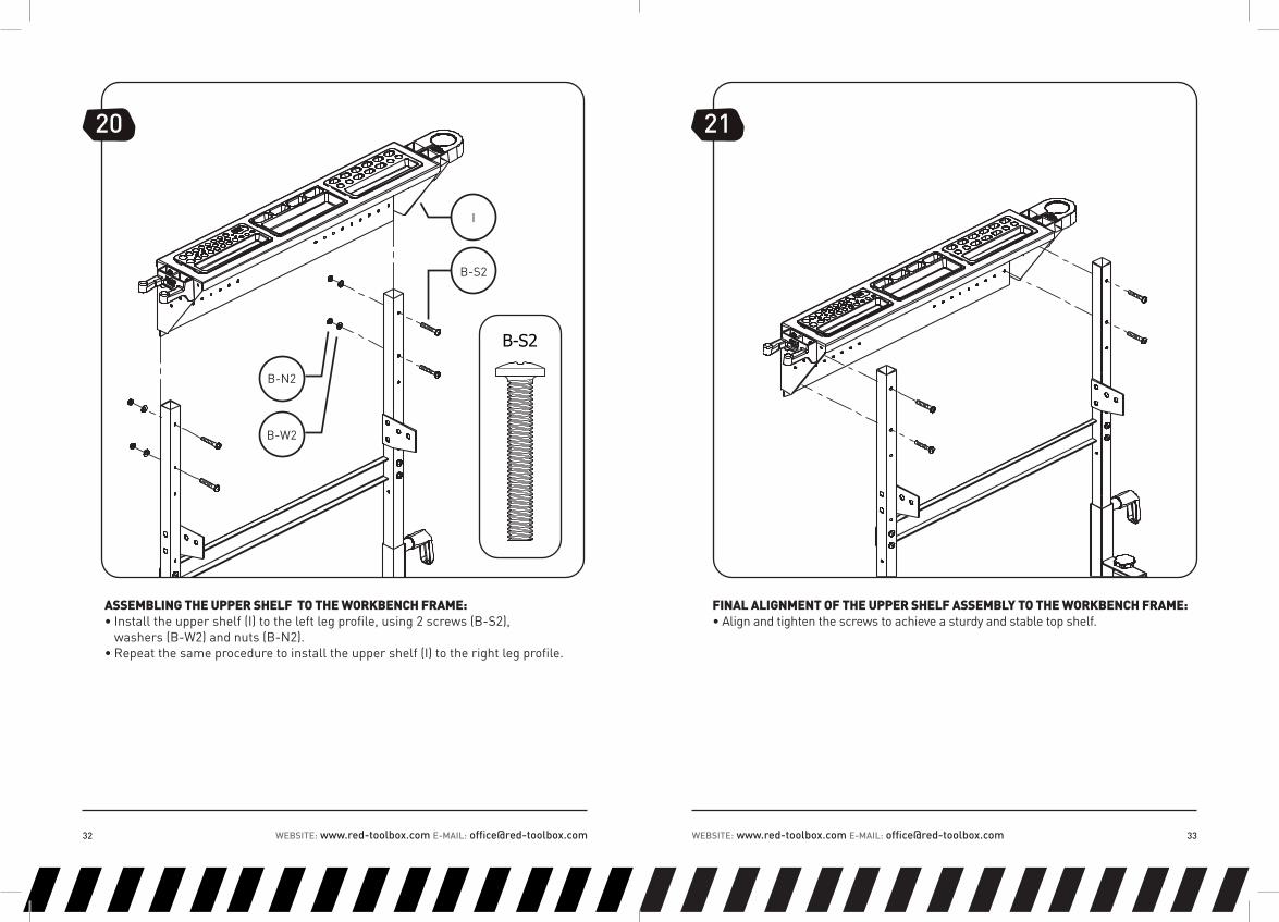
ASSEMBLING THE UPPER SHELF TO THE WORKBENCH FRAME:• Install the upper shelf (I) to the left leg profile, using 2 screws (B-S2), washers (B-W2) and nuts (B-N2).• Repeat the same procedure to install the upper shelf (I) to the right leg profile.
FINAL ALIGNMENT OF THE UPPER SHELF ASSEMBLY TO THE WORKBENCH FRAME:• Align and tighten the screws to achieve a sturdy and stable top shelf.
21
21
19
13
14
20
I
B-S2
B-N2
B-W2
B-S2

WEBSITE: www.red-toolbox.com E-MAIL: [email protected] 35WEBSITE: www.red-toolbox.com E-MAIL: [email protected]
• If you correctly followed the instructions above, the upper shelf should be assembled.
22
ASSEMBLING THE LOWER BACK PANEL:• Install the lower back panel (O) to the left leg profile, using 2 screws (C-S2), washers (C-W2) and nuts (C-N2).• Repeat the same procedure to install the lower back panel (O) to the right leg profile.
23
C-S2 C-W2 C-N2 O
C-S2

WEBSITE: www.red-toolbox.com E-MAIL: [email protected] 37WEBSITE: www.red-toolbox.com E-MAIL: [email protected]
NOTE: • Pay attention to the force implied when tightening the nuts to prevent damage to the lower back panel.
• If you correctly followed the instructions above, the lower back panel should be assembled.
2524

WEBSITE: www.red-toolbox.com E-MAIL: [email protected] 39WEBSITE: www.red-toolbox.com E-MAIL: [email protected]
ASSEMBLING THE TABLE FOLDING MECHANISM:In the next step install the table folding mechanism (P2) and safety pin.
• Partially fasten the table folding mechanism (P2) to the left leg profile, using screw (A-S1), okolon sleeve (A-A1), washer (A-W1) and torque nut (A-N1).• Repeat the same assembly procedure with the right Leg Profile.• Tighten screws (A-S1)• Check proper function.
• If you correctly followed the instructions above, the table folding mechanism should be assembled.
• Now check the table folding mechanism hinges operation: open and fold a few times to assure proper function.• In order to secure the table to its right working position, make sure the workbench arms are open and fastened to the support rods by tightening the locking knobs. • Make sure safety pins are securely inserted in the right position.
2726
A-S1
A-A1
P2
A-W1
A-N1
A-S1
WEBSITE: www.red-toolbox.com E-MAIL: [email protected] 41WEBSITE: www.red-toolbox.com E-MAIL: [email protected]
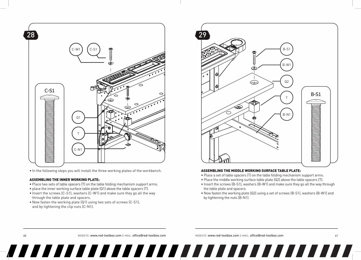
• In the following steps you will install the three working plates of the workbench.
ASSEMBLING THE INNER WORKING PLATE:• Place two sets of table spacers (T) on the table folding mechanism support arms. • place the inner working surface table plate (Q1) above the table spacers (T).• Insert the screws (C-S1), washers (C-W1) and make sure they go all the way through the table plate and spacers.• Now fasten the working plate (Q1) using two sets of screws (C-S1), and by tightening the clip nuts (C-N1).
ASSEMBLING THE MIDDLE WORKING SURFACE TABLE PLATE:• Place a set of table spacers (T) on the table folding mechanism support arms. • Place the middle working surface table plate (Q2) above the table spacers (T).• Insert the screws (B-S1), washers (B-W1) and make sure they go all the way through the table plate and spacers.• Now fasten the working plate (Q2) using a set of screws (B-S1), washers (B-W1) and by tightening the nuts (B-N1).
C-W1
Q1
T
C-N1
C-S1
28
C-S1
51
49
43
46
50
T
B-S1
B-W1
B-N1
Q2
29
B-S1

WEBSITE: www.red-toolbox.com E-MAIL: [email protected] 43WEBSITE: www.red-toolbox.com E-MAIL: [email protected]
• If you correctly followed the instructions above, the inner and middle working surface table plates should be assembled.
30
ASSEMBLING THE FRONT WORKING PLATE:• Place a set of double table spacers (U) on the table folding mechanism support arms. locate the front working plate (Q3) above the double table spacers (U).• Insert the screws (B-S1) and washer (B-W1) through out the plate and spacer (U).• Install the working plate (Q3) using the set of screws (B-S1).• Tighten to the back inner moving part of the table folding mechanism (P2).
37
49
44
47
34
31B-S1
B-W1
U
P2
Q3
B-S1

WEBSITE: www.red-toolbox.com E-MAIL: [email protected] 45WEBSITE: www.red-toolbox.com E-MAIL: [email protected]
• If you correctly followed the instructions above, the inner, middle and the front working plates should be assembled.
32
ASSEMBLING THE WORKING SURFACE CAPS:• Place and manually install the 8 plastic working surface caps (V) on the working surface table plates.
33
V
WEBSITE: www.red-toolbox.com E-MAIL: [email protected] 47WEBSITE: www.red-toolbox.com E-MAIL: [email protected]
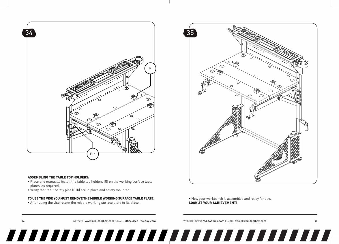
ASSEMBLING THE TABLE TOP HOLDERS:• Place and manually install the table top holders (R) on the working surface table plates, as required.• Verify that the 2 safety pins (F1b) are in place and safety mounted.
TO USE THE VISE YOU MUST REMOVE THE MIDDLE WORKING SURFACE TABLE PLATE.• After using the vise return the middle working surface plate to its place.
34
• Now your workbench is assembled and ready for use.LOOK AT YOUR ACHIEVEMENT!
35
R
F1b

ENMANUFACTURER: RED TOOL BOX LTD. ADDRESS: ROOM 1109, BUILDING #1, HIGH-TECH DEVELOPMENT PLAZA, NINGBO NATIONAL HI-TECH ZONE, NINGBO, CHINA
WWW.RED-TOOLBOX.COM
IWB001EN070313


![Robotics T OOLBO X - phoenix.goucher.edujillz/cs325_robotics/robot.pdf · well as analyzing results from experiments with real robots. ... the book of P aul[1 ], ... Classical as](https://img.pdfslide.net/doc/110x75/5b8130587f8b9a2b678bd919/robotics-t-oolbo-x-jillzcs325roboticsrobotpdf-well-as-analyzing-results.jpg)


![shodhganga.inflibnet.ac.inshodhganga.inflibnet.ac.in/bitstream/10603/38858/6/06_abstract.pdf · Website G localization [Website Globalization Website localization], Website Translation,](https://img.pdfslide.net/doc/110x75/5ec9bd2c60e8c147cb59663b/website-g-localization-website-globalization-website-localization-website-translation.jpg)