Embed Size (px)
Citation preview

Author’s Name Name of the Paper Session
DYNAMIC POSITIONING CONFERENCE September 28-30, 2004
Workboats / OSVs
Crew boat Station Keeping
Challenges and Solutions
Lars Kristian Moen
Kongsberg Maritime, Kongsberg Norway

Lars Kristian Moen Workboats / OSV’s Crew boat Station Keeping, ..
DP Conference Houston
September 28-30, 2004
Page 2 of 17
Introduction In the beginning of the offshore GOM activity, crew boats were built and used for transportation of personnel and cargo to and from the offshore installations not far away from the coast. Unlike Offshore Supply Vessels, crew boats have usually been optimized for speed more than maneuverability, cargo capacity and station keeping capability. Crew boats traditionally operate like a fast ferry between shore terminals and offshore installations. Gradually the size of crew boats built in the GOM has increased and the difference between a traditional crew boat and an OSV has been reduced. With increased capacity for deck load, fuel, drilling mud, drinking water, dry cargo in addition to added crew capacity and transit speed above 30 knots this type of vessel now challenge the OSV’s especially for the remote deepwater support. The crew boat migration into the OSV type of vessel has lead to the introduction of the term Fast Support Intervention Vessel (FSIV). The FSIV is optimized for time-sensitive transport of both cargo and offshore workers to the remote deepwater fields. Originally the "Intervention" term was used to indicate that the vessel could intervene quickly with urgent cargoes. Today the term Fast Supply Vessel (FSV) probably supercedes the original FSIV. In 2000 the first GOM crew boat installed Dynamic Position control system and was later upgraded to become ABS DPS-1 compliant (from a DP control system perspective). The motivation for the vessel owner was to optimize the operation alongside the offshore installation with respect to time, regularity and safety. This paper will focus on the largest crew boats with length above 150 ft and deadweight above 300 metric ton (MT). Approximately 16 of these vessels in operation in the GOM have DP systems. Typical figures for “DP size” crew boats: Fuel Drill
Mud/Water Lightship / Deadweight
Max Speed Passengers
~50,000 USG ~80,000 USG 200-300 MT 200-500 MT
20-35 kts 70-100
Engineering, commissioning and operation of a DP system for an offshore crew boat meant some new challenges for both the DP manufacturer and the crew boat operator. This paper will discuss some of the challenges and some of the solutions. Offshore crew boats can be found in Far East, Middle East, West Africa, Brazil, Mexico and Gulf Of Mexico. According to Marcon International Inc. above 50% of the crew boats operate in the United States. A typical offshore crew boat in the GOM will be in shuttle operation from GOM terminals like Port Fourchon, Leeville, Morgan City and the manned offshore installations. According to USCG there is approximately 900 manned fixed production units on the shelf and 20 in the deepwater (water depth above 100 ft). In addition there is a number of deepwater offshore drilling units with requirement for fuel, drilling mud and other necessities for their uninterrupted operation. Today approximately 200 crew boats operate in the offshore US GOM.
Seabulk
22
Tidewater 26 Seacor 50 Trico 17

Lars Kristian Moen Workboats / OSV’s Crew boat Station Keeping, ..
DP Conference Houston
September 28-30, 2004
Page 3 of 17
Figure 1, Remote Offshore Installation in GOM
DP Crew boats One of the major offshore crew boat operators in the GOM expresses: “Our initial motivation and the motivation that still drives us to DP a crew boat is to have safer and more efficient vessels for our clients. With multi engine vessels and the need to stay on location longer, DP proves a very efficient tool to hold the vessel in position.” As crew boats become bigger and carry more personnel and cargo the on and offloading part next to the offshore installation will have more focus. In the OSV industry, DP and joystick systems have been used for this kind of operation for more than 20 years. OSV’s normally have plenty of bow thrust and stern thrust capacity to obtain thrust forces and rotational moment in all 3 (surge, sway and yaw) degrees of freedom. Crew boats however are still built for transit speed more than excellent maneuverability in all degrees of freedom. With 4-6 main propellers each 1200-2000 BHP and one 100-300 BHP thruster in the bow, station keeping strategy needed to be adjusted. All DP control systems need position measurements. Like for OSV’s working close to offshore installations availability of accurate absolute measurement and relative measurements needs attention. The dynamic nature of crew boats compared to vessels with much more displacement and the response time (time for propulsion actuators to react to the command signal from the DP control system) for propulsion equipment is focus area. As for all critical DP operations the DP Capability of the vessel and Failure Mode Effect Analysis should have focus. The US CG DP memorandum from January 2003 defines requirements for support vessels involved with transfer of hazardous material. The crew boat operation alongside offshore installations resembles the OSV operation more and more and the USCG requirement seems relevant also for new crew boats and FSIV’s.

Lars Kristian Moen Workboats / OSV’s Crew boat Station Keeping, ..
DP Conference Houston
September 28-30, 2004
Page 4 of 17
Evolution of Vessel Requirements
Early 70’s 80’s 90’s Now and future
Drilling Dominated by jackups
Semi’s go deeper, get bigger
Drive to deep water
Harsh environment
Water Depth Less than 500 ft Up to 1,000 ft 5,000 ft Above 10,000 ft
Impact on vessel requirements
Drivers Delivery Delivery of
materials in larger quantity
Vessel controllability, station – keeping, size, efficiency
Cargo Needs Limited requirements Bulk on deck Fuel and water under deck No liquid mud
Liquid mud mixed ashore and placed in tanks Bulk systems go under deck, deliver in quantity
Much larger capacities of liquid mud needed. Methanol carriage increases due to deep-water production. Multiple grades of liquid mud
Personnel needs All personnel taken by boat Virtually no cargo on crew boats
Helicopters begin to be used for passengers
Comfort and safety of passengers. High speed. More passengers by helicopter. Fast cargo combines with crew boat.
Travel Distance 50 miles offshore Generally less than 150 miles 150 miles offshore
Lars Kristian Moen Workboats / OSV’s Crew boat Station Keeping, ..
DP Conference Houston
September 28-30, 2004
Page 5 of 17
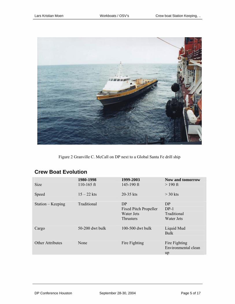
Figure 2 Granville C. McCall on DP next to a Global Santa Fe drill ship
Crew Boat Evolution 1980-1998 1999-2003 Now and tomorrow Size 110-165 ft 145-190 ft > 190 ft
Speed 15 – 22 kts 20-35 kts > 30 kts
Station – Keeping Traditional DP
Fixed Pitch Propeller Water Jets Thrusters
DP DP-1 Traditional Water Jets
Cargo 50-200 dwt bulk 100-500 dwt bulk Liquid Mud Bulk
Other Attributes None Fire Fighting Fire Fighting Environmental clean up

Lars Kristian Moen Workboats / OSV’s Crew boat Station Keeping, ..
DP Conference Houston
September 28-30, 2004
Page 6 of 17
Figure 3 Crew boat Location, ref. [1]
Figure 4 July 2004 Day Rates and Fleet Utilization, ref. [2]
Figure 5, Gulf Of Mexico oil and gas fields, ref [3]
Lars Kristian Moen Workboats / OSV’s Crew boat Station Keeping, ..
DP Conference Houston
September 28-30, 2004
Page 7 of 17
Vessel Lightship/
Deadweight Length Engines Propulsion
P. A. McCall Seacor
219 MT 417 MT
183 ft 6 Cummins KTA-38M 8100 BHP
6 46*42 prop 4 rudders 300 BHP drop down azimuth
Granville C. McCall Seacor
259 MT 433 MT
190 ft 5 V-16 Cummins KTA-50-M2 9000 BHP
5 Four blade Teignbridge 54*54 2 rudders 400 BHP Azimuth
Fast Bandit ECO
165 ft
Fast Bullet ECO
165 ft
Keith McCall Seacor
206 MT 305 MT
177 ft 4 V-16 Cummins KTA-50-M2 7,200 BHP
4 Hamilton Water Jets 200 HP bow tunnel 200 HP bow azimuth
Seth McCall Seacor
206 MT 305 MT
177 ft 4 V-16 Cummins KTA-50-M2 7,200 BHP
4 Hamilton Water Jets 200 HP bow tunnel 200 HP bow azimuth
Empire State Seacor
219 MT 412 MT
170 ft 4 Cummins KTA 50 7,300 BHP
4 Teignbridge Thrustmaster 200 HP bow azimuth
Gloria McCall Seacor
218 MT 402 MT
170 ft 4 Cummins KTA 50 7,300 BHP
4 Teignbridge Thrustmaster 200 HP bow azimuth
HOS Hotshot Hornbeck
? MT 263 MT
160 ft 4 CAT 3512 6,300 BHP
4 VPP, 4-blade 1 Key Power KP-18 bow thruster
Vickie Tide (FSV) Tidewater
175 ft 5 V-16 Cummins KTA-50-M2 9000 BHP
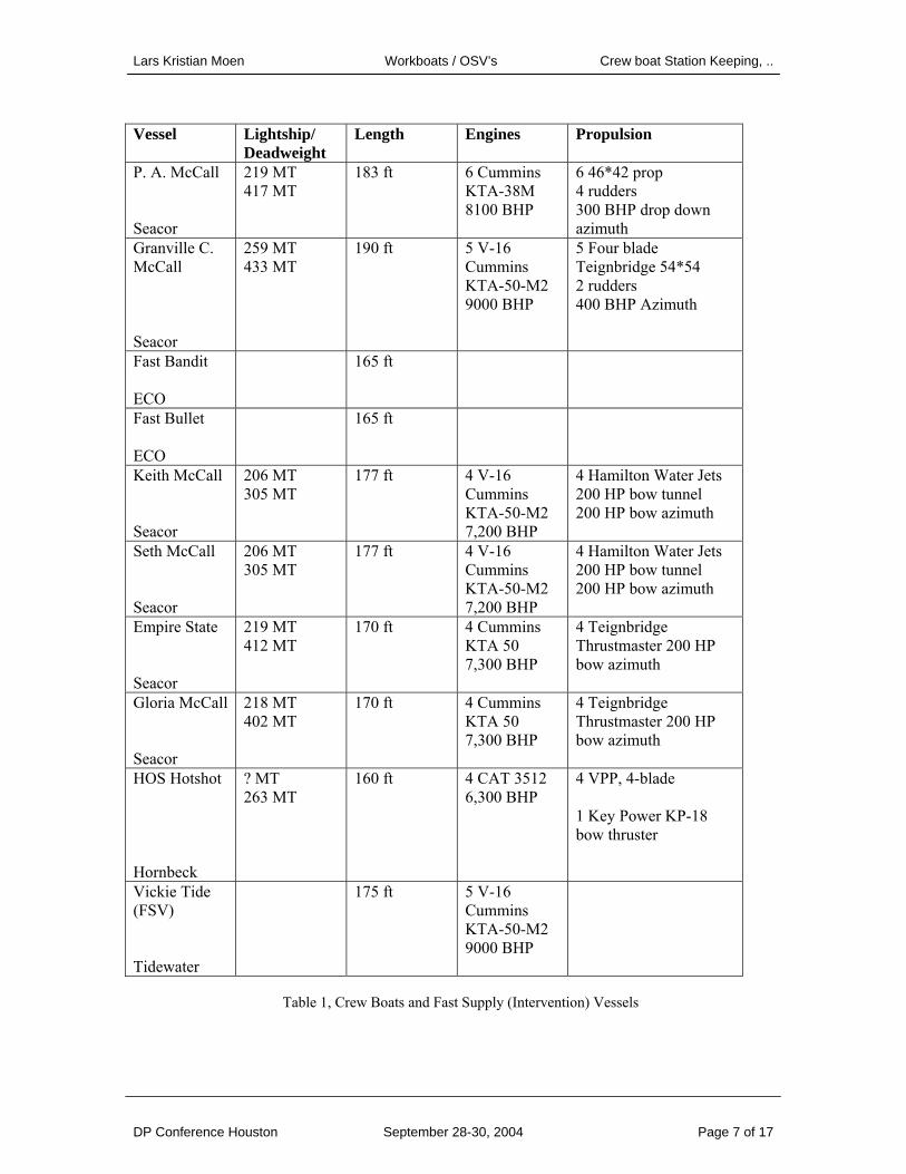
Table 1, Crew Boats and Fast Supply (Intervention) Vessels

Lars Kristian Moen Workboats / OSV’s Crew boat Station Keeping, ..
DP Conference Houston
September 28-30, 2004
Page 8 of 17
DP Operation for Crew Boats The crewboat DP system is used when approaching the offshore installation and for the offloading operation. During offloading the crew boat will be 5-50 meters away from the offshore installation. When approaching the offshore installation the position of cranes and other on- and offloading infrastructure together with the environmental situation will be considered. If possible a location on the lee side of the installation and with environmental forces that will make the DP vessel drift away will normally be used. The selected location will usually be a compromise between optimizing these factors and crane position and cargo location on deck. Requirements related to consequence evaluations The IMO Guidelines [5] for DP operations state that Owner and Operator shall determine which equipment class should be applied for a specific operation by performing a risk analysis to document all aspects of the operation. Risk analysis should take into account: - technical evaluation of vessel and DP system - evaluation of planned operation, highlighting critical phases - emergency procedures - relevant experience of crew The Petroleum Safety Authority of Norway states that in the event of dynamic positioning near other floating facilities or vessels, special consideration should be given to: - mutual movement and different movement patterns - the effect of current and noise from propellers - interference with or joint transponders - varying shadow effects for antennas connected to the dynamic positioning system US CG memorandum from January 2003 (ref. [3]) related to DP of OSVs while transferring hazardous material refer to the above IMO guidelines when it comes to equipment class and consequence analysis. The background for the USCG guideline was the increasing number of OSVs without conventional mooring while transferring, but DP “mooring” and the lack of established procedures and guidelines. The USCG repeats the IMO definition of what a DP vessel is: “Dynamically positioned vessel (DP vessel) means a unit or a vessel which automatically maintains its position (fixed position or predetermined track) exclusively by means of thruster force.”. The definition of DP system is also repeated: “The complete installation necessary for dynamically positioning a vessel comprising the following subsystems: Power system, thruster system and DP control system.” The USCG memorandum states that a DP system with redundancy is required to provide an equivalency to passive mooring systems. Since however a large number of GOM OSV’s have DP systems without redundancy, and proven to be highly reliable DP systems and a typical OSV offloading operation on DP is not a long-term operation alternative degrees of redundancy will be accepted. The DP system needs sufficient redundancy so that if problems occur there will be time to safely terminate the transfer operation before drift off. From reference [3] the following table illustrate guidelines from USCG on what is considered sufficient redundancy in DP system components.

Lars Kristian Moen Workboats / OSV’s Crew boat Station Keeping, ..
DP Conference Houston
September 28-30, 2004
Page 9 of 17
Table 2, USCG guidelines from ref.[4]
Relative Station Keeping Station keeping a DP vessel next to an offshore installation can be station keeping without adaptation to the absolute movement of the offshore installation or according to the Follow Target mode. Most offshore installations are large superstructures and their movements are usually with low amplitude and long oscillating period. Examples are fixed steel platforms, TLP’s, SPAR’s and large drilling semi’s and mono-hull vessels. In the GOM, the offshore installations have been considered fixed for the duration of the DP operation of the OSV or crew boat. Drill ships will sometimes change heading, but when this takes place when a support vessel is on DP next to the drill ship with relative position measurements in use the operation is coordinated manually between the crew of the drill ship and the support vessel. Of the more dynamic offshore installations supported by OSV’s and Crew boats are turret moored FPSO’s without automatic heading stabilization. For offshore loading operations the dynamic nature of FPSO’s and other offloading arrangements it has been required to take the movements of the “target” into consideration in the DP algorithms of the shuttle tanker.

Lars Kristian Moen Workboats / OSV’s Crew boat Station Keeping, ..
DP Conference Houston
September 28-30, 2004
Page 10 of 17
Also for pipe carriers alongside a pipe layer in operation and support vessels next to FPSO’s it has been successful to operate the DP system in a Follow Target mode rather than pure Station Keeping with a combination of relative and absolute measurements. The key in defining the station keeping strategy to be used is to consider the movements of the target and the relative position measurements to be used. Normally the movements (if any) are slow compared to the dynamics of the DP vessel and more or less periodic.
Figure 6 Relative Positioning with different mutual vessel dynamics Position Reference Systems From the first DP crew boat in GOM a combination of relative and absolute position measurements have been used. Absolute Position Reference
A position measurement that gives information about DP vessel movements only. A DGPS measurement will pr. definition be absolute. DGPS will offer position measurements in global earth fixed coordinates while e.g. HiPAP measurements from a seabed transponder will be in a local coordinate system.
Relative Position Reference
A position measurement that gives information about the relative position between the DP vessel and some reflector or transponder mounted somewhere. If mounted on a moving target this measurement can not directly be compared and combined with absolute measurements. If the moving target has limited amplitudes and long oscillating periods the measurement can however be treated as an absolute measurement.
DGPS Differential Global Positioning System
Measuring the absolute position in latitude and longitude for the DP vessel (crew boat) The DGPS unit will use GPS and/or GLONASS satellites to calculate the position. Differential correction can be from satellite systems or radio signals (where available) The DGPS receiver is interfaced to the DP system according to the NMEA 0183 standard
Hydroacoustic With transponder on the seabed the position measurement is relative to the transponder

Lars Kristian Moen Workboats / OSV’s Crew boat Station Keeping, ..
DP Conference Houston
September 28-30, 2004
Page 11 of 17
e.g. HiPAP
location (X, Y, Z)., but according to the definition above be an absolute measurement. Measurements will give information about DP vessel movements since the transponder location is fixed. When the transponder is mounted on e.g. a ROV the transponder is defined as “mobile” and is used to monitor ROV position and to generate new position setpoint for the DP vessel when in Follow Target (Sub) mode. This will then be a relative position measurement.
DARPS Differential Absolute and Relative Positioning System With one DGPS on the DP vessel and one DGPS on the offshore installation each will calculate the absolute position. By radio communication between the two systems the two absolute positions is used to calculate the relative position between the offshore installation and the DP vessel. The DARPS on the DP vessel will offer both absolute and relative position to the DP system. In addition to relative position information the link will normally be used to transfer target vessel heading and other relevant information.
Fanbeam Laser system measuring the relative position as range and bearing between the laser unit on the DP vessel and a reflective target mounted on the target installation. Based on Petrobras requirements for OSV’s operating next to FPSO’s the multi target Fanbeam has been developed and used to track several reflectors on the target and from this the DP system will have several relative position measurements to the target vessel and can now operate in Follow Target mode. With several position measurements the DP can follow not only target position, but also heading if required.
CyScan Relative position measurement system using laser technology
RADius To be launched as DP reference in the GOM during fall 2004. Testing in North Sea environment started winter 2003-2004. Radar based relative system with interrogator on the DP vessel and one or more transponders on the target. No moving parts and individual electronic identification of the target transponders. Target transponder needs power (can be from battery).
Figure 7, Fanbeam laser unit Absolute position measurements will always give information about DP vessel movements. A relative position measurement will give information about movement of the DP vessel or the target where the reflector or DARPS counterpart is mounted. Knowledge of the movements of the target is required when using the relative position measurement together with the absolute measurement for

Lars Kristian Moen Workboats / OSV’s Crew boat Station Keeping, ..
DP Conference Houston
September 28-30, 2004
Page 12 of 17
establishing the DP vessel model. If the relative measurement contains information colored by a moving target the blending of the systems can go wrong and the relative system should instead be used as a setpoint generator in Follow Target mode.
Figure 8, Shuttle Tanker with DARPS and other position measurement systems
Figure 9, RADius Relative Position Reference
Challenge #1: When operating in traditional DP station keeping and the superstructure is considered fixed and the DP system blend absolute and relative measurements to establish the vessel model (low motion amplitude and long oscillation period). For some reason the superstructure moves more than expected. The relative measurements will not only contain information about DP vessel movement. Blending this measurement with DGPS absolute measurement can disturb the vessel model and can result in position oscillations. Challenge #2: When operating in Follow Target mode with absolute measurements (usually DGPS) to establish vessel model and relative measurements (usually Fanbeam) to adjust position setpoint. The absolute position measurement can be disturbed caused by e.g. shadowing. Little redundancy in absolute measurements leaves the DP system with only relative measurements and fall back control strategies should be implemented. Challenge #3: DP crew boat operators report that due to the (small) size of the crew boat compared to the offshore installations they operate next to, availability of good position measurements should be improved. Awareness of GPS satellite constellation and experiments with Fanbeam reflectors has improved the problem, but the problem can not be considered as solved. The new RADius position reference
Lars Kristian Moen Workboats / OSV’s Crew boat Station Keeping, ..
DP Conference Houston
September 28-30, 2004
Page 13 of 17
will be tested in the GOM during fall 2004 and will add redundancy with a totally different measurement principle. DP Class and other requirements Almost all new DP vessels ordered in the GOM after January 2000 have been built with or according to IMO Class 1 or 2. In addition to new build projects a number of retrofit projects have taken place to upgrade existing fleet to be according to IMO Class 1. The basic requirements for Class 1 is more than 1 position reference system and a independent joystick system in addition to the main DP. An increasing percentage of DP vessels built in the GOM are built according to IMO Class 2. For Class 2 the main DP shall be with redundancy and minimum 3 position reference systems are required. Additional investment for redundancy in power plant, power management, propulsion redundancy and FMEA analysis will be required. Normally OSV’s designed for Class 2 are built with propulsion redundancy in the bow and in the stern. Even with optimum utilization of main propulsion after a bow thruster failure the station keeping capability of the crew boat will be very limited. Requirements by class doesn’t state necessary capability requirements however and in principle class 2 classification should be possible also for a crew boat with one bow thruster. Almost all DP vessels built or retrofit in the GOM are with ABS and then according to ABS DPS-1 or DPS-2. The IMO DP requirements and the interpretations by class societies like ABS and DnV doesn’t address the difference between relative and absolute measurements for the DP vessel and how the measurements are used within the DP system. If the offshore installation has significant movements the relative system will be used to generate new position setpoint in Follow Target mode. Only the absolute measurements are used to establish and update the vessel model. In January 2003 US CG published ”USE OF DYNAMIC POSITIONING (DP) BY OFFSHORE SUPPLY VESSELS (OSVs) FOR OIL AND HAZMAT TRANSFERS”. In general this document states that DP Class 2 is required for operations that involve transfer of hazardous material. Exceptions are however made based on reasoning available in the document. In addition to the requirements by class and US CG the oil companies have developed their requirements and expectations according to increasing Health Environment and Safety awareness focus. The offshore support industry’s own awareness and effort to improve safety and regularity and using their knowledge and quality assurance procedures in the competitive situation in this market. Under Actuated Vessels The number of independent control variable is less than the degrees of freedom (surge, sway and yaw). This can be a not adequate number of thrusters, but can also be related to limitations in directional possibility and power limitations. An under actuated system is affected by a constraint in the acceleration that doesn’t allow complete maneuverability of the ship. For position movements a time-varying strategy is necessary. This can be compared with the task of car parking sideways. For under actuated systems the generation of position and heading reference can be adapted to the limitations in actuators. The car parking is a valid example. If the wheels could be turned 90 deg.

Lars Kristian Moen Workboats / OSV’s Crew boat Station Keeping, ..
DP Conference Houston
September 28-30, 2004
Page 14 of 17
the parking would not be a problem. Very few cars can turn the wheels 90 deg. and another parking strategy is required. In the aviation industry almost all flying objects are under actuated and needs to fly long detours to get there. The detours are a consequence of the limitations in actuators and available acceleration in the applicable degrees of freedom. DP vessels have traditionally been controlled in 3 degrees of freedom: Surge, sway and yaw. Crewboats unlike typical OSV’s and drill ships have limited simultaneous acceleration in all three axis. A typical crewboat has plenty of forces in the surge and yaw axis, but with limited bow and stern thrust capacity sway acceleration is very limited (not unlike a car). Paddlewheel Effect The normal perception of main propellers are that they can create force vector 180 deg astern. Together with some kind of rudder, force vectors in the interval +/- 35 deg can be obtained. Due to the hydrostatic behavior of propellers rotating in water the force direction of the thrust vector is however not 100% in line with the propeller shaft (before possible rudder deflection). This effect is well known and has been utilized by experienced mariners for efficient maneuvering in narrow waters. Awareness of the rotational direction of the propeller and knowledge of the angular distortion can be used positively to achieve the thrust forces needed. Used correct the effect will reduce the degree of under actuation in the control system. For vessels with even number of main propulsion the effect is usually neutralized by revolving the pair in opposite directions. For vessels with odd number of propulsion and with even number of propulsion rotating in the same direction, autopilots used for transit will experience heading drift that will be compensated for by the heading controller of the autopilot. For station keeping the effect can be used by robust thruster models built into the system and utilized through the thruster allocation part of the DP system. A simple formula for the paddlewheel effect (propeller induced side force): Ty = k*T, where Ty is the resulting side force and T is applied thrust It might not be easy to find proper values for k, but some sources indicates that it should be between 0.1 and 0.2 for positive thrust T. Both hydrostatic theory, research centres and propeller manufacturers can offer guidance in defining proper values for k. On crew boats there will be both main propellers with rudder and without rudder. For propellers without rudders the effect is modelled by adjusting the angle of the thrust vector.
Figure 10: Angle correction
k·T
T
Ttrue α

Lars Kristian Moen Workboats / OSV’s Crew boat Station Keeping, ..
DP Conference Houston
September 28-30, 2004
Page 15 of 17
The true force vector angle α we get when giving a thrust T in Figure 1 is derived from tan(α)=kT/T=k. E.g. if k=0.1 the angle α becomes 5.71º. Ttrue is the actual thrust vector obtained. For propellers with rudder the allocation routine will calculate initially without accounting for propeller induced side force. After the initial calculation the resulting propeller induced side force is calculated and the vectors are corrected to account for this effect. In normal operation one propeller with rudder will thrust ahead and the other will thrust astern. Only the one thrusting ahead can utilise the rudder and thus correct for the propeller induced side force. Therefore this propeller is compensating for the induced side force for both propellers with rudder.
Figure 11: Vector correction for propellers with rudder The example in Figure illustrates a starboard manoeuvre. a) shows the allocated thrust without accounting for the propeller induced side force. b) illustrates the correction that is done on the vector for port propeller to compensate for the
induced side force. For this strategy to work both the propellers and rudders must be enabled in the DP system. At least one of the propellers must also have a positive thrust vector. If both are thrusting astern the rudder can not be used to compensate with. Station Keeping Capability and Fault Tolerance Station keeping capability is often documented according to the figure below. From the figure we can read that with 1 kts. current and no waves the limiting wind is approximately 18 kts. when coming from 90 deg. The simulation below is for a crewboat with one bow thruster and all propulsion running.
a) b)

Lars Kristian Moen Workboats / OSV’s Crew boat Station Keeping, ..
DP Conference Houston
September 28-30, 2004
Page 16 of 17
Figure 12, DP Capability Plot
The Crew Boat Bow Thruster Challenge The crew boat optimization for transit speed with a light aluminum construction result in a shallow draught vessel. This fundamental construction criteria and implementation makes a bow tunnel thruster ineffective. The bow area of the crew boat will be pitching and rolling in and out of water especially during environmental condition when there is a need for bow thrust. Thus a tunnel thruster becomes a very little efficient “air thruster”. The most effective solution has been to use a drop down azimuth thruster with 200-300 BHP. This improves maneuverability and station keeping capacity significantly. The bow thruster is however a negative element for other criteria of optimization: • additional weight in the bow are result in less transit speed • hydraulic power pack causing audible noise and vibrations • even more speed reduction if not retractable • cost driving The acknowledgement of the “bow thruster problem” for crew boats makes the crew boat operators look for alternative ways to have sufficient maneuverability, station keeping capacity and fall back options. Crew boats usually have plenty of installed alongship propulsion power. Combined with efficient rudders this also means significant power for turning moment. Turning moment can

Lars Kristian Moen Workboats / OSV’s Crew boat Station Keeping, ..
DP Conference Houston
September 28-30, 2004
Page 17 of 17
however only be obtained by using significant forward propeller thrust that needs to be compensated for by equal reverse thrust if this is not taken care of the environmental forces acting from the bow. Athwartship forces can also be obtained, but again with significant alongship forces that needs to be compensated for. The fundamental problem using propellers combined with rudder to obtain only turning moment and athwartship forces is the modest moment arms of the main propulsion force vectors of a narrow crewboat. Modest moment arms can be compensated for by using plenty of available propulsion forces, but this not efficient from a fuel consumption point of view and causes more exhaust, noise and vibration.
References 1. Crew boat Market Report
Marcon International Inc. June 2004
2. Wokboat Magazine August 2004 3. USCG SGA Offshore Gas Operation Conference August 2004 4. USCG CGD8 MEMORANDUM
USE OF DYNAMIC POSITIONING (DP) BY OFFSHORE SUPPLY VESSEL (OSVs) FOR OIL AND HAZMAT TRANSFER
January 2003
5. IMO GUIDELINES, REF. MSC/CIRC. 645. 6 JUNE 1994 June 1994 This paper and the presentation made during the 2004 DP Conference in Houston has been produced with significant guidance and support from the GOM crew boat industry and in particular Tim Clerc with Seacor Marine.