Embed Size (px)
Citation preview
3.0 Workface Planning Procedure
©Insight-awp 2014, This document contains proprietary information that may be reproduced and utilized for the purpose of applying Advanced Work Packaging only when acknowledgment is given to Insight-awp as the original author.
Page 1
AWP-IM-WFP PROCEDURES 3.0 WORKFACE PLANNING PROCEDURE
This procedure “3.0 WFP” is the third of three procedures that define the application of Advanced Work Packaging (AWP), Information Management (IM) and Workface Planning (WFP).
These three core procedures are supported by a suite of templates and supplemental procedures that are stored in the WFP Toolbox. At the discretion of the COMPANY any or all of the foundational procedures and supplemental procedures may be applied to a project in support of the core procedures.
Revision Date Description Originator
0 Oct, 1, 2017 WFP Procedure Insight-awp
Approvals: Name Position Signature Date
Geoff Ryan Author Nov,24 2014
3.0 Workface Planning Procedure
©Insight-awp 2014, This document contains proprietary information that may be reproduced and utilized for the purpose of applying Workface Planning only when acknowledgment is given to Insight-awp as the original author.
Page 2
TABLE OF CONTENTS
1.0 PURPOSE
2.0 DEFINITIONS
3.0 HOW TO APPLY THIS PROCEDURE
4.0 EXECUTION STRATEGY
5.0 WORKFACE PLANNERS
6.0 INSTALLATION WORK PACKAGES
7.0 REMOVING CONSTRAINTS
8.0 BACKLOG
9.0 PROJECT CONTROLS
10.0 DOCUMENT CONTROL
11.0 MATERIAL MANAGEMENT
12.0 SAFETY
13.0 QUALITY CONTROL
14.0 FIELD EXECUTION
15.0 DAILY ALIGNMENT
16.0 SUB- CONTRACTORS
17.0 TURNOVER
18.0 TOOL TIME STUDIES
19.0 AUDITS
20.0 PROCEDURE MAINTENANCE
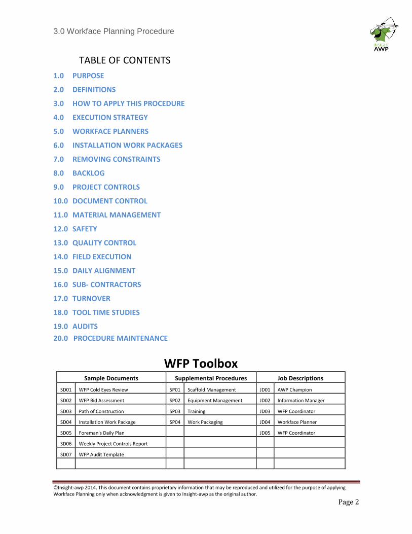
WFP Toolbox Sample Documents Supplemental Procedures Job Descriptions
SD01 WFP Cold Eyes Review SP01 Scaffold Management JD01 AWP Champion
SD02 WFP Bid Assessment SP02 Equipment Management JD02 Information Manager
SD03 Path of Construction SP03 Training JD03 WFP Coordinator
SD04 Installation Work Package SP04 Work Packaging JD04 Workface Planner
SD05 Foreman's Daily Plan JD05 WFP Coordinator
SD06 Weekly Project Controls Report
SD07 WFP Audit Template
3.0 Workface Planning Procedure
©Insight-awp 2014, This document contains proprietary information that may be reproduced and utilized for the purpose of applying Workface Planning only when acknowledgment is given to Insight-awp as the original author.
Page 3
1. PURPOSE
The purpose of this document is to define the COMPANY expectations for the application of WFP (WFP) by the Construction Contractor. This document will guide the development and implementation of the process by the Construction Contractor and will then be used periodically to audit the application for compliance.
Objectives
The ultimate goal of WFP and the application of WFP software is to optimize construction execution through enhanced preparation and detailed planning.
Scope
This document will address
• The contractual obligations of the Construction Contractor to apply WFP.
• The development and population of the WFP organization chart
• The implementation of a standard for Installation Work Packages (IWPs)
• The application and utilization of WFP software.
• The process of constraint removal
• The interaction of Schedule and Planned Value with WFP
• The deliverables from the document control process to WFP
• The interaction between the material management process and WFP
• The process of QC and Safety facilitation through IWPs
• The field level execution process
Other procedures in this series will address:
• Project Management: ➢ The Path of Construction ➢ Alignment of EWPs with procurement and CWPs ➢ The size, content and sequence of EWPs
• Information Management: ➢ The design of the WBS ➢ Standards for data generation and WFP Software
• Training
• Scaffold Management
• Construction Equipment Management
Method
The WFP Coordinator is responsible to support the Construction Contractor’s execution of this procedure.
3.0 Workface Planning Procedure
©Insight-awp 2014, This document contains proprietary information that may be reproduced and utilized for the purpose of applying Workface Planning only when acknowledgment is given to Insight-awp as the original author.
Page 4
2 DEFINITIONS
• Workface: Is that geographic point where labor converts materials into a facility.
• Workface Planning: The process of organizing and delivering all the elements necessary, prior to the commencement of work, to enable labor to perform quality work in a safe, effective, and efficient manner.
• Workface Planner: A dedicated construction planner who has hands on construction skills and experience as a supervisor. Responsible for developing IWPs and removing constraints, reports directly to the construction superintendent.
• Workface Planning Coordinator: Owners representative who reports directly to the AWP Champion. Responsible to manage Contractor’s WFP department, coordinate the turnover of CWPs form the Construction Management Team to the Contractors, and oversee the function of IWP development and constraint management.
• Information Manager: Owner’s representative who reports directly to the AWP Champion. Responsible to develop systems and processes that govern the generation and transfer of project information. Responsible to facilitate the development of the project cloud with a document management system, material management database and Workface Planning software.
• AWP Champion: Owner’s representative and member of the Project Management Team, responsible for the application and oversight of AWP, IM and WFP by all of the Project Stakeholders.
• Labor: Skilled or unskilled trades people, craft workers, artisans or workforce, divided by discipline, who are responsible for the actual physical work that converts materials into facilities.
• Constraints: The Information, Tools, Materials, and Access that are required to execute work.
• Work Packaging: The progressive elaboration of work from Engineering Work Packages to Procurement Work Packages and Module Work Packages based upon the requirements of Construction Work Packages. Further dissected into Installation Work Package and then into Daily Plans. The sequence of work dissection follows the path identified in the Path of Construction with the components modeled upon the structure of the WBS.
• Owner: The COMPANY that initiates a project by developing a business requirement.
• Project Management Team: A division of the COMPANY who are responsible to synchronize and manage Engineering, Procurement and Construction for the entire life cycle of the project.
• Engineering: Includes COMPANY Engineering and a series of specialized engineering companies who report directly to the Engineering Manager who is a member of the PMT. Engineering are responsible to elaborate the owner’s concepts into a detailed design. This organization is directly responsible for the functionality of the process and the generation of project information.
• Procurement: The procurement division of the PMT or a division of the Engineering Team. This team is responsible to engage contractors and suppliers, fabricators, module assembly yards and construction contractors through the development of contracts. Also responsible to manage the procurement of bulk materials, components and oversee the fabrication and delivery of equipment, pipe and steel components.
3.0 Workface Planning Procedure
©Insight-awp 2014, This document contains proprietary information that may be reproduced and utilized for the purpose of applying Workface Planning only when acknowledgment is given to Insight-awp as the original author.
Page 5
• Material Management: The organization who are responsible for receiving all project material from the procurement team. Responsible to manage onsite warehousing and the distribution of all site materials.
• Construction Contractor: The organization engaged to construct the project utilizing direct hire labor and subcontractors.
• Discipline: A unique trade identified as: Civil, Structural Steel, Pipe, Mechanical, Electrical, Instrumentation or insulation etc.
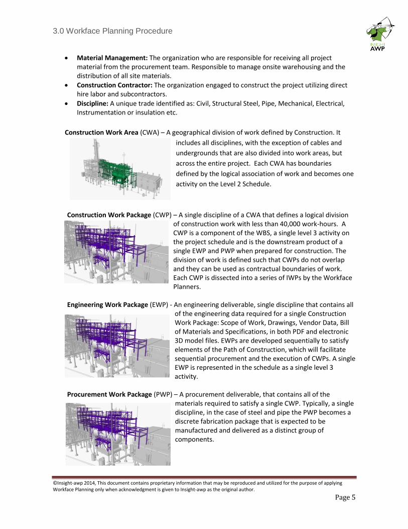
Construction Work Area (CWA) – A geographical division of work defined by Construction. It
includes all disciplines, with the exception of cables and
undergrounds that are also divided into work areas, but
across the entire project. Each CWA has boundaries
defined by the logical association of work and becomes one
activity on the Level 2 Schedule.
Construction Work Package (CWP) – A single discipline of a CWA that defines a logical division of construction work with less than 40,000 work-hours. A CWP is a component of the WBS, a single level 3 activity on the project schedule and is the downstream product of a single EWP and PWP when prepared for construction. The division of work is defined such that CWPs do not overlap and they can be used as contractual boundaries of work. Each CWP is dissected into a series of IWPs by the Workface Planners.
Engineering Work Package (EWP) - An engineering deliverable, single discipline that contains all
of the engineering data required for a single Construction Work Package: Scope of Work, Drawings, Vendor Data, Bill of Materials and Specifications, in both PDF and electronic 3D model files. EWPs are developed sequentially to satisfy elements of the Path of Construction, which will facilitate sequential procurement and the execution of CWPs. A single EWP is represented in the schedule as a single level 3 activity.
Procurement Work Package (PWP) – A procurement deliverable, that contains all of the
materials required to satisfy a single CWP. Typically, a single discipline, in the case of steel and pipe the PWP becomes a discrete fabrication package that is expected to be manufactured and delivered as a distinct group of components.
3.0 Workface Planning Procedure
©Insight-awp 2014, This document contains proprietary information that may be reproduced and utilized for the purpose of applying Workface Planning only when acknowledgment is given to Insight-awp as the original author.
Page 6
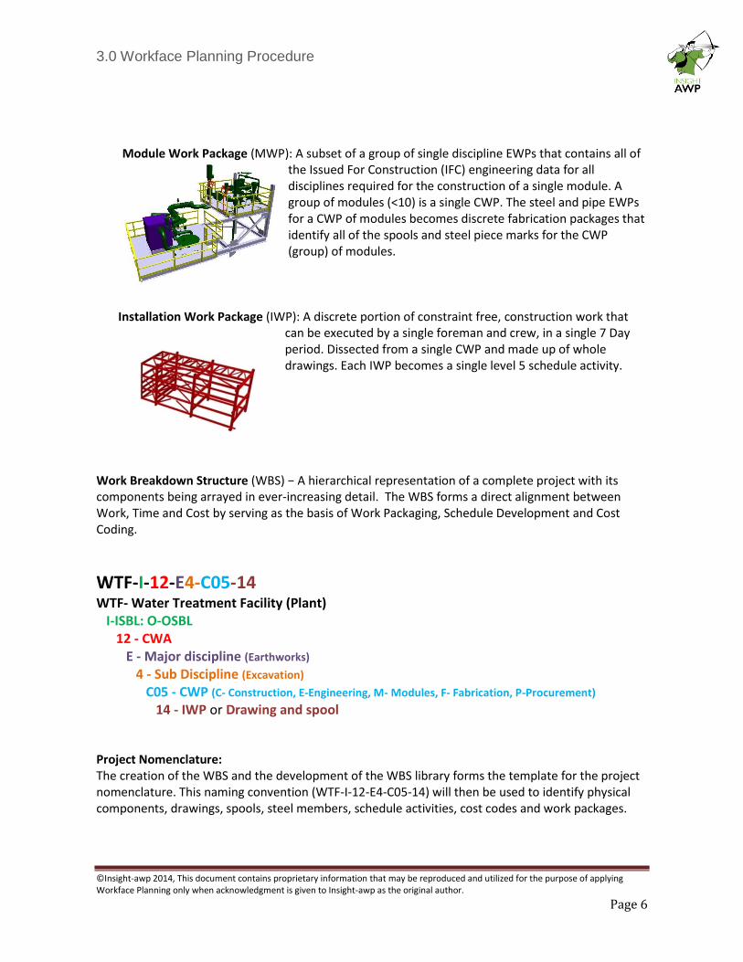
Module Work Package (MWP): A subset of a group of single discipline EWPs that contains all of
the Issued For Construction (IFC) engineering data for all disciplines required for the construction of a single module. A group of modules (<10) is a single CWP. The steel and pipe EWPs for a CWP of modules becomes discrete fabrication packages that identify all of the spools and steel piece marks for the CWP (group) of modules.
Installation Work Package (IWP): A discrete portion of constraint free, construction work that
can be executed by a single foreman and crew, in a single 7 Day period. Dissected from a single CWP and made up of whole drawings. Each IWP becomes a single level 5 schedule activity.
Work Breakdown Structure (WBS) − A hierarchical representation of a complete project with its components being arrayed in ever-increasing detail. The WBS forms a direct alignment between Work, Time and Cost by serving as the basis of Work Packaging, Schedule Development and Cost Coding.
WTF-I-12-E4-C05-14 WTF- Water Treatment Facility (Plant) I-ISBL: O-OSBL 12 - CWA E - Major discipline (Earthworks) 4 - Sub Discipline (Excavation)
C05 - CWP (C- Construction, E-Engineering, M- Modules, F- Fabrication, P-Procurement)
14 - IWP or Drawing and spool Project Nomenclature: The creation of the WBS and the development of the WBS library forms the template for the project nomenclature. This naming convention (WTF-I-12-E4-C05-14) will then be used to identify physical components, drawings, spools, steel members, schedule activities, cost codes and work packages.
3.0 Workface Planning Procedure
©Insight-awp 2014, This document contains proprietary information that may be reproduced and utilized for the purpose of applying Workface Planning only when acknowledgment is given to Insight-awp as the original author.
Page 7
Field Supervision: For the purpose of this procedure these terms are used to describe the three basic levels of field supervision that exist within the Construction Contractor or Subcontractor organizations. Ratios are expected to vary based upon the complexity and critical nature of the tasks. Terms and ratios may be changed to suit the local standards.
a. Foreman: Responsible for the direct supervision of one labor crew in a single discipline, with typically 1 foreman to 10 crew members.
b. General Foreman: Responsible to directly supervise up to 4 foremen in a single discipline.
c. Superintendent: Responsible to supervise up to 3 General Foremen in a single discipline. May be a member of staff or hired through the labor providers.
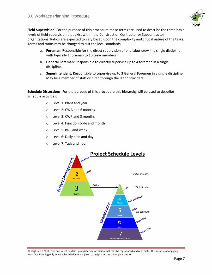
Schedule Dissections: For the purpose of this procedure this hierarchy will be used to describe schedule activities:
o Level 1: Plant and year
o Level 2: CWA and 6 months
o Level 3: CWP and 3 months
o Level 4: Function code and month
o Level 5: IWP and week
o Level 6: Daily plan and day
o Level 7: Task and hour
3.0 Workface Planning Procedure
©Insight-awp 2014, This document contains proprietary information that may be reproduced and utilized for the purpose of applying Workface Planning only when acknowledgment is given to Insight-awp as the original author.
Page 8
3 HOW TO APPLY THIS PROCEDURE
Project Management Team:
This procedure will be supplied to the prospective bidders as a component of the Request For
Proposal for all contract types.
Construction Contractor:
Bid documents that are issued in response to a RFP must include a notice of intent to satisfy
this procedure.
Contract language:
CONTRACTOR will participate in OWNER sponsored Workface Planning program for planning,
scheduling, and execution of all WORK. This program will require CONTRACTOR’s Project
Schedule be delineated to Level 3 consisting of Construction Work Packages (CWPs) and then to
Level 5 through the creation of Installation Work Packages (IWPs). CONTRACTOR will provide
resumes for qualified personnel as described in the Workface Planning documents. The
candidates will be interviewed by the Owner with the successful candidates assigned to the
project, reporting functionally to theOwner’s Workface Planning Coordinator. The number of
Workface Planners will be provided as indicated on the attached Workface Planner resource
loading chart. Associated costs will be shown on the proposal pricing form where specifically
indicated. CONTRACTOR will show craft and corresponding rates as listed in CONTRACTOR’s
current Work Agreement rate schedule applicable to supply personnel as required.
COMPANY reserves the right to periodically review this procedure and apply amendments
through the management of change process.
3.0 Workface Planning Procedure
©Insight-awp 2014, This document contains proprietary information that may be reproduced and utilized for the purpose of applying Workface Planning only when acknowledgment is given to Insight-awp as the original author.
Page 9
4 EXECUTION STRATEGY
The Owner’s WFP Coordinator will assist the construction contractor with the development of an Execution Strategy for the integration of WFP at least 30 days in advance of the commencement of any direct work. The high level plan will include execution plans for the development of a WFP department and the adoption of this procedure.
The Execution Strategy will include but not be limited to:
• The process for identifying, hiring and training Workface Planners
• The standard for an Installation Work Package
• A list of standard constraints and the process for constraint removal.
• An office/equipment/radio/phone plan for Workface Planners
• A procedure for Level 6 (daily) planning
• A process that creates the construction schedule from IWPs.
• A code of accounts that will allow progress to be mapped against CWPs
• A system for the daily collection, logging, and reporting of delays (Barrier Log).
• A plan that links scaffold erection to the IWPs.
• A WFP training plan for the whole organization.
• The schedule for mobilization.
The WFP execution strategy will then be submitted to the AWP Champion who will present the
document to the project management team for review and approval. The approved execution
plan will be rolled up into the construction execution plan and is expected to guide the
development of WFP by the construction contractor.
Prior to mobilization, the Construction Contractor (with support from the WFP Champion) will
conduct a WFP Roll Out for their own organization.
A template for the Execution Strategy is available in the WFP Toolbox: SD07
3.0 Workface Planning Procedure
©Insight-awp 2014, This document contains proprietary information that may be reproduced and utilized for the purpose of applying Workface Planning only when acknowledgment is given to Insight-awp as the original author.
Page 10
5 WORKFACE PLANNERS
The Construction Contractor will identify Workface Planners in their bid proposal and then deploy these positions upon contract award.
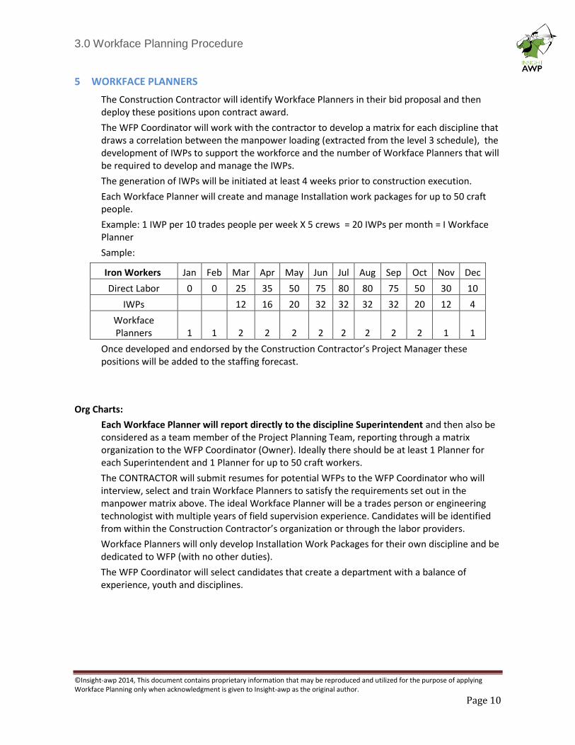
The WFP Coordinator will work with the contractor to develop a matrix for each discipline that draws a correlation between the manpower loading (extracted from the level 3 schedule), the development of IWPs to support the workforce and the number of Workface Planners that will be required to develop and manage the IWPs.
The generation of IWPs will be initiated at least 4 weeks prior to construction execution.
Each Workface Planner will create and manage Installation work packages for up to 50 craft people.
Example: 1 IWP per 10 trades people per week X 5 crews = 20 IWPs per month = I Workface Planner
Sample:
Once developed and endorsed by the Construction Contractor’s Project Manager these positions will be added to the staffing forecast.
Org Charts:
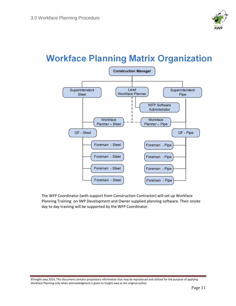
Each Workface Planner will report directly to the discipline Superintendent and then also be considered as a team member of the Project Planning Team, reporting through a matrix organization to the WFP Coordinator (Owner). Ideally there should be at least 1 Planner for each Superintendent and 1 Planner for up to 50 craft workers.
The CONTRACTOR will submit resumes for potential WFPs to the WFP Coordinator who will interview, select and train Workface Planners to satisfy the requirements set out in the manpower matrix above. The ideal Workface Planner will be a trades person or engineering technologist with multiple years of field supervision experience. Candidates will be identified from within the Construction Contractor’s organization or through the labor providers.
Workface Planners will only develop Installation Work Packages for their own discipline and be dedicated to WFP (with no other duties).
The WFP Coordinator will select candidates that create a department with a balance of experience, youth and disciplines.
Iron Workers Jan Feb Mar Apr May Jun Jul Aug Sep Oct Nov Dec
Direct Labor 0 0 25 35 50 75 80 80 75 50 30 10
IWPs 12 16 20 32 32 32 32 20 12 4
Workface Planners 1 1 2 2 2 2 2 2 2 2 1 1
3.0 Workface Planning Procedure
©Insight-awp 2014, This document contains proprietary information that may be reproduced and utilized for the purpose of applying Workface Planning only when acknowledgment is given to Insight-awp as the original author.
Page 11
The WFP Coordinator (with support from Construction Contractor) will set up Workface
Planning Training on IWP Development and Owner supplied planning software. Their onsite
day to day training will be supported by the WFP Coordinator.
3.0 Workface Planning Procedure
©Insight-awp 2014, This document contains proprietary information that may be reproduced and utilized for the purpose of applying Workface Planning only when acknowledgment is given to Insight-awp as the original author.
Page 12
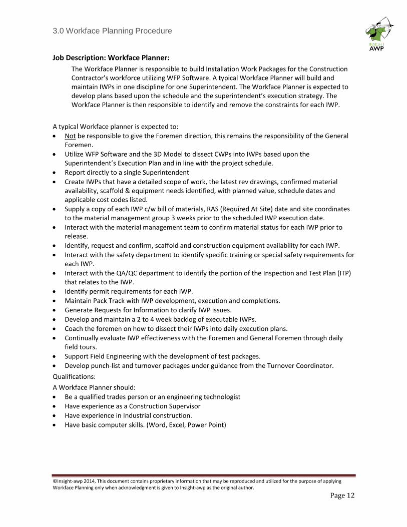
Job Description: Workface Planner:
The Workface Planner is responsible to build Installation Work Packages for the Construction Contractor’s workforce utilizing WFP Software. A typical Workface Planner will build and maintain IWPs in one discipline for one Superintendent. The Workface Planner is expected to develop plans based upon the schedule and the superintendent’s execution strategy. The Workface Planner is then responsible to identify and remove the constraints for each IWP.
A typical Workface planner is expected to:
• Not be responsible to give the Foremen direction, this remains the responsibility of the General Foremen.
• Utilize WFP Software and the 3D Model to dissect CWPs into IWPs based upon the Superintendent’s Execution Plan and in line with the project schedule.
• Report directly to a single Superintendent
• Create IWPs that have a detailed scope of work, the latest rev drawings, confirmed material availability, scaffold & equipment needs identified, with planned value, schedule dates and applicable cost codes listed.
• Supply a copy of each IWP c/w bill of materials, RAS (Required At Site) date and site coordinates to the material management group 3 weeks prior to the scheduled IWP execution date.
• Interact with the material management team to confirm material status for each IWP prior to release.
• Identify, request and confirm, scaffold and construction equipment availability for each IWP.
• Interact with the safety department to identify specific training or special safety requirements for each IWP.
• Interact with the QA/QC department to identify the portion of the Inspection and Test Plan (ITP) that relates to the IWP.
• Identify permit requirements for each IWP.
• Maintain Pack Track with IWP development, execution and completions.
• Generate Requests for Information to clarify IWP issues.
• Develop and maintain a 2 to 4 week backlog of executable IWPs.
• Coach the foremen on how to dissect their IWPs into daily execution plans.
• Continually evaluate IWP effectiveness with the Foremen and General Foremen through daily field tours.
• Support Field Engineering with the development of test packages.
• Develop punch-list and turnover packages under guidance from the Turnover Coordinator.
Qualifications:
A Workface Planner should:
• Be a qualified trades person or an engineering technologist
• Have experience as a Construction Supervisor
• Have experience in Industrial construction.
• Have basic computer skills. (Word, Excel, Power Point)
3.0 Workface Planning Procedure
©Insight-awp 2014, This document contains proprietary information that may be reproduced and utilized for the purpose of applying Workface Planning only when acknowledgment is given to Insight-awp as the original author.
Page 13
6 INSTALLATION WORK PACKAGES
The development of IWPs:
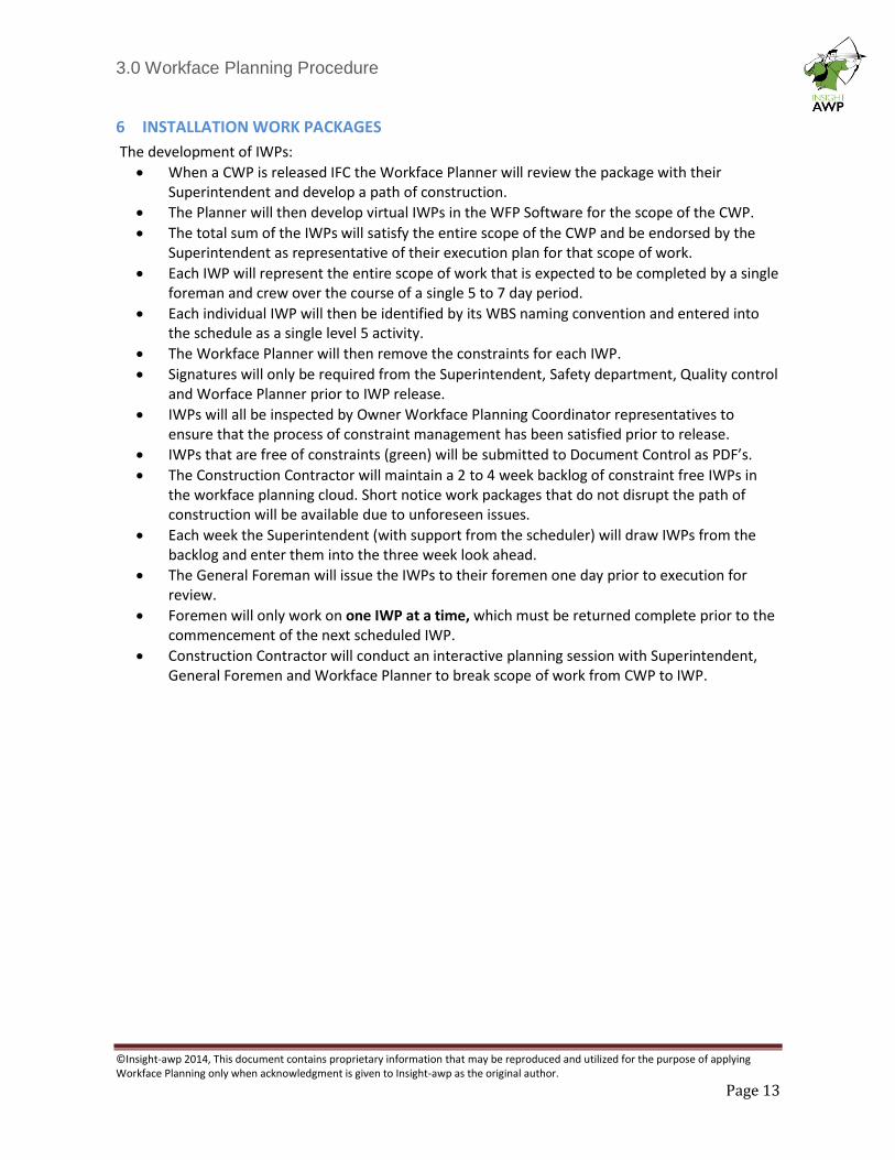
• When a CWP is released IFC the Workface Planner will review the package with their Superintendent and develop a path of construction.
• The Planner will then develop virtual IWPs in the WFP Software for the scope of the CWP.
• The total sum of the IWPs will satisfy the entire scope of the CWP and be endorsed by the Superintendent as representative of their execution plan for that scope of work.
• Each IWP will represent the entire scope of work that is expected to be completed by a single foreman and crew over the course of a single 5 to 7 day period.
• Each individual IWP will then be identified by its WBS naming convention and entered into the schedule as a single level 5 activity.
• The Workface Planner will then remove the constraints for each IWP.
• Signatures will only be required from the Superintendent, Safety department, Quality control and Worface Planner prior to IWP release.
• IWPs will all be inspected by Owner Workface Planning Coordinator representatives to ensure that the process of constraint management has been satisfied prior to release.
• IWPs that are free of constraints (green) will be submitted to Document Control as PDF’s.
• The Construction Contractor will maintain a 2 to 4 week backlog of constraint free IWPs in the workface planning cloud. Short notice work packages that do not disrupt the path of construction will be available due to unforeseen issues.
• Each week the Superintendent (with support from the scheduler) will draw IWPs from the backlog and enter them into the three week look ahead.
• The General Foreman will issue the IWPs to their foremen one day prior to execution for review.
• Foremen will only work on one IWP at a time, which must be returned complete prior to the commencement of the next scheduled IWP.
• Construction Contractor will conduct an interactive planning session with Superintendent, General Foremen and Workface Planner to break scope of work from CWP to IWP.
3.0 Workface Planning Procedure
©Insight-awp 2014, This document contains proprietary information that may be reproduced and utilized for the purpose of applying Workface Planning only when acknowledgment is given to Insight-awp as the original author.
Page 14
3.0 Workface Planning Procedure
©Insight-awp 2014, This document contains proprietary information that may be reproduced and utilized for the purpose of applying Workface Planning only when acknowledgment is given to Insight-awp as the original author.
Page 15
IWP Structure:
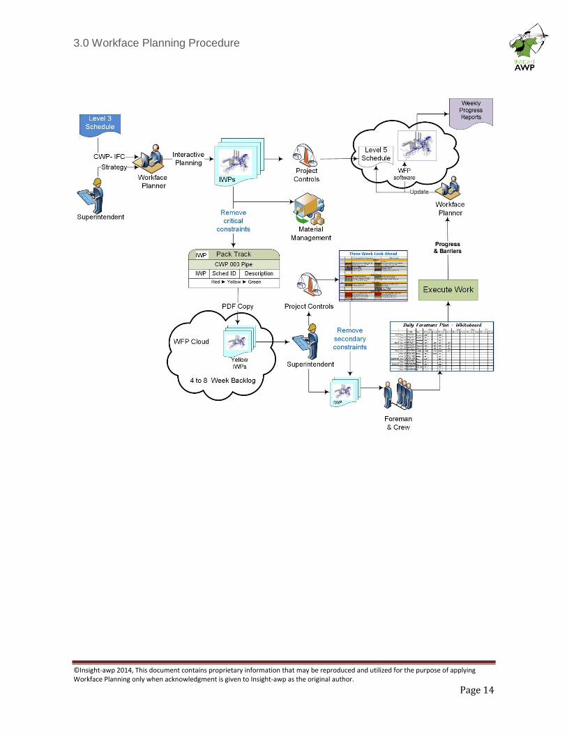
The content for each IWP must include:
• Cover Page: Shows 3-D snapshot or digital photo and a one-line description of the scope, the IWP number and the Planned Value in work-hours
• Inside Front Cover: Shows a plot plan of the site with emergency meeting points and assembly areas. Contains a complete list of emergency contact information.
• Constraints: Lists the constraints in order, showing the status of each with a sign-off column to show that the constraint has been removed.
• Scope: Two or three sentences that describe the scope followed by a list of risks (to achieving scope), mitigation strategies and assumptions.
• Safety: Single page of cut and pasted sections from the Job Hazard Analysis (overall plan) that is specific to the scope of the IWP. Followed by a section for a personal note from the safety representative that will help the foremen create a culture of safety. Populated and signed off by the safety representative.
• Quality: The portion of the Inspection and Test Plan (ITP) that is relevant to the scope, highlighted for the Foreman showing the required signatures, inspectors to be notified or holds that must be implemented.
• Documents: Complete list of all the relevant documents. All documents are added behind this page.
• Bill of Materials: A complete list of every component required for the IWP with a column for status. Also a copy of the Request for Material (inserted behind this page)
• Access: Pre-requisite work, Trade Coordination, Scaffold requests and Permits. Each section has details on how the constraint has been addressed.
• Construction Equipment: One page (from an equipment management database) showing the list of equipment requested and confirmation that the equipment will be ready for pick up or delivered to the site prior to starting the work.
• Cost and Delay Codes: A list of the cost codes that are specific to the work and a standard list of delay codes for tracking barriers.
• Progress: List of all quantities planned to be installed and their planned value with columns to claim progress and calculate earned value.
• Schedule: Single page that is a snapshot from the schedule or the three week look ahead, showing the IWP in relation to other IWPs.
• Completion: Shows that date that the IWP must be completed by, followed by sections for the foreman to use to record a punch list and lessons learned. Has sign off section for the Foreman.
3.0 Workface Planning Procedure
©Insight-awp 2014, This document contains proprietary information that may be reproduced and utilized for the purpose of applying Workface Planning only when acknowledgment is given to Insight-awp as the original author.
Page 16
7 REMOVING CONSTRAINTS
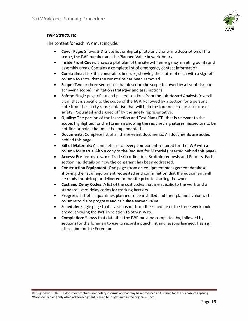
The Workface Planner is responsible to initially generate the list of constraints for each IWP based upon known obstacles.
Each IWP is assumed to have the following constraints, which must be removed for the IWP to be executable:
• CWP must be Issued for Construction, (IFC)
• Schedule must be aligned with the project plan
• Materials must be identified and confirmed onsite
• Prerequisite work that must be completed before the IWP can be executed
• Scaffold must be identified, ordered, and built fit-for-purpose
• Quality documentation (Inspection and Test Plans, installation manuals, specifications) must be available.
• Safety planning documents (JHA) that support the foreman’s safe application of the work must be available.
• Construction equipment must be identified and confirmed fit-for-purpose
• Clear access to a reliable supply of the right tools
• Resources (Qualified Trades) have been identified and confirmed available.
• Access to the workface has been confirmed, through the identification of permits and other trades that may be in close proximity
The IWP will travel through a series of stages of development that will be regulated by the
removal of these constraints. As each constraint is satisfied the IWP progresses to the next
stage until the IWP is free of constraints and executable.
3.0 Workface Planning Procedure
©Insight-awp 2014, This document contains proprietary information that may be reproduced and utilized for the purpose of applying Workface Planning only when acknowledgment is given to Insight-awp as the original author.
Page 17
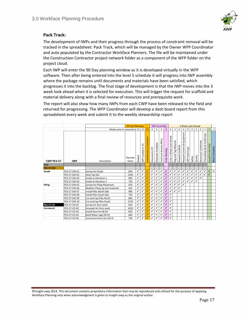
Pack Track:
The development of IWPs and their progress through the process of constraint removal will be tracked in the spreadsheet: Pack Track, which will be managed by the Owner WFP Coordinator and auto populated by the Contractor Workface Planners. The file will be maintained under the Construction Contractor project network folder as a component of the WFP folder on the project cloud.
Each IWP will enter the 90 Day planning window as it is developed virtually in the WFP software. Then after being entered into the level 5 schedule it will progress into IWP assembly where the package remains until documents and materials have been satisfied, which progresses it into the backlog. The final stage of development is that the IWP moves into the 3 week look ahead when it is selected for execution. This will trigger the request for scaffold and material delivery along with a final review of resources and prerequisite work.
The report will also show how many IWPs from each CWP have been released to the field and returned for progressing. The WFP Coordinator will develop a dash board report from this spreadsheet every week and submit it to the weekly stewardship report
12 12 12 4 4 4 4 3 3 3 3 3 2 2 2 1 1 -1
CWP PE3-57 IWP Description
Planned
Value Sco
ped
IWP
Cre
ated
in 3
D
Inse
rted
into
L5
Sch
edu
le
Do
cum
ents
IFC
Mat
eria
ls A
vaila
ble
Tech
nic
al R
evie
w (
RFI
s)
Ente
r B
ackl
og
Ente
r 3
Wee
k Lo
ok
Ah
ead
Bag
an
d T
ag M
ater
ial
Req
ues
t Sc
affo
ld
Req
ues
t C
ran
es &
Eq
uip
men
t
IWP
Har
d C
op
y
Safe
ty
Qu
alit
y
Res
ou
rces
Co
nfi
rmed
Pre
ceed
ing
Wo
rk C
on
firm
ed
Issu
ed t
o t
he
Fiel
d
Wo
rk C
om
ple
te
Civil
PE3-57-EW
Grade PE3-57-EW-01 Survey for Grade 840 P P P P P P P P P P P P P P P P P P
PE3-57-EW-02 Strip Top Soil 1340 P P P P P P P P P P P P P P P P P
PE3-57-EW-03 Grade to Elevation 1 890 P P P P P P P P P P P P P P P
PE3-57-EW-04 Grade to Elevation 2 730 P P P P P P P P P P P P P P
Piling PE3-57-EW-05 Survey for Piling Placement 620 P P P P P P P P P P P
PE3-57-EW-06 Mobilize Piling rig and materials 450 P P P P P P P P P P
PE3-57-EW-07 Install Piles North Side 980 P P P P P P P P P P
PE3-57-EW-08 Install Piles South Side 730 P P P P P P P P
PE3-57-EW-09 Cut and Cap Piles North 860 P P P P P P P P
PE3-57-EW-10 Cut and Cap Piles South 1250 P P P P P P P P
PE3-57-CO PE3-57-CO-01 Survey for form work 820 P P P P P P P P
Formwork PE3-57-CO-02 Excavate for form work 1420 P P P P P P P P
PE3-57-CO-03 Install form for EB-43 850 P P P P P P P P
PE3-57-CO-04 Build Rebar cage EB-43 640 P P P P P P P P
PE3-57-CO-05 Construct Forms for CG3-9 790 P P P P P P P P
Weeks prior to execution
90 Day Planning IWP Assembly 3 Week Look Ahead
3.0 Workface Planning Procedure
©Insight-awp 2014, This document contains proprietary information that may be reproduced and utilized for the purpose of applying Workface Planning only when acknowledgment is given to Insight-awp as the original author.
Page 18
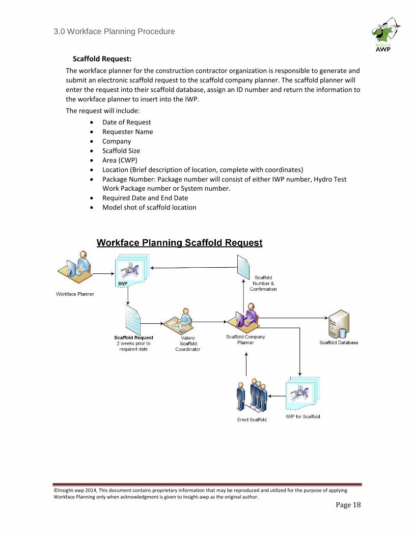
Scaffold Request:
The workface planner for the construction contractor organization is responsible to generate and
submit an electronic scaffold request to the scaffold company planner. The scaffold planner will
enter the request into their scaffold database, assign an ID number and return the information to
the workface planner to insert into the IWP.
The request will include:
• Date of Request
• Requester Name
• Company
• Scaffold Size
• Area (CWP)
• Location (Brief description of location, complete with coordinates)
• Package Number: Package number will consist of either IWP number, Hydro Test Work Package number or System number.
• Required Date and End Date
• Model shot of scaffold location
3.0 Workface Planning Procedure
©Insight-awp 2014, This document contains proprietary information that may be reproduced and utilized for the purpose of applying Workface Planning only when acknowledgment is given to Insight-awp as the original author.
Page 19
8 BACKLOG In order to maintain a consistent flow of work the construction contractors will establish and maintain a 2 to 4 week backlog of IWPs that are free of constraints. Superintendents will draw IWPs from the backlog and enter them into the three week look ahead, in line with the schedule and with consideration for the existing reality of the field. The backlog should also contain ‘Plan B’ work that can be activated at short notice for instances where an IWP must be stopped or pulled back from the field.
9 PROJECT CONTROLS
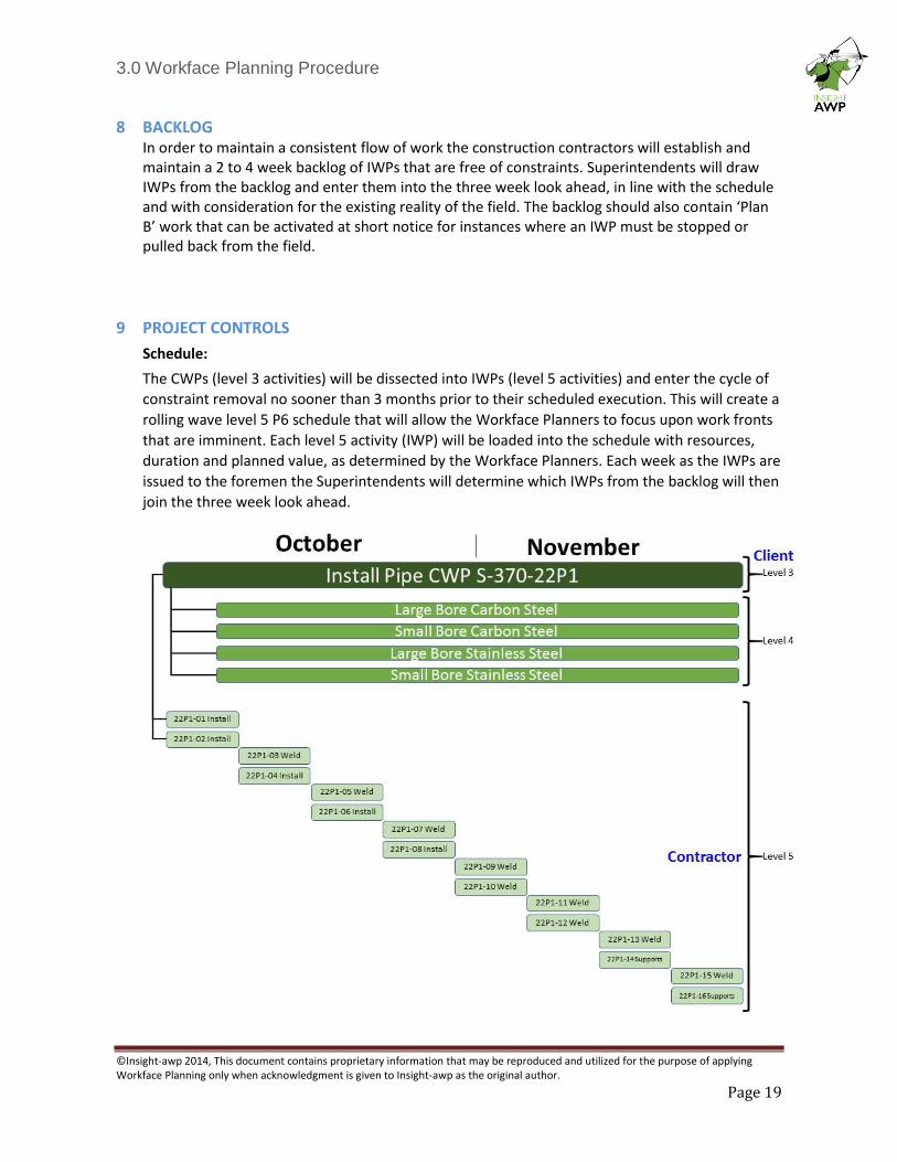
Schedule:
The CWPs (level 3 activities) will be dissected into IWPs (level 5 activities) and enter the cycle of
constraint removal no sooner than 3 months prior to their scheduled execution. This will create a
rolling wave level 5 P6 schedule that will allow the Workface Planners to focus upon work fronts
that are imminent. Each level 5 activity (IWP) will be loaded into the schedule with resources,
duration and planned value, as determined by the Workface Planners. Each week as the IWPs are
issued to the foremen the Superintendents will determine which IWPs from the backlog will then
join the three week look ahead.
3.0 Workface Planning Procedure
©Insight-awp 2014, This document contains proprietary information that may be reproduced and utilized for the purpose of applying Workface Planning only when acknowledgment is given to Insight-awp as the original author.
Page 20
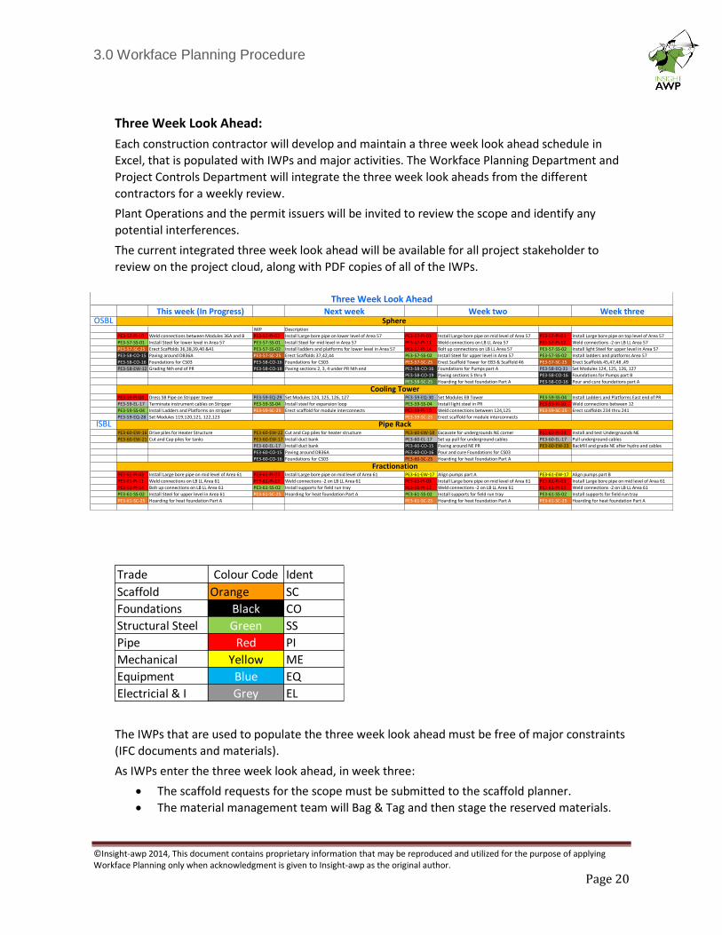
Three Week Look Ahead:
Each construction contractor will develop and maintain a three week look ahead schedule in
Excel, that is populated with IWPs and major activities. The Workface Planning Department and
Project Controls Department will integrate the three week look aheads from the different
contractors for a weekly review.
Plant Operations and the permit issuers will be invited to review the scope and identify any
potential interferences.
The current integrated three week look ahead will be available for all project stakeholder to
review on the project cloud, along with PDF copies of all of the IWPs.
The IWPs that are used to populate the three week look ahead must be free of major constraints
(IFC documents and materials).
As IWPs enter the three week look ahead, in week three:
• The scaffold requests for the scope must be submitted to the scaffold planner.
• The material management team will Bag & Tag and then stage the reserved materials.
Trade Colour Code Ident
Scaffold Orange SC
Foundations Black CO
Structural Steel Green SS
Pipe Red PI
Mechanical Yellow ME
Equipment Blue EQ
Electricial & I Grey EL
This week (In Progress) Next week Week two Week threeOSBL
IWP Description
PE3-57-PI-10 Weld connections between Modules 36A and B PE3-57-PI-02 Install Large bore pipe on lower level of Area 57 PE3-57-PI-03 Install Large bore pipe on mid level of Area 57 PE3-57-PI-03 Install Large bore pipe on top level of Area 57
PE3-57-SS-01 Install Steel for lower level in Area 57 PE3-57-SS-01 Install Steel for mid level in Area 57 PE3-57-PI-11 Weld connections on LB LL Area 57 PE3-57-PI-12 Weld connections -2 on LB LL Area 57
PE3-57-SC-25 Erect Scaffolds 36,38,39,40 &41 PE3-57-SS-02 Install ladders and platforms for lower level in Area 57 PE3-57-PI-14 Bolt up connections on LB LL Area 57 PE3-57-SS-02 Install light Steel for upper level in Area 57
PE3-58-CO-15 Paving around DB36A PE3-57-SC-25 Erect Scaffolds 37,42,44 PE3-57-SS-02 Install Steel for upper level in Area 57 PE3-57-SS-02 Install ladders and platforms Area 57
PE3-58-CO-16 Foundations for CS03 PE3-58-CO-16 Foundations for CS03 PE3-57-SC-25 Erect Scaffold Tower for EB3 & Scaffold 46 PE3-57-SC-25 Erect Scaffolds 45,47,48 ,49
PE3-58-EW-12 Grading Nth end of PR PE3-58-CO-18 Paving sections 2, 3, 4 under PR Nth end PE3-58-CO-16 Foundations for Pumps part A PE3-58-EQ-31 Set Modules 124, 125, 126, 127
PE3-58-CO-19 Paving sections 5 thru 9 PE3-58-CO-16 Foundations for Pumps part B
PE3-58-SC-25 Hoarding for heat foundation Part A PE3-58-CO-16 Pour and cure foundations part A
PE3-59-PI-04 Dress SB Pipe on Stripper tower PE3-59-EQ-29 Set Modules 124, 125, 126, 127 PE3-59-EQ-30 Set Modules EB Tower PE3-59-SS-04 Install Ladders and Platforms East end of PR
PE3-59-EL-17 Terminate instrument cables on Stripper PE3-59-SS-04 Install steel for expansion loop PE3-59-SS-04 Install light steel in PR PE3-59-PI-10 Weld connections between 12
PE3-59-SS-04 Install Ladders and Platforms on stripper PE3-59-SC-25 Erect scaffold for module interconnects PE3-59-PI-10 Weld connections between 124,125 PE3-59-SC-25 Erect scaffolds 234 thru 241
PE3-59-EQ-28 Set Modules 119,120,121, 122,123 PE3-59-SC-25 Erect scaffold for module interconnects
ISBLPE3-60-EW-16 Drive piles for Heater Structure PE3-60-EW-22 Cut and Cap piles for heater structure PE3-60-EW-18 Excavate for undergrounds NE corner PE3-60-PI-04 Install and test Undergrounds NE
PE3-60-EW-21 Cut and Cap piles for tanks PE3-60-EW-17 Install duct bank PE3-60-EL-17 Set up pull for underground cables PE3-60-EL-17 Pull underground cables
PE3-60-EL-17 Install duct bank PE3-60-CO-15 Paving around NE PR PE3-60-EW-23 Backfill and grade NE after hydro and cables
PE3-60-CO-15 Paving around DB36A PE3-60-CO-16 Pour and cure Foundations for CS03
PE3-60-CO-16 Foundations for CS03 PE3-60-SC-25 Hoarding for heat foundation Part A
PE3-61-PI-03 Install Large bore pipe on mid level of Area 61 PE3-61-PI-03 Install Large bore pipe on mid level of Area 61 PE3-61-EW-17 Align pumps part A PE3-61-EW-17 Align pumps part B
PE3-61-PI-11 Weld connections on LB LL Area 61 PE3-61-PI-12 Weld connections -2 on LB LL Area 61 PE3-61-PI-03 Install Large bore pipe on mid level of Area 61 PE3-61-PI-03 Install Large bore pipe on mid level of Area 61
PE3-61-PI-14 Bolt up connections on LB LL Area 61 PE3-61-SS-02 Install supports for field run tray PE3-61-PI-12 Weld connections -2 on LB LL Area 61 PE3-61-PI-12 Weld connections -2 on LB LL Area 61
PE3-61-SS-02 Install Steel for upper level in Area 61 PE3-61-SC-25 Hoarding for heat foundation Part A PE3-61-SS-02 Install supports for field run tray PE3-61-SS-02 Install supports for field run tray
PE3-61-SC-25 Hoarding for heat foundation Part A PE3-61-SC-25 Hoarding for heat foundation Part A PE3-61-SC-25 Hoarding for heat foundation Part A
Three Week Look Ahead
Fractionation
Pipe Rack
Cooling Tower
Sphere
3.0 Workface Planning Procedure
©Insight-awp 2014, This document contains proprietary information that may be reproduced and utilized for the purpose of applying Workface Planning only when acknowledgment is given to Insight-awp as the original author.
Page 21
Planned Value: The construction contractor’s project controls department will support WFP and the generation of IWPs by providing the installation unit rates and rules of credit for all commodities. The matrix will then be entered into the WFP Software where it will be utilized by the Workface Planners to generate planned value for Steel and Pipe IWPs. The Contractor’s Project Controls department will manually generate planned value for IWPs in other disciplines.
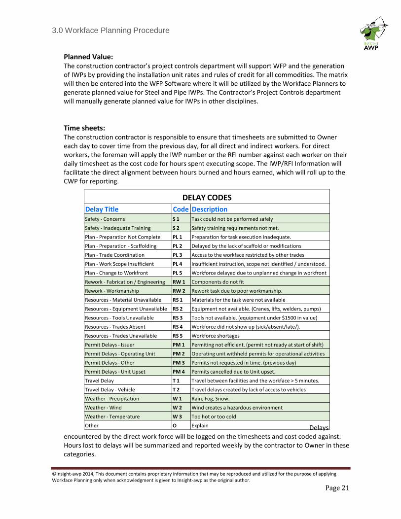
Time sheets: The construction contractor is responsible to ensure that timesheets are submitted to Owner each day to cover time from the previous day, for all direct and indirect workers. For direct workers, the foreman will apply the IWP number or the RFI number against each worker on their daily timesheet as the cost code for hours spent executing scope. The IWP/RFI Information will facilitate the direct alignment between hours burned and hours earned, which will roll up to the CWP for reporting.
Delays encountered by the direct work force will be logged on the timesheets and cost coded against: Hours lost to delays will be summarized and reported weekly by the contractor to Owner in these categories.
Delay Title Code DescriptionSafety - Concerns S 1 Task could not be performed safely
Safety - Inadequate Training S 2 Safety training requirements not met.
Plan - Preparation Not Complete PL 1 Preparation for task execution inadequate.
Plan - Preparation - Scaffolding PL 2 Delayed by the lack of scaffold or modifications
Plan - Trade Coordination PL 3 Access to the workface restricted by other trades
Plan - Work Scope Insufficient PL 4 Insufficient instruction, scope not identified / understood.
Plan - Change to Workfront PL 5 Workforce delayed due to unplanned change in workfront
Rework - Fabrication / Engineering RW 1 Components do not fit
Rework - Workmanship RW 2 Rework task due to poor workmanship.
Resources - Material Unavailable RS 1 Materials for the task were not available
Resources - Equipment Unavailable RS 2 Equipment not available. (Cranes, lifts, welders, pumps)
Resources - Tools Unavailable RS 3 Tools not available. (equipment under $1500 in value)
Resources - Trades Absent RS 4 Workforce did not show up (sick/absent/late/).
Resources - Trades Unavailable RS 5 Workforce shortages
Permit Delays - Issuer PM 1 Permiting not efficient. (permit not ready at start of shift)
Permit Delays - Operating Unit PM 2 Operating unit withheld permits for operational activities
Permit Delays - Other PM 3 Permits not requested in time. (previous day)
Permit Delays - Unit Upset PM 4 Permits cancelled due to Unit upset.
Travel Delay T 1 Travel between facilities and the workface > 5 minutes.
Travel Delay - Vehicle T 2 Travel delays created by lack of access to vehicles
Weather - Precipitation W 1 Rain, Fog, Snow.
Weather - Wind W 2 Wind creates a hazardous environment
Weather - Temperature W 3 Too hot or too cold
Other O Explain
DELAY CODES
3.0 Workface Planning Procedure
©Insight-awp 2014, This document contains proprietary information that may be reproduced and utilized for the purpose of applying Workface Planning only when acknowledgment is given to Insight-awp as the original author.
Page 22
Progress: Progress will be recorded by the Foremen directly in their IWP and reported each day to the Workface Planners, who will enter progress into the Workface Planning software. The construction contractor may also elect to record the same progress in their own software. The construction contractor superintendents or project controls team is expected to validate installed quantities weekly before the progress is rolled up against CWPs and reported in the weekly stewardship report. The workface planners, with support from the WFP Coordinator will draw progress from the Workface Planning software against each CWP for the purpose of weekly stewardship reporting.
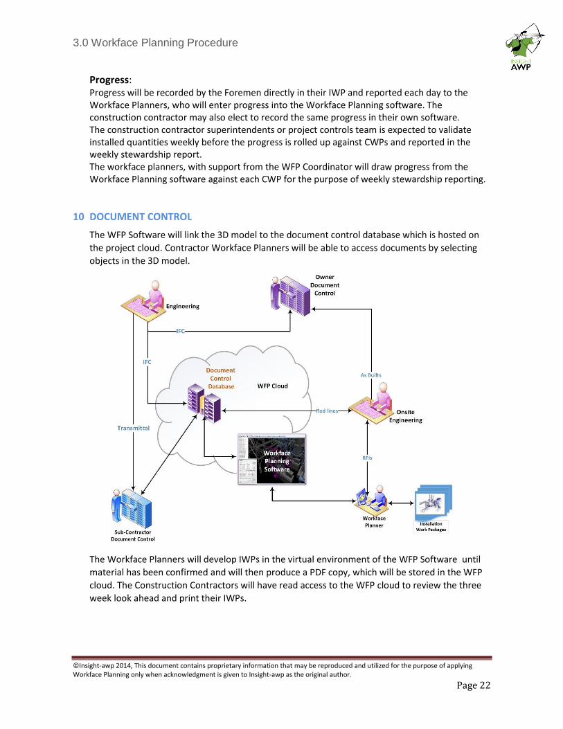
10 DOCUMENT CONTROL
The WFP Software will link the 3D model to the document control database which is hosted on
the project cloud. Contractor Workface Planners will be able to access documents by selecting
objects in the 3D model.
The Workface Planners will develop IWPs in the virtual environment of the WFP Software until
material has been confirmed and will then produce a PDF copy, which will be stored in the WFP
cloud. The Construction Contractors will have read access to the WFP cloud to review the three
week look ahead and print their IWPs.
3.0 Workface Planning Procedure
©Insight-awp 2014, This document contains proprietary information that may be reproduced and utilized for the purpose of applying Workface Planning only when acknowledgment is given to Insight-awp as the original author.
Page 23
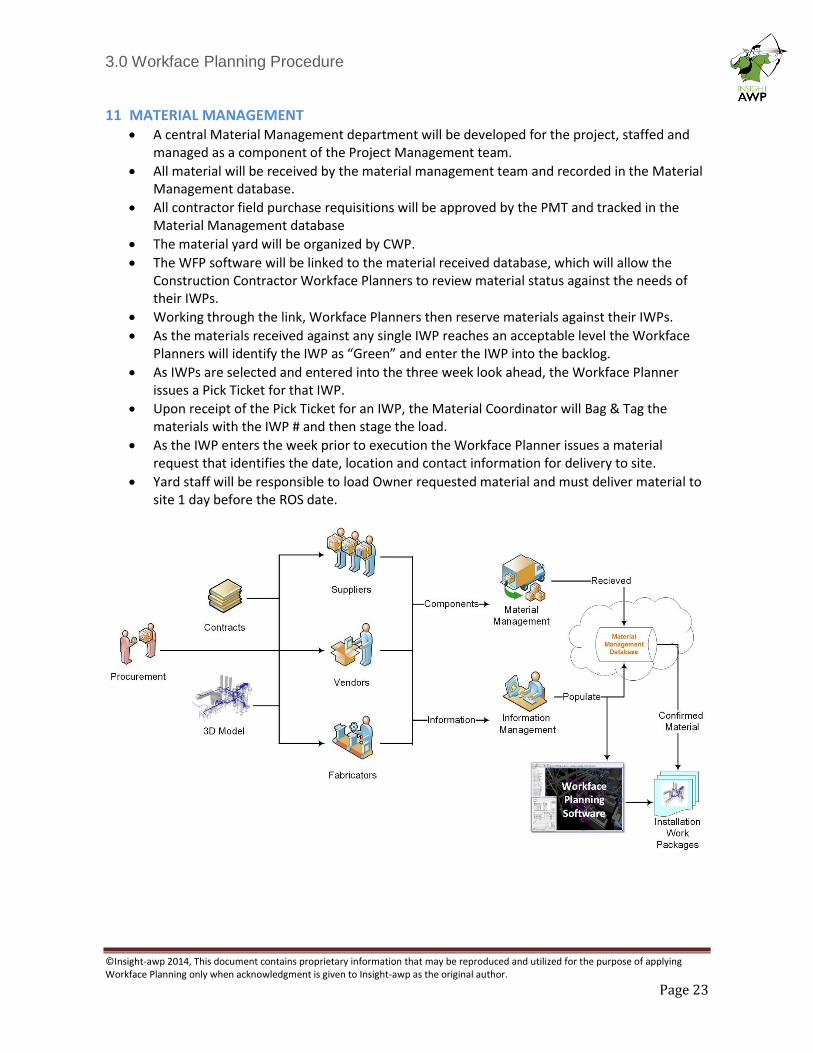
11 MATERIAL MANAGEMENT • A central Material Management department will be developed for the project, staffed and
managed as a component of the Project Management team.
• All material will be received by the material management team and recorded in the Material Management database.
• All contractor field purchase requisitions will be approved by the PMT and tracked in the Material Management database
• The material yard will be organized by CWP.
• The WFP software will be linked to the material received database, which will allow the Construction Contractor Workface Planners to review material status against the needs of their IWPs.
• Working through the link, Workface Planners then reserve materials against their IWPs.
• As the materials received against any single IWP reaches an acceptable level the Workface Planners will identify the IWP as “Green” and enter the IWP into the backlog.
• As IWPs are selected and entered into the three week look ahead, the Workface Planner issues a Pick Ticket for that IWP.
• Upon receipt of the Pick Ticket for an IWP, the Material Coordinator will Bag & Tag the materials with the IWP # and then stage the load.
• As the IWP enters the week prior to execution the Workface Planner issues a material request that identifies the date, location and contact information for delivery to site.
• Yard staff will be responsible to load Owner requested material and must deliver material to site 1 day before the ROS date.
3.0 Workface Planning Procedure
©Insight-awp 2014, This document contains proprietary information that may be reproduced and utilized for the purpose of applying Workface Planning only when acknowledgment is given to Insight-awp as the original author.
Page 24
12 SAFETY
In the normal course of execution each CWP will require a Job Hazard Analysis (JHA) that is generated by the Construction Contractor’s Safety Department or the General Foreman.
The Workface Planners will ensure that the JHA is utilized to support the IWP by extracting the pertinent pages and highlighting the passages that address the relative work scope for each IWP in the series.
The complete JHA along with the ITP will be issued as a single common attachment for all of the IWPs for a single CWP upon commencement of the scope.
Each individual IWP, with the JHA highlights, will be submitted to the safety department for review and signature as part of the constraint removal process.
The safety representative will ensure that the standard documentation is available to the foreman and will then review the scope and the JHA highlights for appropriateness.
The IWP will be utilized as a communication tool that supports the foreman’s obligation to create an environment that is free of known hazards.
Tools that support this initiative could include:
A printed safety talk that is pertinent to the scope
Some safety statistics that show trends based upon safety adherence.
As a notice board that announces a safety initiatives
The Workface Planners will support the optimization of this communication tool by working closely with the safety department during the development of this process.
Each IWP must be signed by a representative of the safety department to show that it has been reviewed.
13 QUALITY CONTROL
Each IWP will be submitted to the quality department for review and signature as part of the constraint removal process.
The quality control department will review the scope and then add only the pertinent sections of the Inspection and Test Plan (ITP) with highlights for quick reference.
Documents that must be completed to comply with the ITP will also be added with an instruction page that tells the foreman exactly what action is required.
The QC department is expected to utilize the IWP as a communication tool between QC and the Foreman by listing the Construction Contractors obligations under the agreement and also as a tool that supports the culture of quality.
This may be a printed quality talk that is pertinent to the scope or some quality statistics that show the benefit of quality adherence.
When the work is completed the general foreman will return the IWP to the Workface Planner who will remove any original QC documents, replace them with copies and then submit the originals the QC department.
The QC department will review the documents and correct any deficiencies directly with the foreman.
Each IWP must be signed by a representative of the Quality Control department to be considered free of this constraint.
3.0 Workface Planning Procedure
©Insight-awp 2014, This document contains proprietary information that may be reproduced and utilized for the purpose of applying Workface Planning only when acknowledgment is given to Insight-awp as the original author.
Page 25
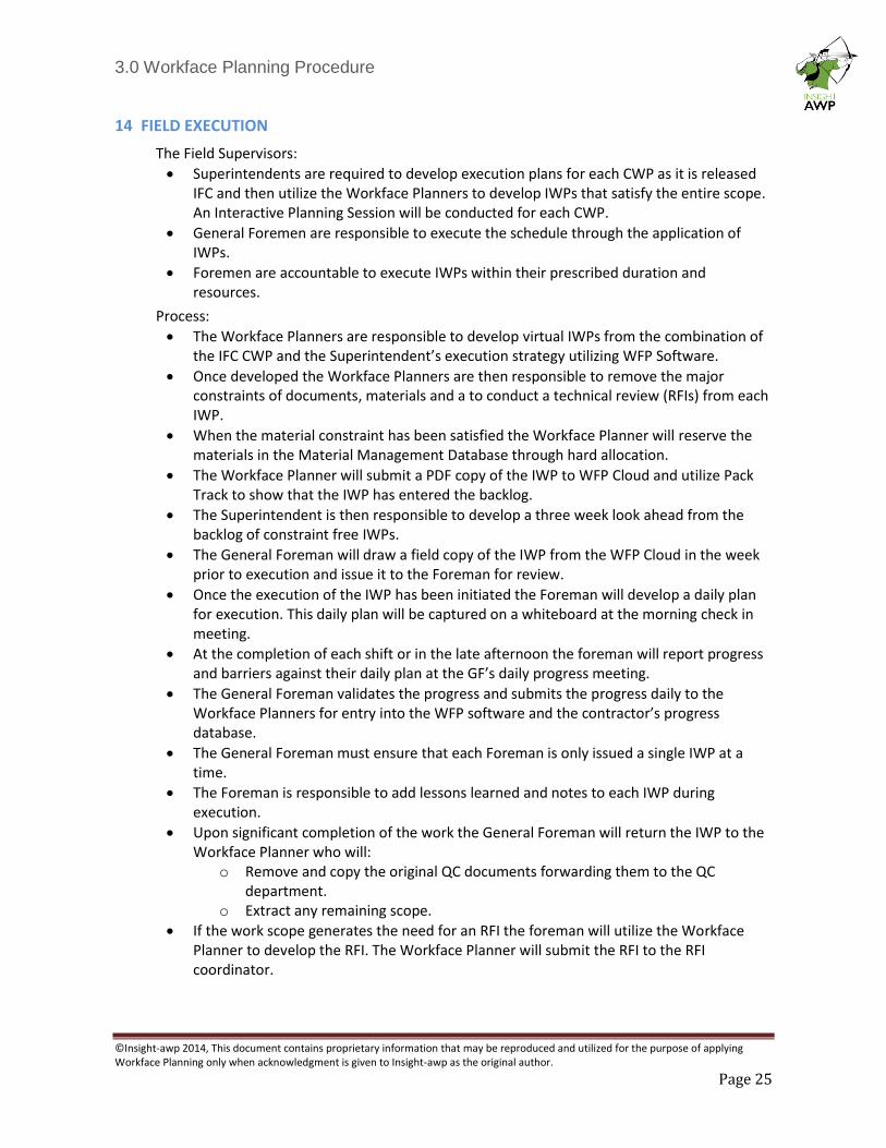
14 FIELD EXECUTION
The Field Supervisors:
• Superintendents are required to develop execution plans for each CWP as it is released IFC and then utilize the Workface Planners to develop IWPs that satisfy the entire scope. An Interactive Planning Session will be conducted for each CWP.
• General Foremen are responsible to execute the schedule through the application of IWPs.
• Foremen are accountable to execute IWPs within their prescribed duration and resources.
Process:
• The Workface Planners are responsible to develop virtual IWPs from the combination of the IFC CWP and the Superintendent’s execution strategy utilizing WFP Software.
• Once developed the Workface Planners are then responsible to remove the major constraints of documents, materials and a to conduct a technical review (RFIs) from each IWP.
• When the material constraint has been satisfied the Workface Planner will reserve the materials in the Material Management Database through hard allocation.
• The Workface Planner will submit a PDF copy of the IWP to WFP Cloud and utilize Pack Track to show that the IWP has entered the backlog.
• The Superintendent is then responsible to develop a three week look ahead from the backlog of constraint free IWPs.
• The General Foreman will draw a field copy of the IWP from the WFP Cloud in the week prior to execution and issue it to the Foreman for review.
• Once the execution of the IWP has been initiated the Foreman will develop a daily plan for execution. This daily plan will be captured on a whiteboard at the morning check in meeting.
• At the completion of each shift or in the late afternoon the foreman will report progress and barriers against their daily plan at the GF’s daily progress meeting.
• The General Foreman validates the progress and submits the progress daily to the Workface Planners for entry into the WFP software and the contractor’s progress database.
• The General Foreman must ensure that each Foreman is only issued a single IWP at a time.
• The Foreman is responsible to add lessons learned and notes to each IWP during execution.
• Upon significant completion of the work the General Foreman will return the IWP to the Workface Planner who will:
o Remove and copy the original QC documents forwarding them to the QC department.
o Extract any remaining scope.
• If the work scope generates the need for an RFI the foreman will utilize the Workface Planner to develop the RFI. The Workface Planner will submit the RFI to the RFI coordinator.
3.0 Workface Planning Procedure
©Insight-awp 2014, This document contains proprietary information that may be reproduced and utilized for the purpose of applying Workface Planning only when acknowledgment is given to Insight-awp as the original author.
Page 26
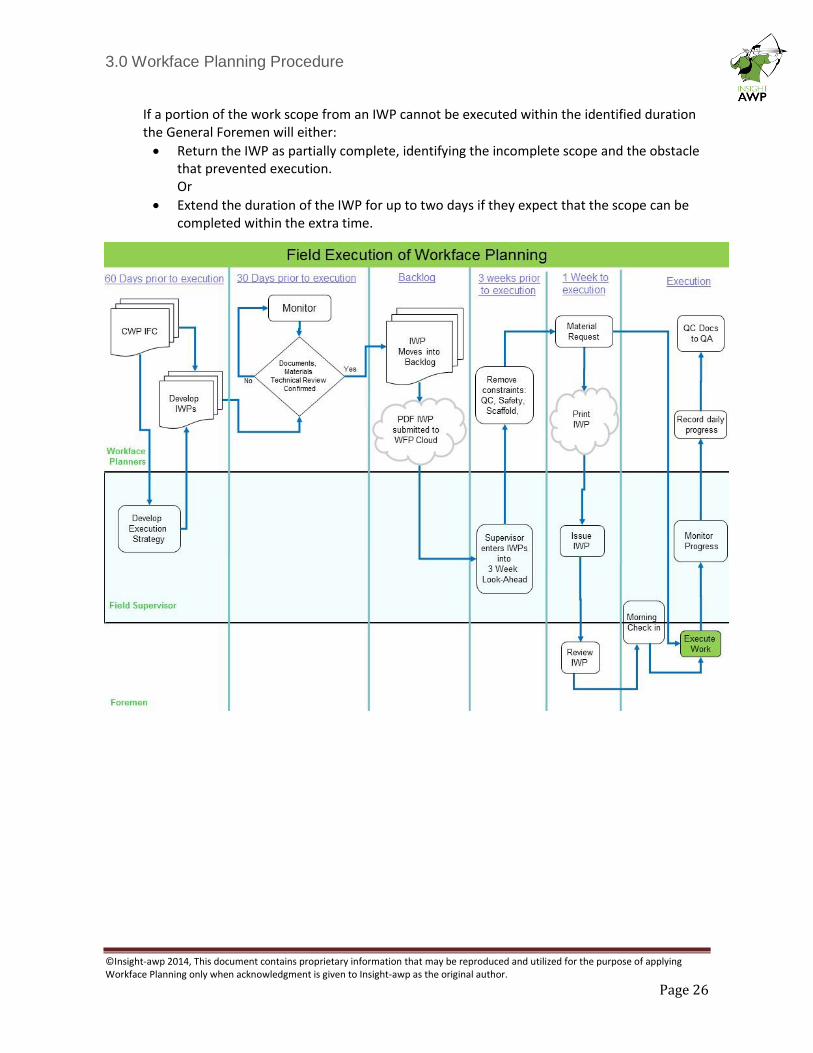
If a portion of the work scope from an IWP cannot be executed within the identified duration the General Foremen will either:
• Return the IWP as partially complete, identifying the incomplete scope and the obstacle that prevented execution. Or
• Extend the duration of the IWP for up to two days if they expect that the scope can be completed within the extra time.
3.0 Workface Planning Procedure
©Insight-awp 2014, This document contains proprietary information that may be reproduced and utilized for the purpose of applying Workface Planning only when acknowledgment is given to Insight-awp as the original author.
Page 27
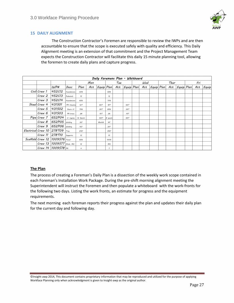
15 DAILY ALIGNMENT
The Construction Contractor’s Foremen are responsible to review the IWPs and are then
accountable to ensure that the scope is executed safely with quality and efficiency. This Daily
Alignment meeting is an extension of that commitment and the Project Management Team
expects the Construction Contractor will facilitate this daily 15 minute planning tool, allowing
the foremen to create daily plans and capture progress.
The Plan
The process of creating a Foreman’s Daily Plan is a dissection of the weekly work scope contained in
each Foreman’s Installation Work Package. During the pre-shift morning alignment meeting the
Superintendent will instruct the Foremen and then populate a whiteboard with the work-fronts for
the following two days. Listing the work fronts, an estimate for progress and the equipment
requirements.
The next morning each foreman reports their progress against the plan and updates their daily plan
for the current day and following day.
IWP# Desc Plan Act Equip Plan Act Equip Plan Act Equip Plan Act Equip Plan Act Equip
Civil Crew 1 452C12 Foundations 50% 65%
Crew 2 452C13 Pedastals 15 12
Crew 3 452C14 Foundations 65% 70%
Steel Crew 4 431S01 PR Cloumns 12T 65T 18T 65T
Crew 5 431S02 Stairs C1 75% 35T 85% 35T
Crew 6 431S03 PR brace 28 15T 26 15T
Pipe Crew 7 652P04 C! rigging 12 Spools 125T 8 spools 65T
Crew 8 652P05 Welding 32" Manlift 18"
Crew 9 652P06 Welding 42" 20"
Electrical Crew 10 278T09 Tray 245' 390'
Crew 11 278T10 Supports 12 10
Scaffold Crew 12 1009S76 Tower 65% 100%
Crew 13 1009S77 Mods, A12 12 A15
Crew 14 1009S78 PR 4 7
Mon Tue Wed Thur Fri
Daily Foremans Plan - Whitboard
3.0 Workface Planning Procedure
©Insight-awp 2014, This document contains proprietary information that may be reproduced and utilized for the purpose of applying Workface Planning only when acknowledgment is given to Insight-awp as the original author.
Page 28
16 SUB-CONTRACTORS
The Construction Contractor is responsible to ensure that all Sub-Contractors who report to the construction contractor develop and execute IWPs for all construction activities.
• All subcontractors are expected to engage their own Workface Planners and develop their own IWPs that roll up to form execution strategies that support the project’s overall flow of work.
• Subcontractor IWPs will follow the same development process and constraint removal process as outlined in this procedure for the Construction Contractor.
• The contractual requirement for WFP will be included in every sub-contract.
• If the scope of work is insufficient to hire and train a full time Workface Planner (<40,000hrs) then the Construction Contractor may support this activity with their own Workface Planners.
• If the sub-contractor IWPs are being developed by the Construction Contractor Workface Planners, then this process must be applied:
o The Sub-contractor superintendent must develop an execution plan (or several) that cover the entire scope of work.
o The sub-contractor superintendent will assume the position of a superintendent in the functional organization and give direction to the Workface Planner for the purpose of IWP development.
o The sub-contractor superintendent will endorse the IWPs and then utilize the Workface Planner to remove constraints, add the IWPs to the project schedule and record progress.
This supports the WFP fundamental that organizations develop their own IWPs based upon their own expertise, which allows them to retain ownership, control and accountability over their execution strategy and performance.
3.0 Workface Planning Procedure
©Insight-awp 2014, This document contains proprietary information that may be reproduced and utilized for the purpose of applying Workface Planning only when acknowledgment is given to Insight-awp as the original author.
Page 29
17 TURNOVER
The Workface Planners are expected to transition with the workforce from area construction to systems construction through the development of construction test packages (hydro-tests and loop checks). This will facilitate the turnover portion of the project and support mechanical completion. In order for this to take place, the discipline Superintendents will utilize the Workface Planners to build construction test packages to facilitate the testing portion of each project.
The parameters of the test packages will be based upon the designated turnover systems as determined by operations.
The Turnover coordinator will then utilize the Workface Planners and their resources to develop turnover packages.
A “preparation for turnover” IWP will contain:
• A summary description of the system being turned over (from the Turnover Coordinator)
• An extract from the WFP Software that shows the entire system and the current status/progress of each component (through color coding).
• A scheduled date for turnover
• A punch-list of scope that must be completed
• A complete list of the documents that will be required for turnover
• A flow chart that shows each stage of turnover
• A check sheet that shows the chronological list of activities, with provision for sign off at each stage.
The Turnover Coordinator may utilize the Workface Planners for the day to day administration of the packages, but it is ultimately the Turnover Coordinator themselves who is responsible to manage the execution of the packages thru to mechanical completion.
At the discretion of the commissioning and start-up team, the Workface Planners may be utilized to facilitate the coordination of their activities.
3.0 Workface Planning Procedure
©Insight-awp 2014, This document contains proprietary information that may be reproduced and utilized for the purpose of applying Workface Planning only when acknowledgment is given to Insight-awp as the original author.
Page 30
18 TOOL TIME STUDIES
In order to help track the effect of Workface Planning the construction management team will
initiate 3rd Party Tool Time studies at two/three month intervals throughout the project.
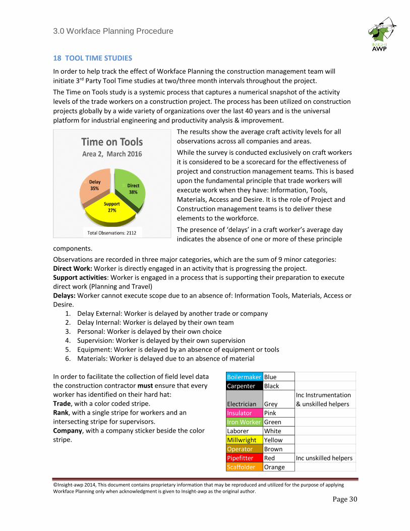
The Time on Tools study is a systemic process that captures a numerical snapshot of the activity
levels of the trade workers on a construction project. The process has been utilized on construction
projects globally by a wide variety of organizations over the last 40 years and is the universal
platform for industrial engineering and productivity analysis & improvement.
The results show the average craft activity levels for all
observations across all companies and areas.
While the survey is conducted exclusively on craft workers
it is considered to be a scorecard for the effectiveness of
project and construction management teams. This is based
upon the fundamental principle that trade workers will
execute work when they have: Information, Tools,
Materials, Access and Desire. It is the role of Project and
Construction management teams is to deliver these
elements to the workforce.
The presence of ‘delays’ in a craft worker’s average day
indicates the absence of one or more of these principle
components.
Observations are recorded in three major categories, which are the sum of 9 minor categories: Direct Work: Worker is directly engaged in an activity that is progressing the project. Support activities: Worker is engaged in a process that is supporting their preparation to execute direct work (Planning and Travel) Delays: Worker cannot execute scope due to an absence of: Information Tools, Materials, Access or Desire.
1. Delay External: Worker is delayed by another trade or company 2. Delay Internal: Worker is delayed by their own team 3. Personal: Worker is delayed by their own choice 4. Supervision: Worker is delayed by their own supervision 5. Equipment: Worker is delayed by an absence of equipment or tools 6. Materials: Worker is delayed due to an absence of material
In order to facilitate the collection of field level data the construction contractor must ensure that every worker has identified on their hard hat: Trade, with a color coded stripe. Rank, with a single stripe for workers and an intersecting stripe for supervisors. Company, with a company sticker beside the color stripe.
Boilermaker Blue
Carpenter Black
Electrician Grey
Inc Instrumentation
& unskilled helpers
Insulator Pink
Iron Worker Green
Laborer White
Millwright Yellow
Operator Brown
Pipefitter Red Inc unskilled helpers
Scaffolder Orange
3.0 Workface Planning Procedure
©Insight-awp 2014, This document contains proprietary information that may be reproduced and utilized for the purpose of applying Workface Planning only when acknowledgment is given to Insight-awp as the original author.
Page 31
19 AUDITS
In order to optimize the effectiveness of WFP, the WFP Coordinator will audit the process against this procedure at 6 month intervals with the initial review commencing no later than 3 months after mobilization.
The AWP Champion will then develop a schedule for periodic 3rd Party audits between these points. The Construction Contractor’s Construction Manager will facilitate access to the necessary personnel and information.
These audit points will appear in the master project schedule.
A Summary of the report will contain the following:
• Scorecard of adherence to this procedure as a % of total attainable
• A list of recommendations for alignment.
• Demographics of the project: Phase, Workforce and % Complete
• Comments and observations
• A list of acclamations and recommendations
The audits will utilize the COMPANY audit template from the WFP Toolbox: SD06
The results of the audits will be shared with the COMPANY AWP Champion for presentation to the Project Management Team, however the Construction Contractor is expected to develop and action their own tasks that address any deviations from the procedure.
20 PROCEDURE MAINTENANCE
This procedure is the first in a series of three core procedures that are interdependent to each other, therefore care should be taken that changes initiated here are not already covered in one of the other procedures or that the changes do not have a negative impact upon the effectiveness of the process as a whole. The local maintenance of this procedure is the responsibility of the AWP Champion over the course of the project and should reflect the reality of application, with optimizations of the process. At the completion of the project the AWP Champion is responsible to capture the actions taken by the project team to improve the procedure’s effectiveness.
This report should include a detailed list of:
• The audit results that show trends in conformance or diversions from the procedure.
• Changes made to the procedure during the project c/w with an explanation of the reason for the changes.
• Lesson learned captured at the end of the project phases from all stakeholders. Project Management end of project assessment that captures the effectiveness of the process and procedures.