Embed Size (px)
Citation preview
WORKFLOW - STRATUS AND SPECTRUM SURVEY
CONTENTS 1. Stratus Static (No Controller) 2. Stratus Static (Using Controller) 3. Stratus Kinematic (Stop-and-Go) Appendix A - Network Adjustments Appendix B – Obtaining an Almanac Appendix C – General Tips Appendix D – Sample Field Notes Form Appendix E – Antenna Measurement Methods
(Click on one of the above items to jump directly to that section.) PURPOSE The purpose of this document is to provide customers with additional information on using the Stratus GPS Survey System – including Spectrum Survey. The contents of this document include field and office procedures for three different methods (static, static with controller and kinematic) of using the system. The Appendix includes additional information concerning survey network adjustments.
Tplljb!Technical Support Kit 760-E-0013
Stratus Kit Introduction
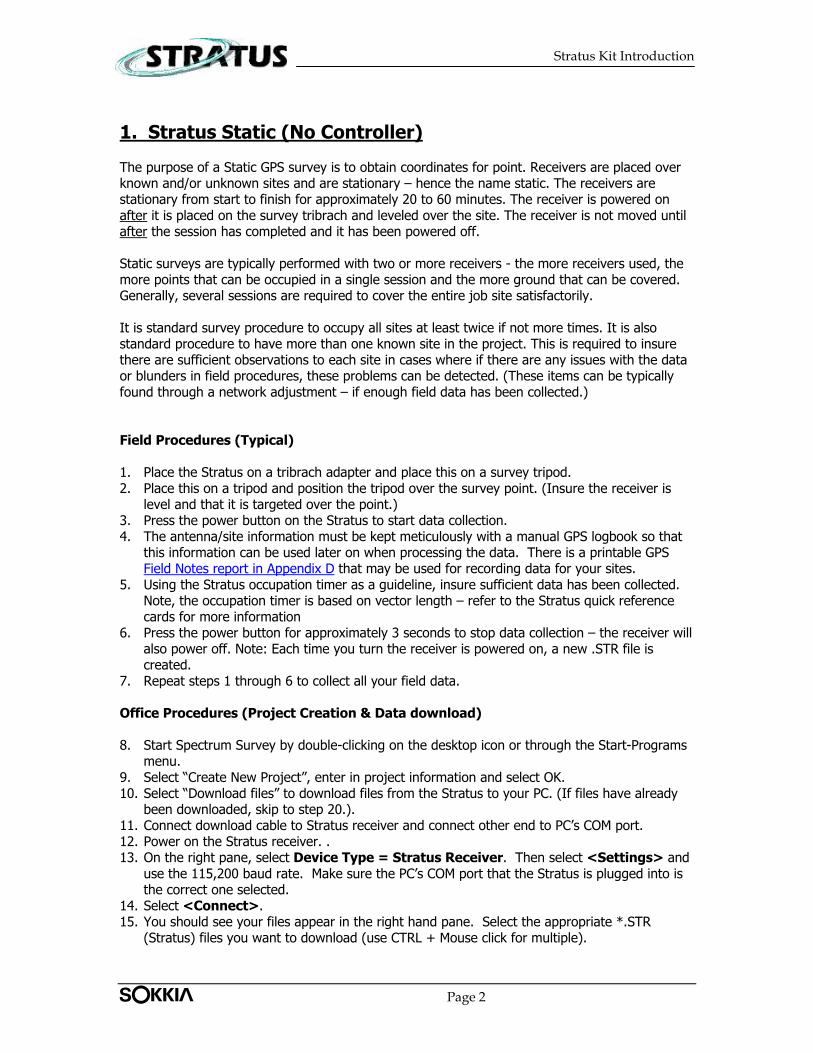
1. Stratus Static (No Controller) The purpose of a Static GPS survey is to obtain coordinates for point. Receivers are placed over known and/or unknown sites and are stationary – hence the name static. The receivers are stationary from start to finish for approximately 20 to 60 minutes. The receiver is powered on after it is placed on the survey tribrach and leveled over the site. The receiver is not moved until after the session has completed and it has been powered off. Static surveys are typically performed with two or more receivers - the more receivers used, the more points that can be occupied in a single session and the more ground that can be covered. Generally, several sessions are required to cover the entire job site satisfactorily. It is standard survey procedure to occupy all sites at least twice if not more times. It is also standard procedure to have more than one known site in the project. This is required to insure there are sufficient observations to each site in cases where if there are any issues with the data or blunders in field procedures, these problems can be detected. (These items can be typically found through a network adjustment – if enough field data has been collected.) Field Procedures (Typical) 1. Place the Stratus on a tribrach adapter and place this on a survey tripod. 2. Place this on a tripod and position the tripod over the survey point. (Insure the receiver is
level and that it is targeted over the point.) 3. Press the power button on the Stratus to start data collection. 4. The antenna/site information must be kept meticulously with a manual GPS logbook so that
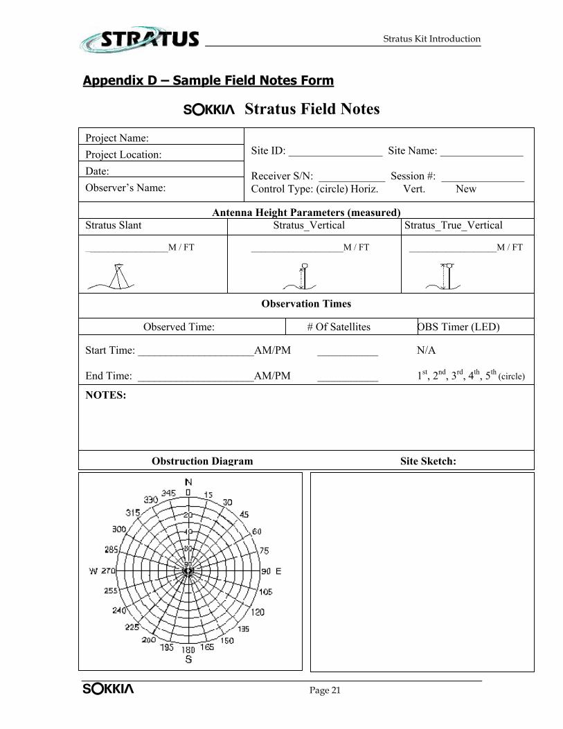
this information can be used later on when processing the data. There is a printable GPS Field Notes report in Appendix D that may be used for recording data for your sites.
5. Using the Stratus occupation timer as a guideline, insure sufficient data has been collected. Note, the occupation timer is based on vector length – refer to the Stratus quick reference cards for more information
6. Press the power button for approximately 3 seconds to stop data collection – the receiver will also power off. Note: Each time you turn the receiver is powered on, a new .STR file is created.
7. Repeat steps 1 through 6 to collect all your field data. Office Procedures (Project Creation & Data download) 8. Start Spectrum Survey by double-clicking on the desktop icon or through the Start-Programs
menu. 9. Select “Create New Project”, enter in project information and select OK. 10. Select “Download files” to download files from the Stratus to your PC. (If files have already
been downloaded, skip to step 20.). 11. Connect download cable to Stratus receiver and connect other end to PC’s COM port. 12. Power on the Stratus receiver. . 13. On the right pane, select Device Type = Stratus Receiver. Then select <Settings> and
use the 115,200 baud rate. Make sure the PC’s COM port that the Stratus is plugged into is the correct one selected.
14. Select <Connect>. 15. You should see your files appear in the right hand pane. Select the appropriate *.STR
(Stratus) files you want to download (use CTRL + Mouse click for multiple).
Tplljb! Page 2
Stratus Kit Introduction
16. Select the download path on the left-hand pane. Try to be consistent here and use the same directory structure. For example, after the project has been created, a project directory is created with a sub-directory labeled “data”; select this as the target path where you want files downloaded.
17. Press the arrow that is located in between the left and right panes – make sure the download direction is correct, i.e., from right to left.
18. The files will begin to download and a status bar will display the progress. 19. Repeat steps 8 through 19 for multiple Stratus receivers. Note: To avoid confusion, make
sure all your .STR files are downloaded to the same directory. Office Procedures (Data Import) 20. Next, the Data File Manager window should appear. (If not, select File-Data File Manager
from the menu.) 21. Select the Import button. 22. If the files have been downloaded to your project’s data directory, then they should appear
on screen. If you have downloaded files to a different location, navigate to that location. 23. Select the files you would like to import into your project. Stratus data files have a file suffix
of *.STR. (The CTRL and Shift can be used to select multiple files.) Note: If you are certain that the files are in the selected location and do not appear, make sure “Files of Type” reads: Sokkia.
24. Once all the files have been found and selected, press <Open>. 25. After import, you should now see all your files in the Data File Manager window. 26. Select <OK> to import the files into your project and display them in the plan view. 27. Warnings maybe presented on-screen for items such as: point proximity, etc… Carefully
review the warning messages. 28. The plan view should provide you with a fairly accurate display of all the points in the
project. 29. All vector combinations should automatically be generated and be visible on the plan view. If
vectors are not visible, insure that the correct files have been imported. Use the File-Data File Manager to check that the correct files have been imported and by checking the start time of each file to insure there is overlap. If vectors still are not visible, check that the vectors are set to be visible on the plan view by selecting the View menu and seeing if there is a checkmark next to Show Vectors. If this is ok, then go to Tools | Define Combinations. You may need to lower the minimum overlap value for Define Vectors from the default value based on your field occupation times. On some shorter occupations, this may be necessary.
Office Procedures (Coordinate System/Map Projection and Geoids) 30. At this time, choose Edit | Coordinate System and choose the map projection for your
local area. You can leave the default of geographic or change to a different map projection. If a map projection other than the predefined projections is required, choose <Add> and pick the desired projection – make sure all the correct projection parameters are entered. Otherwise, Spectrum Survey will not be able to generate the coordinates correctly. Also, on this screen, you are also able to change units between meters and feet. Note: Some projections have pre-defined templates with the datum and ellipsoid parameters already defined. If another projection is required, you will have to provide some additional information to create the system.
Tplljb! Page 3

Stratus Kit Introduction
31. Now, choose a geoid model if you would like to see orthometric heights (mean sea level heights). Select Edit | Geoid Model and choose the current model for your area and hit <OK>.
Office Procedures (Data Editing)
32. In the Plan View of Spectrum Survey, double click on one known point that you have
coordinates for. Key those coordinates in at this time and then check the box for “Use as GPS reference Coordinate” and hit <OK>. (Note, this not a must as Spectrum can assign a point automatically. In this case, coordinates of the points in your project will be based on this auto-assigned point and point coordinate values may not match values you already have for these points.)
33. From your field notes, you must enter in the instrument antenna heights for all points as well as selecting the antenna type. For Stratus, the antenna types are “Stratus_Vert” and “Stratus_Slant”. This can be performed either via Edit | Point or Select | Point. The Point editor enables viewing all related point information one point at a time while the Select point function enables viewing selected point information for all points simultaneously. Make sure that the antenna information is correct by reviewing it once the changes have been made.
Office Procedures (Data Processing) 34. Select Tools | Process Data to start data processing. Processing status will be displayed
on-screen. 35. Warnings maybe presented on-screen for items such as: antenna models, antenna heights,
point proximity, etc… The antenna information should have been entered in under a previous step. The point proximity warnings can be ignored if you know your points are close together.
36. After processing, you will be presented with a process summary. The goal here is to make sure your vectors are FIXED and that you have a high percentage of “Observations Used”. Low percentages indicate that many observations may have been rejected due to various reasons such as (multi-path, cycle slips, etc…). Note, if a problem is seen in the process summary, it is suggested that you look at the individual vector summary outputs for more information.
37. You can further investigate point information by going through the individual point summaries through Analysis | Processed Vectors | Vector Summary. You can flip through all the vector summaries or view selected vector summaries.
38. At this stage, if everything is ok, you can move on to the Network Adjustment (Appendix A).
Tplljb! Page 4
Stratus Kit Introduction
2. Stratus Static (with Controller) The purpose of a static survey is the same as listed under section 1. The only additional item here is the Stratus Controller; it is possible to store field notes such as point information or other notes on the data collector (iPAQ) instead paper copy field notes. Now instead of manually entering this information in the PC software (Spectrum Survey), it is automatically transferred from the iPAQ. Field Procedures (Typical) 1. Place the Stratus on a tribrach adapter and place this on a survey tripod. 2. Place this on a tripod and position the tripod over the survey point. (Insure the receiver is
level and that it is targeted over the point.) 3. Press the power button on the Stratus to start data collection. 4. Launch the Stratus Controller application on the field controller. 5. Select <Controller Setup> and ensure that the Distance Unit field is set appropriately
and the time reference is set to your local time system. For the Port setting, if you plan on using Infrared communications, set the option to “IrDA”. Select <OK> to leave the setup screen.
6. Select <Static Survey>. 7. Select <Add>. 8. For the Point ID field, key in the point id you want to assign to the point that is being
occupied. 9. Measure and then enter in the antenna height (Ant. Height) for this point. (Note: units
depend on Controller Setup options used.) 10. Select the appropriate antenna measurement method (Ant. Method). Choose one of the 3
available options: Slant, Vertical and True Vertical. (See Appendix E – Antenna Measurement Methods for more information.)
11. Enter in a point description (Desc) if you like. This is typically something descriptive that you can use to later on to recall point details. For example, “survey marker”, “edge of curb”, …etc. This field can be left alone if you do not want to enter in additional information.
12. The recording interval, Rec. Interval (sec), field is the data sampling rate, i.e., it refers to how often data is recorded on the receiver. Note: it is very important that this recording interval matches the recording interval for all other receivers being used in the survey. For static surveys, a recording interval of 10 seconds is sufficient.
13. The Elev. Mask (deg) field is used to modify the elevation mask of which satellites are tracked. Generally, satellite data lower than 5 degrees is noisier and more difficult to process. For static surveys, an elevation mask of 5 degrees is sufficient.
14. Select <Start> to begin your static observation. 15. Occupy the point until your occupation indicator LED is lit for your given baseline length (2,
5, 10, 15 or 20 km) between base and rover. (See Stratus User Manual for more information.)
16. Select <Receiver>, <Stop>. Then, decide which of the shutdown options you would like: • <End Job and Exit> - Stops the Job, but leaves receiver running. • <End Job, Shutdown Receiver and Exit> - Stops the job and powers down the
receiver, thus closing the file. • <Exit Without Ending Job> - Exits you out of this screen, but leaves the job active
and leaves the receiver running. • <Return to Survey> - Simply takes you back to your “Static Survey” logging screen.
(Basically a way back in if you somehow had to exit out of the static survey) 17. Repeat steps 7 to 14 to collect more static observations.
Tplljb! Page 5

Stratus Kit Introduction
Office Procedures (Project Creation & Data download) 18. Start Spectrum Survey by double-clicking on the desktop icon or through the Start-Programs
menu. 19. Select “Create New Project”, enter in project information and select OK. 20. Select “Download files” to download files from the Stratus to your PC. (If files have already
been downloaded, skip to step 39.). 21. Connect download cable to Stratus receiver and connect other end to PC’s COM port. 22. Power on the Stratus receiver. . 23. On the right pane, select Device Type = Stratus Receiver. Then select <Settings> and
use the 115,200 baud rate. Make sure the PC’s COM port that the Stratus is plugged into is the correct one selected.
24. Select <Connect>. 25. You should see your files appear in the right hand pane. Select the appropriate *.STR
(Stratus) files you want to download (use CTRL + Mouse click for multiple selections). 26. Select the download path on the left-hand pane. Try to be consistent here and use the same
directory structure. For example, after the project has been created, a project directory is created with a sub-directory labeled “data”; select this as the target path where you want files downloaded.
27. Press the arrow that is located in between the left and right panes – make sure the download direction is correct, i.e., from right to left.
28. The files will begin to download and a status bar will display the progress. 29. Repeat steps 21 through 27 for multiple Stratus receivers. Note: To avoid confusion, make
sure all your .STR files are downloaded to the same directory. Office Procedures (Data download – Controller Files)
30. Connect your handheld device to your PC using Microsoft Active Sync. 31. In Spectrum Survey, if you are not already in the download section, select File | Data File
Manager and from here, select <Download>. 32. On the right pane, select Device Type = Stratus Handheld. 33. Select <Connect>. All static controller files should be displayed. 34. Select the appropriate Stratus Controller Files (*.STA) files you want to download (use CTRL
+ Mouse click for multiple selections). 35. Select the download path on the left-hand pane. Be consistent with regards to the directory
location – use the same location as where the Stratus receiver files are located. For example, after the project has been created, a project directory is created with a sub-directory labeled “data”; select this as the target path where you want files downloaded.
36. Press the arrow that is located in between the left and right panes – make sure the download direction is correct, i.e., from right to left.
37. The files will begin to download and a status bar will display the progress. 38. Repeat steps 29 through 37 for multiple Stratus Controllers. Note: To avoid confusion, make
sure all your .STA files are downloaded to the same directory. Office Procedures (Data Import) 39. Next, the Data File Manager window should appear. (If not, select File | Data File
Manager from the menu.) 40. Select the Import button.
Tplljb! Page 6

Stratus Kit Introduction
41. If the files have been downloaded to your project’s data directory, then they should appear on screen. If you have downloaded files to a different location, navigate to that location.
42. Select the files you would like to import into your project. (If you have used the Stratus Controller in the field, it is best to select its files first. This is because the Stratus Controller file keeps a record of all Stratus receivers’ it has used and thus, imports the receiver files automatically.) Make sure “Files of Type” reads: Stratus Handheld. Select the STX file(s) (formerly STA files) and the press Open to begin the import. (The CTRL and Shift keys can be used to select multiple files.)
43. Next, select any Stratus receiver files that have not been used (synchronized) with Stratus Controllers.
44. After import, you should now see the observations appear in the Data File Manager window. Make sure all your files are present. If not, go back and Import all missing files.
45. Select <OK> to import the files into your project and display them in the plan view. 46. Warnings maybe presented on-screen for items such as: point proximity, etc… Carefully
review the warning messages. 47. The plan view should provide you with a fairly accurate display of all points in the project. 48. All vector combinations should automatically be generated and be visible on the plan view. If
vectors are not visible, insure that the correct files have been imported. Use the File-Data File Manager to check that the correct files have been imported and by checking the start time of each file to insure there is overlap. If vectors still are not visible, check that the vectors are set to be visible on the plan view by selecting the View menu and seeing if there is a checkmark next to Show Vectors. If this is ok, then go to Tools | Define Combinations. You may need to lower the minimum overlap value for Define Vectors from the default value based on your field occupation times. On some shorter occupations, this may be necessary.
Office Procedures (Coordinate System/Map Projection and Geoids) 49. At this time, choose Edit | Coordinate System and choose the map projection for your
local area. You can leave the default of geographic or change to a different map projection. If a map projection other than the predefined projections is required, choose <Add> and pick the desired projection – make sure all the correct projection parameters are entered. Otherwise, Spectrum Survey will not be able to generate the coordinates correctly. Also, on this screen, you are also able to change units between meters and feet. Note: Some projections have pre-defined templates with the datum and ellipsoid parameters already defined. If another projection is required, you will have to provide some additional information to create the system.
50. Now, choose a geoid model if you would like to see orthometric heights (mean sea level
heights). Select Edit | Geoid Model and choose the current model for your area and hit <OK>.
Office Procedures (Data Editing) 51. In the Plan View of Spectrum Survey, double click on one known point that you have
coordinates for. Key those coordinates in at this time and then check the box for “Use as GPS reference Coordinate” and hit <OK>. (Note, this not a must as Spectrum can assign a point automatically. In this case, coordinates of the points in your project will be based on this auto-assigned point and point coordinate values may not match values you already have for these points.)
Tplljb! Page 7
Stratus Kit Introduction
52. Although antenna information should be transferred automatically from the notes entered in the Stratus Controller, you should these values by reviewing all antenna heights and antenna measurement methods. This can be performed either via Edit | Point or Select | Point. The Point editor enables viewing all related point information one point at a time while the View point function enables viewing selected point information for all points simultaneously. Make sure that the antenna information is correct by reviewing it once the changes have been made.
53. If there were receivers in the field that weren’t synchronized with the Stratus Controller in the field, then there will be some points that need antenna information updated. This can be performed either via Edit | Point or Select | Point.
Office Procedures (Data Processing) 39. Select Tools | Process Data to start data processing. Processing status will be displayed
on-screen. 40. Warnings maybe presented on-screen for items such as: antenna models, antenna heights,
point proximity, etc… The antenna information should have been entered in under a previous step. The point proximity warnings can be ignored if you know your points are close together.
41. After processing, you will be presented with a process summary. The goal here is to make sure your vectors are FIXED and that you have a high percentage of “Observations Used”. Low percentages indicate that many observations may have been rejected due to various reasons such as (multi-path, cycle slips, etc…). Note: If a problem is seen in the process summary, it is suggested that you look at the individual vector summary outputs for more information.
42. You can further investigate point information by going through the individual point summaries through Analysis | Processed Vectors | Vector Summary. You can flip through all the vector summaries or view selected vector summaries.
54. At this stage, if everything is ok, you can move on to the Network Adjustment (Appendix A).
Tplljb! Page 8
Stratus Kit Introduction
3. Stratus Kinematic (stop-and-go) The purpose of a Kinematic (stop-and-go) GPS survey is to obtain coordinates for a number of points within one session. The base receiver is typically placed on a tripod over known site and is stationary throughout the duration of the survey. The rover receiver is usually on a survey range pole and is moving from site to site. When on the sites, the rover is typically stationary for short durations – anywhere from a couple of minutes to 10 minutes. The longer a site is occupied, the better in terms of a good, reliable solution. To get good, reliable and accurate results, it is desired to obtain a fix solution for the kinematic survey. To obtain a fixed solution for GPS products, such as Stratus that tracks the GPS L1 signal, it is necessary to perform some sort of initialization. There two types of initialization possible with the Stratus system:
a) Static Initialization A static initialization consists of the rover GPS receiver occupying a site long enough to obtain a fix solution and is typically performed at the start of the kinematic survey. The occupation timer LEDs on the Stratus can be used to determine if sufficient data has been collected for a Static Initialization. This site is occupied from 20 to 60 minutes depending on this site’s distance to the base GPS receiver.
b) Known Point Initialization
A known point initialization consists of the rover GPS receiver occupying a site that’s position is already known. This site is typically occupied for 5 to 10 minutes and is typically performed at the start of the survey.
For both of the above initializations, it is generally good procedure to perform another initialization at the end of the survey. If anything goes wrong during the survey, an initialization at the end of the survey can help in processing. If a large project is being worked on, it is good procedure to perform initializations more frequently in the event that unnoticed data problem(s) occurred in the field. For L1 kinematic surveys, it is very important not to lose lock on satellites once the initialization has been performed. If a loss of lock occurs, you must perform another initialization right away or re-occupy a site that has been previously occupied prior to the loss of lock. If this is not performed (or if the loss of lock goes unnoticed), this will be reflected in the processed results, i.e., it will be very difficult to obtain good results, i.e., fixed integer ambiguity solution results. Office Procedures (Pre-survey) Using the Sokkia Planning software, determine optimal times of day for kinematic surveys. Generally, it is wise to choose times in which 6 satellites or more are available. It is also wise to stay away from periods during the day where you have a group of satellites setting or rising. (Refer to the Planning User Manual for more information.) It is also possible to view satellite information using the Stratus Controller. (See Appendix B for more information.)
Tplljb! Page 9
Stratus Kit Introduction
Field Procedures (Base Setup) 1. Place the Stratus on a tribrach adapter and place this on a survey tripod. 2. Place this on a tripod and position the tripod over the survey point. (Ensure the receiver is
level and that it is targeted over the point.) 3. Press the power button on the Stratus to start data collection. 4. Launch the Stratus Controller application on the field controller. 5. Select <Controller Setup> and ensure that the Distance Unit field is set appropriately
and the time reference is set to your local time system. For the Port setting, if you plan on using Infrared communications, set the option to “IrDA”. Select <OK> to leave the setup screen.
6. Make sure base receiver is on and locked on >= 4/5 satellites and select <Kinematic Survey>.
7. Select Base | New Base. 8. For the Point ID field, key in the point id you want to assign for the point that is being
occupied. It may be wise to enter in something like “9999” so that you will know it is the base later in the software when we go to process.
9. Measure and enter the antenna height (Ant. Height) for this point. (Note: units depend on Controller Setup options used.)
10. Select the appropriate antenna measurement method (Ant. Method). Choose one of the 3 available options: Slant, Vertical and True Vertical. (See Appendix E – Antenna Measurement Methods for more information.)
11. Enter in a point description (Desc) if you desire. This is typically something descriptive that you can use later on to recall point details. For example, “survey marker”, “edge of curb”, …etc. This field can be left empty if you do not want to enter in additional information.
12. The recording interval, Rec. Interval (sec), field is the data sampling rate, i.e., it refers to how often data is recorded on the receiver. Note: it is very important that this recording interval matches the recording interval for all other receivers being used in the survey.
13. The Elev. Mask (deg) field is used to modify the elevation mask of which satellites are tracked. Generally, satellite data lower than 5 degrees is noisier and more difficult to process. For static surveys, an elevation mask of 5 degrees is sufficient.
14. Select <Start> to begin your static observation. 15. After synchronization with the base, you can view other receiver settings by choosing the
Receiver tab. 16. Select <OK> in the upper right-hand corner of the screen to return to the main kinematic
screen. 17. Note it is important to keep the base from this point forward and not move it or power off
this base receiver till the end of the survey. Field Procedures (Rover Setup): 18. Place the rover Stratus on a survey range pole and bipod. 19. Press the power button on the Stratus to start data collection. 20. Make sure the rover receiver is on and select Rover | New Rover from the Kinematic Job
screen. 21. Measure and enter the antenna height (Ant. Height) for this point. (Note: units depend on
Controller Setup options used.) 22. Select the appropriate antenna measurement method (Ant. Method). Choose one of the 3
available options: Slant, Vertical and True Vertical. (See Appendix E – Antenna Measurement Methods for more information.)
Tplljb! Page 10
Stratus Kit Introduction
23. Enter in a point description (Desc) if you desire. This is typically something descriptive that you can use later on to recall point details. For example, “survey marker”, “edge of curb”, …etc. This field can be left empty if you do not want to enter in additional information.
24. The recording interval, Rec. Interval (sec), field is the data sampling rate, i.e., it refers to how often data is recorded on the receiver. Note: it is very important that this recording interval matches the recording interval for all other receivers being used in the survey.
25. The Elev. Mask (deg) field is used to modify the elevation mask of which satellites are tracked. Generally, satellite data lower than 5 degrees is noisier and more difficult to process. For static surveys, an elevation mask of 5 degrees is sufficient.
26. Set the <End Reading> value. There are 3 options: • Auto Epochs (default) – This setting counts the number of measurements at a site
and takes into account the recording interval. If this option is selected, it is recommended to use an epoch count of 10 or more.
• Auto Seconds – This setting counts the number of seconds at a site. If this option is selected, it is recommended to use a value above 30 seconds. Note, values less than 30 can be used, but more caution has to be used in field procedures. When setting this value, the recording interval must be taken into account, as this will determine how many actual measurements will be recorded. For example, if a the auto second is set to 30 seconds and the recording interval is set to 2 seconds, then this would mean 15 measurements are made at the site.
• Manually – When this option is selected, the site stop will only occur when the user selects <Stop>.
27. Set the <Reading Duration> value. This will depend on the option selected in the previous step and will either refer to the number of measurements (if Auto Epochs is selected) or number of seconds (if Auto Seconds is selected).
28. Select <Start> and synchronize with the receiver. This will create a new file on the receiver and is the recommended method. Note: Do not use <Set> option, as this will update the receiver file with the current settings.
29. The Receiver tab enables you to view important information about the receiver. 30. Select <OK>to return to the main kinematic menu. Field Procedures (Kinematic Initialization – Unknown Point) 31. Position over a point (using rover pole and bipod), steady the pole and select <Read> to go
to the Take Reading screen to start the reading process. 32. For the Point ID field, key in the point id you want to assign for the point that is being
occupied. 33. To use a point whose coordinates are not known as a kinematic initialization site, check the
“Static OBS” option where it says, “Init Type”. 34. Measure and enter the antenna height (Ant. Height) for this point. (Note: units depend on
Controller Setup options used.) 35. Select the appropriate antenna measurement method (Ant. Method). Choose one of the 3
available options: Slant, Vertical and True Vertical. (See Appendix E – Antenna Measurement Methods for more information.)
36. Enter in a point description (Desc) if you desire. This is typically something descriptive that you can use later on to recall point details. For example, “survey marker”, “edge of curb”, …etc. This field can be left empty if you do not want to enter in additional information.
37. Press <Read> to start taking readings. 38. For this static initialization site, wait until the appropriate occupation time LED lights up
before you <Stop>. This is a very important step, because you want to make sure that you obtain a FIXED vector. It is also noteworthy that this does not need to be done as the first
Tplljb! Page 11
Stratus Kit Introduction
step in the survey, it is just important that it is done during the survey and that the fixed vector is obtained through processing. Note, the Auto Epoch or Auto Seconds functions do not apply for static observation. To stop the observation, you must manually select the <Stop> button.
Field Procedures (Kinematic Initialization – Known Point) 39. Position over a known point (using rover pole and bipod), steady the pole and select
<Read> to go to the Take Reading screen. 40. For the Point ID field, key in the point id you want to assign for the point that is being
occupied. 41. To use a point whose coordinates are known as a kinematic initialization site, check the “Init
Type” box and choose the “Known Coordinate” option. 42. Measure and enter the antenna height (Ant. Height) for this point. (Note: units depend on
Controller Setup options used.) 43. Select the appropriate antenna measurement method (Ant. Method). Choose one of the 3
available options: Slant, Vertical and True Vertical. (See Appendix E – Antenna Measurement Methods for more information.)
44. Enter in a point description (Desc) if desired. This is typically something descriptive that you can use later on to recall point details. For example, “survey marker”, “edge of curb”, …etc. This field can be left empty if you do not want to enter in additional information.
45. Press <Read> to start taking readings. Note: The point duration will follow your End Readings that were setup in the Rover Configuration section.
Field Procedures (Rover Stop-and-Go Survey) 46. After you have performed an initialization, go to another site you wish to occupy. 47. Steady the rover pole over the point and use the bi-pod legs if necessary. 48. Modify any of the information (Point ID, Point Type, Antenna Height, Antenna Measurement
Method and Description as necessary. 49. Hit <Read> to start this observation. If Auto Epochs or Auto Seconds setting were used for
point duration, wait until the counter reaches its completion. Otherwise, if Manual was selected, <Stop> the reading as desired. It is very important that the range pole remains stationary (level) during your site observation.
50. Move to next site. While moving from point-to-point, it is best to try and keep the receiver as close to level as possible. Also, areas that could present “loss of lock” problems such as tree canopies or high buildings should be avoided when moving between points. Some route planning may be necessary.
51. Repeat saving steps 47 to 50 to collect all points in your survey. Field Procedures (Rover Loss of Lock)
**IF THERE IS A LOSS OF LOCK, you will hear three beeps on coming from the Stratus receiver during kinematic work, this means you have lost carrier phase lock.
52. First, move to an area free of obstructions and wait for two beeps, indicating you have regained lock.
53. Go back to a previously occupied site (prior to the loss of lock). Steady the range pole over the point.
Tplljb! Page 12
Stratus Kit Introduction
54. Select that same point ID from the pull-down “Point ID” box and check the option for “Re-Initialize” under the “Init Type” box and press <Read>. Note: The measurement must be within 5cm in order for the processing software to properly initialize the rest of the survey.
55. Continue your survey. (Steps 47 to 50.) Field Procedures (Ending Survey) 56. It is generally good practice to perform an initialization at the end of your survey. This is
performed just in case an unnoticed loss of lock occurred. (Follow procedures in the previous Kinematic Initialization section.)
57. To end the survey, select the <ROVER> button and choose the serial number of your rover receiver. Choose the <Receiver> tab and then choose <Stop>. It will require you to choose one of the three shutdown options. Simply select <End observation and shutdown receiver>.
58. Now, go to your base receiver and from the kinematic job screen, tap on the <BASE> button. Select the vector observation from the pull down menu and select the <Receiver> tab. Select <Stop> and choose from the four shutdown options. If you choose <End observation and shutdown receiver>, you will be prompted to synchronize with the receiver and it will shut it down.
59. Press the <OK> button on the kinematic job screen to exit. Some Kinematic Field Notes
• Make sure during kinematic work that the rover receiver is never shut down while you are “on the go”. If this happens, then you need to re-synchronize (and re-initialize).
• It may be beneficial to field mark some of the observations with nails, pins, etc..as you measure them in case of loss of lock to save you from having to go all the way back to the initialization point. This is not required, but could help you out, especially if you know you are going to be entering a “noisy” area (trees, buildings, power lines).
• It would also be beneficial to END your survey on a re-initialization (re-occupation) of a good previously surveyed point in the job. Spectrum Survey does process in reverse as well, so this could aid in ensuring better post processed accuracies.
Office Procedures (Project Creation & Data download) 55. Start Spectrum Survey by double-clicking on the desktop icon or through the Start-Programs
menu. 56. Select “Create New Project”, enter in project information and select OK. 57. Select “Download files” to download files from the Stratus to your PC. (If files have already
been downloaded, skip to step 76.). 58. Connect download cable to Stratus receiver and connect other end to PC’s COM port. 59. Power on the Stratus receiver. . 60. On the right pane, select Device Type = Stratus Receiver. Then select <Settings> and
use the 115,200 baud rate. Make sure the PC’s COM port that the Stratus is plugged into is the correct one selected.
61. Select <Connect>. 62. You should see your files appear in the right hand pane. Select the appropriate *.STR
(Stratus) files you want to download (use CTRL + Mouse click for multiple selections). 63. Select the download path on the left-hand pane. Try to be consistent here and use the same
directory structure. For example, after the project has been created, a project directory is
Tplljb! Page 13
Stratus Kit Introduction
created with a sub-directory labeled “data”; select this as the target path where you want files downloaded.
64. Press the arrow that is located in between the left and right panes – make sure the download direction is correct, i.e., from right to left.
65. The files will begin to download and a status bar will display the progress. 66. Repeat steps 59 through 66 for multiple Stratus receivers. Note: To avoid confusion, make
sure all your .STR files are downloaded to the same directory. Office Procedures (Data download – Controller Files)
67. Connect your handheld device to your PC using Microsoft Active Sync. 68. In Spectrum Survey, if you are not already in the download section, select File | Data File
Manager and from here, select <Download>. 69. On the right pane, select Device Type = Stratus Handheld. 70. Select <Connect>. All static controller files should be displayed. 71. Select the appropriate Stratus Controller Files (*.STA) files you want to download (use CTRL
+ Mouse click for multiple selections). 72. Select the download path on the left-hand pane. Be consistent with regards to the directory
location – use the same location as where the Stratus receiver files are located. For example, after the project has been created, a project directory is created with a sub-directory labeled “data”; select this as the target path where you want files downloaded.
73. Press the arrow that is located in between the left and right panes – make sure the download direction is correct, i.e., from right to left.
74. The files will begin to download and a status bar will display the progress. 75. Repeat steps 68 through 75 for multiple Stratus Controllers. Note: To avoid confusion, make
sure all your .STA files are downloaded to the same directory. Office Procedures (Data Import) 76. Next, the Data File Manager window should appear. (If not, select File | Data File
Manager from the menu.) 77. Select the Import button. 78. If the files have been downloaded to your project’s data directory, then they should appear
on screen. If you have downloaded files to a different location, navigate to that location. 79. Select the files you would like to import into your project. (If you have used the Stratus
Controller in the field, it is best to select its files first. This is because the Stratus Controller file keeps a record of all Stratus receivers’ it has used and thus, imports the receiver files automatically.) Make sure “Files of Type” reads: Stratus Handheld. Select the STX file(s) and the press Open to begin the import. (The CTRL and Shift keys can be used to select multiple files.)
80. Next, select any Stratus receiver files that have not been used (synchronized) with Stratus Controllers.
81. After import, you should now see the observations appear in the Data File Manager window. Make sure all your files are present. If not, go back and Import all missing files.
82. Select <OK> to import the files into your project and display them in the plan view. 83. Warnings maybe presented on-screen for items such as: point proximity, etc… Carefully
review the warning messages. 84. The plan view should provide you with a fairly accurate display of all points in the project. 85. All vector/trajectory combinations should automatically be generated and be visible on the
plan view. If vectors are not visible (should only pertain to your static obs sites), insure that the correct files have been imported. Use the File-Data File Manager to check that the correct files have been imported and by checking the start time of each file to insure there is
Tplljb! Page 14
Stratus Kit Introduction
overlap. If vectors still are not visible (for the “static obs” sites), check that the vectors are set to be visible on the plan view by selecting the View menu and seeing if there is a checkmark next to Show Vectors and Show Trajectories. If this is ok, then go to Tools | Define Combinations. You may need to lower the minimum overlap value for Define Vectors from the default value based on your field occupation times. On some shorter static occupations, this may be necessary. You should not need to set it to less than 5 minutes.
Office Procedures (Coordinate System/Map Projection and Geoids) 86. At this time, choose Edit | Coordinate System and choose the map projection for your
local area. You can leave the default of geographic or change to a different map projection. If a map projection other than the predefined projections is required, choose <Add> and pick the desired projection – make sure all the correct projection parameters are entered. Otherwise, Spectrum Survey will not be able to generate the coordinates correctly. Also, on this screen, you are also able to change units between meters and feet. Note: Some projections have pre-defined templates with the datum and ellipsoid parameters already defined. If another projection is required, you will have to provide some additional information to create the system.
87. Now, choose a geoid model if you would like to see orthometric heights (mean sea level
heights). Select Edit | Geoid Model and choose the current model for your area and hit <OK>.
Office Procedures (Data Editing) 88. In the Plan View of Spectrum Survey, double click on one known point that you have
coordinates for. Key those coordinates in at this time and then check the box for “Use as GPS reference Coordinate” and hit <OK>. Make sure this is performed for all base stations and all known initialization stations.
89. Although antenna information should be transferred automatically from the notes entered in the Stratus Controller, you should these values by reviewing all antenna heights and antenna measurement methods. This can be performed either via Edit | Point or Select | Point. The Point editor enables viewing all related point information one point at a time while the Select point function enables viewing selected point information for all points simultaneously. Make sure that the antenna information is correct by reviewing it once the changes have been made.
90. If there were receivers in the field, which weren’t synchronized with the Stratus Controller in the field, then there will be some points that need antenna information updated. This can be performed either via Edit | Point or Select | Point.
Office Procedures (Data Processing) 43. Select Tools | Process Data to start data processing. Processing status will be displayed
on-screen. 44. Warnings maybe presented on-screen for items such as: antenna models, antenna heights,
point proximity, etc… The antenna information should have been entered in under a previous step. The point proximity warnings can be ignored if you know your points are close together.
Tplljb! Page 15

Stratus Kit Introduction
45. After processing, you will be presented with a process summary. The goal here is to make sure your vectors (if using “static obs” initialization) are FIXED and that you have a high percentage of “Observations Used”. Low percentages indicate that many observations may have been rejected due to various reasons such as (multi-path, cycle slips, etc…). Note, if a problem is seen in the process summary, it is suggested that you look at the individual vector summary outputs for more information.
46. You can further investigate point information by going through the individual point summaries through Analysis | Processed Trajectory | Trajectory Summary. You can flip through all the vector summaries or view selected vector summaries.
47. To see a simple (abridged) points listing with fixed or float status, select Analysis | Point List.
Office Procedures (Data Export) 42. To export the data, select Tools | Export | Points. Highlight all the points you wish to
export. You can use the shift or the ctrl button on your keyboard to select multiple. Choose “ASCII” for the export format and choose how you would like the coordinate format to display (N,E or E,N). There are two choices for height format. Orthometric (geoid applied) or the plain ellipsoidal height. Select <OK> when ready to export and it will require you to name the file and give it a location to save.
Tplljb! Page 16
Stratus Kit Introduction
Appendix A - Network Adjustments The purpose of a network adjustment is to better analyze and adjust your data. A survey network typically has more observations than unknowns, meaning there is usually more than one vector going into an unknown site. A network adjustment enables you to use all this information / observations in computing one coordinate for the point. In the case where there are many observations, it also enables you to detect if there have been any blunders with these observations – where something does not fit. 1. After you have processed all your data and are satisfied with the results, the next step in
Spectrum Survey is to perform a network adjustment. 2. The first step is to identify your known coordinates/your control points in the network. 3. When performing a network adjustment, the first step typically is to perform free adjustment.
A free adjustment enables you to see if there are any problems within the network/data disregarding any external factors such as other known coordinates.
4. For a free adjustment, only one point is held fixed. This can be performed under the Edit | Point menu in Spectrum Survey. There are two check boxes per point: <fix horizontal> and/or <fix vertical>. Check both of these for the point you select. Note: An adjustment requires at least one point to be fixed horizontally and one point to be fixed vertically or one point to be fixed both horizontally and vertically.
5. Enter in the coordinates for this known point. 6. Select Edit | Adjustment Parameters. Under the “Weighting Method” section, make sure
you have the “Use Weight Matrix From GPS Processing” checked. This is the ideal adjustment for most GPS surveys because this takes into account GPS data quality and length of vector into the weighting process. The “Use Standard Weight” box would weight all vectors as a function of length NOT data quality. Select <OK> to this box.
7. To complete a “free” adjustment, leave your one horizontal and vertical fixed point(s) as you have completed in step #2. Double click on one other known control point and key in the known values. This time DO NOT select fix horizontal and fix vertical. Simply press <OK>. Choose Select | All and then select Tools | Run Adjustment | Full Adjustment.
8. After adjustment, view the section in the report entitled, “Input Coordinates and Corrections”. Note the input coordinate value of your known points and also note the corrections in N, E, and Z. These corrections should be minimal and should all be basically in the same direction (azimuth). These corrections display how much the point moved from the input value to the adjusted value. If they are small, then it is possible that you may constrain this point for use in the “constrained adjustment”. (A constrained adjustment is similar to a free adjustment except that more than the minimum amounts of points are fixed.)
9. The “free” adjustment is measuring how well the pure adjustment fits without the introduction of control. The adjustment report is where you can possibly identify data problems. Some of the things to look for in the adjustment report: • Sort options for the adjustment report can be accessed via Analysis | Adjustment |
Report Options. • To view the adjustment report, Analysis | Adjustment | Residuals Report. You can
look for high residuals that may be biasing our adjustment. As a rule of thumb, we do not want to see anything above .030 meters here unless we are dealing with some very long vectors. The overall survey ppm requirement will help determine this as well.
• If a vector is found to be causing problems, you can remove it from the adjustment. Select | Vector and highlight the vector in question from the report. Check the box for “Exclude from Adjustment” and hit <Apply>. This will change the status of “Exclude” to
Tplljb! Page 17
Stratus Kit Introduction
“Yes”. If you choose Select | All and then Tools | Run Adjustment | Full Adjustment, it will re-adjust the data without the problematic vector.
• You can also use the select by “Last Adjustment” option instead of selecting every vector for adjustment, you may just select only the last adjusted.
10. Repeat the above steps to add more fixed points and weeding out bad data as necessary until all known points have been fixed and all data is acceptable.
11. After adjustment, you should view the section in the report entitled, “Chi Squared Test on the Variance Factor”. Ideally, you want your variance factor (VF) to be at or near 1; however, it will very rarely ever be a perfect 1.0000. A variance factor of one signifies a couple of things: Your data does not have any blunders and that the weighting strategy used is appropriate. If the number is very high, it indicates your weighting is too optimistic and there maybe blunders present. If the number is very low, it generally indicates that your weighting is too pessimistic. Failing the Chi-Squared test doesn’t necessarily mean there are problem, it means the data does not fit as per expectations.
Tplljb! Page 18
Stratus Kit Introduction
Appendix B – Obtaining an Almanac The reason why you need to obtain an almanac is to check GPS status. This GPS status information consists of: a) determining how many satellites are available and where they are in the sky, b) to determine if there are any times of the day when the minimum amount of satellites required for your job (static or kinematic) are not available and c) determining the DOP (dilution of precision) at any given time. All of these factors are very useful and help in determining why you may not be able to survey at a particular time or why you may not obtain the expected results. To start with, to view almanac information in the field, you must have a Stratus Controller and a Stratus GPS receiver. Field Procedures (typical) 1. Place the Stratus on a tribrach adapter and place this on a survey tribrach. 2. Place this on a tripod and position the tripod over the survey point. (Insure the receiver is
level and that it is targeted over the point.) 3. Press the power button on the Stratus to start data collection. 4. Give the unit sufficient time to acquire satellites and satellite information – leave
approximately 10 minutes for this task. 5. When the satellite LED indicates you have >= 4 satellites, then you may begin. 6. Start by obtaining a new almanac, by selecting <GPS Status> in the software. If you do
not have an almanac existing on the device (GPSDRVR.ALM), it will prompt you to connect to the Stratus. This process may take around 15 seconds. If you already have an existing almanac on the device, then hit <Link> and you can connect and update your almanac.
7. With the almanac information, you can determine the optimal GPS survey conditions by moving the sliding time bar to the right in the <Sky Plot> tab. This will tell you how many satellites you will have in the sky at a given time. The <Satellites> tab will tell you information about PDOP relative to time of day. Select <OK> to leave GPS Status.
Tplljb! Page 19
Stratus Kit Introduction
Appendix C – General Tips There are several tips that help with regards to keeping your system working and assist in insuring system accuracy is as expected.
• Try to keep static vectors under 20km – due to above normal atmospheric activity, it is very difficult to obtain fix integer value solutions.
• Make sure all batteries are charged overnight so that you have fresh batteries to use in the morning.
• Follow manufacturers advice on how to use and charge batteries to keep them in good working order for a long time.
• Always take spare batteries in case batteries run down or fail to work. • Always save data after each days work – insure this data is also backed up. • Clear receivers memory as needed to insure sufficient disk space is available. • When working at cold temperatures (below 10 degrees C), it is a good idea to have spare
batteries or use the external battery pack. • Always get multiple vectors to points whose coordinates you are trying to determine. • Always check in with more than one reference / base site.
Tplljb! Page 20
Stratus Kit Introduction
Appendix D – Sa
T
Project Name: Project Location: Date: Observer’s Name:
Stratus Slant __________________M / F
Obstru
NOTES:
Observed
Start Time: _________ End Time: _________
Tplljb!
mple Field Notes Form
plljb!Stratus Field Notes
T
ction
Tim
____
____
Site ID: _________________ Site Name: _______________ Receiver S/N: ____________ Session #: _______________Control Type: (circle) Horiz. Vert. New
Antenna Height Parameters (measured) Stratus_Vertical Stratus_True_Vertical
____________________M / FT ___________________M / FT
Diagram Site Sketch:
Observation Times
e: # Of Satellites OBS Timer (LED)
________AM/PM ___________ N/A
________AM/PM ___________ 1st, 2nd, 3rd, 4th, 5th (circle)
Page 21
Stratus Kit Introduction
Appendix E – Antenna Measurement Methods
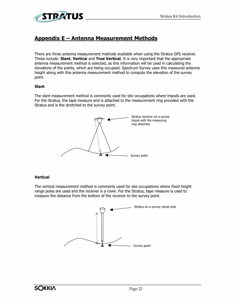
There are three antenna measurement methods available when using the Stratus GPS receiver. These include: Slant, Vertical and True Vertical. It is very important that the appropriate antenna measurement method is selected, as this information will be used in calculating the elevations of the points, which are being occupied. Spectrum Survey uses this measured antenna height along with this antenna measurement method to compute the elevation of the survey point.
Slant The slant measurement method is commonly used for site occupations where tripods are used. For the Stratus, the tape measure end is attached to the measurement ring provided with the Stratus and is the stretched to the survey point.
Survey point
Stratus receiver on a survey tripod with the measuring ring attached.
Vertical The vertical measurement method is commonly used for site occupations where fixed height range poles are used and the receiver is a rover. For the Stratus, tape measure is used to measure the distance from the bottom of the receiver to the survey point.
Survey point
Stratus on a survey range pole
Tplljb! Page 22
Stratus Kit Introduction
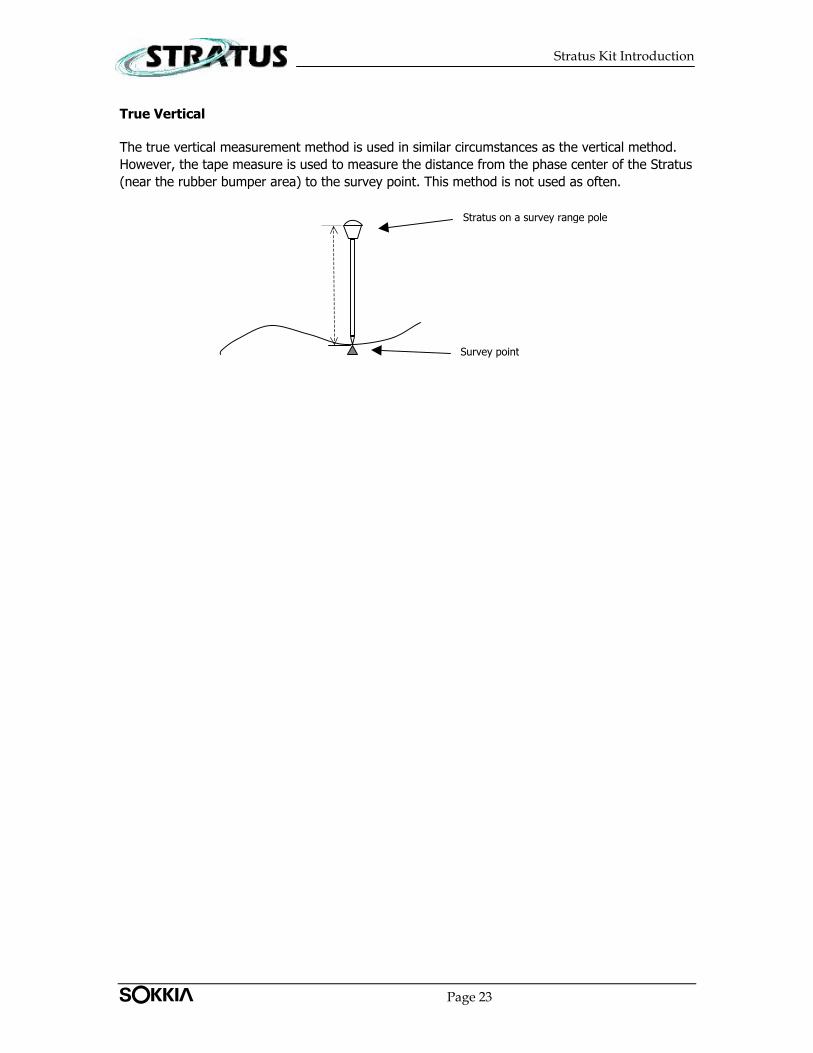
True Vertical
The true vertical measurement method is used in similar circumstances as the vertical method. However, the tape measure is used to measure the distance from the phase center of the Stratus (near the rubber bumper area) to the survey point. This method is not used as often.
Survey point
Stratus on a survey range pole
Tplljb! Page 23