Embed Size (px)
Citation preview
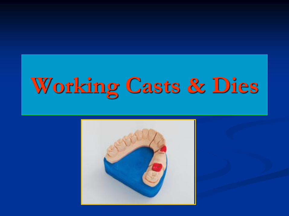
Working Casts & Dies
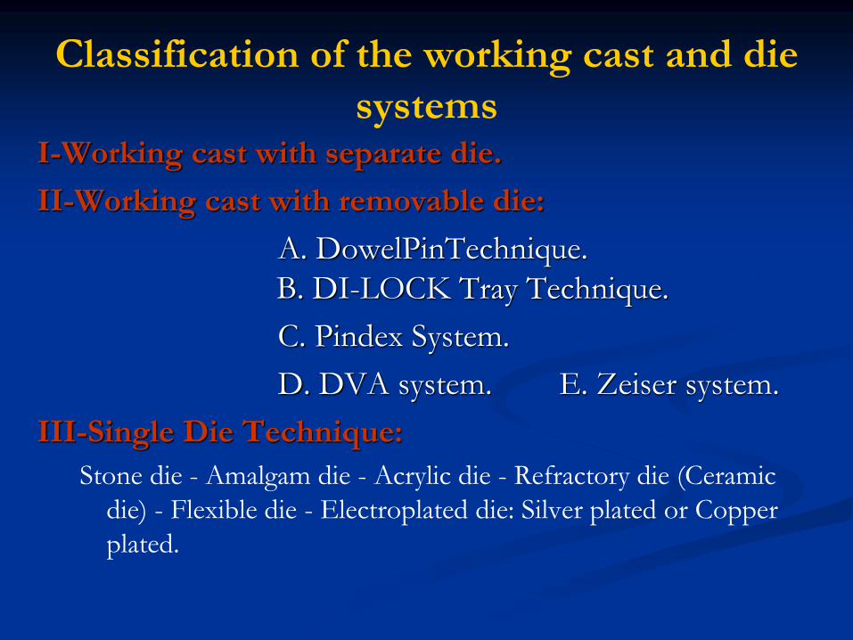
Classification of the working cast and die
systemsI-Working cast with separate die.
II-Working cast with removable die:
A. DowelPinTechnique.
B. DI-LOCK Tray Technique.
C. Pindex System.
D. DVA system. E. Zeiser system.
III-Single Die Technique:
Stone die - Amalgam die - Acrylic die - Refractory die (Ceramic
die) - Flexible die - Electroplated die: Silver plated or Copper
plated.
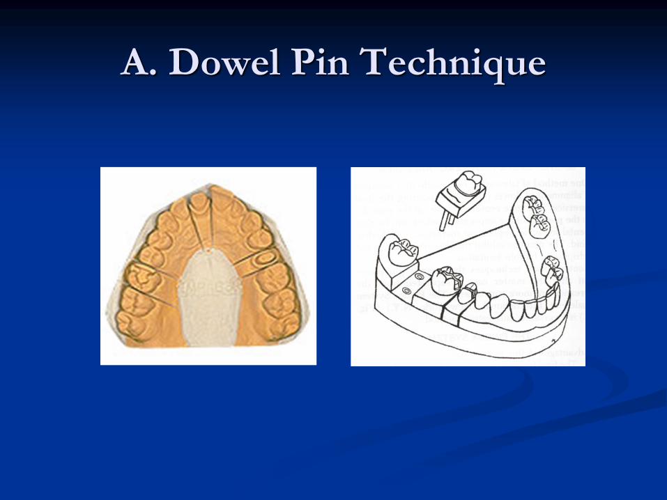
A. Dowel Pin Technique
A. Dowel Pin Technique
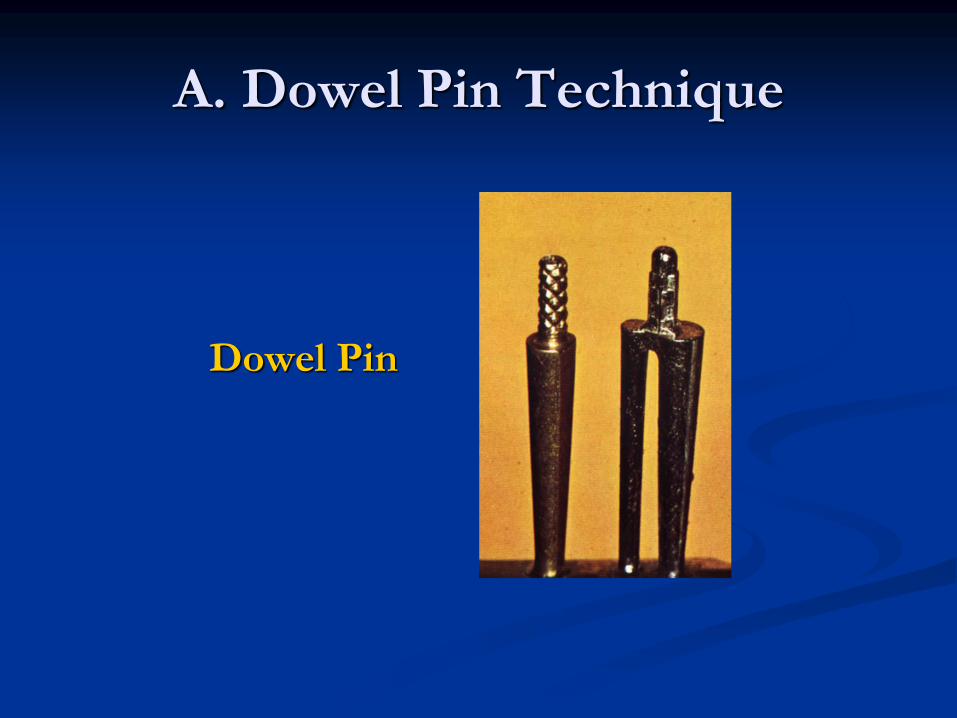
Dowel Pin
A. Dowel Pin Technique
A. Dowel Pin Technique
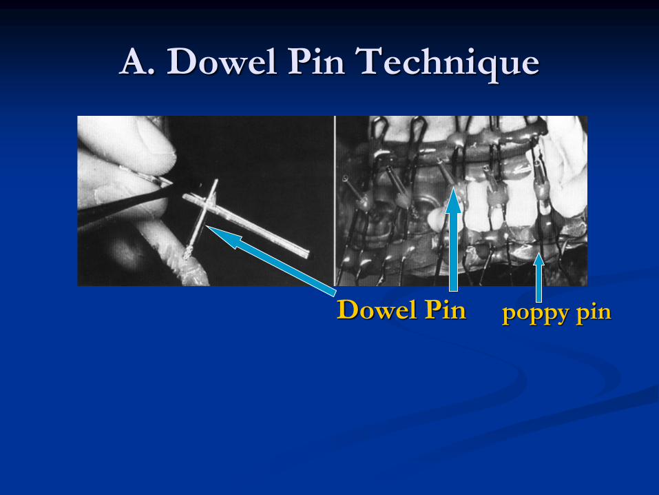
Dowel Pin poppy pin
A. Dowel Pin Technique
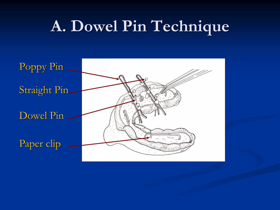
Poppy Pin
Straight Pin
Dowel Pin
Paper clip

A. Dowel Pin Technique
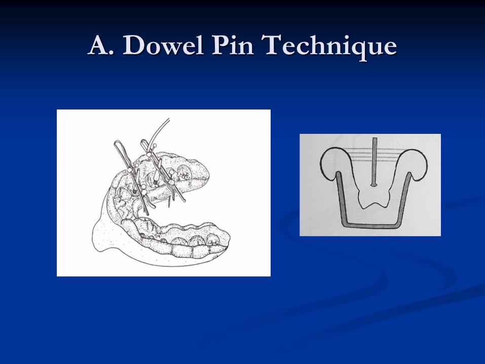
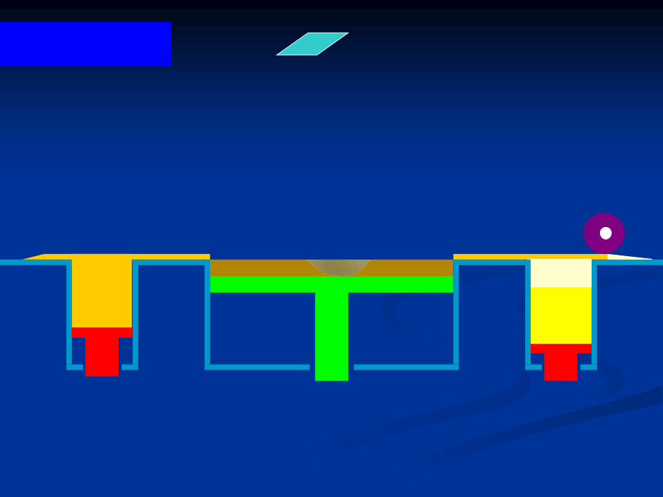
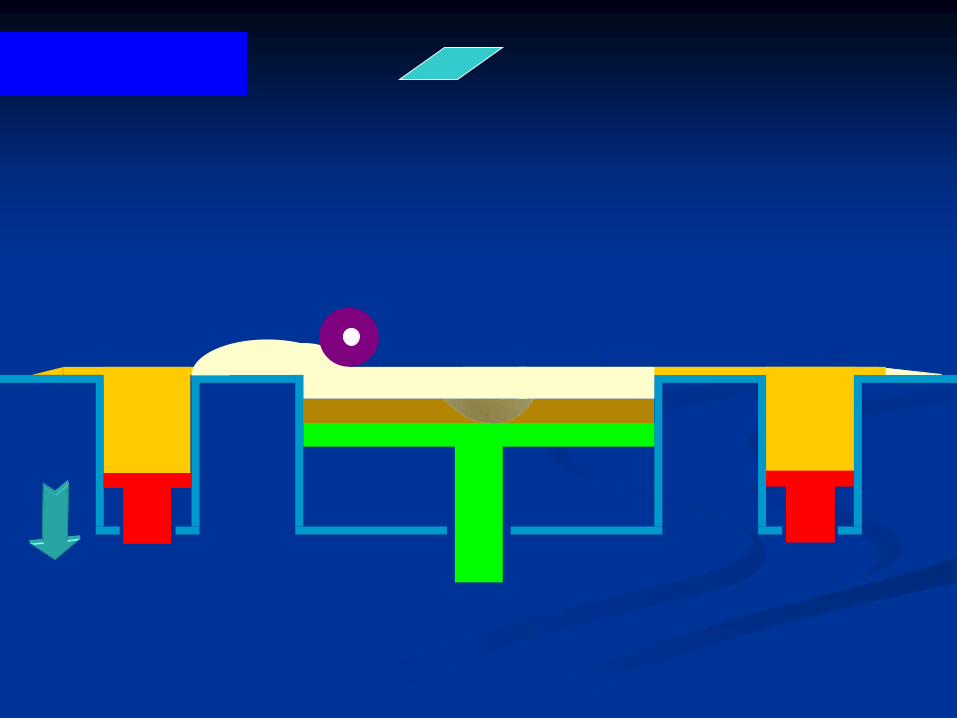
A ball of soft wax is placed on the dowel pin tip and
application of separating medium.
A. Dowel Pin Technique
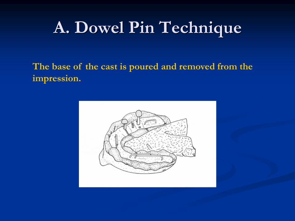
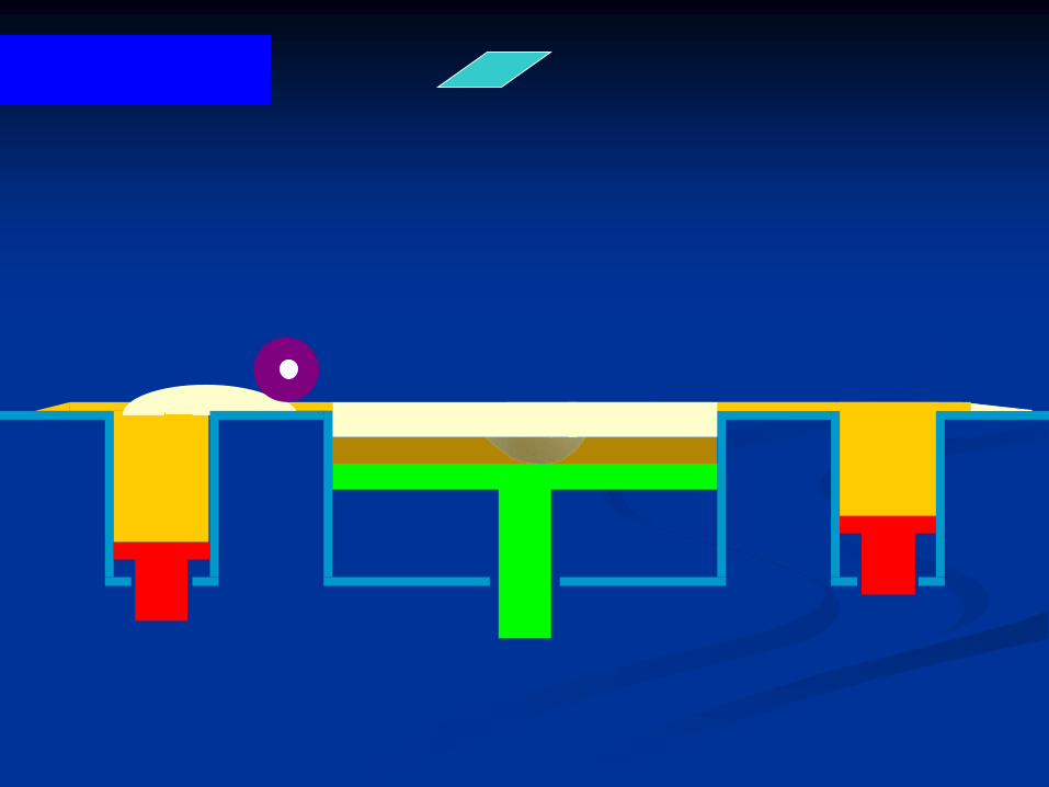
The base of the cast is poured and removed from the
impression.
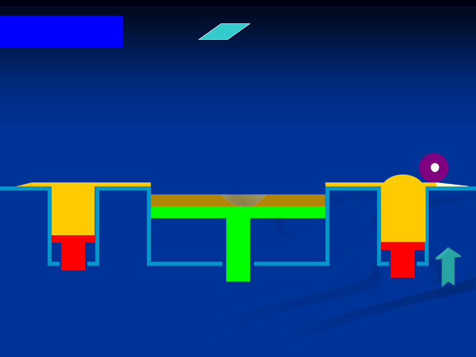
A. Dowel Pin Technique
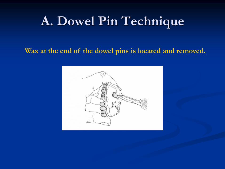
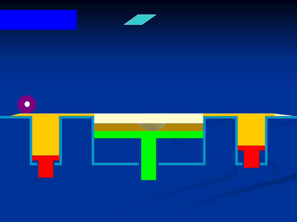
Wax at the end of the dowel pins is located and removed.
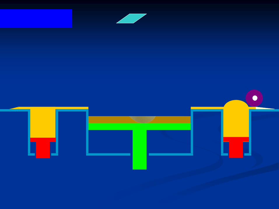
A. Dowel Pin Technique
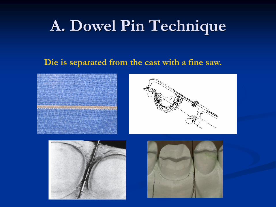
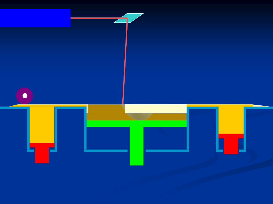
Die is separated from the cast with a fine saw.
A. Dowel Pin Technique
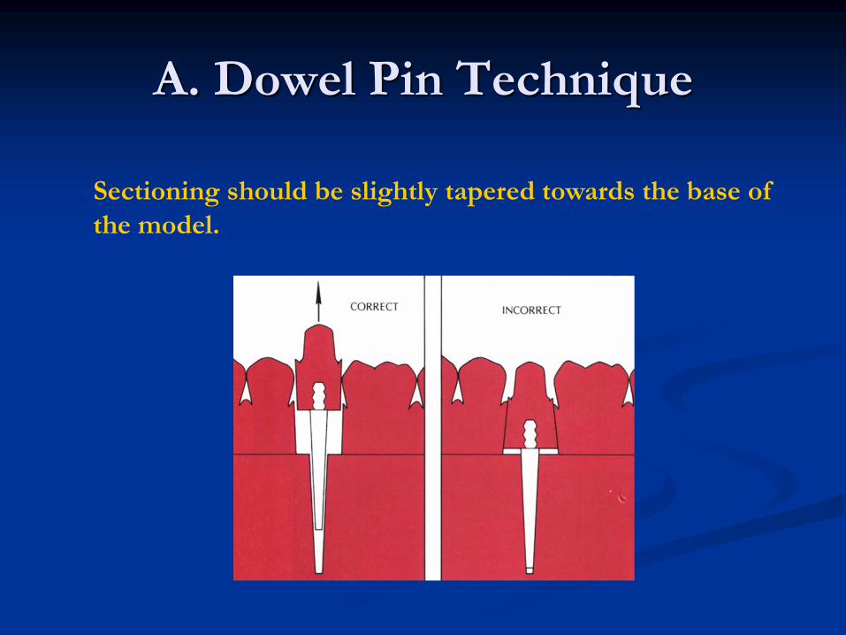
Sectioning should be slightly tapered towards the base of
the model.
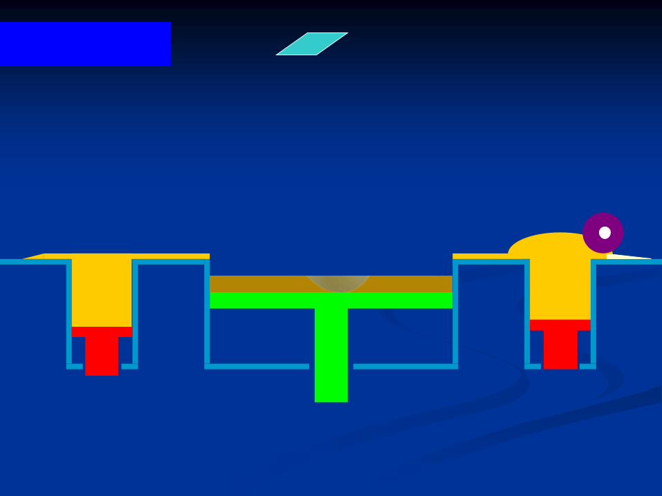
A. Dowel Pin Technique
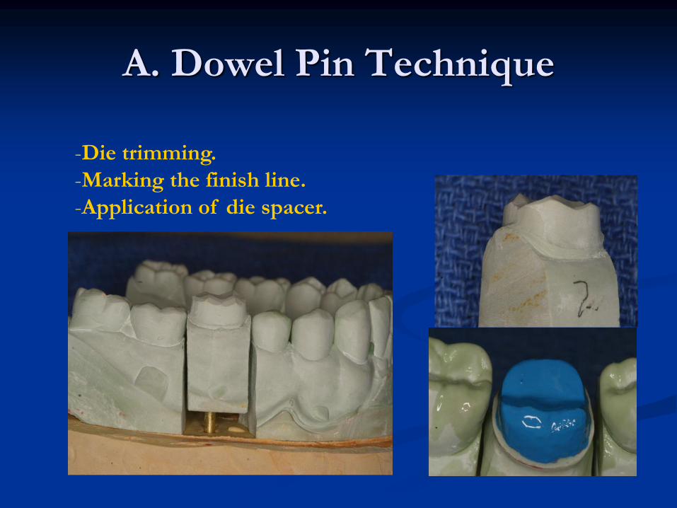
-Die trimming.
-Marking the finish line.
-Application of die spacer.
Classification of the working cast and die
systemsI-Working cast with separate die.
II-Working cast with removable die:
A. Dowel Pin Technique.
B. DI-LOCK Tray Technique.
C. Pindex System.
D. DVA system. E. Zeiser system.
III-Single Die Technique:
Stone die - Amalgam die - Acrylic die - Refractory die (Ceramic
die) - Flexible die - Electroplated die: Silver plated or Copper
plated.
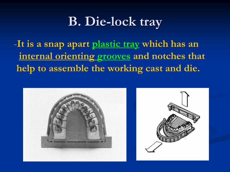
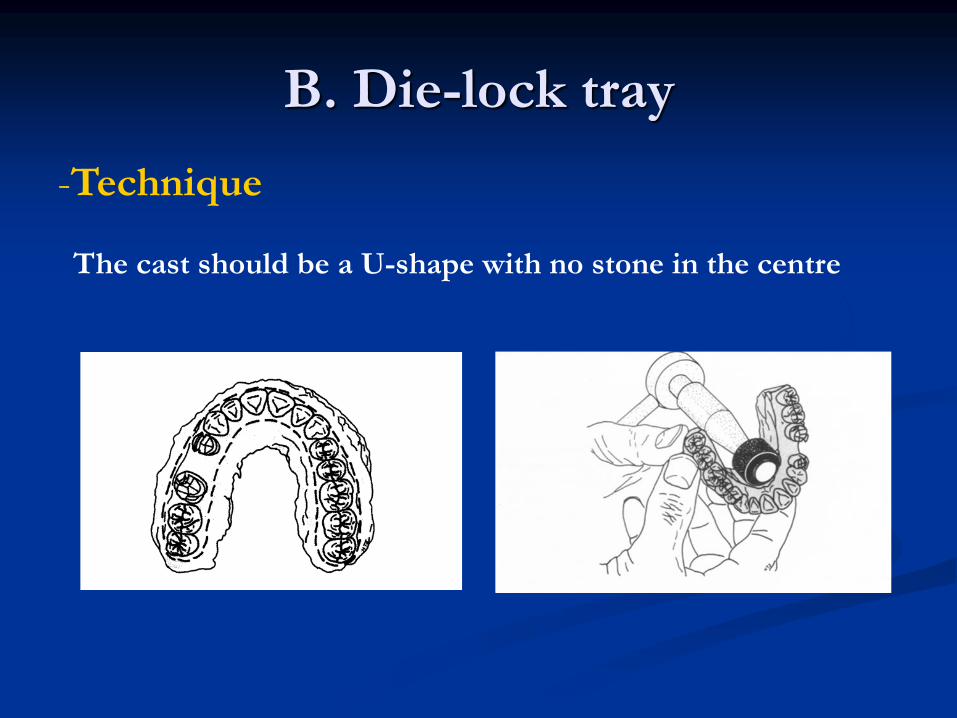
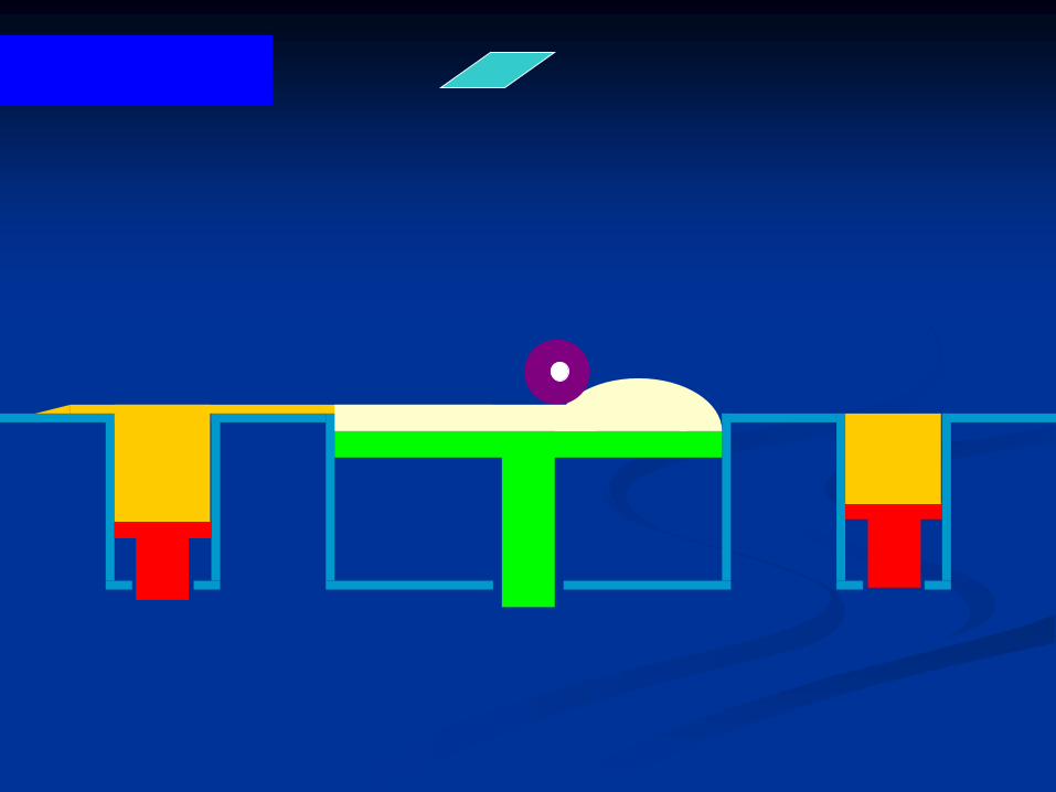
B. Die-lock tray
-It is a snap apart plastic tray which has an
internal orienting grooves and notches that
help to assemble the working cast and die.
B. Die-lock tray
-Technique
The cast should be a U-shape with no stone in the centre
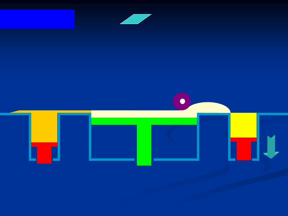
B. Die-lock tray
-Technique
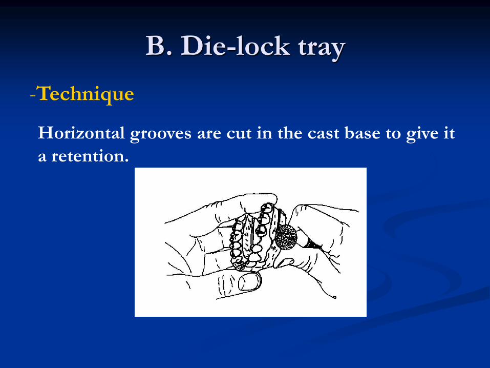
Horizontal grooves are cut in the cast base to give it
a retention.

B. Die-lock tray
-Technique
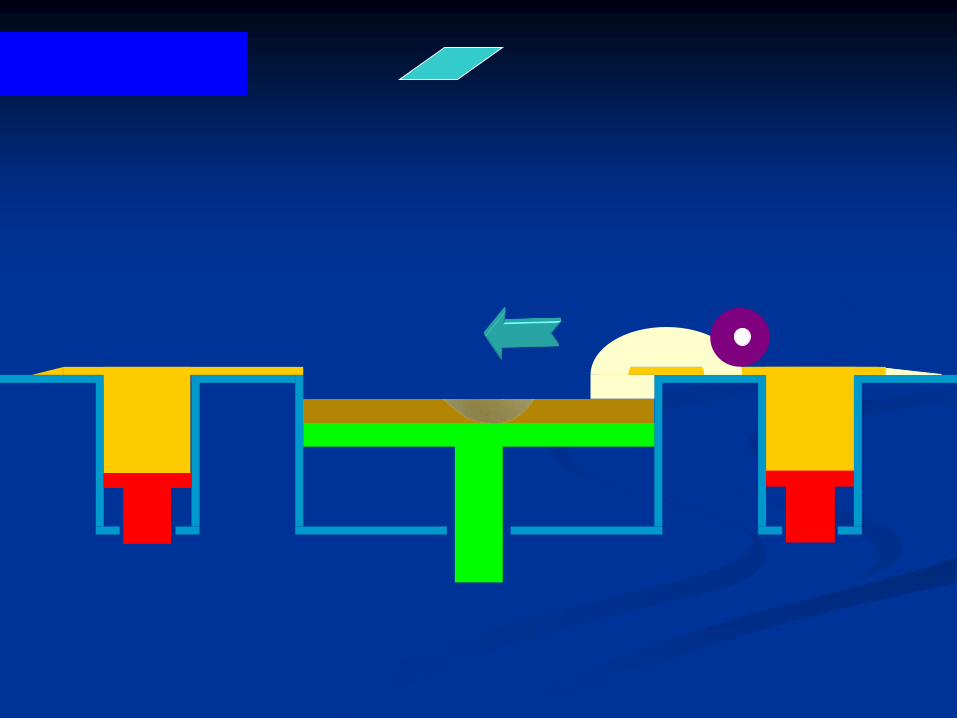
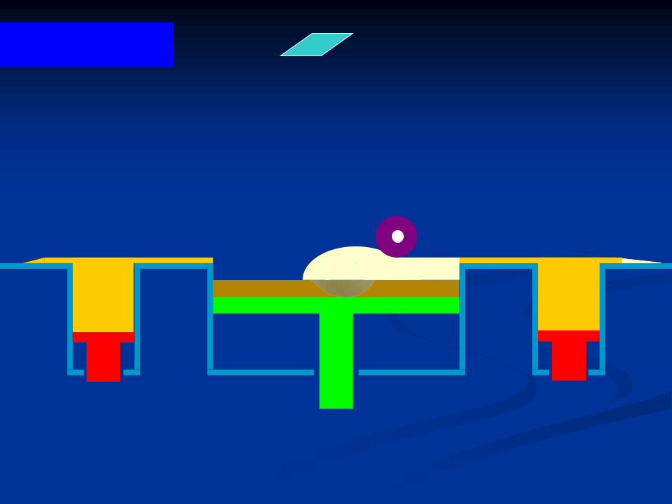
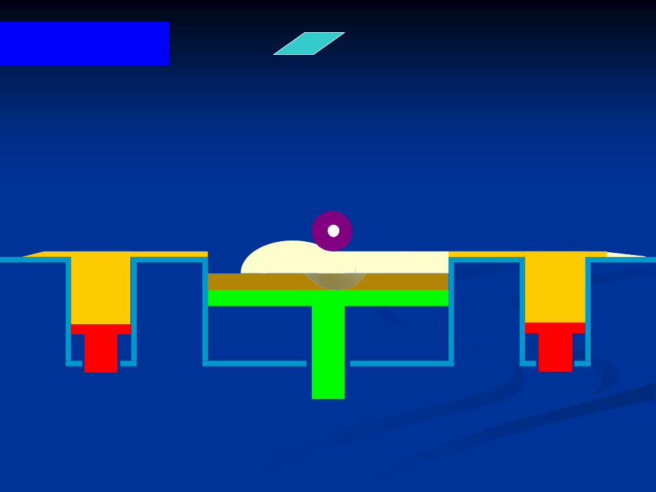
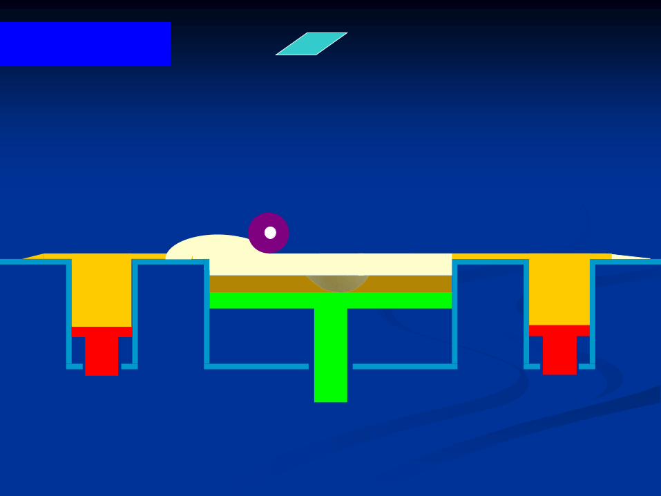
● The tray is filled with a new mix of dental stone.
● The U-shaped cast is seated in the tray on the stone mix.
● The cervical line of the teeth should be 4 mm above the tray
edge.
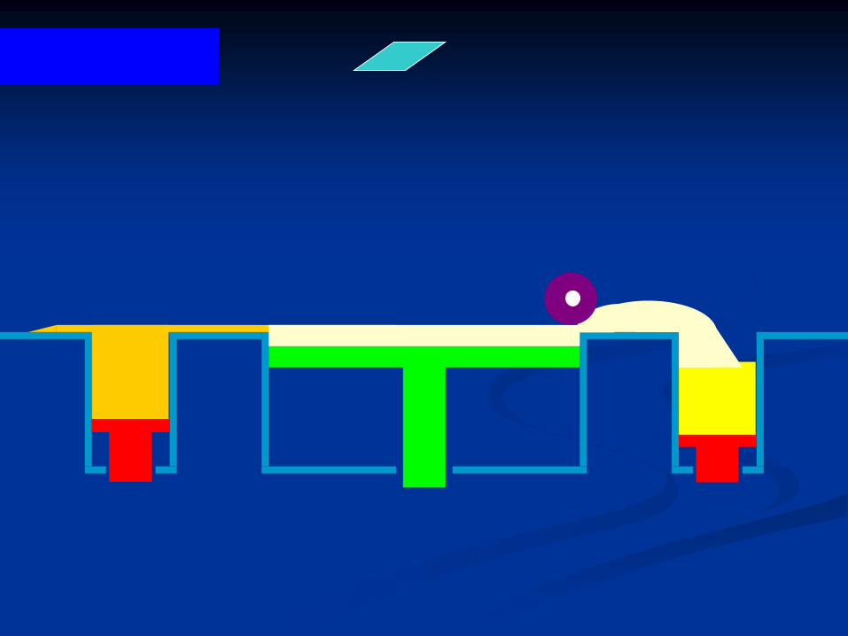
B. Die-lock tray
-Technique
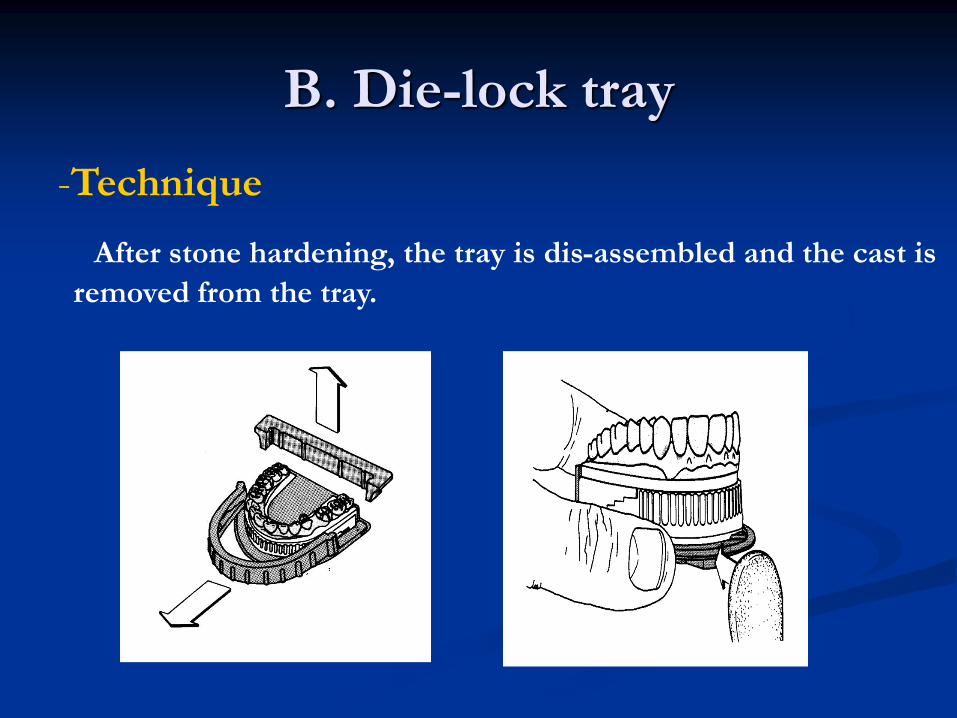
After stone hardening, the tray is dis-assembled and the cast is
removed from the tray.
B. Die-lock tray
-Technique
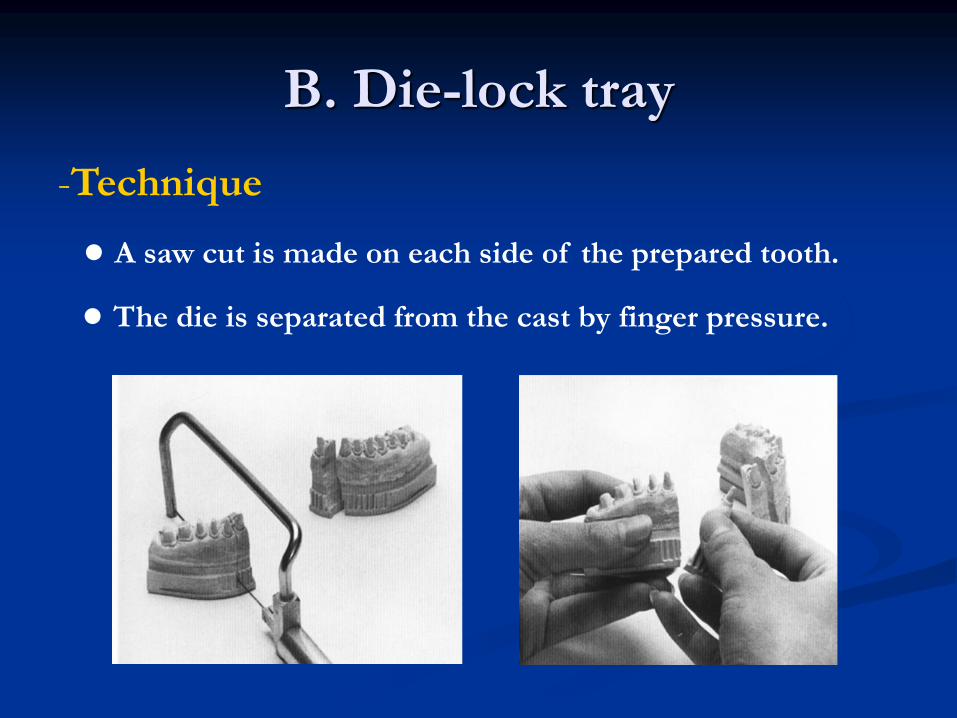
● A saw cut is made on each side of the prepared tooth.
● The die is separated from the cast by finger pressure.
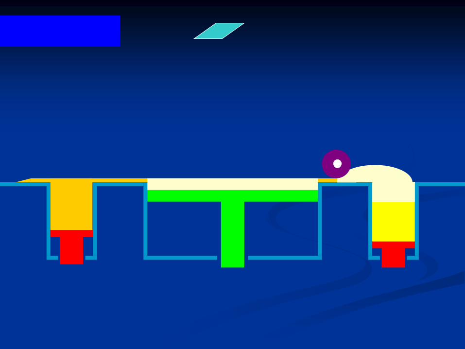
B. Die-lock tray
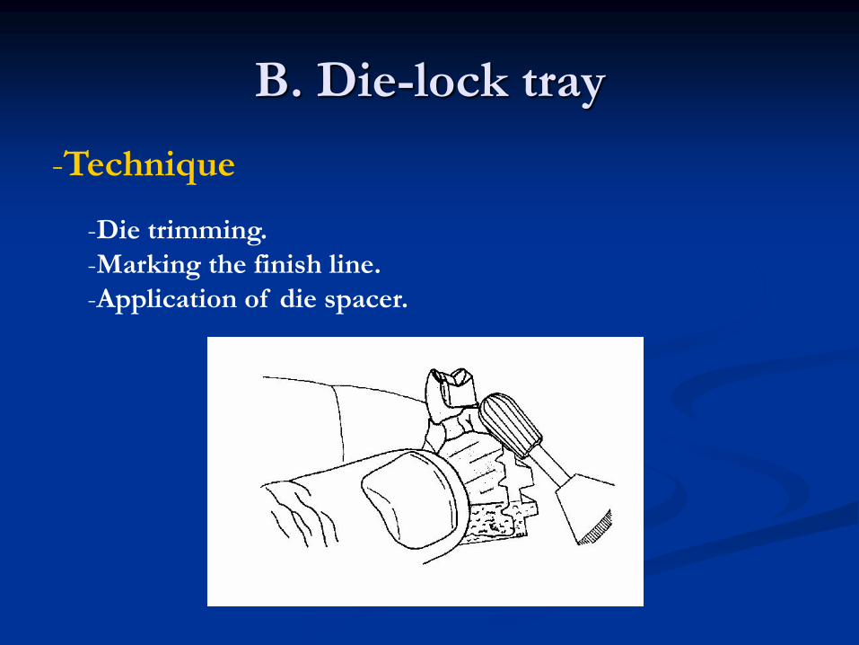
-Technique
-Die trimming.
-Marking the finish line.
-Application of die spacer.
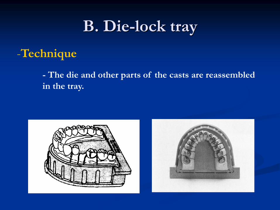
B. Die-lock tray
-Technique
- The die and other parts of the casts are reassembled
in the tray.
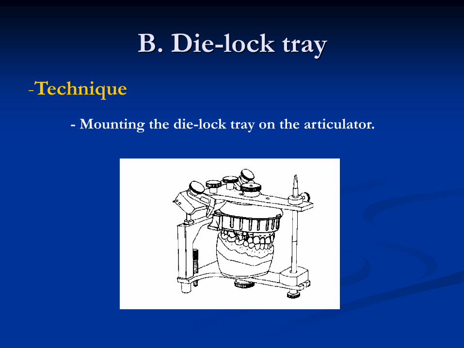
B. Die-lock tray
-Technique
- Mounting the die-lock tray on the articulator.
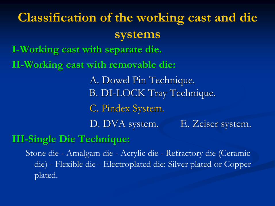
Classification of the working cast and die
systemsI-Working cast with separate die.
II-Working cast with removable die:
A. Dowel Pin Technique.
B. DI-LOCK Tray Technique.
C. Pindex System.
D. DVA system. E. Zeiser system.
III-Single Die Technique:
Stone die - Amalgam die - Acrylic die - Refractory die (Ceramic
die) - Flexible die - Electroplated die: Silver plated or Copper
plated.
using
working cast with removable die
Pindex system
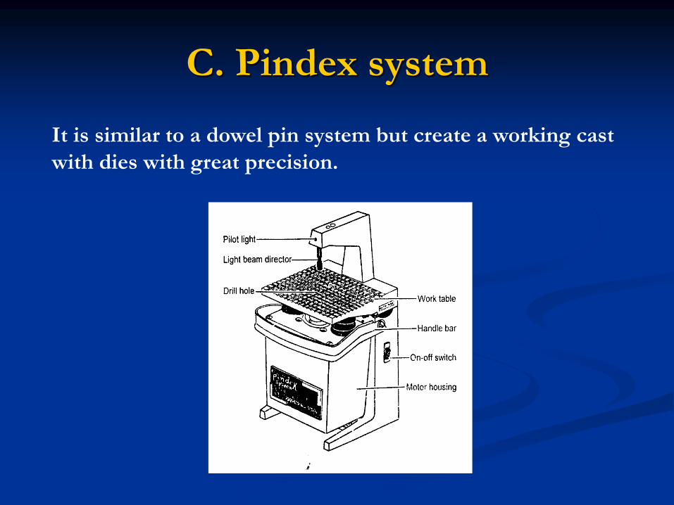
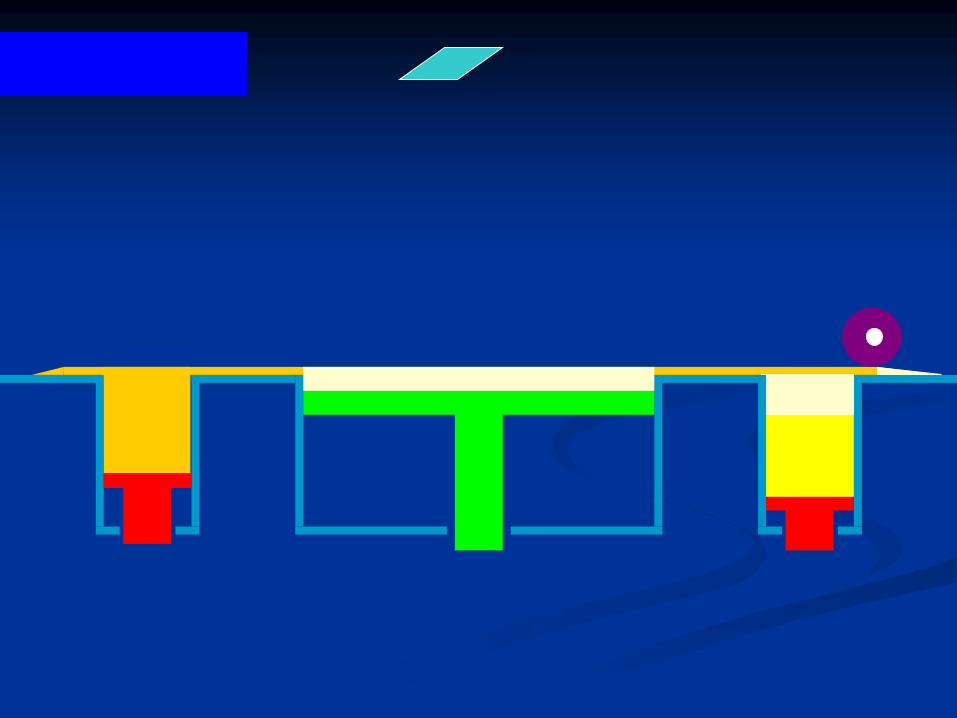
C. Pindex system
It is similar to a dowel pin system but create a working cast
with dies with great precision.
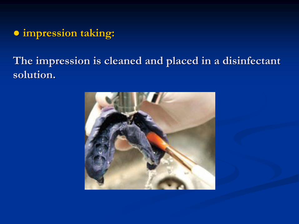
● impression taking:
The impression is cleaned and placed in a disinfectant
solution.
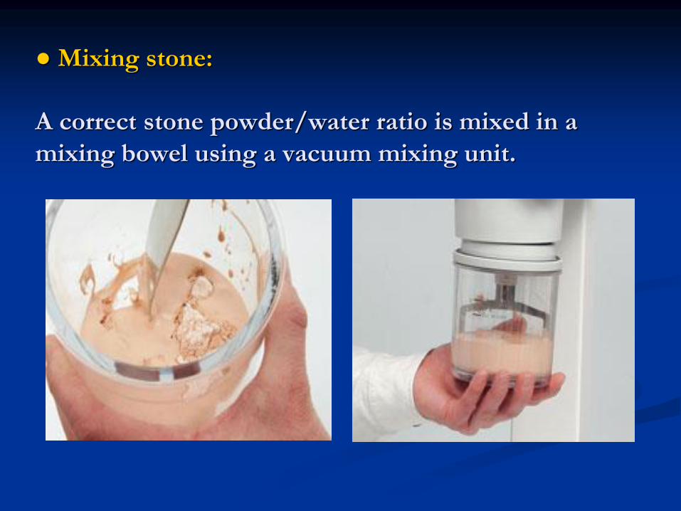
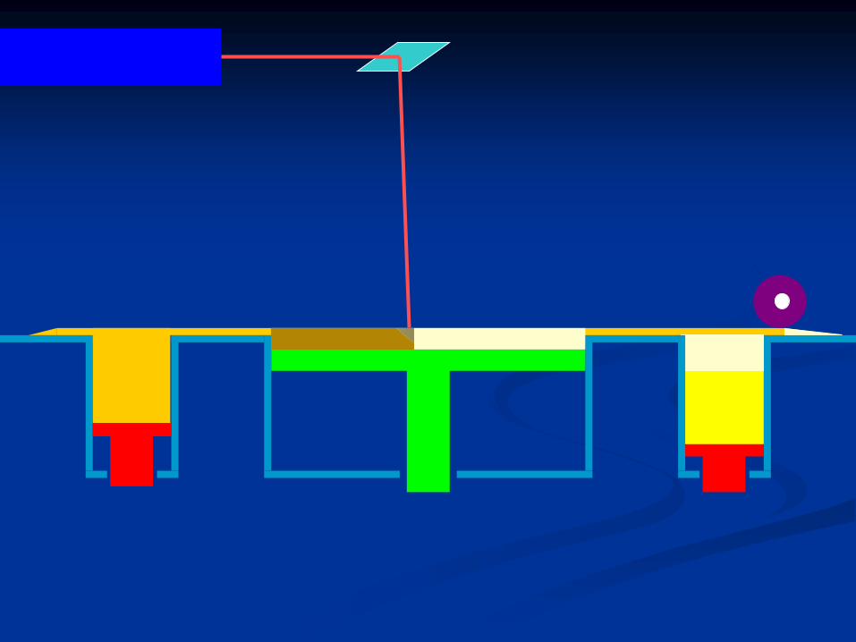
● Mixing stone:
A correct stone powder/water ratio is mixed in a
mixing bowel using a vacuum mixing unit.
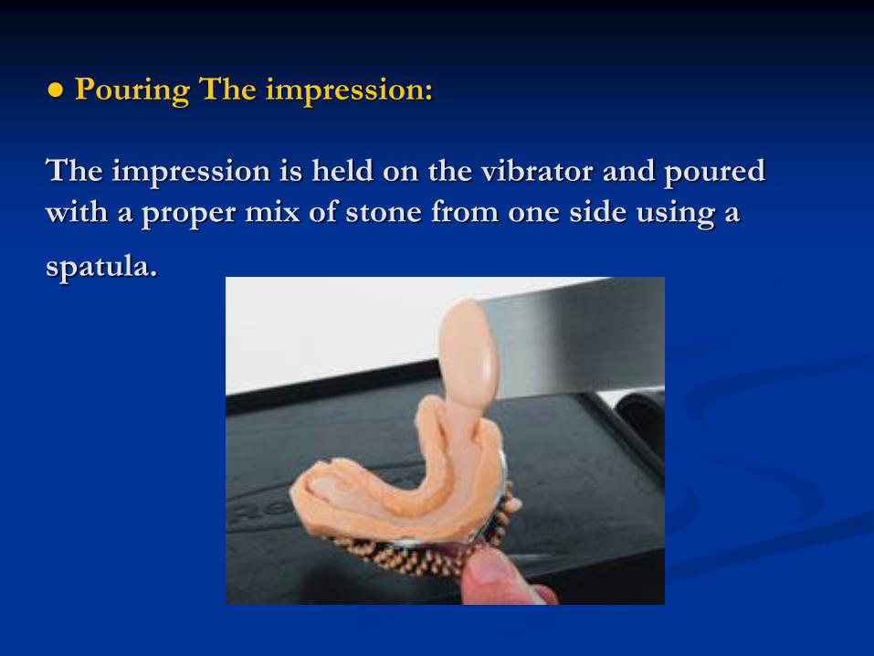
● Pouring The impression:
The impression is held on the vibrator and poured
with a proper mix of stone from one side using a
spatula.
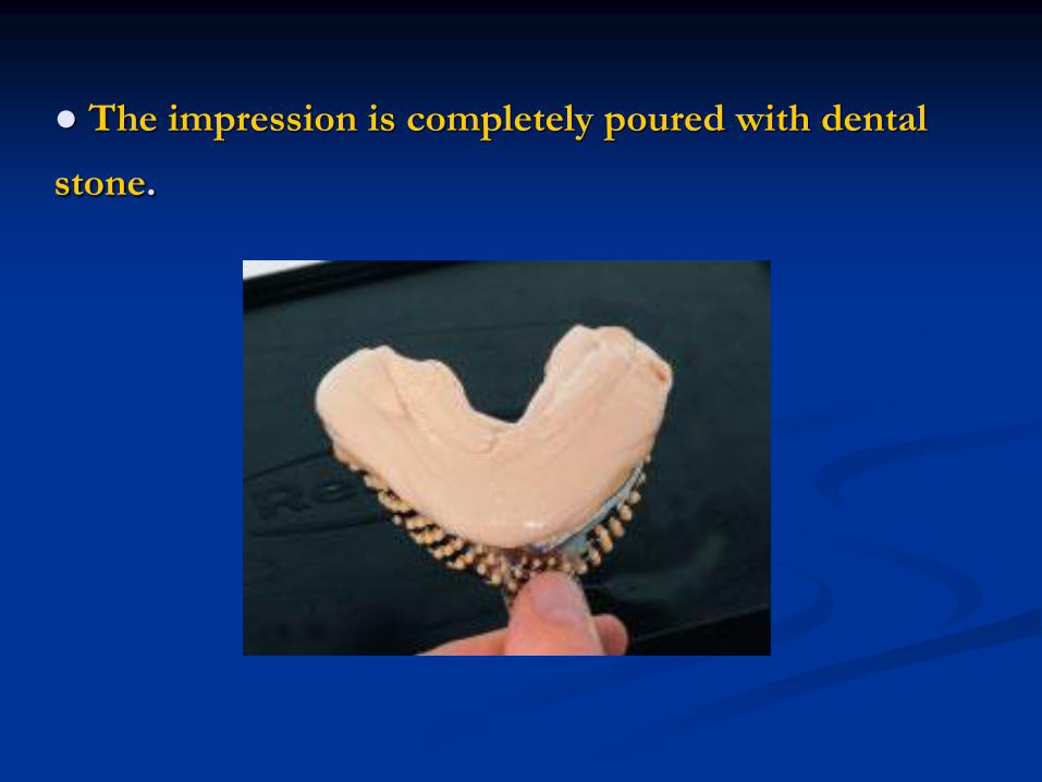
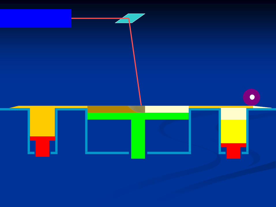
● The impression is completely poured with dental
stone.
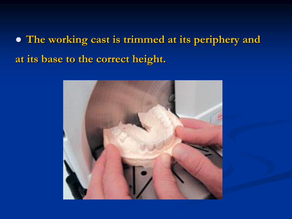
● The working cast is trimmed at its periphery and
at its base to the correct height.
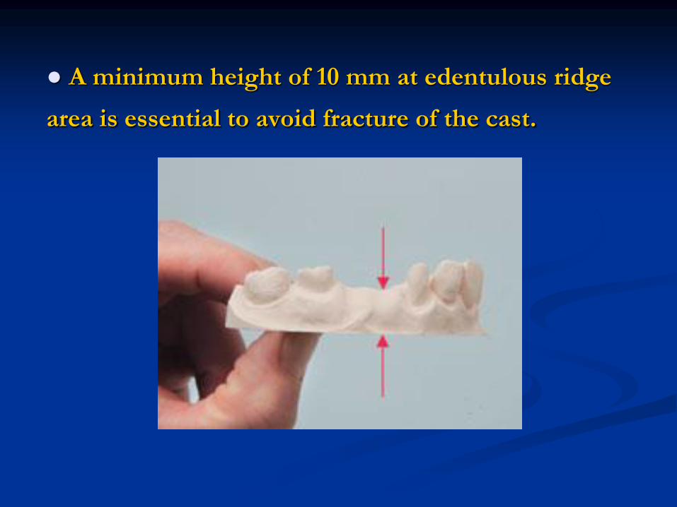
● A minimum height of 10 mm at edentulous ridge
area is essential to avoid fracture of the cast.
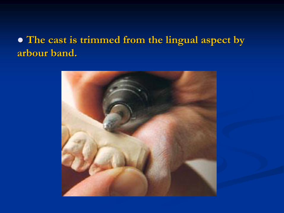
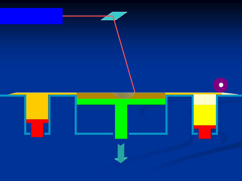
● The cast is trimmed from the lingual aspect by
arbour band.
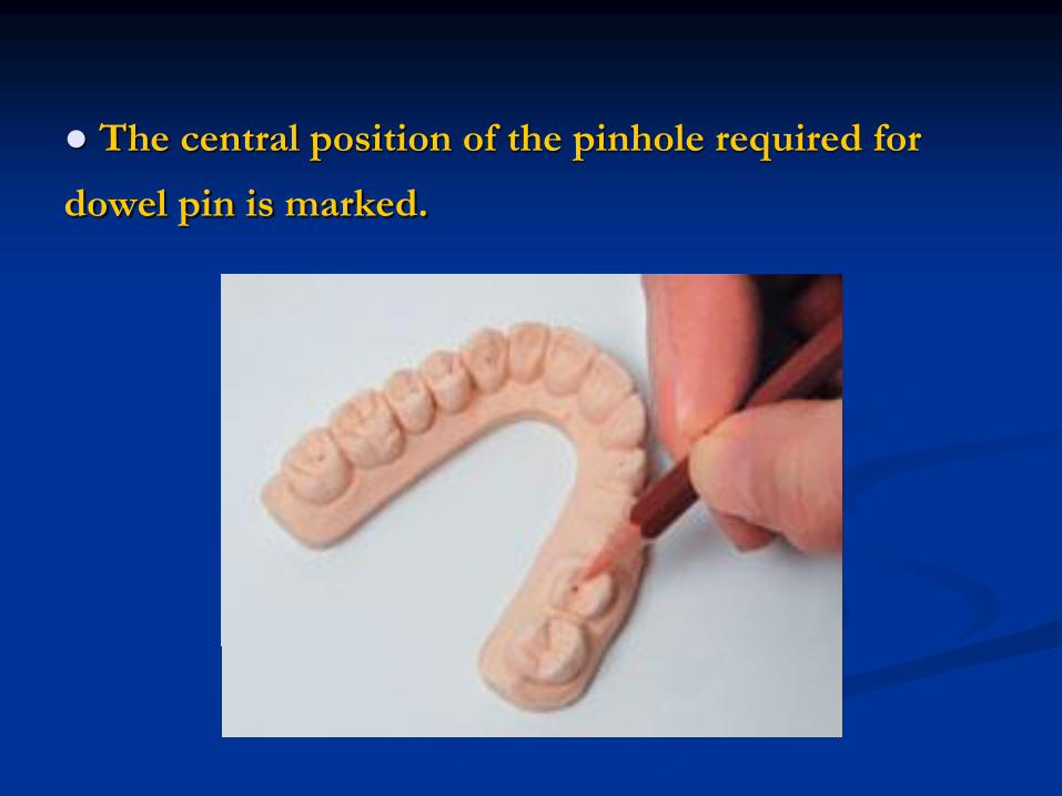
● The central position of the pinhole required for
dowel pin is marked.

● All crowns, bridge units and adjacent teeth should
be pinned.
● The rest of the dental arch should also be
supported by at least two dowel pins.
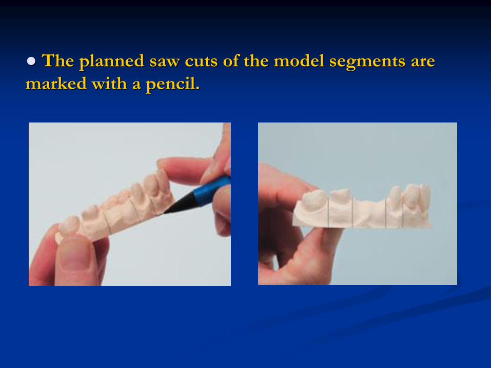
● The planned saw cuts of the model segments are
marked with a pencil.
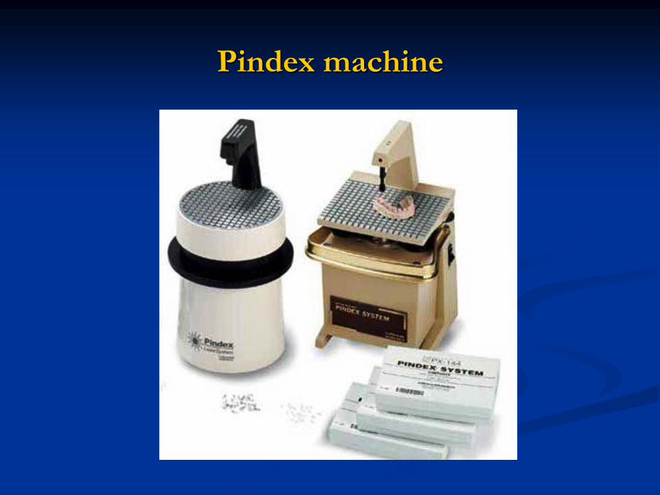
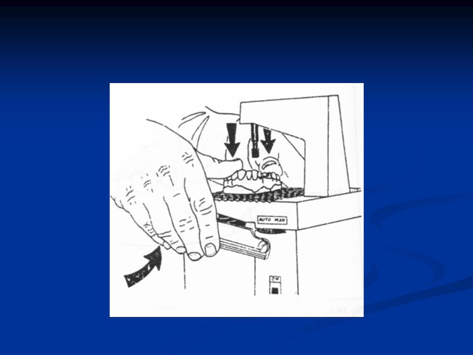
Pindex machine
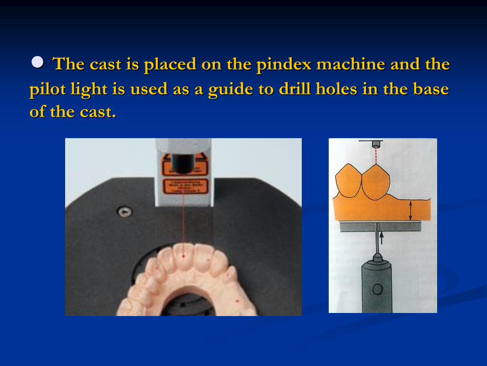
● The cast is placed on the pindex machine and the
pilot light is used as a guide to drill holes in the base
of the cast.

● The platform of the pindex machine is spring
loaded. When the cast is pressed against the
platform, the motor will get activated to drill a hole in
the base of the cast.
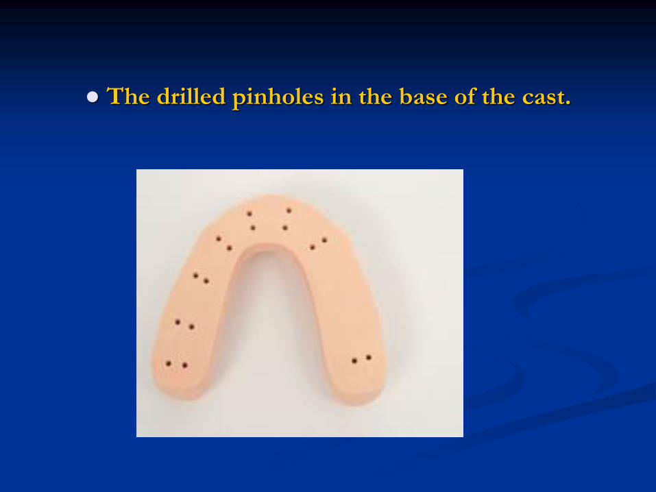
● The drilled pinholes in the base of the cast.
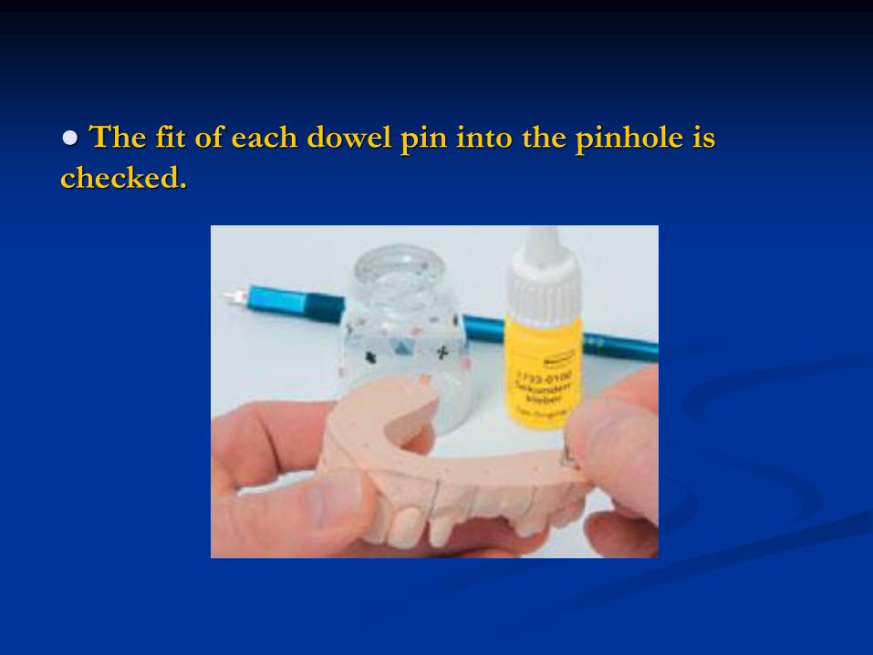
● The fit of each dowel pin into the pinhole is
checked.
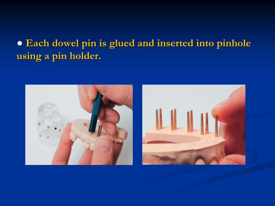
● Each dowel pin is glued and inserted into pinhole
using a pin holder.
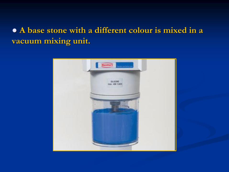
● A base stone with a different colour is mixed in a
vacuum mixing unit.

● After applying a separating medium at the base of
the cast, the pins are coated with the stone on the
vibrator.
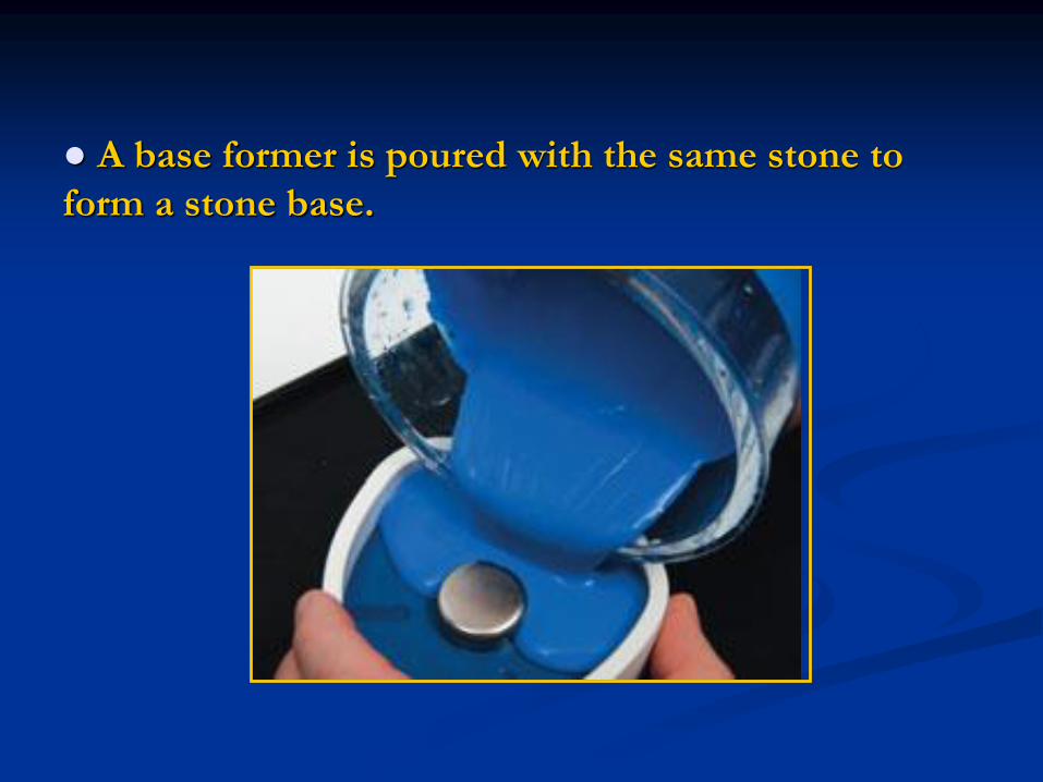
● A base former is poured with the same stone to
form a stone base.
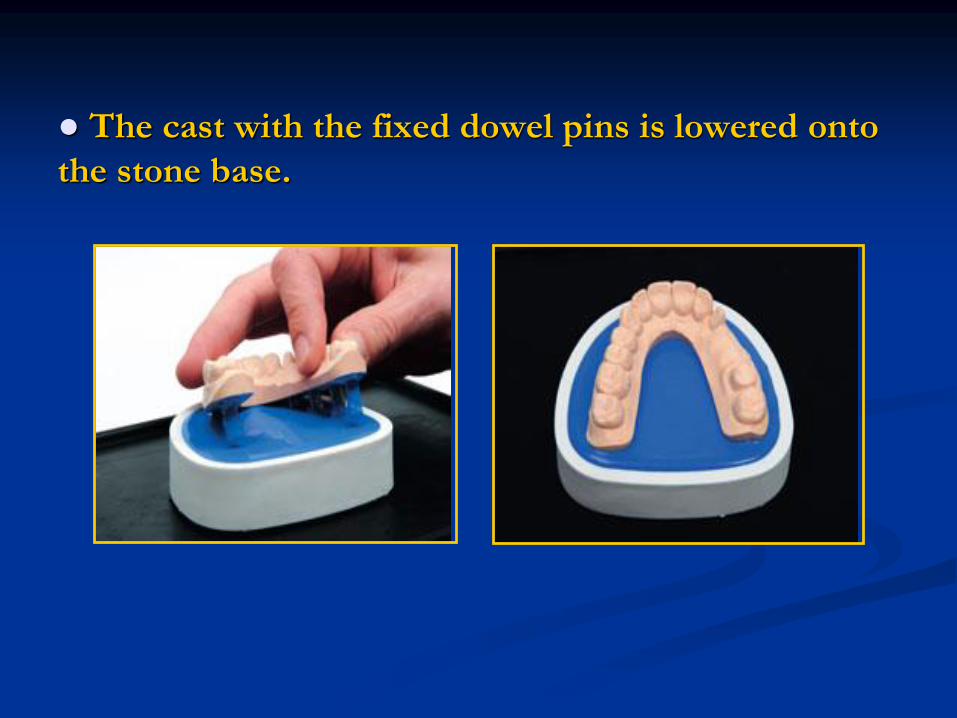
● The cast with the fixed dowel pins is lowered onto
the stone base.
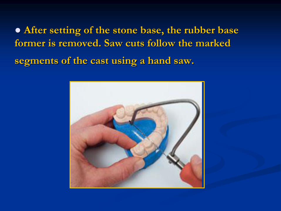
● After setting of the stone base, the rubber base
former is removed. Saw cuts follow the marked
segments of the cast using a hand saw.
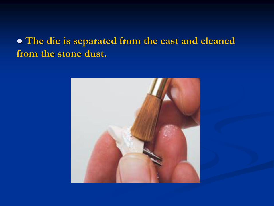
● The die is separated from the cast and cleaned
from the stone dust.
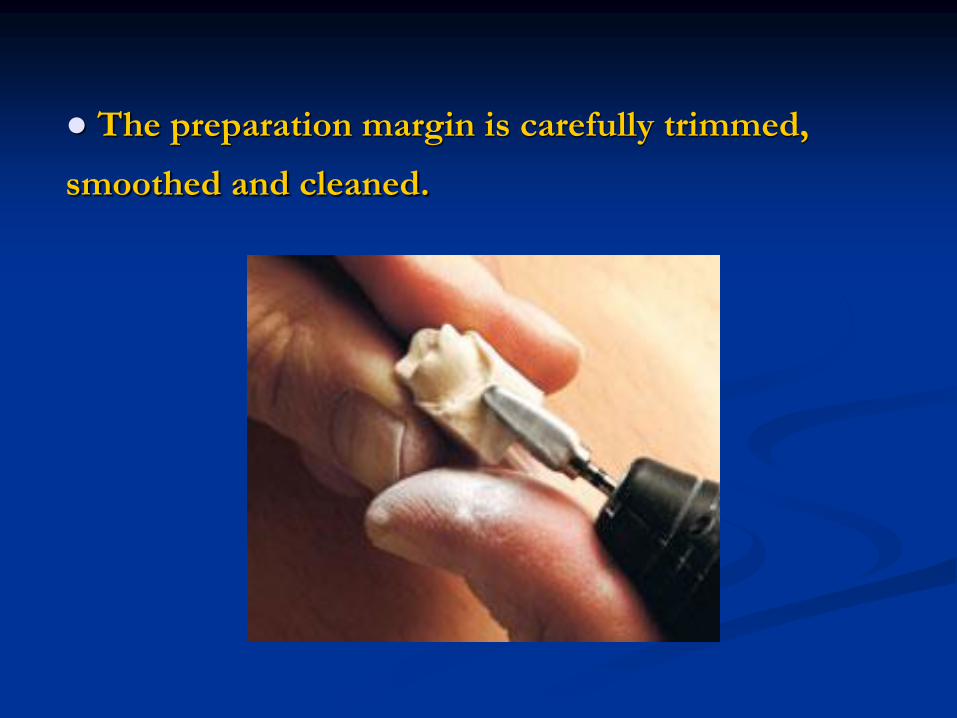
● The preparation margin is carefully trimmed,
smoothed and cleaned.
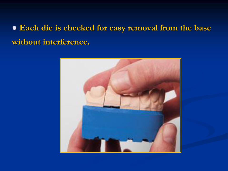
● Each die is checked for easy removal from the base
without interference.
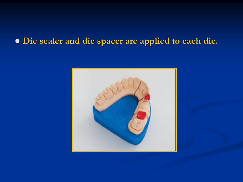
● Die sealer and die spacer are applied to each die.
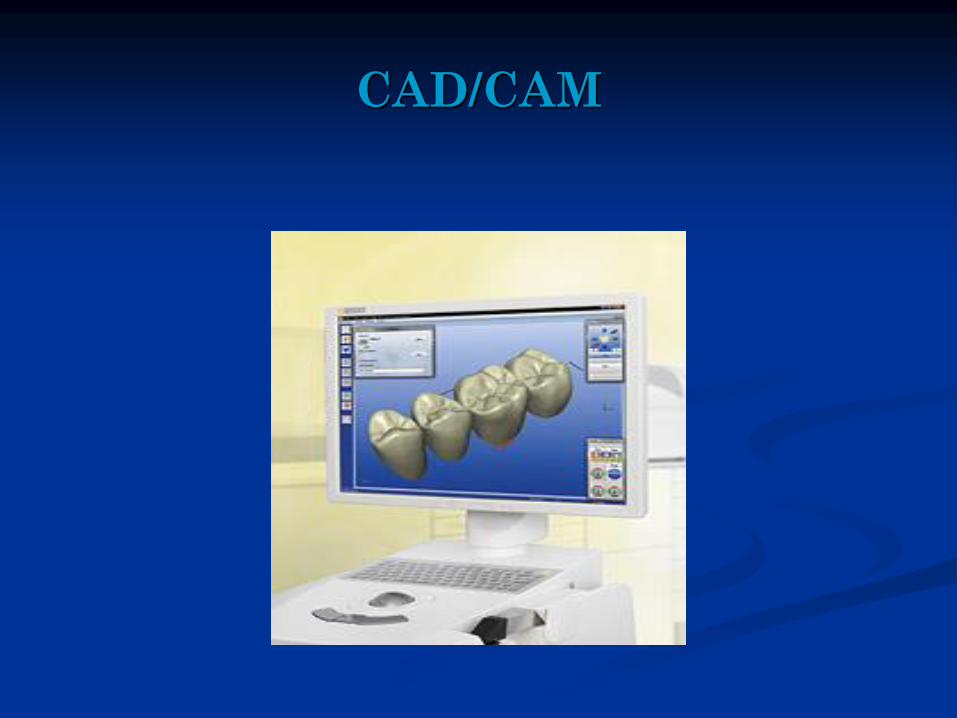
CAD/CAM
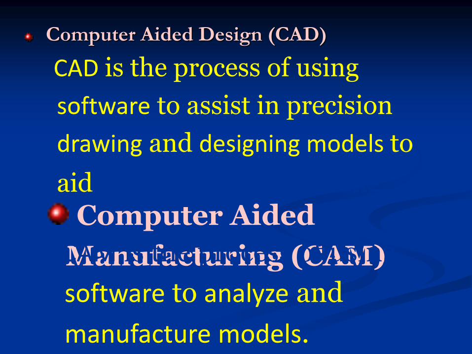
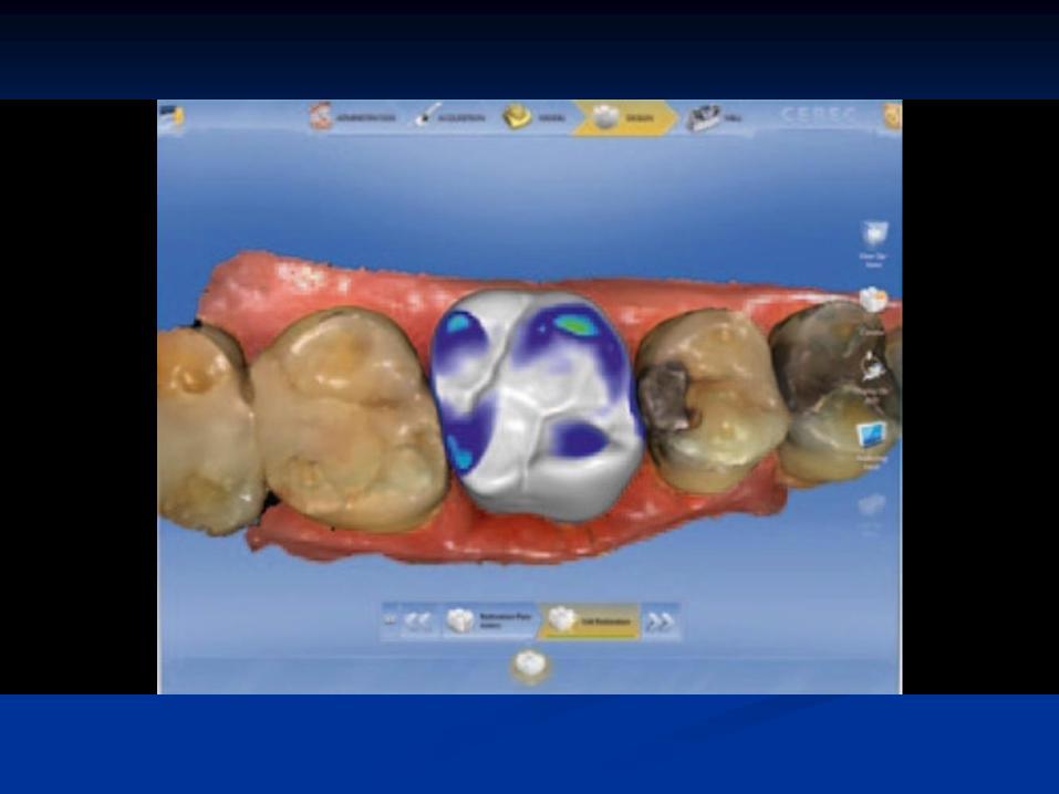
Computer Aided Design (CAD)
CAD is the process of using
software to assist in precision
drawing and designing models to
aid in their manufacturing.Computer Aided
Manufacturing (CAM)CAM is the process of using
software to analyze and
manufacture models.
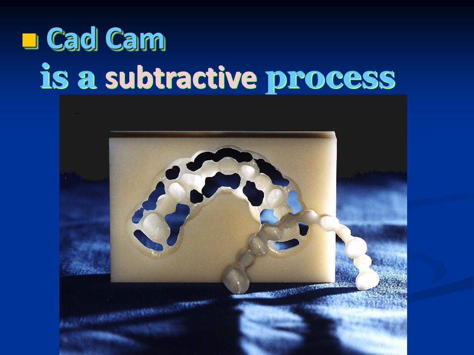
◼ Cad Camis a subtractive process
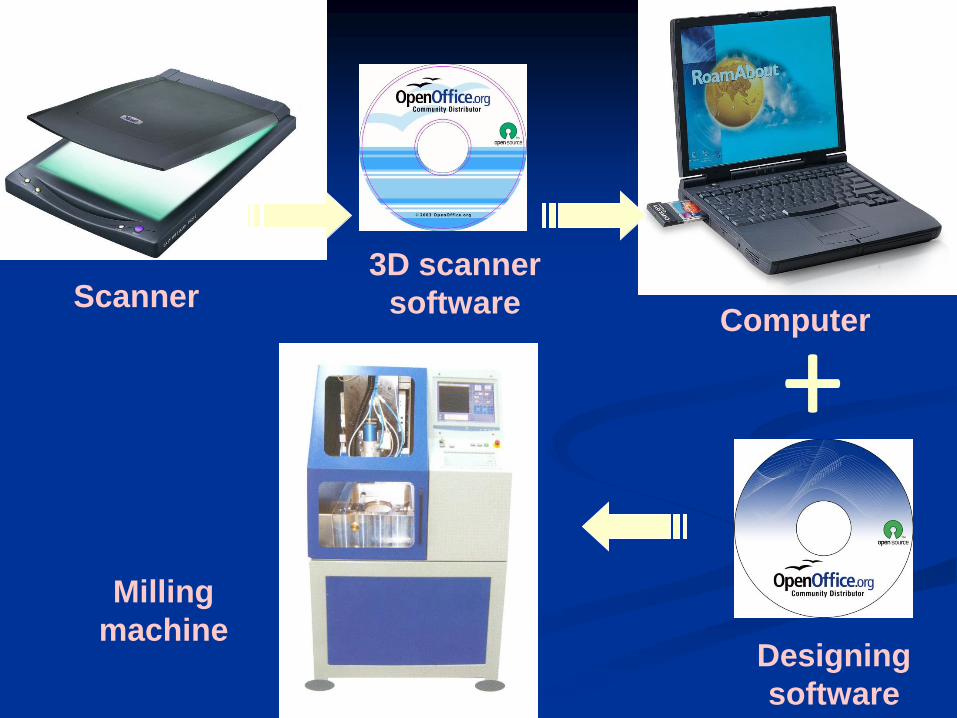
+Scanner
3D scanner
softwareComputer
Designing
software
Milling
machine
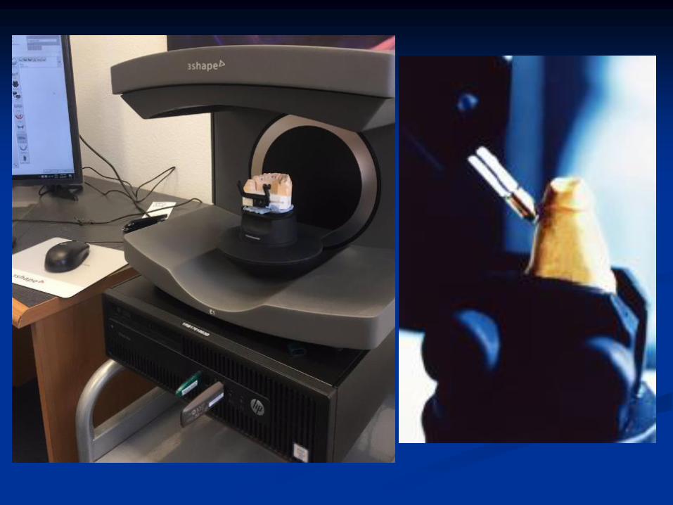
◼ Digitizing (scanners)
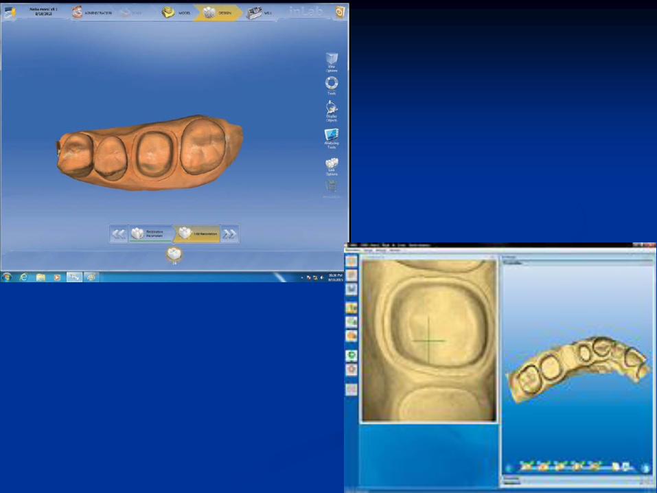
◼ Designing (software)
◼ Milling
CAD CAM


Digitizing
Designing
Milling
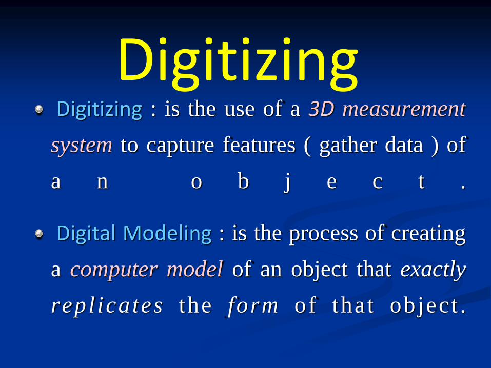
Digitizing : is the use of a 3D measurement
system to capture features ( gather data ) of
a n o b j e c t .
Digital Modeling : is the process of creating
a computer model of an object that exactly
repl icates the form of that object .
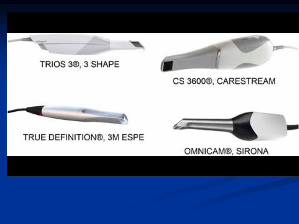
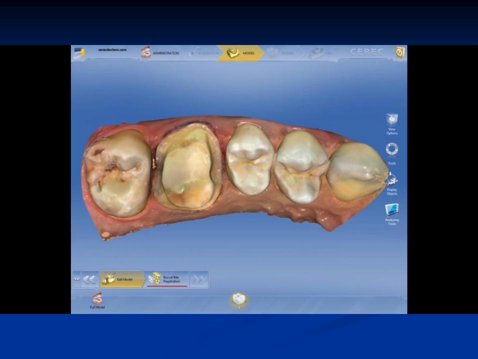
Digitizing
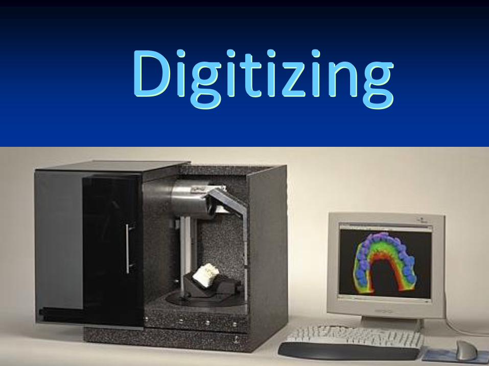
Digitizing
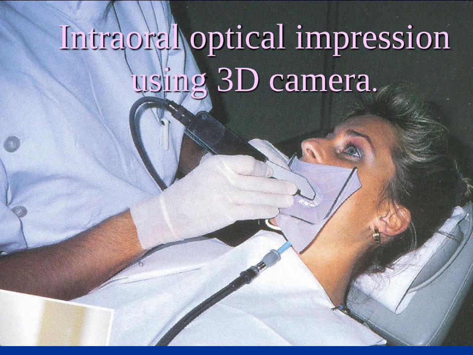
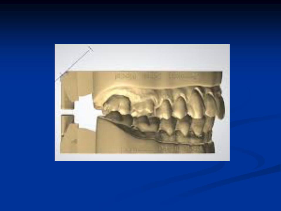
Intraoral optical impression
using 3D camera.
Fast
Rapid
production of a prototype (trial product ,model or sample (
typingproto type
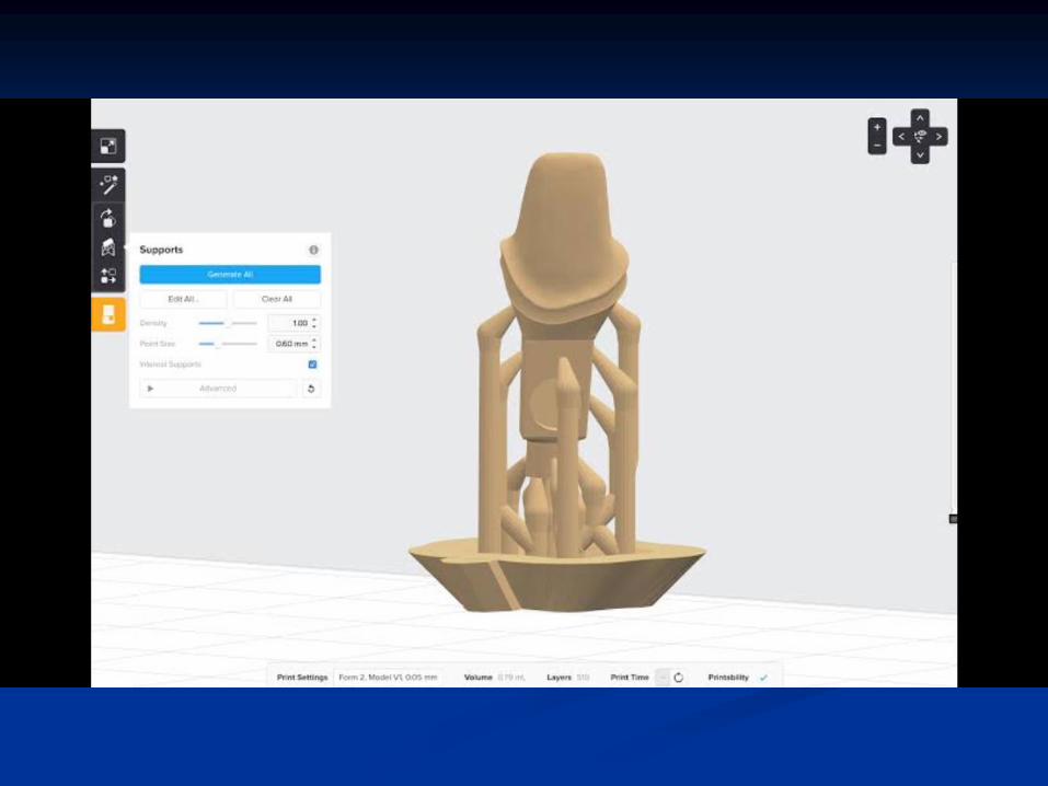
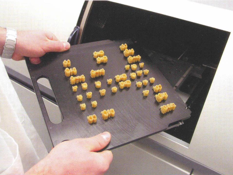
What is RP ?
An additive manufacturing
process that creates an object
directly from a CAD model by
building it in layers
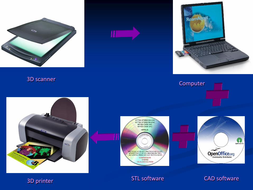
3D scanner Computer
CAD softwareSTL software3D printer
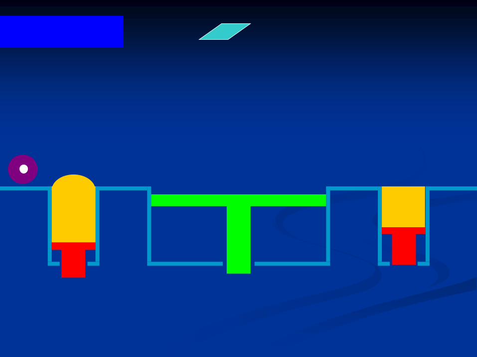
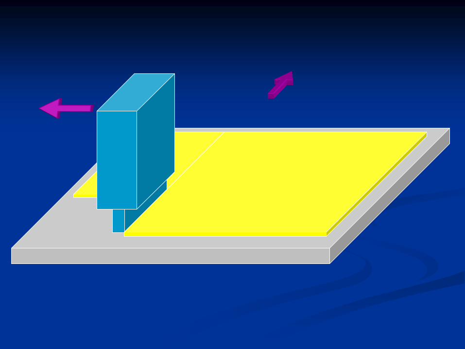
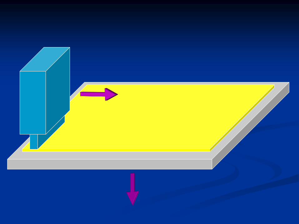
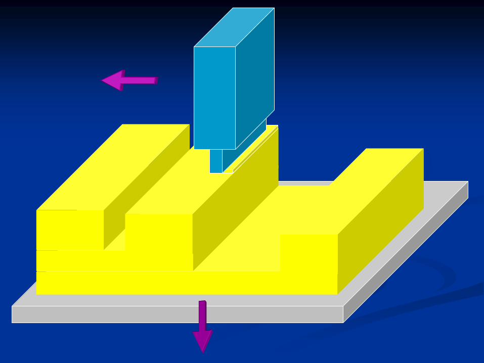
Selective Laser Sintering (SLS)
◼ It uses laser to draw cross-sections in a bed of fine,
heat-fusible powder. The laser raises the temperature of
the powder particles momentarily to where they sinter
(“Sintering,” means welding without melting.).
◼ SLS works with a broad range of materials powder,
including thermoplastics, metal powder, casting wax
and ceramic powder.
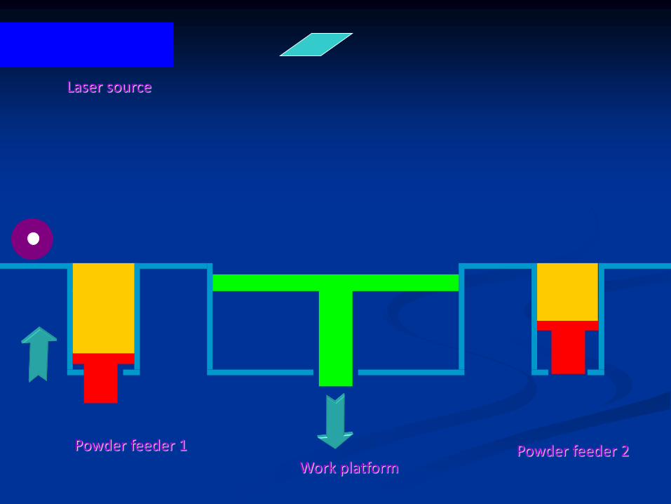
Laser source
Powder feeder 1 Powder feeder 2Work platform


SLS-2500

Fused Deposition Modeling (FDM)
◼ FDM acts like a finely controlled hot-melt glue
gun. But instead of glue, FDM gingerly extrudes
an ultra thin layer of thermoplastic filament.
◼ Actually, two filaments are extruded: one for the
model and the other for the undercut/overhang
support.
◼ No laser is involved.
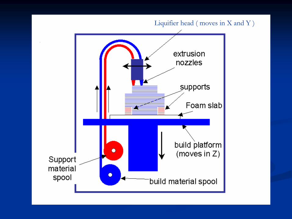
Liquifier head ( moves in X and Y )
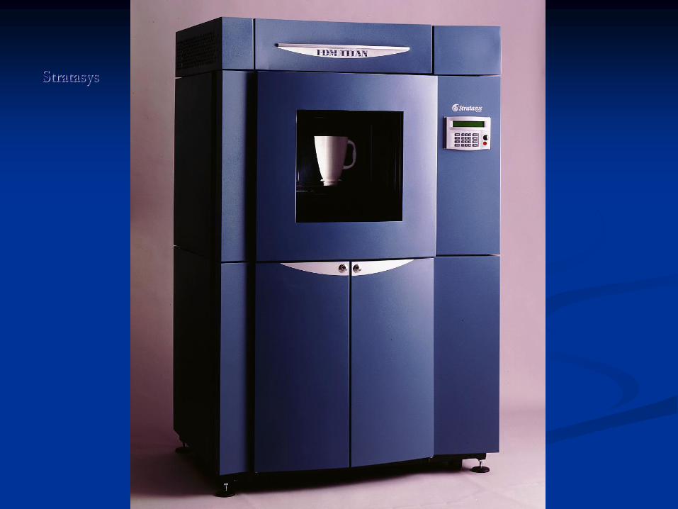
Stratasys

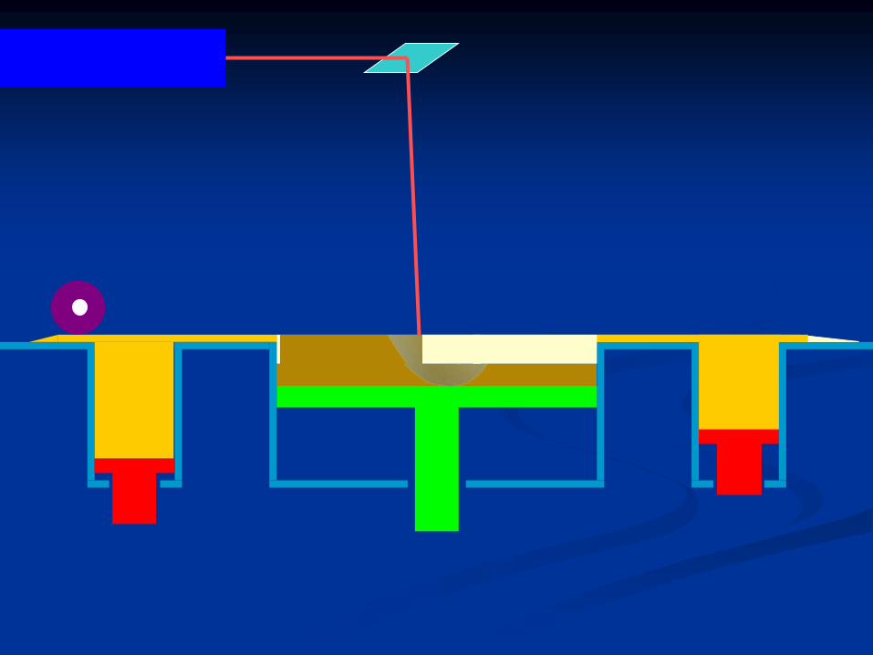
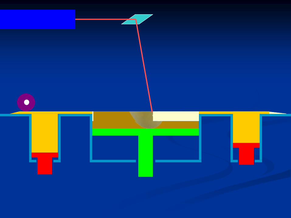
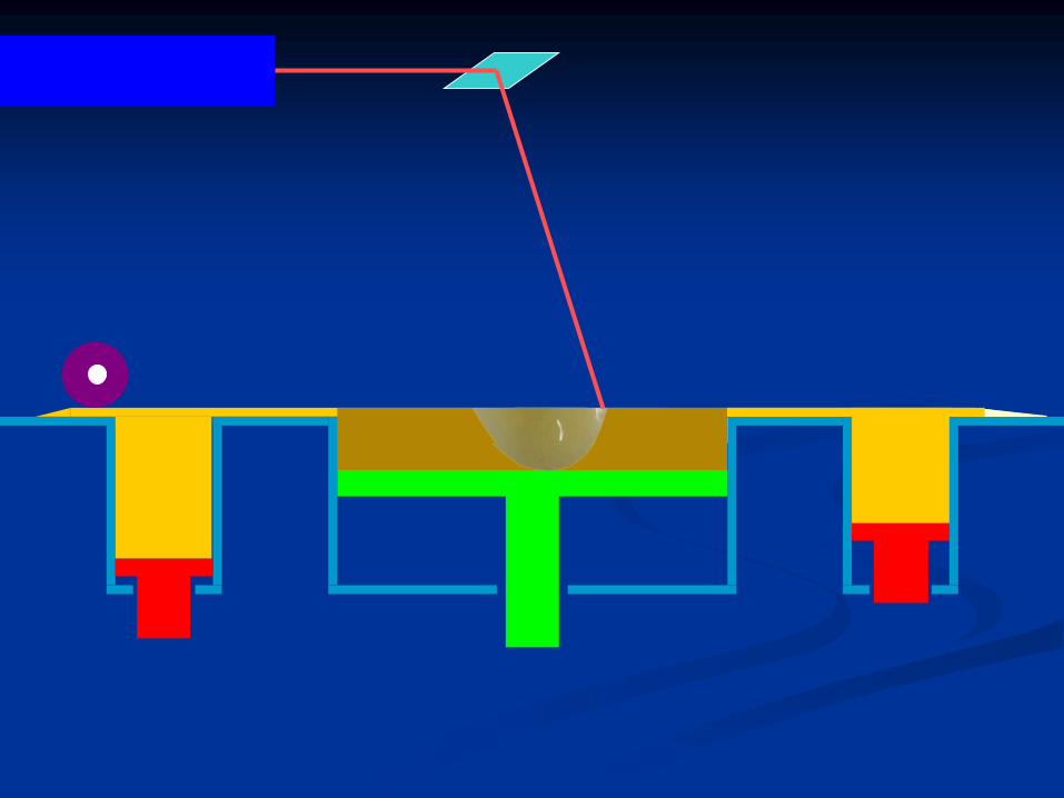
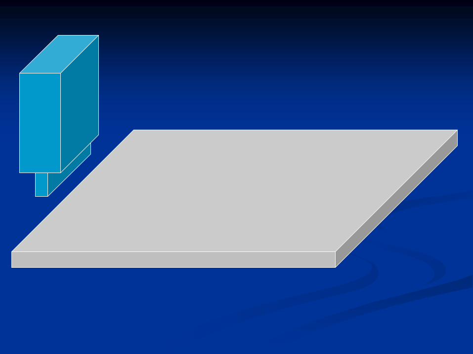
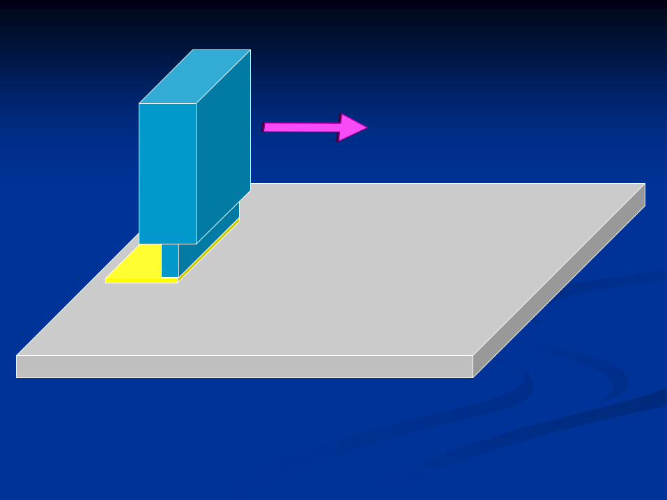
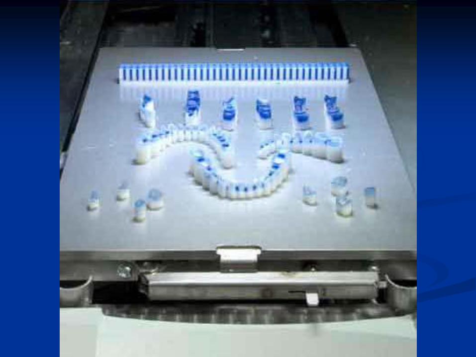
Three-Dimensional Printing (3DP)
◼ Imagine an ink-jet printer. Now think of it producing
3D prototypes instead of printed pages. That’s the 3DP
technology.
◼ No laser is involved.

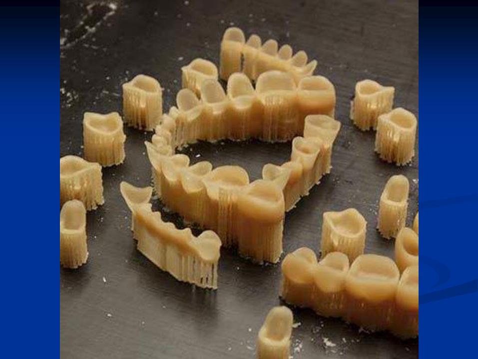
3-D Printing


Wax pro
150 wax copings per 8 hours

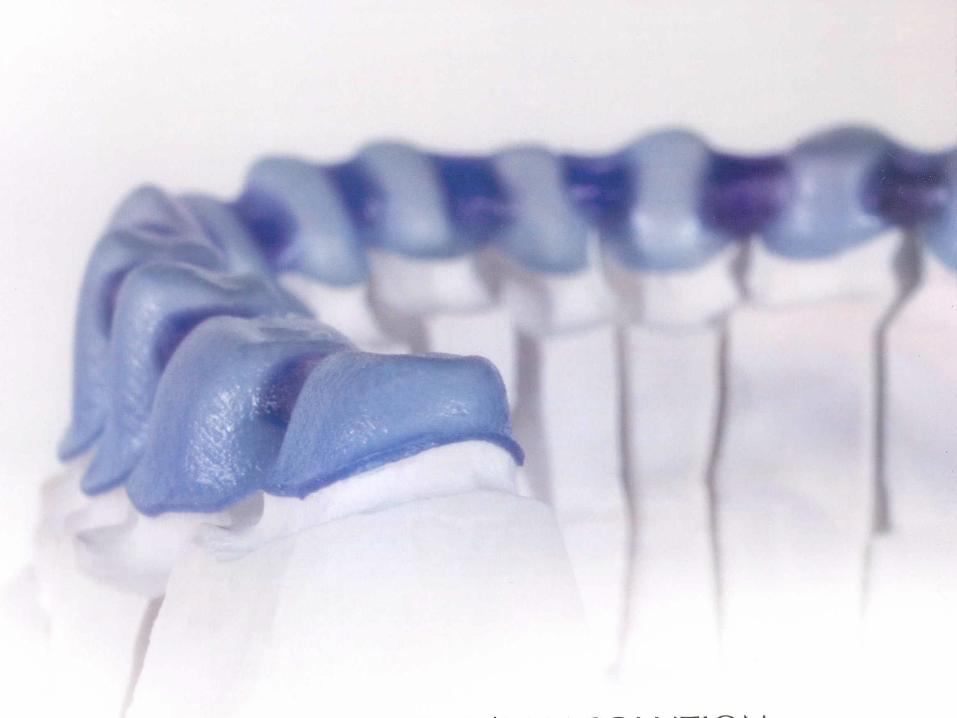
Neo
200 wax or resin copings per day
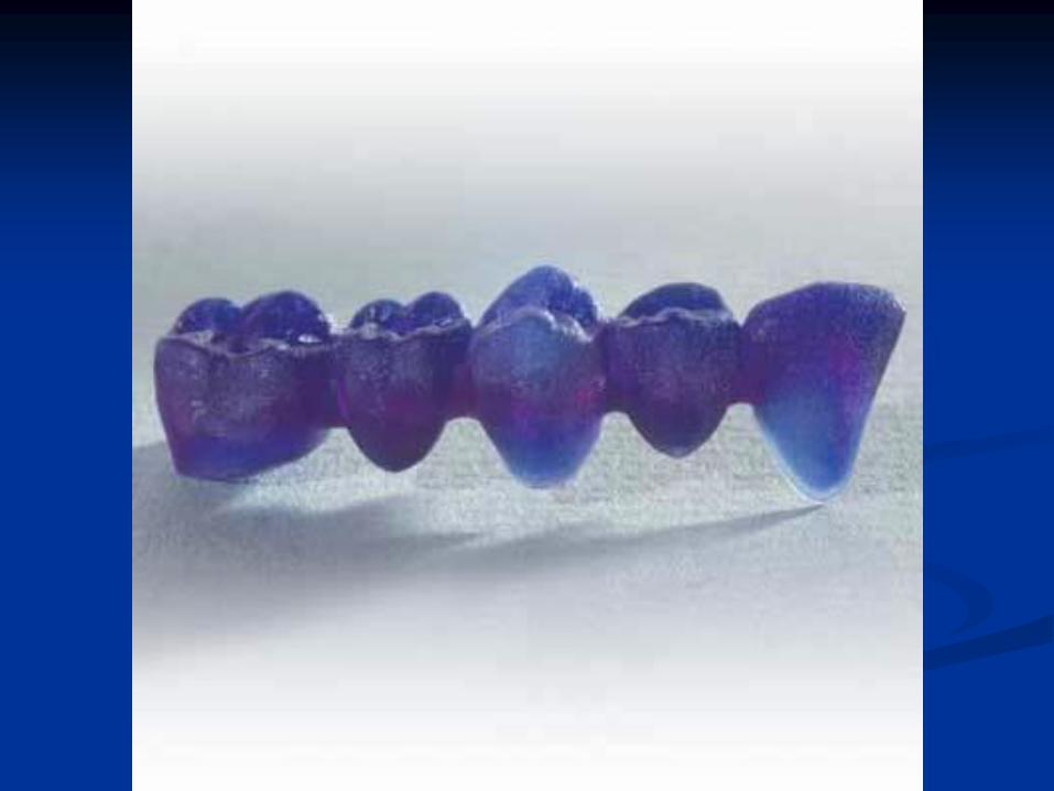
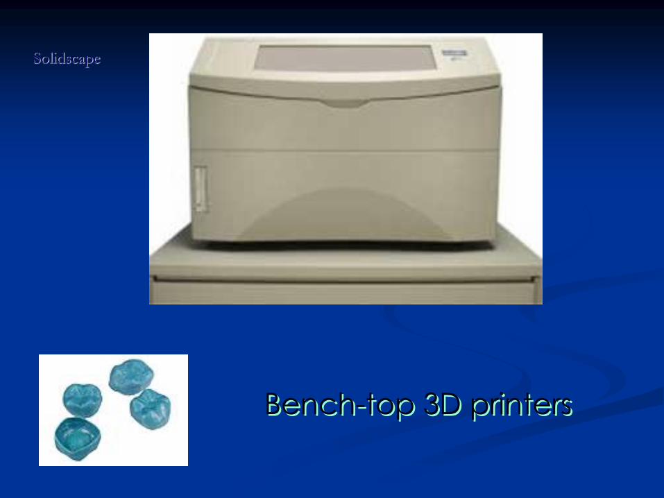
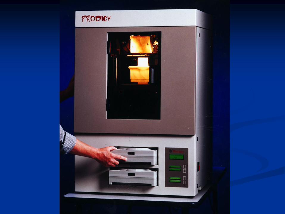
Bench-top 3D printers
Solidscape

Thank you