Embed Size (px)
Citation preview
ARR No. 3G26
NATIONAL ADVISORY COMMITTEE FOR AERONAUTICS
WARTIME REPORT ORIGINALLY ISSUED
JulyJ.943 as "iReport 3G26
WORKING CHARTS FOR THE COMPUTATION OF PROPELLER THRUST
THROUGHOUT THE TAKE-OFF RANGE
By Gerald L. Desmond and Robert F. Freitag Bureau of Aeronautics, Navy Department
NACA WASHINGTON
NACA WARTIME REPORTS are reprints of papers originally issued to provide rapid distribution of advance research results to an authorized group requiring them for the war effort. They were pre- viously held under a security status but are now unclassified. Some of these reports were not tech- nically edited. All have been reproduced without change in order to expedite general distribution.
W-100
NATIONAL ADVISORY COMMITTEE FOE AERONAUTICS
iREPORT
WORKIIG CHARTS FOR THE COMPUTATION OF PROPELLER THRUST
THROUGHOUT THE TAKE-OFF RANGE
3y Gerald L. Desmond and Robert F. Freitag
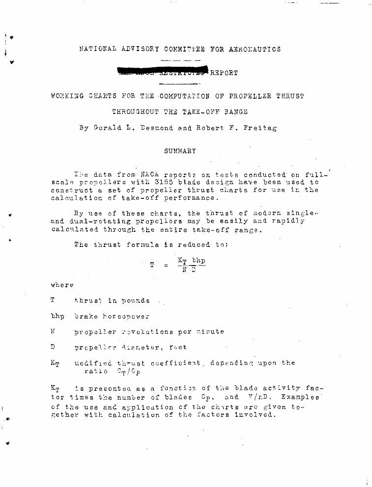
SUMMARY
The data from NACA reports on tests conducted' on full- scale propellers with 3155 blade design have been used to construct a set of propeller thrust charts for use in the calculation of take-off performance.
By use of these charts, the thrust of modern single- and dual-rotating propellers may be easily and rapidly calculated through the entire take-off range.
The thrust formula is reduced to:
T = ^TJL1^
N D
where
m a»
bhp
K
D
KT
Kj is presented as a function of the blade activity fac- tor times the number of blades Cp, and V/nD. Examples' of the use and application of the charts are given to- gether with calculation of the factors involved.
thrust in pounds
brake horsepower
propeller rovolutions per minute
propeller diameter, feet
modified thrust coefficient, depending upon the rai
INTRODUCTION * - •'
An accurate evaluation of propeller thrust requires a knowledge of many variables. Empirical analyses have "been developed "by The Hamilton-Standard Propeller Division, United Aircraft Corporation in I9U1 and "by The Propeller Division, Curt iss-Wr ight Corporation in 19*+0 for deriving correction factors to account for these variables. Gen- erally, however, these correction factors are compensat- ing and it appears that the use of the thrust and power coefficients with a correction for solidity only is suffi- cient for general application in the calculation of take- off thrust and consistent with flight-test accuracy.
For the "basic propeller data, the Hamilton-Standard propeller "blade design No. 3^55-° ^as "been used because the UfACA has tested this "blade in a wide variety of assem- blies ranging from three blades to eight blades for single- and dual-rotating propellers. Also, additional tests .were made with this blade section increased *0 percent in width. Thus a consistent set of propeller data covering a wide range of solidity is available. Por a measure of solidity, the activity factor of the blade multiplied by the number of blades is used. This combination provides an integra- tion of power-absorption capacity of the blade elements in addition to the propeller solidity;,
It has been found convenient in making take-off cal- culations to plot the propeller data as a modified thrust coefficient Kj, involving engineering terms as defined by Diehl in reference 1„
It is the purpose of this report to present these data for general use»
SUMMARY OF TESTS
The data used in the construction of the thrust charts were obtained from extensive tests conducted at the NACA 20-foot propeller-research tunnel and reported in detail in references 2 to 5«
Propellers
The propeller blades tested were the 3155-6 (right hand), 3l56-*5 (left hand), 3155-6-1.5 (right hand), and the 3156-5-1.5 (left hand),, Some additional data were incor-
porated from the tests of the 5868-9 propelle'r "blade as presented in reference 6, The diameters vere 10 feet and 9 feet for the propellers of the 3155 "blade design and the 5858 "blade design, respectively. Clark-Y "blade sections were employed throughout.
Body
The propellers vers tested on a test rig consisting of a streamline "body with provisions for mounting the pro- pellers in "booh the tractor and the pusher positions. In the charts presented herein, only tL.e data from the tests on the propellers in the tractor position are used. These data include the effect of.a symmetrical wing mounted in a midwing positior. set at 0° angle of attack. Spinners were used for all tests.
SYMEOLS
P Cp = ~> -oower coefficient
pn JJ
T CT '•- ö—7' thrust coefficient pn D
J = V/nD, advance-diameter ratio
P engine power, foot-pounds per second
T propeller.thrust in pounds
N rotational propeller speed, rpm
n rotational propeller speed, rpr;
D propeller diameter, feet
V airspeed, feet per second
p mass density' of air, slugs/ft3
Cm Kj modified thrust coefficient, 33,000 Q—
KJ modifiod static thrust coefficient
4
17 activity factor - lflgjjflfi j g) (£)* d (g
0.3
b propeller 'blade width at radius r
r radius of propeller "blade element
R propeller radius
METHOD OF PRESENTATION
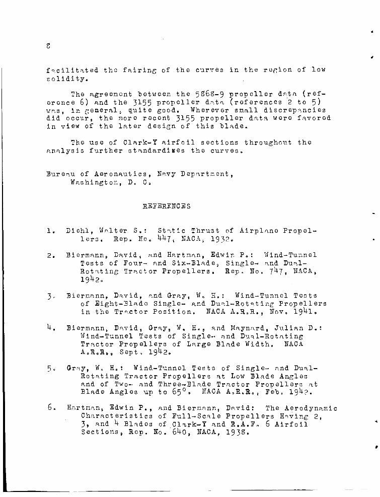
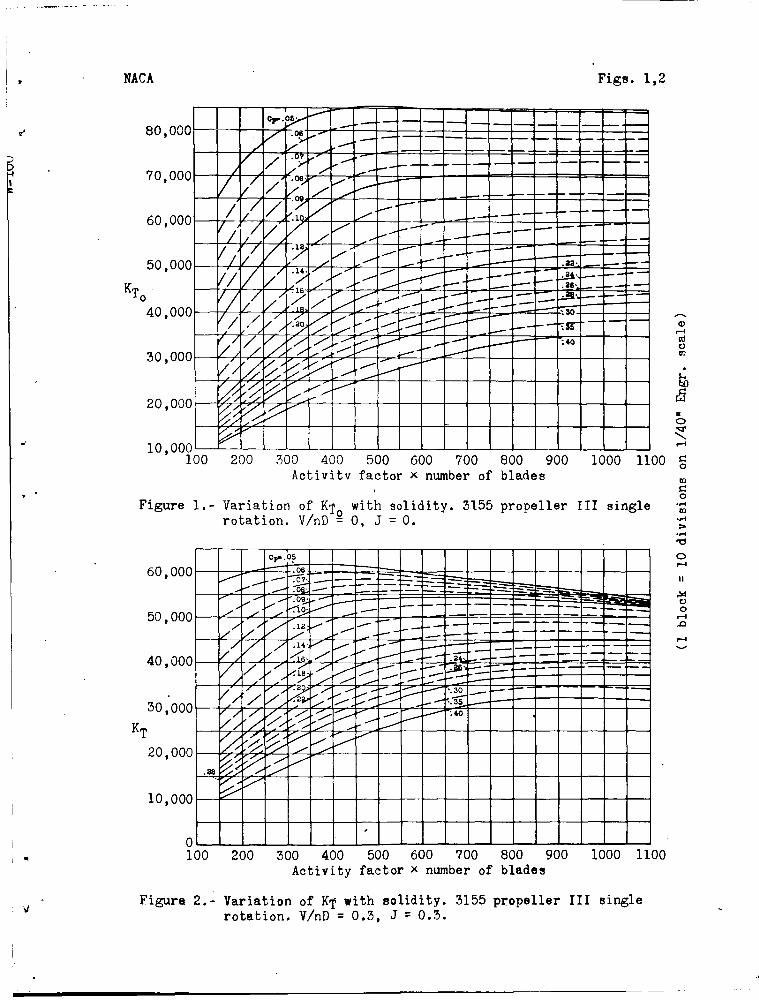
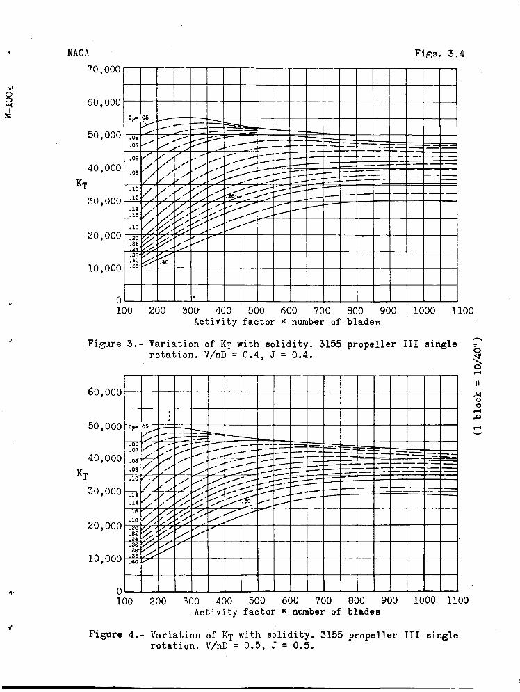
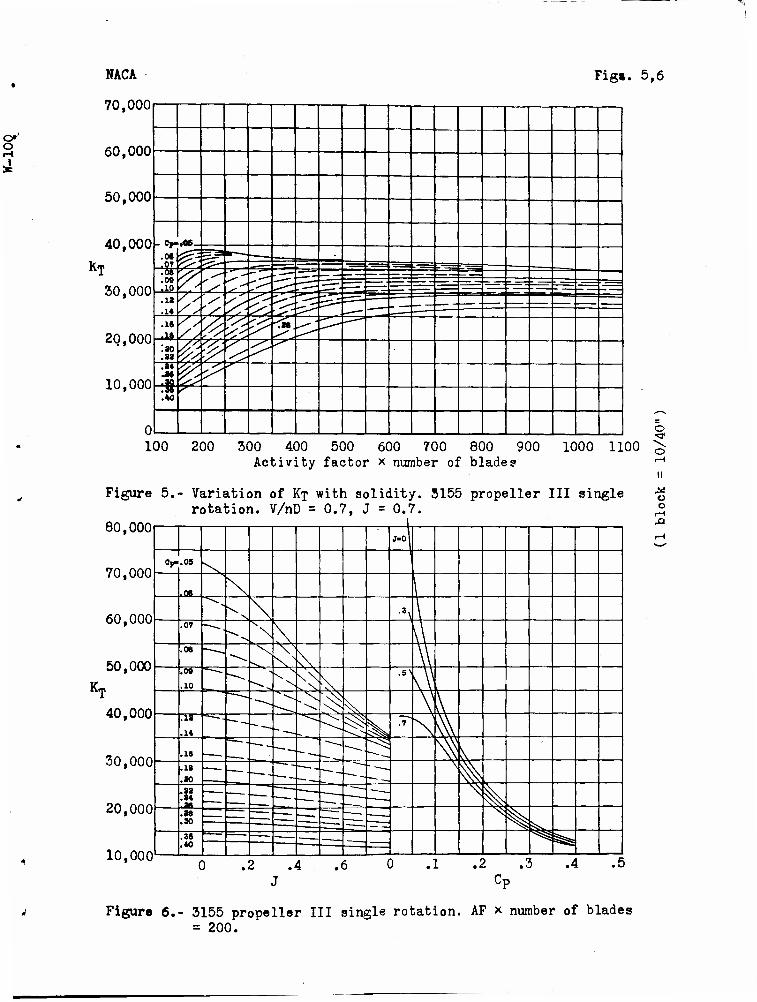
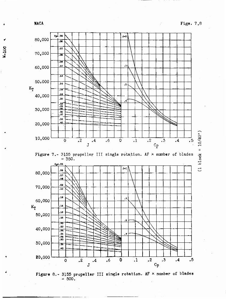
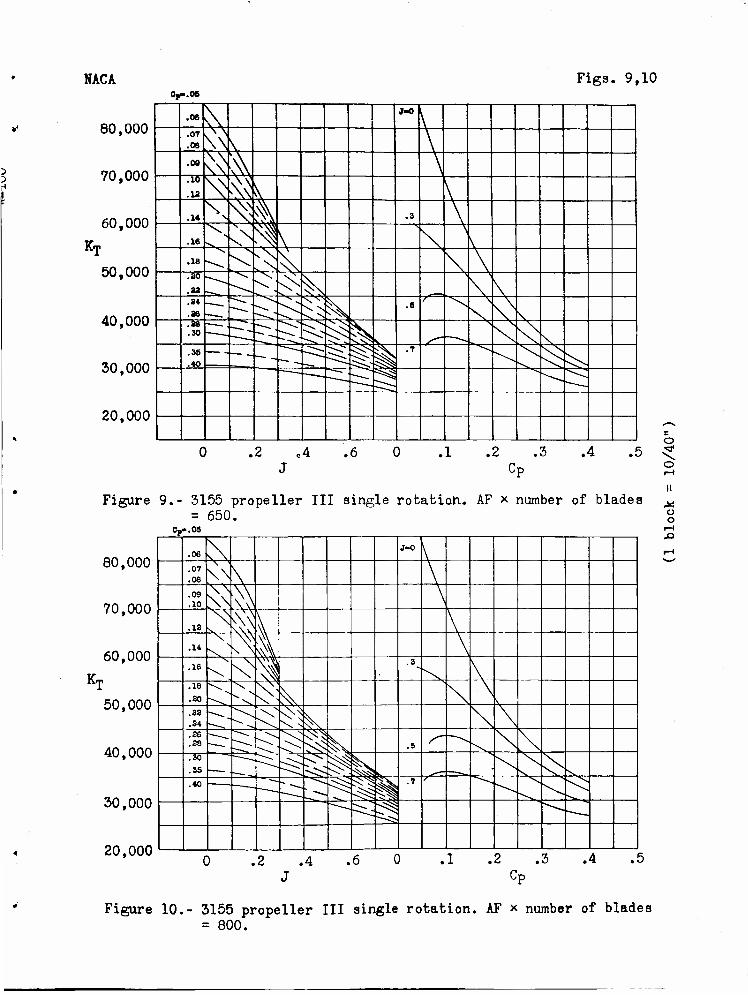
Curves of Kj against AF times the number of "blades, with varying values of Cp and J are presented in fig- ures 1 to 5 for single-rotating propellers and in figures 11 to 15 for dual-rotating propellers. Curves of Km against Cp with varying values of J and AF times the number of "blades and curves of Km against J with varying values of Cp and AF times the number of "blades are pre- sented .in figures 6 to 10 for single-rotating propellers and in figures 16 to 20 for dual-rotating propellers.
From references 2 to ^ values of Cp and dj' for the various "blade angles tested were obtained for each propel- ler and the thrust coefficients Km were computed. The available data consisted of curves of Cm and Cp against V/nP for "blade angles of 10° to 65°,
The propellers were tested at values of J as low as 0.3 and, in a few cases, to values as low as J = 0.2. The necessity then arose to extrapolate the curves Cp and Cm to the value of V/nD = 0, in order to obtain static thrust coefficients. In a small number of cases, extrapo- lations made by the NACA were included in the original data. These extrapolations, when available, were followed. Later, calculated curves of Cp and Cm against J were presented by the NACA wind-tunnel staff in an unpublished report. These calculated"curves were found to be in excel- lent agreement with the test data throughout the ranges in which they could be compared. It was then concluded that extrapolations of the test data, based on these computed curves, could be used. These extrapolations were most ac- curate at low-blade angles and low-powor coefficients. It is under these conditions that the propeller is operating near the maximum value of L/D. At the higher blade angles
f-ncl power coefficients, the variation of Kj with J is small, and small errors in the extrapolations will not materially offset the fairings.
Eecent unpublished data presenting outdoor static- thrust tests of the 3155-6 and 3155-6-1,5 blades show ex- cellent agreement with the static thrust data as presented in thi s report.
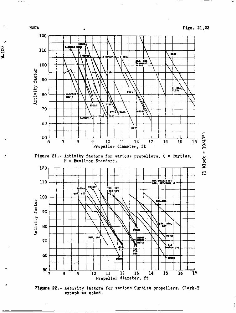
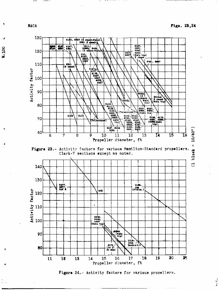
Thrust Calculation
The calculation of the thrust is simply performed. The activity factor of the "blade is obtained from the geo- metric characteristics of the blade. Curves of activity factor of a blade against propeller diameter for a large number of propeller blades now in use are presented in figures 21 to 24. The power coefficient Cp is computed from the engine and propeller characteristics. I1or a con- stant~speed propeller, this value of Cp will remain constant throughout the take-off range. 3Tor a fixed-pitch propeller, the value of Cp will vary with airspeed which necessitates additional calculations. In this case, a method similar to that outlined in reference n should be used. The value of the advance ratio V/nD is computed at the various speeds during take-off for which the thrust is desired. The value of Kj is then read from the charts or by interpolation between the charts. This is most easi- ly performed by reading figures 1 to 5 (or 11 to 15) and using figures 6 to 10 (or 16 to 20) to facilitate interpo- lation .
The thrust is then computed from the formula
Krp bhp T =
F D
The data from which these charts were derived were obtained in tests at relatively lew propellor tip speeds. Inasmuch as these charts were designed for a quick evalu- ation of the thrust during take-off, and the take-off dis- tance in turn is primarily affected by airplane drag, lift coefficient at take-off, and handling technique in addition to the propeller thrust, it is assumed that changes of thrust due to propeller tip speed are of sec- ondary order in take-off evaluation up to a tip speed of 10C0 feet per second at sea level. In order to avoid ex- cessive losses in propeller efficiency due to compressi-
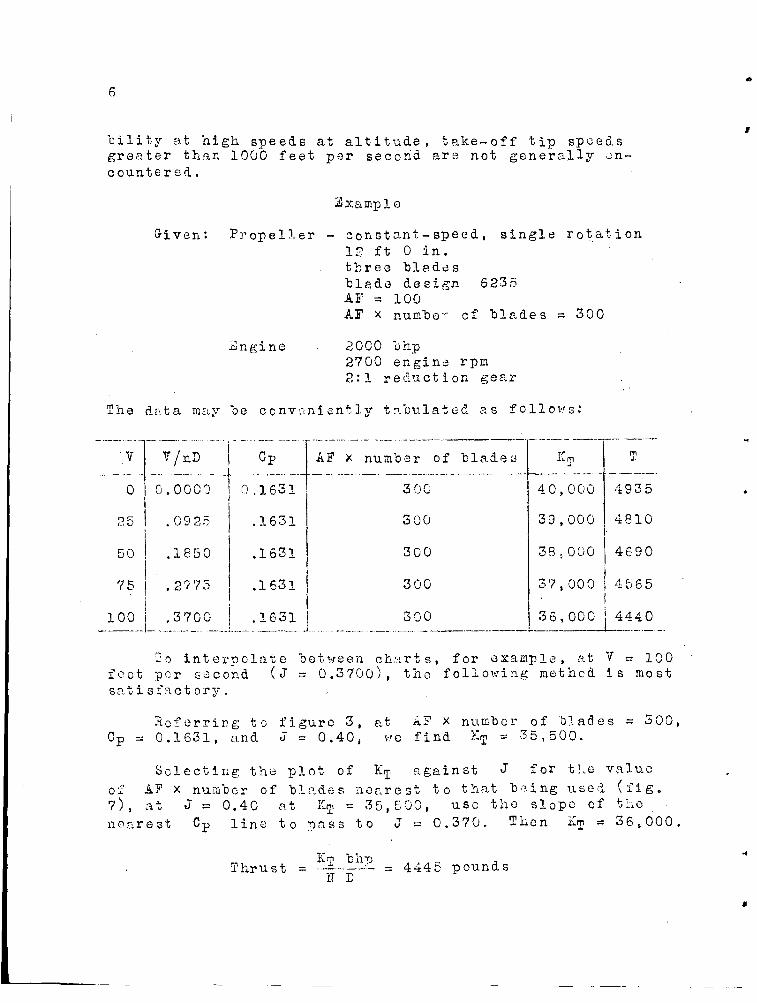
bility at high, speeds at altitude, take-off tip speeds greater than 1000 feet per second are not generally en- countered.
Sxample
Given*. Propeller - constant-speed, single rotation 12 ft 0 in. three blades blade design 5235 AF =100 AF x nunhe- cf "blades = 300
jsngme 2000 lihp 2700 engine rpm 2:1 reduction gear
?he data may "be conveniently tabulated as follows.*
0
50
75
100
V/nD
0.0000
.09 25
.1850
.2775
.3700
CP
0,1631
.1631
.1631
.1631
.1631
AF x number of blada a
300
300
300
300
300
I'M-P
40,000
39,000
38., 000
37,000
4935
4810
4690
4 5 6 5
36,000 ! 4440
lo interpolate between charts, for example, at V = 100 feet per second (J = 0.3700), the following method is most satisfactory.
Referring to figure 3, at AF x number of blades = 500, Cp = 0.1631, and J = 0.40, we find ET = 35,500.
Selecting the plot of KT against J for the value of A? x number of blades nearest to that being used (fig. 7), at J = 0.40 at KT = 35,500, use the slope cf the nearest Cp line to pass to J = 0.370. Then % = 36,000.
Km bh"p . , , _ •, Thrust = — = 444c pounds II D
To'find the thrust at V = 25 feet per second (J = 0.0925):
Heferring to figure 2, at AF x number of blades = 300, CP = 0.1631, J = 0.300, we find Km = 36,600.
Entering figure 7 at J = 0.300 and Km = 36,600, we use the slope of the nearest Cp line to pass to J = 0.0925. Then Km = 39,000.
Km bhp Thrust = -ti .p = 4810 pounds
N 1) y
DISCUSSION
The use of the activity factor as a parameter for rep- resenting solidity is considered desirable as this factor is a weighted measure of propeller solidity. The activity factor of the "blade is a nondiiaensional function of the propeller plan form designed to express the integrated capacity of the "blade elements for absorbing power. In a propeller the velocity of the air passing over the blade , element, and therefore its power absorption, is mainly a function of the distance of the element from the center of rotatien. This fact was not allowed for in the older form of blade-area function, the ratio of blade area to total disk area. The activity factor of the whole propeller is equal to the activity factor of the blade nru.lt iplied by the number of blades.
The high activity factors of the propellers were ob- tained by increasing the number of blades and by increas- ing the blade '.fidth. Although these two methods are not strictly comparable as a means of increasing the solidity of a propeller, excellent agreement was found throughout the regions that the twa methods coincided. This is in agreement with reference h, which concludes that increas- ing the solidity by means of increasing the blade width results in the same effect aB increasing the number of blades. Increasing the blade area by increasing the diam- eter had about the same effect as increasing the solidity, for equal tip speeds.
The plots represent a complete family of propellers of the 3155 blade design, from two to eight blades. The inclusion of the 5866-9 blade-design propeller data of reference 6 aided in the generalization of the charts and
facilitated the fairing of the curves in the region of low solidity.
The agreement "between the 5S6S-9 propeller data (ref- erence 6) and the 3I55 propeller data (references 2 to 5) was, in general; quite good. Wherever small discrepancies did occur, the more recent 3^55 propeller data were favored in view of the later design of this "blade.
The use of Clark~Y airfoil sections throughotit the analysis further s tandardis.es the curves»
Bureau of Aeronautics, Navy Department, Washington, D. C3
REFERENCES
1. Diehl, Walter S.: Static Thrust of Airplane Propel- lers. Rep. No. 1+4-7, NACA, 1932.
2. Biermann, David, and Hartman, Edwin P.: Wind-Tunnel Tests of Pour- and Six-Blade, Single- and Dual- Rotating Tractor Propellers. Rep. No. 7^7, NACA, 19^2»
3 >. Biermann, David, and Gray, W0 H, : Wind-Tunnel Tests of Eight-Blade Single- and Dual-Rotating Propellers in the Tractor Position. NACA A.R3R.f Nov. I9U1.
k. Biernann, David, Gray, W. H. , and Maynard, Julian D.: Wind-Tunnel Tests of Single- and Dual-Rotating Tractor Propellers of Large Blade Width. NACA A.R.R., Sept, I9U2.
5« Gray, W„ H.: Wind-Tunnel Tests of Single- and Dual- Rotating Tractor Propellers at Low Blade Angles and of Two- and Three-Blade Tractor Propellers at Blade Angles up to 65°, NACA A„E,E0f F eh. I9U2.
6. Hartman, Edwin P., and Biermann, David: The Aerodynamic Characteristics of Full-Scale Propellers Having 2, 3, and k Blades of Clark-Y and R.A.E„ 6 Airfoil Sections, Rep. No. 6^0, NACA, 193S.
NACA Figs. 1,2
3^ .06' r-"
j> /
.07
x- "
/ .08^ "%
/ / . /
'•10,
M / / s ./
_ __
'/ •^
f .S x"' •^ .33-,
// / />
•^ ^ '""'
.36v __„
'/ / /
/' s ""^ ~ — .4eC
^11
'.20, ^
or" -^ -~^ -Jsl / /
', '^ '-.•o
£ ^
't'/ '* ^
it ,/,
&
K.
80,000
70,000
60,000
50,000
40,000
30,000
20,000
10,000 100 200 300 400 500 600 700 800 900 1000 1100
Activity factor x number of blades
Figure 1.- Variation of Kf with solidity. 3155 propeller III single rotation. V/nD =0, J = 0.
60,000
50,000
40,000
30,000
r 20,000
10,000
0 100 200
Op-- D5
r-— Tor' .OJL,
-^ ^^ Ef rzm ^s ?S 3^ ?3D fe y' y~
y^ '.09;
<l0; ,—
S J
r s • . •12: y" " -~"'
\ / / /
.1«: V ,/ ^- ".2fc
/ /, ' y /
-^ ^ ^ JT JB,
Y' P"T20>
•JT; \30 -~~
/ £ ^ .s* ,-'' -^ ':40 •
^ s-^S
-^
.38 4' 0 * *,
^ ^y*
'
CO o CO
C
o 5f
C o m C o
• iH
> • iH X)
O
Ü o
300 400 500 600 700 800 900 Activity factor x number of blades
1000 1100
Figure 2.- Variation of Kf with solidity. 3155 propeller III single rotation. V/nD = 0.3, J = 0.3.
NACA Figs. 3,4
70,000
60,000
50,000
40,000
r 30,000
20,000
10,000
0
-Op- 05 -
.06
.07 ^ '^ - —
.08 yy S -- •^
.09 / , / „ s ^ —
.10
.13
' * \—^ ^
S • 'S rag> ^ "~~ .
.
.14
.16 /' ' s
/'' ' s • *«1
.18 '/• &
S s ^
^ ,.^J
.20
.22
.24' P ^ S j
.28"
.30
.35-
'/,- .'40
-
100 200 300 400 500 600 700 800 900 Activity factor x number of blades
1000 1100
Figure 3.- Variation of KT with solidity. 3155 propeller III single r rotation. V/nD = 0.4, J = 0.4. §
60,000
50,000 Op-.
i
05
.06 .07
' s ^r ~ =-':
40,000 -~ ~^^r — —
.08
.08 // V ^ -~^ ~^- .
.10
/, ',/ ^> 30,000 .13 .14 {/, 'S ^ rsS^
20,000
.16
.18
.20
.22
.24
//, K & ' '
1? s
10,000 .26 .28" £> .40 s
n
t) o
100 200 300 400 500 600 700 800 900 Activity factor x number of blades
1000 1100
Figure 4.- Variation of Kj with solidity. 3155 propeller III single rotation. V/nD = 0.5. J = 0.5.
Fig». 5,6
k-p
NACA
70,000
60,000
50,000
40,000
r 30,000
20,000
10,000
100 200 300 400 500 600 700 800 900 1000 1100 Activity factor x number of blades
Figure 5.- Variation of Kf with solidity. 3155 propeller III single rotation. V/nD = 0.7, J = 0.7.
80,000
70,000
60,000
-CF- .06 .0? ^ -1
.09
.10 ^ V •<* * -^. ^=
=•=
=^= —=rs Er=E .IS .14
X s. •^-'
.16 / s /J tt
"TM
.38 % M 3 .a* •it
% \s^ .U .to <
o
o o
50,000
K„
40,000
30,000
20,000
10,000
j-ol
Of .05 x .06
^~ N ''i .07
V
V 1
\\ .08
^ V v\ \\
.09
.10 ^ * v S .\
•s>
\\ i .N 3 \ \ V .13
.14 ^ §s
.7 >
^ .16
^- ^~- \1 ^ .18 .80
^> i .83 .34 an
\ % >..
.88
.30 — ^ ^n - ~~_ > %
.36
.40 — — ^
C ) . 2 .' 4 .< ( 3 • L t I ^ 5 .t- I .5 Cp
Figure 6.- 3155 propeller III single rotation. AF x number of blades = 200.
NACA Figs. 7,8
Kr
80,000
70,000
60,000
50*000
i
40,000
30,000
20,000
10,000
er .06 \
, •7*0
I .06
\N \ \ .0?
\: N\ \ .06 \ \S \ \
.09
.XO \ "
^ \, .3 \
\ X \ \ \
.13 ^ Ni
\, A .14
~^ % \ .5 V .16
.18 ^"~ ^N \\ \
.20 ^O^ ^ .7" \\
.33
.34
.26 • ^r H^ ^ '^
.36
.30 ^ Z^ ^ ^ s
.35
.40
" ^
^ ^j
0 .2 .4 .6 J
0 .1 .2 .3 .4 .5 Cp
Figure 7.- 3155 propeller III single rotation. AF x number of blades = 350.
80,000
o 5*
o o
70,000
60,000
50.JOOO
40,000
20,000
er .06
.06 s\ J-0
\ .07 .08 \^ \ \
.08 V
^ \ .10
^ \ .18 \
\\ i • 3 \ .14 \
^ A .16
V > NN V
.18 ^v
^ .5 \\ .20 .22
^1 [^ >, N
.24
.26
.28
.30
5 C: s/v ^ & (N .7 \
rr: ; V \ .35
.40
" •— == X
^
30,000 -—:3s- — —
0 .2 .4 .6 J
% C» • Q ***• • v
Figure 8.- 3155 propeller III single rotation. AF x number of blades = 500.
NACA Figs. 9,10
Ki
Oy.06
80,000 .06
\ J-0
\ .07 .08 ^ \ \
70,000 .08
^ >\ \ .10 .18 ^ •^ \
60,000 .1« \ k .3 \
.16 X
v> \
\ \
V
50,000 .18
^s.
\ .80
.33
•^ V
^ x 3v^ N \
40,000 .34 .36
—• ^ ^ ^ N ^S
.6 N\ .88 .30 ^ ^ - . X<\
30,000 .35 .40 --^ i^i c^^ P .7
>^ ^fc/^
20,000
.2 o4 .6 J
Km
.1 .2 .3 .4 .5 < fr, °
II Figure 9.- 3155 propeller III single rotation- AF x number of blades ^
= 650. g Cp».05
80,000
70,000
60,000
50,000
40,000
30,000
20,000
.06 ^
J-0 \
.07
.08 W \ \
.09
.10 ^ ^> \
.12 ^ k ^ \ \
.14 \ ^ ä \
.16 V \\ i .3^
\ .18 .80 i^- ^ v\\
\
.38
.84 \i \
.26
.88 ^r "N^N i \ .5
.30
.35 . <>" ^
.40 ^-^s
^ In .7 vT^i
^
. .2 .4 .6
J • X • C» • O «4 • U
Figure 10.- 3155 propeller III single rotation. AF x number of blades = 800.
Figs. 11,12
20,000
100 200 300 400 500 600 700 800 900 Activity factor x number of blades
1000 1100 o 5*
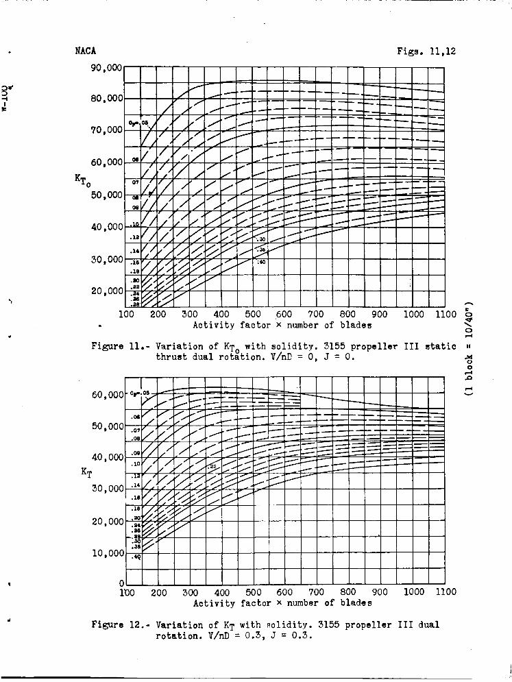
Figure 11.- Variation of KT with solidity. 3155 propeller III static thrust dual rotation. V/nD = 0, J = 0. o
o
lt>0 200 300 400 500 600 700 800 900 1000 1100 Activity factor x number of blades
Figure 12.- Variation of K-p with solidity. 3155 propeller III dual rotation. V/nD = 0.3, J = 0.3.
K<v
NACA
70,000
60,000
50,000
40,000
r 30,000
20,000
10,000
100
Figure 13.-
70,000
60,000
50,000 -
40,000
r 30,000
20,000
10,000
0
Figs. 13,14
c,-.c f .
.0« /' ' s ' ^
^-= —
.0« • ^ —
.OS
.10 // 'A /* y
.IS /, y ^
^ <."<• .14
.16 '/y. £ '<£ ^^ *.Q y
.18
.30 V>' '& ^
.21
.34
.36' '# 't> -y
.30-
.36
.40 ^>
200 300 400 500 600 700 800 900 1000 1100 Activity factor x number of blades
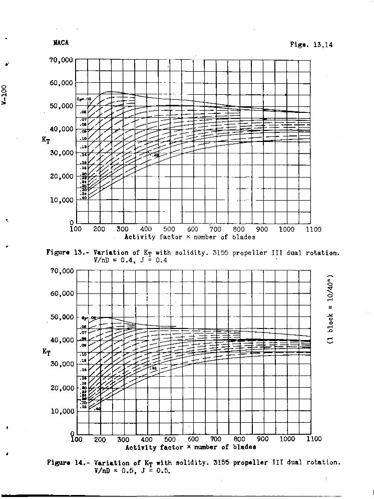
Variation of K-p with solidity. 3155 propeller III dual rotation. V/nD = 0.4, J = 0.4
o
o o
Kq
•r .06
===== .07 .N y^.
5^ • —~ — =£1
.09 y y „ y „ ^r. Z
, ' •=zs
.13 ,/, -?*-.
y"t " j*-
.14 'ff '<<•
" > K& ^- .1« .18
-.30 .33 .34
.TO-
.35
% <# -y^ <^^ sy
'<£
100 200 300 400 500 600 700 800 900 1000 1100 Activity factor * number of blades
Figure 14.- Variation of Kf with solidity. 3155 propeller III dual rotation. V/nD = 0.5, J = 0.5.
MACA Figs. 15,16
o o
-A
Kn
YU.UUU
60,000
50,000
40 000
•9S i 30,000
.6?
.08
.09 y. ' / i H=
.10
.12
.14
.16
.18
/' 's*
^
20 \000 v. § '&.
-^^
.30
.33 P -^ ^^
10,000
.38
.3a
.35 ^
.40
o 1C 0 2C )0 3C »0 40 0 50 0 60 0 700 800 900 1000 1]
Activity factor x number of blades
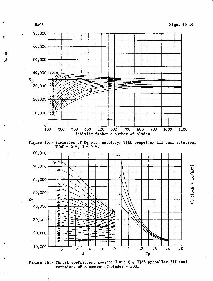
Figure 15.- Variation of K-p with solidity. 3155 propeller III dual rotation. V/nD = 0.7, J = 0.7.
80,000
o
M a o
Figure 16.- Thrust coefficient against J and Cp. 3155 propeller III dual rotation. AF * number of blades = 200.
NACA Figs. 17,18
3 3
K,
80,000 •2 » N J-0
\ .06
,07 V \ \ t
70,000 .06 \
\^ \ .09 NN sV V. .3 \
60,000 .10
^ s\
^ s
\ .ia
s^ \ \
50 000 .1« ^
\ ^ K \ \\
.16 -J \ *v "" $ s .5
\ \
40,000 .16
.30 ^ \ \\
.33
.34 —_ -^
^ ?^> <7 \
30,000 .36 .38
' r^ ^ vV \
- .30
.35 ^ ^^
.40
20,000
3 . < ? .1 1 .t ( D • r 2 <> .L .5 J Cp
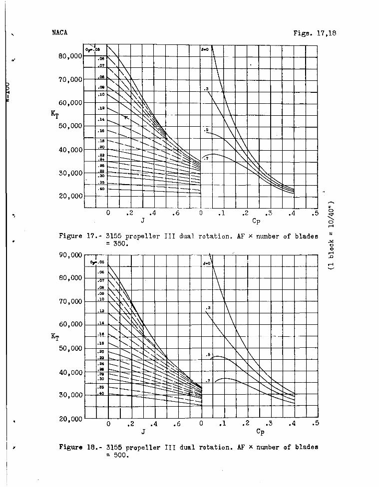
Figure 17.- 3155 propeller III dual rotation. AF x number of blades = 350.
o •5*
A4 o o
20,000 0 .2 .4 .6
J
Figure 18.- 3155 propeller III dual rotation. AF x number of blades = 500.

Figs. 19,20
20,000
Figure 19.- 3155 propeller III dual rotation. AF x number of blades " = 650.
KT
90,000
80,000
70,000
60,000
50,000
40,000
30,000
20,000
o o
\ - Cp"
.06 \
J-0 \
.07
.08 ^ \
.09
.10 $ \ \
.13 ^ ^ k \
.14
.18 \^
^ k \ v
.18
.30
^\ s \ .3 N .33 .34
^ ^s N » .36 .38 ^
"O* § 58 *k .30 .35 •^.
>> i .5 s- .40 ^ -c fe •s^
,7 ,s ^
^ ~-5§
0 .2 .4 .6 J
.1 .2 .3 .4 .5 Cp
Figure 20.- 3155 propeller III dual rotation. AF * number of blades = 800.
NACA Figs. 21,22
120
110
100 o
•p o ,* 90 «H
-P
> •iH -P
80
70
60
50
1 V \
0-M iM * L
IM \ \ \
1
\
\ \- A i\ - H-MO»- L_ C-5580 \ V«Mt
y \ \ 0 v \ ! 1 •g. IHW »44-6
"i
j,*k \\ \ \\ \ A <
\ \\
\ \ \\ \\ 0 \N \ \ v V > ü V \
>
1 \\ V \ I. Stc 163*
V \
\ \ \ \ \ \ \ s «4-^ \ \
I
'\ tur ft
\ 1 \ \ \
V \)
\)
v \ V 768^ l \ 1 *\
\
\ 570-
5923
\. 188 \ 8t03 \\
0-651 Boi-^y
\ \
\ 817 1
6 9 10 11 12 13 Propeller diameter, ft
14 15 16
c O
Figure 21.- Activity factors for various propellers. C = Curtiss, H = Hamilton Standard.
120
110
100 u o
& 90
-4J
M t) O
U
U4- »ukl ••7-
• «-T MOA
8 1301- 893 io\
786, IA0A
Pi 787 tip
•M, 1*
•M, «53
^ V v s \
\ \ vN \ \ !\ ^
N, 4-M
\ \ \ \ \
^
N
\.
\ s VN >
V \ ^
' \
N V 1 M \V ffr U*. \
\ ^
w k «4
sia , 951 V >
V •no \s 0s •MM
\ i
M tttii \
1, 1 -•14 twtki« c-y
1 m
\ - MMI
N
. . .. 11.11
80
70
60
50 7 8 9 10 11 12 13 14 15 16 17
Propeller diameter, ft
Figur« 22.- Activity faetors for various Curtiss propellers. Clark-Y except as noted.
NACA figs. 23,24
130
Propeller diameter, ft
Figure 23.- Activity factors for various Hamilton-Standard propellers. Clark-Y sections except as noted.
o 5>*
o Y
140 \
\ \
130 \ v,
\ MT - Or
Mr f. HI N-
2 120 o «d
> \ •30 - " IM 'u.) \
£110 •IH
*
V ^«
3 100 •s •4 t».
^ V N
8*97 ~ (»AC» tip)
\ Y
90
' ^
ttm S. (l
IB IA0« J
"s \c 101 •-X
80 «r r» A
17 ^ V \ Ml» ^1
•rv ft 4U)
\ > 1 1 1 2 1 3 1 4 1 5 1 5 1 7 11 3 1< ? 2( ) 21
Propeller diameter, ft
Figure 24.- Activity factors for various propellers.
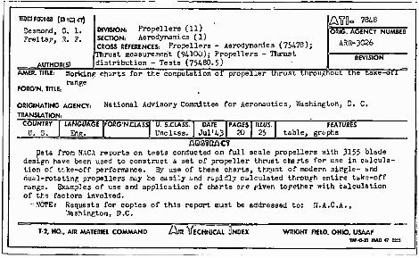
ranfoass (OKasr) Desmond, G. L. Freitap, R. F.
AUTHOR(S)
| DIVISION: Propellers (11) SECTION: Aerodynamics (1)
JcROSS REFERENCES: Propellers - Aerodynamics (75478); (Thrust measurement (94300); Propellers - Thrust (distribution - Tests (75480.5)
ÄffO- 7848 ORIG. AGENCY NUMBER
ARR-3G26
REVISION
AMER. TITLE: Working charts for the computation of propeller thrust throughout the take-on range
FORG'N. TITLE:
ORIGINATING AGENCY:
TRANSLATION:
National Advisory Committee for Aeronautics, Washington, D. C.
COUNTRY
u. LANGUAGE
Eng I :ORG'N£USS| U. S.CIASS. Unclass.
DATE Jul'43
PAGES 20
ILLUS.
25 FEATURES
table, graphs QBSVQACV
pata from NACA reports on tests conducted on full scale propellers with 3155 blade design have been used to construct a set of propeller thrust charts for use in calcula- tion of f-ke-off performance. By use of these charts, thrust of modern sirgle- and dual-rotating propellers may be easily =nd rapidly calculated through entire take-off range. Examples of use and application of charts are piven together with calculation of the factors involved.
••NOTE: Requests for copies of this report must be addressed to: 'J.A.C.A., Washington, D.C.
T-2, HQ., AIR MATERIEL COM^ND "ÄBVI ECHNICAl UNOEX WRIGHT FIELD. OHIO. USAAF W^OM HAU 47 «3