Embed Size (px)
Citation preview
IAEA-IWG-NPPCI-96/3LIMITED DISTRIBUTION
WORKING MATERIAL
MODERNIZATIONOF INSTRUMENTATION AND
CONTROL SYSTEMS IN NUCLEARPOWER PLANTS
REPORT OF AN ADVISORY GROUP MEETINGORGANIZED BY THE
INTERNATIONAL ATOMIC ENERGY AGENCYAND HELD IN VIENNA, AUSTRIA, 25-29 MARCH 1996
Reproduced by the IAEAVienna, Austria, 1996
NOTEThe material in this document has been supplied by the authors and has not beenedited by the IAEA. The views expressed remain the responsibility of the namedauthors and do not necessarily reflect those of the government(s) of the designatingMember State(s). In particular, neither the IAEA nor any other organization or bodysponsoring this meeting can be held responsible for any material reproduced in thisdocument.
VOL 2 7 &§ 2
Table of Contents
Meeting Report
Extended outline of a technical document on "Modernization of Instrumentation andControl Systems in Nuclear Power Plants"
National presentations
3.1 Activities Related to the Modernization of Instrumentation and ControlSystems in the United States at the Electric Power Research InstituteJ. Naser, U.S.A.
3.2 C&I Refits on AGR'sR. Clarke, U.K.
3.3 Modernization of the Ukrainian VVER-1000 NPP Instrumentation and ControlSystemsM. Yastrebenetsky, Ukraine
3.4 Main Trends of Activity on Modernization of I&C Systems at NPPs in RussiaA.B. Pobedonostsev and A.G. Chudin, Russian Federation
3.5 Replacement of I&C Systems in WWER-1000 of Kozloduy NPPV. Miliovsky, Bulgaria
3.6 NPP I&C System Innovations in the Czech Republic. A RegulatoryPerspectiveC. Karpeta, Czech Republic
3.7 Modernization of I&C: A Stepwise Learning Process with a Final Vision.Paul van Gemst, Sweden
3.9 French ReportDall'Agnol, France
3.10 Ageing Diagnosis, Prediction and Substitute Strategies for I&CR. Heinbuch, J. Irlbeck and W. Bastl, Germany
4. List of participants
NEXT PAGE(S)left BLANK
-1-
MEETING REPORT
The need for frequent backfitting of instrumentation and control systems arises fromspecific conditions such as: rapid obsolescence of technologies as a consequence of whichnew designs with new operational characteristics have to be employed; the high potential forimproving and broadening I&C application to achieve improved on-site operational benefitsat relatively low cost; and new regulatory requirements.
The reasons for upgrading the instrumentation and control systems in nuclear powerplants are to take advantage of modern technology to improve plant availability and to reduceinstrumentation and control's contribution to escalating operating and maintenance costs.Modern instrumentation and control technology, using analogue and digital equipment to thebest advantage, brings increased reliability, safety and cost-effective plant operation.
The Advisory Group Meeting on "Modernization of Control and InstrumentationSystems in Nuclear Power Plants" was held in Vienna, Austria, from 25 to 29 March 1996and was attended by 21 experts from 14 countries. The meeting was organized jointly by theDepartment of Nuclear Energy and the Department of Nuclear Safety.
The objectives of the meeting were:
• To solicit and analyze information from Member States regarding their experience inmodernization of I&C in nuclear power plants.
• To identify requirements for the system modernization.
• To initiate the development of an IAEA TECDOC on "Modernization of I&C inNuclear Power Plants"
• To consider and approve the Objectives of the TECDOC.
5. To prepare the extended outline of the TECDOC.
The new technical document on the subject has to be produced as a consequence ofthe recommendations of the International Working Group on Nuclear Power Plant Controland Instrumentation to produce a guidance on NPP C&I modernization.
The participants agreed to the fact that the new technical document has to help plan,develop, and implement I&C systems for operating nuclear power plants, help develop costeffective approaches in qualification, verification and validation to address regulatoryapproval for new (digital) systems, guide for research and development of advancedtechnologies for improvements of safety, reliability, and productivity of present and futurenuclear power plants.
~Lf-
The time schedule for the preparation of the first draft of the report was agreed as follows:
1) Material from the Contributors to Technical Leaders: 15 June 19962) Material from Technical Leaders tot he Project Leader: 15 August 19963) First draft report to the IAEA: 15 October 19964) Draft report to the project team members: 15 November 19965) Next meeting: 2-6 December 1996
The participants of the meeting suggested that the technical report should be publishedas a TECDOC and distributed to all nuclear utilities in Member States as well as to maindesign organizations.
The extended outline of the document was prepared and further responsibilities of thetechnical report were discussed and agreed upon (see Table 1).
J
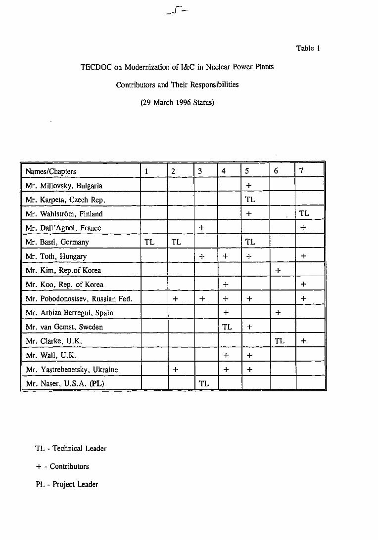
Table 1
TECDOC on Modernization of I&C in Nuclear Power Plants
Contributors and Their Responsibilities
(29 March 1996 Status)
Names/Chapters
Mr. Miliovsky, Bulgaria
Mr. Karpeta, Czech Rep.
Mr. Wahlstrom, Finland
Mr. Dall'Agnol, France
Mr. Bastl, Germany
Mr. Toth, Hungary
Mr. Kim, Rep.of Korea
Mr. Koo, Rep. of Korea
Mr. Pobodonostsev, Russian Fed.
Mr. Arbiza Berregui, Spain
Mr. van Gemst, Sweden
Mr. Clarke, U.K.
Mr. Wall, U.K.
Mr. Yastrebenetsky, Ukraine
Mr. Naser, U.S.A. (PL)
1
TL
2
TL
+
+
3
+
+
+
TL
4
+
+
++TL
++
5
+
TL
+
TL
+
+
+
++
6
+
+
TL
7
TL
+
+
+
+
+
TL - Technical Leader
- Contributors
PL - Project Leader

Technical Documenton
MODERNIZATION OF CONTROL ANDINSTRUMENTATION SYSTEMSIN NUCLEAR POWER PLANTS
Extended Outline prepared by the AGM Meeting held inVienna, Austria,
25-29 March 1996
1. INTRODUCTION
This report has been produced in response to the perceived need for collectiveconsideration of the issues and approaches to plant modernisation that is becoming necessaryas many operating power reactors approach their 20th to 30th year of operation. The needfor the activity, particularly for Instrumentation and Control systems was indicated by theIWG during its general meeting. Further discussion of the topic at Garching confirmed thisneed and international support that would be available for such an activity.
The report attempts to address a very wide range of circumstances from, old plantoperating at very low powers that face major ageing issues, to new potentially highperformance plant for which it has been decided I&C improvements are required to resolvesafety issues. The process of change raises many issues as to what potentially might beachieved by such a change to overcome obsolescence, economic and safety problems. Thereport must also include appropriate consideration of the increasingly international nature ofthe instrumentation and control system supply industry. Consequently it does not ignore thedifferent national approaches that are used to demonstrate the systems are suitable to bebrought into service. The report does not seek to provide advice on how the different nationallicensing processes should be approached.
The audience for the report is all those considering Instrumentation and Controlsystem change. It is hoped that by identifying the issues and giving examples of cases wherechange has been successfully achieved and indicating where and why difficulties have beenencountered, that others starting on such changes can benefit from experience.
The report is structured to follow the probable lifecycle of a modernisation exerciseand thus starts by considering the things driving change and the strategy to be adopted tomake the change. Thus chapters 2 and 3 of the report includes a discussion of continuedmaintenance of ageing equipment, as well as issues such as choice of technology if theconclusion is that change is required. The engineering issues are discussed in chapters 4, 5and 6. These examine the process from initiation to commissioning on the plant andidentifies some of the issues arising from choice of technology. Chapter 7 discusses humanissues, this is considered to be particularly important as if the change is not managedcorrectly then many benefit could be lost indeed the change may be detrimental to plantoperation. The issues treated in this section include the management of the old and newequipment on the plant and the very different interface it has to the operations andmaintenance staff.
- f -
2. PRESENT SITUTAION AND THE NEEDS FOR MODERNIZATION
The present situation is that many reactors are approaching mid life and some of thesystems particularly vital instrumentation and control systems are approaching the end of theirlife. The plant operators are faced with crucial decisions as to the strategy for continuedoperation of the plant, recontinued system maintenance, system replacement or systemupgrade. These decisions are to be made in an increasingly competitive environment aselectricity supply is deregulated and so enhancement of plant performance as well asachieving cost reduction becomes paramount.
In practice the situation is different from one plant to the other, so that the aspects forrefurbishment vary in priority. Some typical examples may demonstrate the basic differences:
Ageing: Towards the end of the life time (for I&C typically 20 years) more inspectionand repair work has to be performed in order to keep the necessary reliability of thesystem. Furtheron the original vendor may not produce any more systems of the oldtechnology or may have disappeared from the market. Though partly powerfulworkshop installed on-site, and partly special vendors are financed by the utilities, asituation like this causes rising maintenance costs and moreover the risk of spare partdelivery, so that an exchange of the concessed systems becomes highly necessarydespite the fact that the availability or safety targets are still achieved.
Quality Assurance: Adequate QA plays an important role for high integrity systems.For older systems - regardless of their real quality - this vigorous QA process ismissing or the quality of documentation does not meet the standard of today. In thiscase the lack of confidence in the quality of systems which are applied in sensitiveareas of the plant provide the prime impact to the decision for modernization. Thosedecisions mostly go along with the expectation of an improved availability.
Progress in technology. Computer-based digital I&C systems have many advantageswhen compared with the analogue technology. Performing of complex calculations,high flexibility and easy adaption to later changes are basic advantages. Extended self-testing during operation reduces the amount of manual repetitive testing, can make thebest coverage more complete and reduces the potential for human error. Improvementof MMI not only comprises the use of screens in the control room, but also thepresentation of complex situations by means of specialized graphs and diagrams. Inall this there is a gain of functionality which in many cases drives the decision forimproving I&C systems.
Operator support systems / diagnosis systems, methodologies developed for operatorsupport, e.g. SPDS, success pass monitoring, or for diagnosing the mechanical healthof the plant, e.g. loose parts monitoring, vibration monitoring, can be realized in aneffective manner by means of computer based systems only. They offer a vast fieldof providing useful information to the operator and making the operation of a plantmore effective and safer. These systems are most of the time stand-alone systems,they are comparably loosely coupled to traditional existing I&C and hence are add-ones which do not call for extensive installation efforts.
Sensors and actuators. Protection systems have to be tested repeatedly with great care,with a special issue being the demonstration of the accidental resistance of theconcerned components. For this purpose special test procedures have to be applied,e.g. by taking specimens from the relevant components of the plant and performingtests reproducing the stress under accidental conditions or to test components in situby means of special procedures like spray testing etc. It is important to note that bymeans of these procedures, relevant faults can be timely detected and repaired;moreover an insight into the overall status of these components is achieved whichultimately determines the decision if replacement by new items has to be performed.
In summary, most of the time it is a combination of the reasons given above, whichlead to the decision of modernization. Safety issues are not the prime motivation forconsidering a large refurbishment, it is rather system obsolescence, the reducing availabilityof spare parts and the potential gain in system performance and functionality which drive theutilities' decision towards application of modern I&C technology in existing plants. Thecompletion of such a change will bring safety benefit as reduction of operator action fortesting, and repair will reduce the number of human errors and potential challenges to thesafety systems.
3. STRATEGY
Instrumentation and control systems in nuclear power plants need to be modernizedin a systematic, reliable, and cost-effective manner to replace obsolete equipment, to reduceoperations and maintenance costs, to improve performance, and to enhance safety. Toachieve the maximum benefits from I&C modernization, it is important for the utility todevelop long-term planning and implementation strategies which include the definition of thevision for the plant at the end of the planning horizen. The strategy will be to look at theI&C systems in the context of the entire plant to determine which ones should be maintained,replaced, or upgraded. The strategy will prioritize the I&C modernization activities. It willidentify the infrastructure required to implement the modernization so that the vision will beachieved in a systematic manner.
3.1. GENERAL APPROACH
As the problems mostly arise at the maintenance level of the given I&C system orcomponent, the utilities, in the past, have tended to handle the question on that particularequipment without taking into consideration the plant as a whole. It is important to makemodernization decisions based on the overall vision for the plant so that a particularmodernization supports that vision.
comprehensivesystematiclife cyclereasons for this approachgoals to be reachedbased decisions on justifiable argumentsparticipants involved
3.2. CURRENT STATE OF I&C SYSTEMS IN PLANT(information obtained here will be useful for the future requirements)
Since their commissioning, I&C equipment have been modified. It is necessary toknow precisely the present state of the I&C systems and their operating history in order tomake appropriate decisions for the modernization of them,
definition of the I&C systemscollect documented information to support the decisions (adequacy and quality)description of I&C systems (limits, boundaries, environment, location, powersupply, grounding, operating characteristics, suppliers supports, ...)
3.3. PLANT POLICIES AND EXTERNAL REQUIREMENTS
The main goal of the plant policy is to cost-effectively produce power throughincresing power production, decreasing O&M costs, and enhancing safety. The plant policywill identify the goals and objectives of the utility that will effect I&C modernization. Theexternal requirements that effect l&C modernization must all be identified. This combinationof plant policy and external constraints will determine the plant vision and drive themodernization activities.
other projects presently ongoing and planned (safety reassessment, firesectorization reassessment, ...)long term business plan objectivesexternal requirements (regulatory issues, load following capability)
3.4. UTILITY DEFINED CONSTRAINTS
There are several constraints defined by the utility internally that must be satisfied bythe I&C modernization activities. These constraints must be identified and satisfied in theimplementation plans for I&C modernization.
develop plant specific guidelines for consistent modernizationstepwise versus global modernizationphysical constraints (including technological constraints)economic constraintssafety constraintstechnology constraintshuman constraints
3.5. DEFINITION OF VISION FOR I&C SYSTEM
A global vision of the overall future I&C configuration is to be defined at thebeginning of the modernization activities in order to coordinate the activities and theimplementation of the new equipment. I&C modernization can effectively be carried outduring several years based on the needs and constraints of the utility. This global visionincludes foreseeable new functionality to support the goals for the plant. It includesconsideration of the MMI, system boundaries, process data storage, database management,etc.
define the desired level of automationcreating new functionalitiesglobal view of I&C (communication, man machine interfaces, process datastorage, life duration of the I&C systems, database management, I&C systemsmanagement)desired availability of functions
3.6. DETERMINE WHAT TO DO WITH SPECIFIC I&C SYSTEMS
It is necessary to determine what is the proper thing to do with each piece of I&Cequipment based on an integrated assessment of the plant and I&C systems. A criteria forthis assessment is required to allow informed decisions. A preliminary decision for eachpiece of I&C equipment is made based on this criteria.
to keepto replaceto upgradefull system or components only modernizationmake preliminary decision for each system based on integrated evaluationchoice of the systems which need detailed observations
3.7. OBSERVATION IN DEPTH
By detailed analysis of the selected system, the optimal solution must be defined.After comparison with the original decision, the reason of the difference must be found, ifany. Then the necessary corrections muct be done.
evaluate each I&C system in depthdetermine if preliminary decision is correct
3.8. Definition of migration paths
After the appropriate modernization activities have been determined, whatever themodernization will be, major or minor, the activities must be carried out in the correct orderto maximize benefits and support the vision for me plant. This order will be determined notonly by the I&C renovation but it must also take into account global services (ventilation,power supplies, etc.) and concurrent existing projects which may impact the I&C systems.Relevant activities such as operations and maintenance staff training must be taken intoaccount.
prioritisationdevelop plan to implement decisionscheduling
-/v-
4. ENGINEERING REQUIREMENTS AND CONSTRAINTS
This chapter has been prepared under the assumption that the strategy analysis hasconcluded that the that old technology is to be replaced by a newer one. The addition ofimproved functionality within the same technology in the plant is not within the scope.
This chapter will summarise the the important differences between characteristics andperformance of different types of technology that is available including:
relayssolid state electronicscomputersprogrammable logic controllers PLCfield programmable gate arrays FPGAprogrammable logic devices PLDcommunication links
In addition to considering the use of new technology to deliver the requiredfunctionality its ability to form part of a system, through integration with other informationsystems for maintenance, engineering, refuelling planning, component database, is described.
References are made where new technology is used in existing nuclear power plants.
The advantages and disadvantages relating to the introduction of new technology forsafety and non-safety functions will be discussed briefly.
The consequences of introducing new technology in terms of its influence on thetraining of personnel, the organisation of the maintenance and the staffing of the control roomwill be discussed.
In order to have a complete discussion of the engineering process it will be necessaryto consider change at:
the module levelthe system leveltotal integrated I&C
The chapter includes a discussion of standards and guidelines that are an importantinput to the engineering process. It is noted that total compliance to modern safety standardswhile highly desirable cannot always be achieved when completing plant improvements. Somediscussion of the issues is present along with recommendations of how safety evaluation withother methods can be used.
The different schools of thought regarding modernisation as nuclear unique or off-theshelf products are indicated.
Indicate issues to be treated e.g. engineering process, requirements capture andconstraints
4.1. SCALE
The section above on strategy identified the different possibilities for upgrade andindicated the great range of size of systems that are the subject of this document. The sizeof a system along with the degree of complexity will need to be considered when identifyingthe engineering approach to a replacement or modernisation exercise.
The scale of the change and the time scales for change will also impact on theengineering process. For example if the system change is only part of a major programmeit may enforce the inclusion in the requirements of measures to accommodate the changingnature of the environment into which the system is to be placed and the changes in thesystems to which it is connected.
4.2. GENERIC REQUIREMENTS
4.2.1. Recovery of Old Requirements
The requirements of the old system that is to be replaced has to be generated fromexisting information to define the starting point for generation of the requirements for thereplacement system. In order to assemble the old requirements the following issues must beaddressed:
The characteristics of the old system including: functional requirements, safetyrequirements, licensing limitations.
The complete list of inputs and outputs and the links between them. The connectionsto all external systems must be clearly characterised.
Evaluation of the operating experience of the old system. Much of this should beavailable directly from the analysis undertaken to determine if the system in questionshould be kept under maintenance, replaced or upgraded.
The threats and challenges to the system should be identified by analysis i.e. theexpected challenges, and inspection of the operating history of the current system.
4.2.2. Generation of the new requirements
The requirements of the new system can be grouped for convenience under fourheadings.
4.2.2.1. Functional requirements
The functional requirements should be set down using the requirements of the originalsystem as a basis. Additional functionality should be clearly identified as should unintendedbut exploited functionality as identified by operations staff.
4.2.2.2. Deterministic Safety Requirements
The system safety requirements should be set down, these include:
original and current licensing requirementsenvironmental including EMC/EMI defensive measuressystem tolerancesthe defensive measures to protect system integrity should be set down. Thesewill include measures to prevent unauthorised access and change. In the caseof computer based systems security and anti virus measures will need to beidentified.
4.2.2.3. Maintenance Requirements
The deployment of a new system even one with nominally identical functionality isexpected to introduce improved diagnostic and maintenance measures. These measures areexpected to include:
continuous on line diagnostics working either as part of the operating cycle or onoperator demand.
periodic proof test capability of major functions should be provided.
bypass / override functions should be provided for the duration of testing these wouldexpected to be under strict key control.
The procedures to be used for system change and upgrade should be set down as partof the maintenance strategy
periodic and preventiv maintenance
4.2.2.4. Balance between Automation and Human Actions
10
- / ? •
.2.2.5. Probabilistic Requirements
This chapter will cover requirements for both hardware and software.
Verification methods shall be described.
Especially it has to be verified that the modernisation of I&C will not decreaseavailability of safety systems and plant production compared with the existingsystems.Definitions will be described.
.3. LIMITATIONS AND CONSTRAINTS
Modernisation of the power plant is carried out when installation of the "old" systemhas been finished.
The specification for the new equipment shall consider the existing design as for:physical spacelayoutventilationarea environmentcabling, connectorsaccessranges of in and output signalspower suppliesqualificationenvironmental accident survivalcablesaccuracy
This chapter will analyse the consequences of these limitations and describe methodshow to take care of these.
4.4. IMPACT OF AND ON OTHER SYSTEMS
Although the basic idea for modernisation is to adapt the new equipment to theexisting ones changes to existing systems must be considered.
Existing I&C must be changed for interfacing the new one
Other , non I&C systems, must be changed to provide service functions as:quality and ranges for power suppliesenvironmental control (cooling, ventilation)EMC environment (grounding, screening)
11
Other impact can be for organisation of and staffing for operation and maintenance
This section will identify possible impacts and describe methods to solve the problem
availability of datatimeliness of the data
4.5. . OTHER FEATURES
This chapter will cover special features which have not been described in previouschapters including:
Flexibility, the ability to introduce new functions within the same equipmentto meet new requirementsExpandability, the ability to use the same type of equipment to perform otherfunctionsUse and qualification of commercially available off-the shelf products e.g.PLCsIntegration of I&C systems of different technologyThe problem for the operating staff and the maintenance department to livewith a mixture of new and old technology.Validation of the system functions and man machine interface using simulaJasStrategy for step by step modernisation without degrading plant availabilityorsafetyInterfacing new and old equipment
4.6. COMPLIANCE WITH SAFETY STANDARDS AND GUIDES
The current standards and guides relating to I and C equipment are an expression ofthe consensus of the best approach to or features of a device, system or systems. In manycases the total compliance with a standard or guide is not required but justification is requiredfor any significant departures. When a replacement I&C system is introduced it would beexpected to comply with the requirements of the current standards and guides not thoseapplied when the system was first built. It is often the case that during a backfit to an oldplant the demands of the latest standards and guides cannot be met, these circumstances mayfor example due physical or other restrictions. A common problem in this context is theinability to have the required degree of isolation due to cabling and space considerations. Inthese circumstances special pleading must be made to justify that safety is not compromised,quite often such pleading appeals to mitigating feature;, such as the presence of fire barriersand fail safe, or known state, design.
Typical examples of deviations and methods how to evaluate these will be given e.g:
single failure criteria
physical and functional separation (dependent)
12

initiating events combined with related failuresbypasses for maintenance and testing
13
- 2 o -
5. IMPLEMENTATION OF AN I&C MODERNIZATION PROJECT
Depending on its scope and extend, modernization of the I&C systems at a NPPwill be implemented either as one project or as a series of projects. Typical participantsin this type of projects will be the utility, design companies, vendors, consulting andservice companies. The project should be built according to normal projectmanagement practices. A modernization project is however special in that considerableefforts may be needed to regenerate the design basis for the systems. It is alsonecessary to take the specific structure of the modernization into account and toschedule all tasks in relation to the plant operational schedules with a specificconsideration of the planned outages. It may also be important to consider a paralleloperation of the old and the new systems.
5.1. PARTICIPANTS IN THE PROJECT
There are many parties involved in a modernization project that may take upvarying roles depending on the scope and the allocation of responsibilities in theproject. The modernization project is different from projects for building new systemsin that the plant operator will have a crucial role of integrating the operationalexperience in the project. A modernization project will therefore rely on efficientcommunication between all parties involved.
Roles and responsibilities of the involved parties
Communication procedures
5.1.1. Vendor-utility cooperation
Since most upgrading projects will rely on some available I&C platform it maybe advisable to use the same platform as broadly as possible for the modernization. Thishas regularly been realized as a precompetition project where one vendor has beenselected for the final part of the modernization project. This arrangement has theadvantage that the utility and the vendor can engage in a close cooperation for adaptingthe solutions to the plant.
5.1.2. Utility participation ;n systems design
Sometimes utilities have participated to a relatively large extend in systemsdesign. This effort is mostly then directed towards the application design. Such aneffort has a benefit of providing an efficient training for the utility personnel that lateron is assigned the responsibilities for maintaining the modernized systems.
14
5.2. MANAGERIAL ASPECTS OF THE PROJECT
A modernization project will follow the general logic of any project. It will beinitiated by the operator of the NPP who in a pre-project phase will evaluate thefeasibility of the proposed solutions. This implies the allocation of necessary staff fromthe operator for various roles in the project.
5.2.1. Project management plan
Reconstruction of the plant I&C systems original design basis
Acqisition of documentation on changes performed on the I&C systems
Individual system requirements specification
Pre-selection of vendors
Sending out questionnaires to the pre-selected vendors
Guidelines for bids evaluation
Issuance of the call for tenders
Bids evaluation
Concluding of contracts
Acceptance of equipment (site acceptance tests)
Storage of equipment
Training of personnel
Equipment installation
Testing and commissioning
Trial operation
Handing over the systems to the operator
Time schedules for individual activities
5.2.2. Project quality assurance plan
Purpose
15
Items and activities covered QA
Organizational structure of the project's QA/QC
Tasks and responsibilities
Reviews and audits
.Documentation
5.3. PHASES OF THE PROJECT
Design
Manufacture
Site preparation
Installation
Commissioning
5.4. LICENSING ASPECTS OF I&C MODERNIZATION PROJECTS
5.4.1. Review of the country regulatory environment
Identify differences, if any, that exist in the country licensing process of theplant I&C systems when licensing assessment is performed for a new plant and whenit is performed for changes in the plant which affect the plant safety.
Identify safety principles and regulatory requirements applicable to your targetI&C system.
Based on the classification scheme adopted in the existing licensing processassign safety classes to the I&C systems to be modernized with respect to theirimportance to nuclear safety.
Identify applicable requirements and design criteria for individual systemsincluded in the modernization project.
Identify quality assurance requirements applicable to individual systems includedin the project.
16
-S3 -
Conduct a comparison of the licensing environment under which the plantoperating license was issued with current licensing environment.
5.4.2. Communication with the regulatory body
Two basic options exist.
. The regulatory body is contacted at the project start and is kept involvedthroughout the whole project implementation.
The regulatory body is approached at the moment when documentation requiredfor licensing assessment is submitted.
Some advantages of the 1st option:
The regulatory body gets familiar with the project in its broader context.
The regulatory body is kept informed right from the project start on both thesafety and technical aspects of the proposed changes to the I&C systems.
Timely feedback is obtained with respect to safety aspects of the project
One of the risks associated with the project is kept under control.
Some shortcomings of the 1st option:
Too close involvement of the regulatory body is not desirable because of anincreasing potential for a biased assessment of the proposed engineeringsolutions.
Some advantages of the 2nd option:
The regulatory body preferences do not affect the engineering solutions to beimplemented in the project
Some shortcomings of the 2nd option:
An increased risk of nonacceptance of the proposed technical solutions.
Much more time consuming licensing process which may result in delays in theproject implementation.
5.4.3. Licensing issues to be addressed in the safety case
Justification of exemptions to the existing regulatory requirements.
17
New technical specifications and their justification.
Qualitative reliability analysis to demonstrate that the new systems do notintroduce new failure modes which were not considered in the plant originalaccident analysis.
Justification of the adequacy of the new system characteristics such asfunctionality, performance and reliability with respect to the plant original
-accident analysis.
If some protective functions of the I&C part of the plant safety systems (reactortrip system, engineered safety features actuation system) have been removed orreplaced by other functions or if some performance characteristics of the newI&C part of the plant safety systems such as the response time or accuracy arepoorer than those of the original system then a new accident analysis of thesame level of rigor as the original one shall be performed and documented.
If the modernization project introduces software-based technology to the plantI&C system then the following issues shall be addressed to the level of rigorcommensurate with the importance to safety of the systems involved:
The way the potential for common mode failure in those systems have beenconsidered.
Measures taken to ensure adequate quality of the system software.
Qualification of the computer system equipment.
18
6. TESTING, COMMISSIONING AND SETTING TO WORK
6.1. STRATEGY
Describe a typical system.
Describe the differences between a refurbishment system and a new system.
Break the problem into smaller parts.
Ensure tests cover the interface between parts.
Run old and new systems in parallel.
Record behaviors of old system.
Consider way to transfer control loops from old system to new 'bumplessly'.
Compare performance of old and new systems.
Integrated testing of complete system.
Issues of RFI testing.
6.2. DATA INPUT / OUTPUT SUBSYSTEMS
Testing connection to original system.
Interactions between old and new system.
Secure changeover points.
Check health monitoring facilities.
Check functionality of subsystem.
Check performance of subsystem.
6.3. COMPUTER HARDWARE AND COMMUNICATIONS NETWORKS
Environmental checks
Performance checks
19
Health monitoring and error reporting
Main/standby changeoverLinks to subsystem
Synchronization and transport delays
6.4. CONTROL SYSTEMS
Consider the way to decommission the old system.
This includes, open loop control, closed loss control and protection systems.
Check the output chain.
Check any feedback checks.
Check any interlocks.
Check other health checks.
Check Changeover mechanism (old to new).
Progressively test the loops.
Variation in loop dynamics - may be an issue.
Need to check any standby channel.
6.5. SYSTEM SOFTWARE
May require special software to link old and new part of the system together.
The use of interface simulation or the availability of spare system for testingthe software.
Should seek evidence of the quality of the software including test coverageV&V and evidence of wide usage with error reporting and correctionmechanisms.
Need to check functionality and performance of the software and also the errorreporting and health checking mechanisms.
20
6.6. APPLICATION LEVEL SOFTWARE
This can include:
Operation formats - can be derived from data tables.
Database identifiers and alarm levels.
Alarm conditioning - do not usually have time to repeat all the original tests.
Any fault or error reporting system.
Control loops. - Separate.
6.7. INTEGRATED TESTING
Once all the subsystems have been tested there is still a need for completestart to end tests of the system and where possible this should include the partsof the old system which interface to the new one of the subsystem checks havebeen thorough then sample checks may be adequate at this stage.
Tests should be carried out to confirm that the required system performancehas been achieved.
Tests should be conducted to confirm the operation of any facility that couldnot be tested during the manufacturer's factory acceptance test.
6.8. PARALLEL RUNNING
Definition of parallel running.
Need to be aware of interference between the two systems.
May need buffer amplifiers or special interfaces.
Need to be aware of data skew / latency and sampling error when comparingresults.
Need to be aware of any offsets or drift if comparing control loop outputs.
Can take significant effort to explain genuine differences between the old andnew system.
Parallel running can be used to validate, formats, alarm levels, alarm logic,etc.
21
6.9. LABELS AND DOCUMENTATION
Check that all the equipment is correctly labelled and documented.
The documents should allow the utility to operate and maintain the equipment.
Depending on the operator's strategy for long term maintenance and changedesign information will also be required.
22
7. PERSONNEL AND OPERATIONS ISSUES
The effective use of control and information systems is dependent on thehuman interface. The use of equipment particularly that with extensive operatorinvolvement will evolve as the operation staff learn to exploit a systems strengths andcompensate for its weaknesses. This will impact upon requirements capture and onthe subsequent efficient introduction of new systems. The involvement of theoperations personnel must be managed through the change process to ensure that theirknowledge is exploited and their confidence gained. Due consideration must be givento operator, and other staff, training to ensure the new systems are correctly used andproblems with the management and use of interfaces belonging to the differentgeneration of plant equipment does not compromise the plant.
7.1. OPERATIONAL PHILOSOPHY
It is necessary to have a description of the operational philosophy to be usedin the main control room and also in other places where plant staff will interact withthe new systems. This philosophy should be based on the task analysis performed forthe original control room construction with due consideration of changes in theautomation level and task allocations. The involvement of the end users in thedevelopment of this general control philosophy shouldbe ensured. Suitable guidelinesto ensure the ergonomic quality of the control rool design should be adopted. Aspecial consideration should be given to possible problems of operating the old andnew systems in parallel. If major parts of the old control room equipment are leftunchanged and the new systems are brought into the middle of the old equipment aspecial care of harmonization the systems should be exercised.
Staffing
Positions and their responsibilities
Plant operational states
Task analysis
Ergonomic considerations
7.2. APPLIED STANDARDS AND PRACTICES
A large modernisation of the control room eg. the introduction of VDU basedinformation presentation either as a replacement or as a complement to existinginformation presentation will need decisions on standards to be applied. Suchstandards are among others color codes, used symbols, use of special effects, etc. Theprinciples and possible problems of operating through VDUs should beconsidered. Aspecial consideration should be given to the time for looking up required displays andinformation before actions could be initiated.
23
_ 3 e-
Project internal standards
Principles for operating through the VDUs
7.3. DISPLAY HIERARCHY
The use of a VDU based control room relies on an easy access to a largenumber of various displays. The hierarchy of these displays and the principles oftransfer between them has to be laid out.
Alarms and events
Overview displays
Detailled displays
Zooming principles
Methods for ensuring availability of important information
7.4. OPERATOR SUPPORT SYSTEMS
A modernisation project will often involve upgrades in the control roomproviding the operators with specific support systems. The implementation of thesesupport systems should as well as for other systems follow the general controlphilosophy as laid out for the control room (7.1). The detailed implementation of theoperator support systems should also be in accordance with the general standards andprinciples as laid out (7.2).
SPDS
Early fault detection
Diagnosis systems
Component performance evaluation
Computerized operational procedures
7.5. VERIFICATION AND VALIDATION OF CONTROL ROOM SOLUTIONS
The design should be verified in various stages to make sure that the generaldesign principles are adhered to. Typically this means that agreed quality assuranceprocedures will be followed. There are various standards and guidelines available forthis purpose. Some of the guidlines have been implemented as special tools to support
24
- •3 / -
the V&V process. The verification prrocess should be ended with a validation of thenew systems using a simulator and operators from the plant demonstrating that theyare able to handle the functions of the new systems in an intended way also duringmajor plant transients.
Available guidelines and standards
Methods for the V&V process
7.6. OTHER MAN-MACHINE INTERFACES
In the design of the new systems a special consideration should be given alsoto the indirect users of the system functions. This means maintenance people, plantI&C engineers and other technical staff. Changes in the systems should be supportedthrough design databases and specific planning tools. The new systems may alsoprovide more functionality in supporting the communication between control roomoperators, auxiliary operators, maintenance people and technical staff.
Technical support centre
Emergency operating facility
Field communication stations
Control engineering tools
Design databases
7.7. TRAINING AND PROCEDURES
Before the implementation of the system the operators should be givenappropriate training. Maintenance people should also be given the necessary trainingto understand the new system and to diagnose possible malfunctions. The proceduresand instructions should also be updated to reflect the changes introduced. Necessarychecks should be implemented according to the agreed commissioning plan for thenew systems. A special consideration shouldbe given in the case the new and oldsystems are expected to beoperated in parallel. The implementation will be dependenton the scope and the details of project plans.
Scope and depth of training
Commissioning tests and their instructions
Needs of a possible period of parallel operation
Interpretations of test results and other V&V evidence
25
Control room arrangements during parallel operation
7.8. DOCUMENTATION
The changes in the systems should be brought into the documentation as earlyas possible, but at the latest when the new systems are taken into operation.
Documentation principles
Use of modern information technology
Ensuring that all relevant parts are updated
7.9. REFERENCES
NUREG-0700 (updateddraft), papercopy available and software in a betaversion provided from BNL.
Other NUREGs
I EC standards
IEEE standards
8. CONCLUSIONS AND RECOMMENDATIONS
26
NATIONAL PRESENTATIONS

ACTIVITIES RELATED TO THE MODERNIZATION OF INSTRUMENTATIONAND CONTROL SYSTEMS IN THE UNITED STATES AT THE
ELECTRIC POWER RESEARCH INSTITUTE
Joseph Naser
Electric Power Research Institute3412 Hillview Ave
P. O. Box 10412Palo Alto, California 94303
U.S.A.
Abstract
Most nuclear power plants in the United States are operating with their original analog I&Cequipment. This equipment requires increasing maintenance efforts to sustain systemperformance. Decreasing availability of replacement parts and support organizations foranalog technology accentuate obsolescence problems and resultant O&M cost increases.Modern technology, especially digital systems, offers improved functionality, performance,and reliability; solutions to obsolescence of equipment; reduction in O&M costs; and thepotential to enhance safety. Digital I&C systems with their inherent advantages will beimplemented only if reliable and cost-effective implementation and licensing acceptance isachieved and if the upgraded system supports reduced power production costs. EPRI and itsmember utilities are working together under the Integrated I&C Upgrade Initiative to addressI&C issues.
Introduction
Operating nuclear power plants in the United States were designed 20 to 40 years ago withanalog instrumentation and control (I&C) technology. Today, most plants continue to operatewith much of their original I&C equipment. This equipment is approaching or exceeding itslife expectancy, resulting in increasing maintenance efforts to sustain system performance.Decreasing availability of replacement parts and the accelerating deterioration of theinfrastructure pf manufacturers that support analog technology accentuate obsolescenceproblems and resultant operation and maintenance (O&M) cost increases.
Instrumentation and control systems in nuclear power plants need to be upgraded in a reliableand cost-effective manner to replace obsolete equipment, to reduce operation and maintenancecosts, to improve plant performance, and to enhance safety. The major drivers for thereplacement of the safety, control, and information systems in nuclear power plants are theobsolescence of the existing hardware and the need for more cost-effective power production.Digital I&C systems need to play a major role in nuclear power plants to achieve real
productivity improvements needed for increased competitiveness. The procurement ofreplacement modules and spares under current requirements, for hardware that is no longerfully supported by the original equipment manufacturer, is costly, time consuming and, insome cases, not even possible. Competition between power producers is dictating more cost-effective power production. The increasing O&M costs to maintain many of the analogsystems is counter to the needs for more cost-effective power production and improvedcompetitiveness. The reluctance to implement new digital I&C systems to address O&M costconcerns is also counter to the needs for more cost-effective power production and improvedcompetitiveness.
Technological improvements, particularly the availability of digital systems, offer improvedfunctionality, performance, and reliability; solutions to obsolescence of analog equipment;reduction in O&M costs; and the potential to enhance safety. Modem digital technology holdsa significant potential to improve cost-effectiveness and productivity of nuclear power plants.Digital systems have the potential for solving the utilities' current problems of increasinganalog equipment obsolescence; rapidly escalating O&M costs; lost generation due to systemunavailability, spurious operation, and human error; and the inability to increase plantcapacity due to equipment limitations. All of these problems contribute to reducedcompetitiveness with other power production sources and could lead to premature plantclosures.
Reliance on custom designed systems coupled with new licensing and design issues haveresulted in high implementation costs when digital upgrades have been performed in nuclearpower plants. There is a need for a systematic approach leading to the identification,prioritization, and implementation of I&C solutions in nuclear power plants. Viablealternatives range from extending the useful life of existing equipment to the completereplacement of systems in a cost-effective manner when vulnerability to obsolescence or theneed for increased productivity so dictates.
Reliable, integrated information is a critical element for protecting the utility's capitalinvestment and increasing availability and reliability. Integrated systems with integratedinformation can perform more effectively to increase productivity, to enhance safety, and toreduce O&M costs. A plant communications and computing architecture is the infrastructureneeded to allow the implementation of I&C systems in an integrated manner. Currenttechnology for distributed digital systems, plant process computers, and plantcommunications and computing networks support the integration of systems and information.The test for future digital I&C system upgrades will be whether they are cost beneficial to theplant and if they can offer a payback to the utility in an acceptable time period.
EPRI Nuclear Power Plant Instrumentation and Control Upgrade Program
Nuclear utilities are confronted by a growing equipment obsolescence problem which is asignificant contributing factor to increasing costs for plant operation and maintenance. Plantage combined with the rapid pace of evolution of electronic technology is a significant factor inequipment obsolescence. The flexibility and performance of modern digital technology could
be used as the basis for replacing obsolete modules or systems in a cost-effective manner innuclear power plants. The realization of the benefits of digital technology is currentlyrestrained by the relatively high cost of initial applications of new technology in a highlyregulated environment. Work is needed to establish reliable and cost-effective methodologiesfor the design, qualification, and implementation of digital I&C systems in nuclear powerplants. This work should utf Ike, as much as possible, relevant information and experiencefrom other process industries where digital I&C systems are commonly used. Commercial-grade digital I&C systems have proven reliable in other process industries for applicationsincluding safety-related systems. Cost-effective approaches are needed to implement andqualify commercial-grade hardware and software for nuclear power plant applications. Toaddress these issues and facilitate the upgrading of I&C systems in nuclear power plants, theElectric Power Research Institute (EPRI) has put together an industry-wide instrumentationand control program. This program is documented in the Integrated Instrumentation andControl Upgrade Plan (1)
The EPRI Instrumentation and Control Upgrade Program has developed a life-cyclemanagement program for I&C systems. Life-cycle management involves the optimization ofmaintenance, monitoring, and capital resources to sustain safety and performance throughoutthe plant life. Life-cycle management for I&C systems and components additionally mayrequire the use of digital technology, when analog equipment cannot be cost-effectivelymaintained or when an improvement in performance is desired. The main product of the life-cycle management program is a set of methodologies and guidelines that, as part, of theutility's overall life-cycle management effort, will enable nuclear power plants to fully considerI&C cost and performance improvements including the application of digital technology.Specific examples of system specification and designs will also be developed through theapplication of the upgrade implementation guidelines to safety-related and non safety-relatedsystems and system prototypes.
Planning Methodologies
Four strategic planning methodologies are being developed under the I&C Upgrade Program.The first two methodologies enable the utility to prepare an I&C life-cycle managementprogram plan and a plant communications and computing architecture plan. The last twomethodologies enable the utility to perform long-term maintenance planning and detailedupgrade evaluation for I&C systems or components.
The Life-Cycle Management Plan is a long term strategic plan for managing a power plant'sI&C systems over the planning period selected by the utility. The Life-Cycle ManagementPlan Methodology (2) guides a designated team of utility personnel through a comparison ofI&C life-cycle management strategies and through existing and planned life-cycle managementprogram activities to identify interfaces and integration options. On the basis of thiscomparison, the I&C Life-Cycle Management Plan is prepared. This plan includes theidentification of systems and components to be included in the program; the development ofbases for upgrade or long term maintenance options; the initial cost and performanceimprovement estimates, prioritization for detailed upgrade evaluation, and deferred-upgrade
maintenance, planning; and the identification of related programs, and organizational interfacesincluding key personnel and responsibilities. The methodology is accompanied by aworkbook which contains various outlines, worksheets, and generic interview questions andtopics that aid in the development of a Life-Cycle Management Plan. The documentdescribing the methodology also explains the overall process for planning and implementingthe various elements of I&C life-cycle management, and the relationship of the other EPRIplanning methodologies and guidelines.
The Plant Communications and Computing Architecture Plan Methodology (3,4) providesutilities with a detailed set of instructions for preparing a Plant Communications andComputing Architecture Plan that will allow them to upgrade their I&C systems in a logical,cost-effective, and non-disruptive fashion. The Plant Communications and ComputingArchitecture Plan Methodology provides all of the information necessary to allow utilities todevelop their strategic architecture plans in the most cost-effective manner possible. It guidesa designated team of utility personnel through an assessment of the existing plant datanetwork architecture, corporate communications architecture life-cycle management plans,and I&C life-cycle management implementation guidelines with respect to thecommunications architecture. On the basis of the assessment results, a Plant Communicationsand Computing Architecture Plan is prepared to address a characterization of the existingnetwork architecture; a characterization of the future network architecture in terms of anetwork model and communication standards for connectivity and interoperability of network
• elements; a set of network architecture requirements regarding the physical configuration,network access, network add-on provisions, network performance monitoring, and I&Cequipment communications interfacing; and a set of consistent human-machine interfacerequirements for I&C systems.
The Systems .Maintenance Plan Methodology (5) addresses long-term maintenance planningfor systems or components where the initial screening in the Life-Cycle Management Planindicates that detailed upgrade evaluation is not justified, over the planning period, by costand performance improvement potential. The Systems Maintenance Plan Methodologycontains a process for developing a comprehensive System Maintenance Plan for eachidentified system. The Systems Maintenance Plan will present the most efficient approach formaintaining the operational goals and life expectancy of the system. The Systems MaintenancePlan Methodology will describe how to develop long range maintenance objectives, to baselineand analyze the existing maintenance process, to analyze failure rates, inventory practices, andobsolescence issues, and to implement maintenance related problem solving techniques.
The Upgrade Evaluation Methodology addresses (6) a detailed evaluation of I&C system andcomponents when upgrading is indicated by the cost and performance screening in the Life-Cycle Management Plan. The Upgrade Evaluation Methodology is used to analyze eachcandidate system upgrade to determine if the upgrade is justified from a cost benefitperspective. .The Upgrade Evaluation Methodology is used to produce an Upgrade EvaluationReport for each candidate upgrade. The Upgrade Evaluation Report describes high levelsystem functionality, upgrade alternatives and associated cost benefit evaluations, and therecommended alternative. The upgrade evaluation process includes detailed cost and
-Jf-
performance analysis; conceptual design options analysis; cost/benefit analysis; and upgraderecommendations. Analysis of conceptual design options includes the consideration of digitaldesign basis changes, associated technical specification changes, and equipment selectioncandidates. Where an upgrade is to proceed, the Upgrade Evaluation Report is used as inputto the Functional Requirements Specification.
Integrated Plant Systems
While analog equipment is becoming obsolete and more costly to maintain, the requirementson nuclear power plant personnel to improve availability, reliability, and productivity and toreduce safety challenges to the plant have increased. These personnel are working with morecomplex systems, and responding to increasing operational, regulatory and productivitydemands. As tasks become more complex, involving large numbers of subsysteminterrelationships, the potential for human errors increases. Therefore, reliable, integratedinformation is a critical element for protecting the utility's capital investment and increasingavailability and reliability. Integrated systems with integrated information access can performmore effectively to increase productivity and enhance safety.
Traditionally systems have been implemented in a stand-alone manner which has resulted inincreased O&M costs. This approach has also reduced the effectiveness, and in some cases thepossibility, of new and upgraded systems. An integrated approach is essential to maximizethe effectiveness of new and upgrades systems. The modem technology available fordistributed digital systems, plant process computers, and plant communications andcomputing networks is fully capable of supporting integration of systems and information.This capability and its effectiveness has been proven in other process industries.
Productivity Enhancement Systems
Digital technology can support improved power output from nuclear power plants. Theimproved accuracy of digital systems and the associated reductions in uncertainties can allowthe utility to increase its plant's power rating. Digital I&C systems also have the potential tosupport faster startups for increased power output. They can also support the fasterdetermination of the root causes of an unanticipated trip. At the same time, they can supportthe faster evaluation of the performance of the equipment and systems during theunanticipated trip. Both of these will allow a faster return to power after an unanticipated tripand; therefore, allow more power to be produced by the plant.
The technological advances of the last few years have made it possible to developsophisticated digital I&C systems, which can not only process and present information, butcan also give advice to the human. With appropriately implemented digital I&C systems,humans can be augmented substantially in their capacity to monitor, process, interpret, andapply information; thus reducing errors and increasing reliability and availability. Thesedigital I&C systems can increase productivity by eliminating routine human-power-intensiveefforts such as recording, collecting, integrating, and evaluating data; and by assisting inmonitoring and control activities. These systems can improve the consistency and
completeness of decision-making activities by performing the role-of diagnostic and decision-support advisors. Digital I&C systems can assist in reducing safety challenges to the plant bypresenting more complete, integrated, and reliable information to plant staff to better copewith operating and emergency conditions. Reducing safety challenges leads directly toimproved reliability and availability and hence productivity. It can also reduce themaintenance activities, which would have been required, for equipment that would have beenunnecessarily challenged. Functional requirements for an environment that would supportthese capabilities is given in reference 7.
Advances in technological and human engineering offer the promise of helping nuclear powerplant staff to reduce errors, improve productivity, and minimize the risk to plant andpersonnel. A plant-wide infrastructure for coordinated computerized support systems shouldbe created to enhance these systems and to reduce their implementation costs. Thisinfrastructure will include information communication capabilities, database and knowledgebase managers, and a unified human-machine interface. This infrastructure, which is the plantcommunications and computing architecture discussed above, will permit incrementaladditions of I&C systems in all domains.
Implementation Guidelines
Design and licensing issues have inhibited access to cost and performance improvementspossible wiih digital technology. Examples of the areas of concern for digital systems innuclear power plants are licensing, software verification and validation (V&V), hardwarequalification including electromagnetic interference compatibility and seismic, reliability,performance, separation, redundancy, fault-tolerance, common-mode failures, diversity,human-machine interfaces, and integration of systems and information throughcommunications networks. Use of commercially available digital systems is an approach formore cost-effective implementations that is of considerable interest to the nuclear utilities. Thedevelopment of good functional specifications and bid specifications for digital systems isessential 'to assure that the system will behave as desired. As part of the EPRI Instrumentationand Control Upgrade Program, guidelines to address many of these concerns have beendeveloped.
The Guideline on Licensing Digital Upgrades (8) was developed to be consistent with theestablished 10 CFR 50.59 process. It helps utilities design and implement digital upgrades,perform 10 CFR 50.59 safety evaluations, and develop information to support licensingsubmittals. It suggests a failure analysis-based approach that encompasses digital-specificissues and other possible failure causes, addressing both according to their potential effects atthe system level. Abnormal Conditions and Events (ACES) (9), as described in IEEE ANS 7-4.3.2-1993 "Application Criteria for Programmable Digital Computer Systems in SafetySystems of Nuclear Power Generating Stations", play an integral role in this approach.
Guidance for electromagnetic interference susceptibility testing of digital equipment (10) and ahandbook for electromagnetic compatibility of digital equipment (11) have been developed.These reports integrate the current knowledge and understanding of the electromagnetic
issues concerning the installation of digital equipment in power plants. They direct the utility;toward practical and economical solutions for dealing with electromagnetic interference. Thehandbook also helps eliminate some misconceptions that questioned the reliability of digitalequipment subjected to the electromagnetic environment of nuclear power plants.
•Guidelines and a handbook for software V&V have been developed (12-14). These describeapproaches to categorize the software systems in terms of criticality and consequences offailure. They then identify levels of V&V commiserate with these categorizations. Theguidelines for V&V in reference 13 developed a set of 16 V&V guideline packages based on thesystem category, development phase, and software system component which is being tested.For V&V methods in the guidelines that do not have a good description elsewhere in literatureon how to use them, 11 sets of procedures have also been developed. The guidelinesdeveloped were based on the attempt to identify the methods which were most successful inrinding various types of defects, on the attempt to assure that the different guidelines cateredto the different needs of different systems, and on the attempt to emphasize the practicalityand cost-effectiveness of the methods recommended.
Experience with digital upgrades in nuclear plants has shown that there is significant room forimprovement in predicting upgrade costs and in anticipating the types of technical problemsthat will be encountered. Often the problems can be traced to deficiencies in the specificationsthat govern the design, development, installation and testing activities that must be doneproperly to ensure success. While proper specification of requirements has always been anarea where plant upgrade projects are vulnerable, the introduction of digital technology hasexacerbated the situation through its need for new types of requirements with which utilityengineers and operators typically have limited experience and expertise. A guideline (15) isbeing developed to help utilities create better requirements specifications for digital upgrades.
The use of commercially available digital equipment in nuclear safety applications continues tobe a controversial issue. A process for the commercial-grade dedication of hardware wasdeveloped several years ago (16,17) and has proven very successful. The basic concepts of thisprocess are being used as the starting point to formulate an approach for evaluation andacceptance of commercial grade microprocessor-based equipment. EPRI is working with agroup of utility representatives to develop industry consensus guidelines (18). Theseguidelines will help the utility engineer determine what activities to undertake to establishadequate assurance that a commercial grade digital device used in a safety-related system willperform its safety function. The approach will extend the traditional commercial dedicationprocess to include digital-specific issues, such as software configuration management,unanticipated functions and failure modes, and the software development process. Guidancewill be provided to help determine appropriate technical and quality requirements and to helpconfirm that such requirements have been met.
Demonstration Plant Projects
The utility demonstration plants essentially are the laboratories where I&C cost andimprovement options are being researched and developed. There are six utility demonstration
plant projects in progress which are providing the primary inputs, as well as testing, validationand refinement activities for the methodology and guideline development under the I&CUpgrade Program.
Activities at each of the six demonstration plants may include the preparation of I&C life-cyclemanagement pians and plant computing and control architecture plans; system screening,deferred-upgrade maintenance planning, and detailed upgrade evaluations; testing,validation, and refinement of various plant-specific methodologies and guidelines; anddevelopment of options and plans for integration of I&C cost and performance improvementactivities with related life-cycle management efforts. The activities at these demonstrationplants, as well as at other nuclear power plants, include implementations of new andupgraded systems.
Demonstration project activities are presently being pursued at the Tennessee ValleyAuthority's Browns Ferry Unit 2, Baltimore Gas and Electric Company's Calvert Cliffs Units 1and 2, Northern States Power Company's Prairie Island Units 1 and 2, Entergy Company'sArkansas Nuclear One Units 1 and 2, Omaha Public Power District's Fort Calhoun, and TaiwanPower Company's Chinshan.
Strategic Alliance Teams Working Together to Develop Modern I&C Systems
The EPRI I&C Upgrade Program requires the cooperation of all elements of the nuclearindustry to achieve full success. This is especially true under the current competitiveenvironment which reduces the resources utilities, suppliers, government agencies, and EPRIhave to develop new systems to overcome obsolescence issues and to increase productivity. Ingeneral, no single organization has the resources or is willing to take the risks of first-of-a-kindengineering for the implementation of major digital I&C systems. A five year Joint NuclearPower Industry/DOE I&C Upgrade Program has been developed to support the developmentand implementation of major new systems. This industry-driven and industry-led program isbuilt around the concept of strategic alliance teams working together to share resources, risks,and benefits to achieve a common goal. The purpose of this joint program is be to improve thecompetitiveness of nuclear power plants through the use of digital I&C technology.
EPRI has worked with various segments of the nuclear power industry and the United StatesDepartment of Energy (DOE) to develop the detailed description for the joint program. Thisdescription includes vision and mission statements, objectives, driving issues, strategies, roadblocks, and a project screening criteria. An initial fast start project has been identified. Underthis project, three diverse modern forms of I&C technologies are being studied and prototypedfor application to safety systems in nuclear power plants.
The first is the use of commercially available programmable logic controllers (PLCs). PLCswith appropriate qualification programs appear to be ideally suited for a large number ofnuclear power plant applications. PLCs have proven highly reliable in many industrialapplications and can be used to replace aging analog and electromechanical equipment tosolve the obsolescence problem, improve operation and productivity, and reduce O&M costs.
Areas that must receive careful attention when adopting commercially available PLCs includesoftware verification and validation, hardware qualification, and regulatory acceptance.Standardized designs of PLC-based systems for safety system applications offer theopportunity for increased cost-effectiveness in implementations.
The second is the use of application specific integrated circuits (ASICs). Due to the stringentand, from past history, costly requirements for licensing digital systems for reactor protectionsystems, cost and regulatory risk are major concerns with licensing a digital reactor protectionsystem. To satisfactorily insure that a microprocessor-based reactor protection system willperform as desired, be highly reliable, and not have unintended functions may be very costly.A potentially cost-effective alternative is to develop an ASIC-based reactor protection system.In this case, the ASIC is designed to perform only the needed functionality of the reactorprotection system. This reduces the effort required to assure the reactor protection system'sperformance in protecting the plant and public. This technology can also be used for othersafety and control systems.
The third is the use of dynamic safety system (DSS) technology. Most of the hey safetysystems in US Light Water Reactor (LWR) nuclear power plants use analog technologyoperating in a static mode. Although these static systems are highly reliable, they requireperiodic manual testing to demonstrate that they maintain functionality. These systems havebecome obsolete and replacement parts are either not available or available only at high cost.DSS technology operates with the insertion and processing of test signals for continuousverification of both hardware and software components. Although DSS is computer-based, thefinal checking of signal patterns is performed by a solid state hardware component. Thus DSSoffers the benefits of computer based functionality and reliability while avoiding concernsabout undetected software problems. The United Kingdom developed DSS technology hasbeen demonstrated in advanced gas cooled reactor (AGR) plants. This project is to develop theDSS technology for LWRs.
Conclusions
The implementation and integration of digital I&C systems enhance the ability to achieve thegoals of improved availability and reliability, enhanced safety, reduced operations andmaintenance costs, and improved productivity in nuclear power plants. The plantcommunications and computing architecture provides the infrastructure which allows theintegration of systems and information. The modern technology of distributed digital systems,plant process computers (both monolithic and distributed), and plant communications andcomputing networks have proven their ability to achieve these goals in other industries. Theuse of this modern, proven technology is a key contributor to improved competitiveness innuclear power plants. EPRI has established an Integrated Instrumentation and ControlUpgrade Program to support its member nuclear utilities in developing strategic plans andtaking advantage of this modern technology to improve nuclear power plant competitiveness.Strategic alliances are being put together to reduce the costs and risks of first-of-a-kinddevelopment, implementation, and licensing.
References
1. "Integrated Instrumentation and Control Upgrade Plan, EPRINP-7343 Revision 3,December 1992.
m
2. "I&C Life Cycle Management Plan Methodology", EPRI TR-105555, Vols. 1&2, August,1995.
3. "Plant Communications and Computing Architecture Plan Methodology", EPRI TR-102306, Vols. 1&2, November 1993.
4. "Plant Communications and Computing Architecture Plan Methodology Revision 1",EPRI TR-104129, Vols. 1&2, December 1994.
5. "Systems Maintenance Plan Methodology", EPRI TR-106029, to be published in 1996.
6. "Upgrade Evaluation Methodology", EPRI TR-104963, to be published 1996.
7. "Plant-Wide Integrated Environment Distributed on Workstations (Plant-Window)System Functional Requirements", EPRI TR-104756, Draft Report, 1994.
8. "Guideline on Licensing Digital Upgrades", EPRI TR-102348, December 1993.
9. "Abnormal Conditions and Events Analysis for Instrumentation and Control Systems",EPRI TR-104595, Vols. 1&2, to be published in 1996.
10. "Guidelines for Electromagnetic Interference Testing in Power Plants", EPRI TR-102323,September 1994.
11. "Handbook for Electromagnetic Compatibility of Digital Equipment in Power Plants",EPRI TR-102400, Vols. 1&2, June 1994.
12. "Handbook of Verification and Validation for Digital Systems", EPRI TR-103291, Vols. 1-3,December 1994.
13. "Guidelines for the Verification and Validation of Expert System Software andConventional Software", EPRI TR-103331, Vols. 1-8, April 1995.
14. "Verification and Validation Guidelines for High Integrity Systems", EPRI TR-103916,Vols. 1&2, December 1995.
15. "Requirements Definition Guideline", EPRI Draft Report, December 1995.
16. "Guideline for the Utilization of Commercial Grade Items in Nuclear Safety RelatedApplications (NCIG-07)", EPRI NP-5652, June 1988.
10
17. "Supplemental Guidance for the Application of EPRI NP-5652 on the Utilization ofCommercial Grade Items", EPRI TC-102260, March 1994.
18. "Guideline on Evaluation and Acceptance of Commercial Grade Digital Equipment forNuclear Safety Applications", EPRI Draft Report, January 1996.
11

^jsEPHI/NPG • ' • • - . • = s ^
f Activities Related to the Modernization of \̂Instrumentation and Control Systems in the United
States at the Electric Power Research Institute
Joseph Naser
Advisory Group Meeting on Modernizationof Instrumentation and Control Systems
in Nuclear Power Plants
March 25-29,1996
„ Vienna, Austria „
^ = I&C Obsolescence Cost Control =s=s*^ ,
E P R I / N P G^fii E P R I / N P G • ; . - , . . . , ^ .
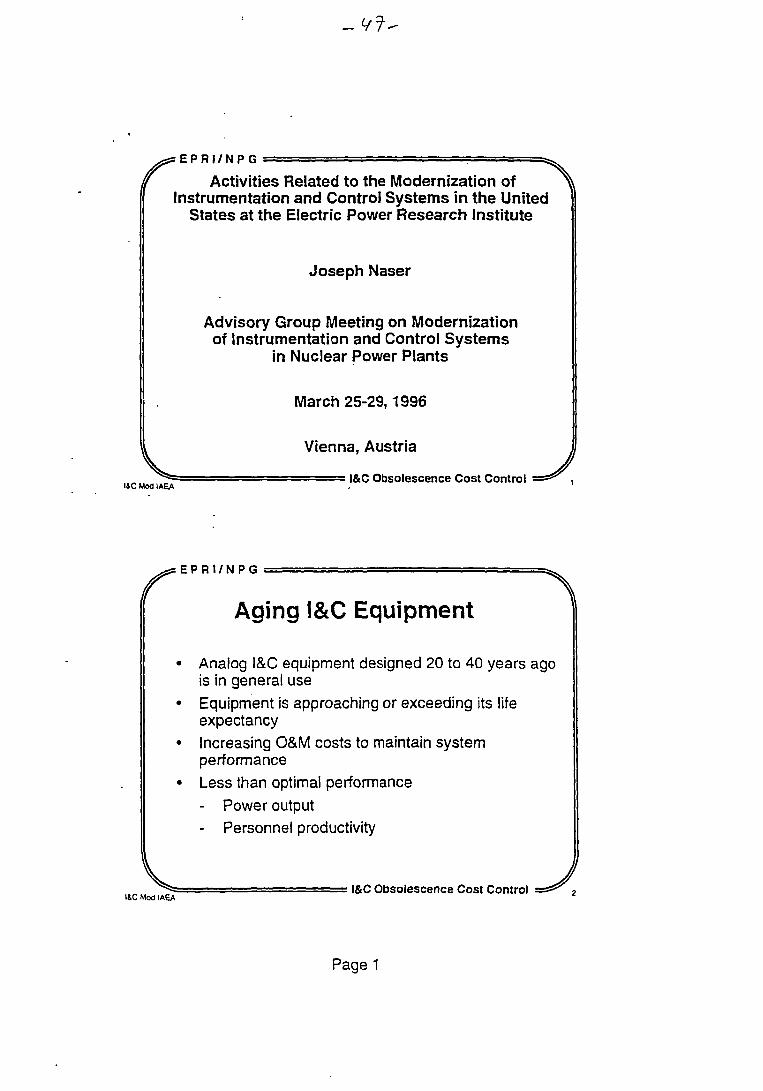
Aging I&C Equipment
• Analog I&C equipment designed 20 to 40 years agois in general use
• Equipment is approaching or exceeding its lifeexpectancy
• Increasing O&M costs to maintain systemperformance
• Less than optimal performance- Power output- Personnel productivity
^ aI4C Moa IAEA
I&C Obsolescence Cost Control
Page 1
Digital Technology
Address equipment obsolescence issuesIncreased functionality for improved performanceState-of-the-practice in other process industriesDemonstrated cost and performanceimprovements
J ^ |&c Obsolescence Cost Control
E P R I / N P G^S tHHI/NHti ^ ^
Digital Technology Supports
• Increased reliability and availability• Reduced O&M costs• Enhanced safety• Increased competitiveness
U i v ^ r = I&C Obsolescence Cost Control =z^\I4C Mod IAEA
Page 2
r US NRC Staff Positions .(Early '90s)
US NRC Staff's concerns with digital technology le.dto:
- Increased scrutiny and requirements with regard toregulatory acceptance of safety-related digitalretrofits
- Publication of a draft Generic Letter on 8/14/92>> "...the installation of digital based safety
systems (1) is an unreviewed safety question,(2) will require a review by the NRC staff, and(3) cannot be performed under the 10 CFR
« 50.59 rule." «
.._ „ ^ f ' "" • = I&C Obsolescence Cost Control =*^ si&C Mod IAEA
E P R I / N P G
Utility Reactions
Regulatory reviews perceived as rapidlyescalating and open-ended with no clearacceptance criteria
Chilling effect on I&C replacement activities- postponement or cancellation of proposed
improvements- implementation of retrofits using old, less
reliable technology
^ ^ s •• I&C Obsolescence Cost Control = s * ^ 6
Page 3
xSJEPRI/NPG -<>.
National Energy Strategy Act(1992)
• Promotes competition between utilities• Generation is very much impacted as electricity
becomes a commodity• Becoming a low-cost producer becomes a
matter of economic survivability- Experience with profit-making process
industries shows that successfulperformance of I&C systems is essential foreconomic survivabiiity
i " " = I&C Obsolescence Cost Control = * ^ 7
E P R I / N P G
Effects on I&C Upgrades
• Resources much tighter
• Shorter payback periods required for new systems• Major emphasis on extending useful life of existing
equipment• Upgrades as last resort with typically "like-for-like"
capabilities• Not taking full advantage of digital technology to
support improved performance and reduced costs
^ ? = I&C Obsolescence Cost Control =s^ „I&C Moa IAEA B
Page 4
.Jl-
> S S E P H I / N P G • •• • - - • •—i=• - jLssa^
EPRI I&C Program
• Working with nuclear power industry to addressI&C issues
• Digital I&C technology• Planning and implementation strategies• Licensing stabilization• Plant demonstrations
^ a = I&C Obsolescence Cost Control =t!^ aISC Mod IAEA '
r E P R I / N P G
ObjectivesAddress obsolescenceReduce O&M costs, improve functionality
Provide strategies for integrating, over aperiod of years, digital systems/subsystems/modules/components into operating plantsPromote stable regulatory approach fordigital technologyProvide capability for implementing digitalI&C systemsReduce costs and shorten the learning curvefor modernizing or maintaining I&C systems
^5= I&C Obsolescence Cost Control = ^ ,0ISC Mod IAEA
Page 5
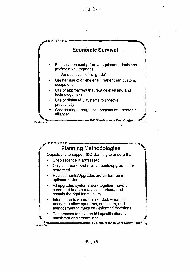
Economic Survival
Emphasis on cost-effective equipment decisions(maintain vs. upgrade)- Various levels of "upgrade"
• Greater use of off-the-shelf, rather than custom,equipment
• Use of approaches that reduce licensing andtechnology risks
• Use of digital I&C systems to improveproductivity
• Cost sharing through joint projects and strategic>\ alliances JIJ^f ' I&C Obsolescence Cost Control =ss^ „
r
I&C Mod IAEA
Planning MethodologiesObjective is to support I&C planning to ensure that:• Obsolescence is addressed• Only cost-beneficial replacements/upgrades are
performed• Replacements/Upgrades are performed in
optimum order• All upgraded systems work together; have a
consistent human-machine interface; andcontain the right functionalityInformation is where it is needed, when it isneeded to allow operators, engineers, andmanagement to make well-informed decisionsThe process to develop bid specifications isconsistent and streamlined
= = = = = = = I&C Obsolescence Cost Control J
Page 6
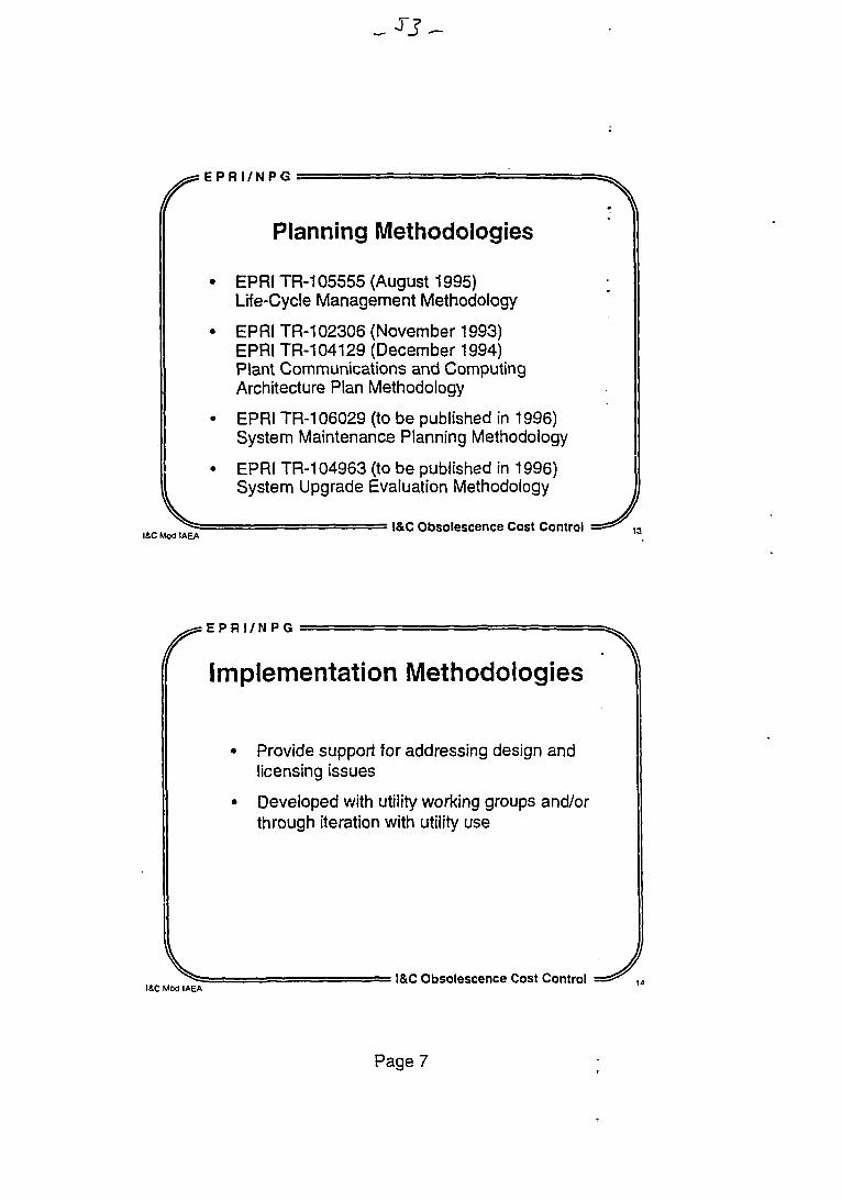
E P R I / N P G^ S S E P R l / N H C a : = =• - - • . a ^
Planning Methodologies
• EPRITR-105555 (August 1995)Life-Cycle Management Methodology
• EPRI TR-102306 (November 1993)EPRI TR-104129 (December 1994)Plant Communications and ComputingArchitecture Plan Methodology
• EPRI TR-106029 (to be published in 1996)System Maintenance Planning Methodology
• EPRI TR-104963 (to be published in 1996)System Upgrade Evaluation Methodology
^ a =' - — = — I&C Obsolescence Cost Control =^^ i3I&C Mod IAEA 1 3
E P R I / N P G-#: t K H I / N K U — • ' - - » ^
Implementation Methodologies
Provide support for addressing design andlicensing issues
Developed with utility working groups and/orthrough iteration with utility use
^ ^ I&C Obsolescence Cost Control = * ^ ..I&C Mod IAEA
Page 7
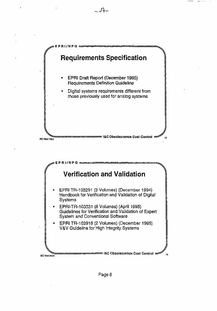
Requirements Specification
EPRI Draft Report (December 1995)Requirements Definition Guideline
Digital systems requirements different fromthose previously used for analog systems
^ = - • = I&C Obsolescence Cost Control = ^ ,5
E P R I / N P G
Verification and Validation
EPRI TR-103291 (3 Volumes) (December 1994)Handbook for Verification and Validation of DigitalSystems
EPRI-TR-103331 (8 Volumes) (April 1995)Guidelines for Verification and Validation of ExpertSystem and Conventional Software
EPRI TR-103916 (2 Volumes) (December 1995)V&V Guideline for High Integrity Systems
^ » I&C Obsolescence Cost Control s * * ^ ,6I&C Mod IAEA 1 5
Page 8
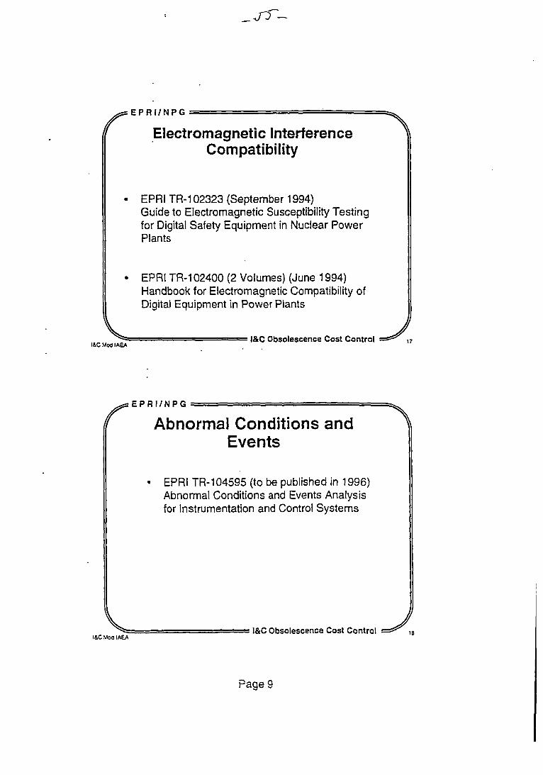
E P R I / N P G
'' Electromagnetic Interference ^Compatibility
EPRI TR-102323 (September 1994)Guide to Electromagnetic Susceptibility Testingfor Digital Safety Equipment in Nuclear PowerPlants
• EPRI TR-102400 (2 Volumes) (June 1994)Handbook for Electromagnetic Compatibility ofDigital Equipment in Power Plants
^ ^ = ? •- • l&C Obsolescence Cost Control =^^ r,I&C Mod IAEA
E P R I / N P G
" Abnormal Conditions andEvents
EPRI TR-104595 (to be published in 1996)Abnormal Conditions and Events Analysisfor Instrumentation and Control Systems
^ » - l&C Obsolescence Cost Control = s ^ iISC Mod IAEA
Page 9
E P R I / N P G
« Use of Commercially AvailableDigital Equipment
EPRI Draft Report (January 1996)Guideline on Evaluation and Acceptance ofCommercial Grade Digital Equipment forNuclear Safety Applications
^ ^ - I&C Obsolescence Cost Control = s ^I&C Mod IAEA 9
E P R I / N P G
Licensing Stabilization
EPRI TR-102348 (December 1993)Guideline on Licensing Digital Upgrades
Generic Letter published on 4/26/95
Renewed interest in digital upgrades
^ > . . I&C Obsolescence Cost Control = ^ ^I&C Mod IAEA
Page 10
^sEPRI /NPG < ^
Objectives of Plant Demonstrations
• Address obsolescence
• Improve functionality, reduce O&M costs
• Integrated implementation of modern technology
• Test bed for generic methodologies, guidelines, andinformation (all four NSSS types)
• Support the development of a stable regulatoryapproach for digital upgrades
• Obtain feedback for needed R&D projects
V JT*= - = I&C Obsolescence Cost Control s * * ^ ,
y s E P R I / N P G • ^
I&C Plant Demonstration Participants
Plants:• Browns Ferry Unit 2• Calvert Cliffs Units 1 & 2• Prairie Island Units 1 & 2• ANO Units 1 & 2• FortCalhoun• Chinshan
^ = = = I&C Obsolescence Cost Control =*^ &I&C Mod IAEA
Page 11
« Some Lessons Learned *1. Importance of baseline interviews including plant
personnel2. Structured upgrade planning
• can postpone need for upgrade capital• benefits from supplier participation
3. Planning and implementation methodologies• can be generic• improve with trial use
4. Need to coordinate I&C upgrade planning with• plant strategic plan
„ • site computer network ,
^ = I&C Obsolescence Cost Control = s * ^ 2
r Some Lessons Learned(cont'd)
5. Strategic upgrade planning• must accommodate known short-term upgrades• identifies some immediate needs• causes focus on maintenance effectiveness
6. Importance of network architecture planning7. O&M cost concern is a major factor in I&C
upgrades8. Licensing cost uncertainty must be eliminated9. Standardization and use of commercial grade
equipment are needed for cost effectiveness« 10. More later - stay tuned ,
^ ^ I&C Obsolescence Cost Control = s ^ 24
Page 12
E P R I / N P G
f Strategic Alliances
• Need for various organizations to work togetherto:- Share resources and benefits- Reduce first-of-a-kind development,
implementation, and licensing costs andrisks
- Develop standardized approaches- Reduce duplication of effort- Increase new systems available for use
^ ^ •• •• I&C Obsolescence Cost Control = ^ , ,ISC Moa IAEA . Z 5
E P R I / N P G^ E P R I / N P U = = ^
Joint Industry/DOE I&C Program
Catalyst to resolve industry's major I&CproblemsIndustry led and driven programStrategic alliances to reduce cost and licensingrisks of first implementationsInternational programMore cost competitive generation facilitiesIncreased competitiveness for suppliers
^ » I&C Obsolescence Cost Control = ^ ,BI&C Mod IAEA Z b
Page 13
EPRI /NPG
V
Initial Projects
Application Specific Integrated Circuits forSafety and Control SystemsCommercially Available ProgrammableLogic Controllers for Safety and ControlSystems
Dynamic Safety System Technology forReactor Protection Systems
ISC Mod IAEA' I&C Obsolescence Cost Control
Page 14
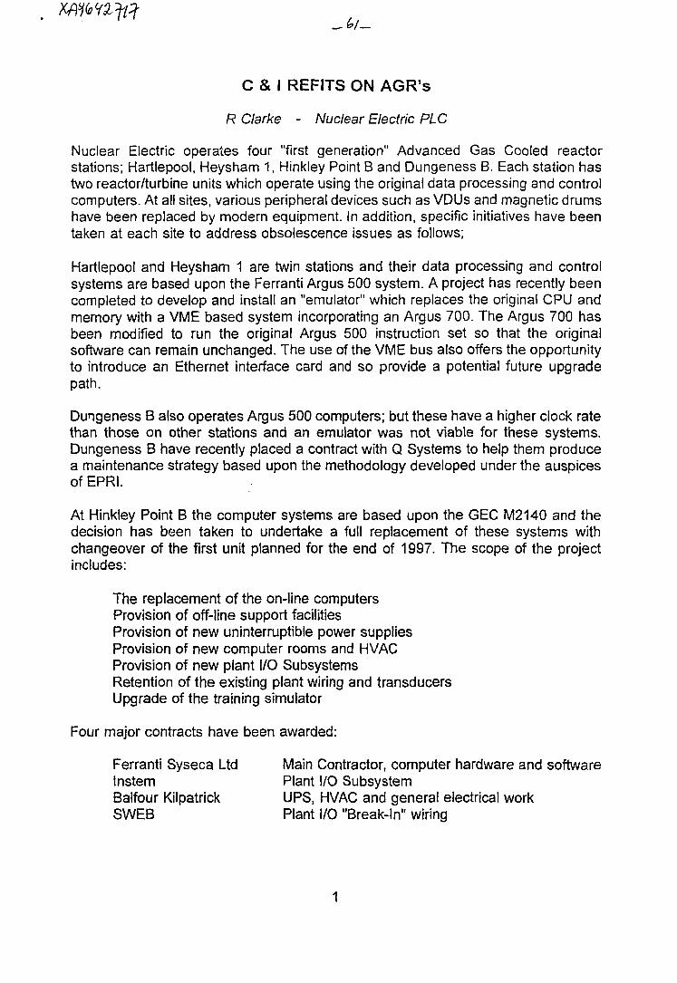
C & I REFITS ON AGR's
R Clarke - Nuclear Electric PLC
Nuclear Electric operates four "first generation" Advanced Gas Cooled reactorstations; Hartlepool, Heysham 1, Hinkley Point B and Dungeness B. Each station hastwo reactor/turbine units which operate using the original data processing and controlcomputers. At all sites, various peripheral devices such as VDUs and magnetic drumshave been replaced by modern equipment. In addition, specific initiatives have beentaken at each site to address obsolescence issues as follows;
Hartlepool and Heysham 1 are twin stations and their data processing and controlsystems are based upon the Ferranti Argus 500 system. A project has recently beencompleted to develop and install an "emulator" which replaces the original CPU andmemory with a VME based system incorporating an Argus 700. The Argus 700 hasbeen modified to run the original Argus 500 instruction set so that the originalsoftware can remain unchanged. The use of the VME bus also offers the opportunityto introduce an Ethernet interface card and so provide a potential future upgradepath.
Dungeness B also operates Argus 500 computers; but these have a higher clock ratethan those on other stations and an emulator was not viable for these systems.Dungeness B have recently placed a contract with Q Systems to help them producea maintenance strategy based upon the methodology developed under the auspicesof EPRI.
At Hinkley Point B the computer systems are based upon the GEC M2140 and thedecision has been taken to undertake a full replacement of these systems withchangeover of the first unit planned for the end of 1997. The scope of the projectincludes:
The replacement of the on-line computersProvision of off-line support facilitiesProvision of new uninterruptible power suppliesProvision of new computer rooms and HVACProvision of new plant I/O SubsystemsRetention of the existing plant wiring and transducersUpgrade of the training simulator
Four major contracts have been awarded:
Ferranti Syseca Ltd Main Contractor, computer hardware and softwareInstem Plant I/O SubsystemBalfour Kilpatrick UPS, HVAC and general electrical workSWEB Plant I/O "Break-In" wiring
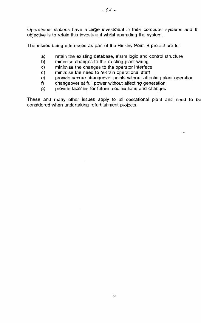
Operational stations have a large investment in their computer systems and thobjective is to retain this investment whilst upgrading the system.
The issues being addressed as part of the Hinkley Point B project are to:-
a) retain the existing database, alarm logic and control structureb) minimise changes to the existing plant wiringc) minimise the changes to the operator interfaced) minimise the need to re-train operational staffe) provide secure changeover points without affecting plant operationf) changeover at full power without affecting generationg) provide facilities for future modifications and changes
These and many other issues apply to all operational plant and need to beconsidered when undertaking refurbishment projects.
Modernization of the Ukrainian VVER-1000NPP Instrumentation and Control Systems
Mikhail Yastrebenetsky,Dr. of Sc, Prof,
Head of I&C DepartmentState Scientific Technical Centerof Nuclear and Radiation Safety,Kharkov, Ukraine, 310002,Artema str. 17Tel/fax (038-0572)-47-17-00.
IAEA Advisory Group Meeting on "Modernization of Instru-mentation and Control Systems in Nuclear Power Plants".
Vienna, 25-29 March 1996.
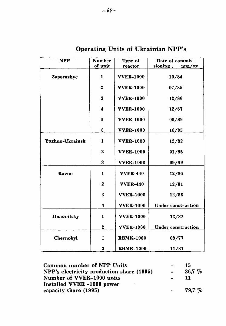
Operating Units of Ukrainian NPP's
NPP
Zaporozhye
Yuzhno-Ukrainsk
Rovno
Hmelnitsky
Chernobyl
Numberof unit
1
2
3
4
5
6
1
2
3
1
2
3
4
1
2
1
3
Type ofreactor
VVER-1000
VVER-1000
VVER-1000
VVER-1000
VVER-1000
VVER-1000
VVER-1000
VVER-1000
VVER-1000
VVER-440
VVER-440
VVER-1000
VVER-1000
VVER-1000
VVER-1000
RBMK-1000
RBMK-1000
Date of commis-sioning , mm/yy
10/84
07/85
12/86
12/87
08/89
10/95
12/82
01/85
09/89
12/80
12/81
12/86
Under construction
12/87
Under construction
09/77
11/81
Common number of NPP UnitsNPP's electricity production share (1995)Number of VVER-1000 unitsInstalled VVER -1000 powercapacity share (1995)
1536,7 %11
79,7 %
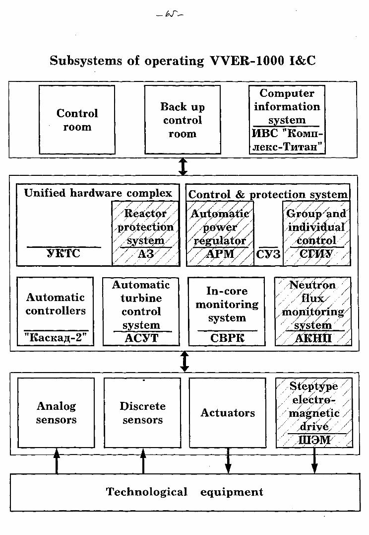
Subsystems of operating VVER-1000 I&C
Controlroom
Back upcontrolroom
Computerinformation
systemMBC "KOMH-
IUnified hardware complex
yKTC
/ ./ / ./ / /"Reactor
• • • • • - • ' . . - • • • • • , • • • • . - - • • /
protection/ / / . • • • • / . •'
••••"•',--£ys.te.in/. -•y/£&///
Automaticcontrollers
"KacKafl-2"
Control & protection system
CY3
AutomaticturbinecontrolsystemACYT
In-coremonitoring
system
CBPK
••Ne.utrbn •
monitbring
Analogsensors
Discretesensors
IActuators
I
Stept^peelectro-
Technological equipment
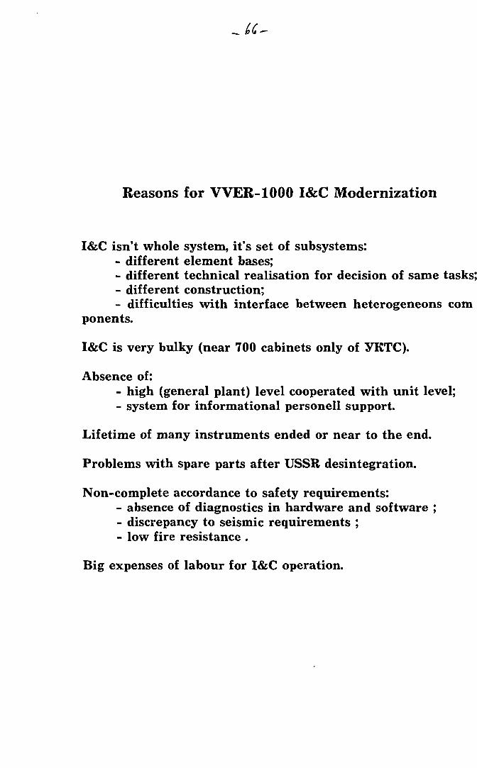
Reasons for VVER-1000 I&C Modernization
I&C isn't whole system, it's set of subsystems:- different element bases;- different technical realisation for decision of same tasks;- different construction;- difficulties with interface between heterogeneons com
ponents.
I&C is very bulky (near 700 cabinets only of yKTC).
Absence of:- high (general plant) level cooperated with unit level;
- system for informational personell support.
Lifetime of many instruments ended or near to the end.
Problems with spare parts after USSR desintegration.
Non-complete accordance to safety requirements:- absence of diagnostics in hardware and software ;- discrepancy to seismic requirements ;- low fire resistance .
Big expenses of labour for I&C operation.
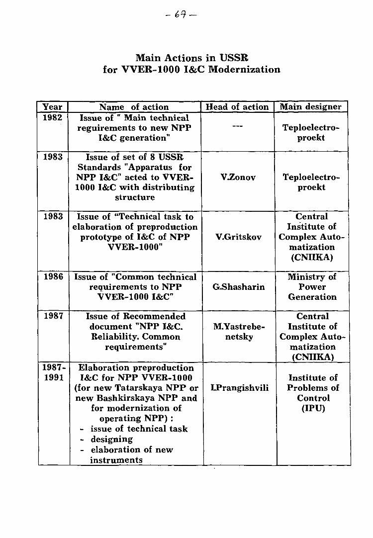
Main Actions in USSRfor VVER-1000 I&C Modernization
Year1982
1983
1983
1986
1987
1987-1991
Name of actionIssue of " Main technical
reguirements to new NPPI&C generation"
Issue of set of 8 USSRStandards "Apparatus forNPP I&C acted to VVER-1000 I&C with distributing
structure
Issue of "Technical task toelaboration of preproduction
prototype of I&C of NPPVVER-1000"
Issue of "Common technicalrequirements to NPP
VVER-1000 I&C"
Issue of Recommendeddocument "NPP I&C.Reliability. Common
requirements"
Elaboration preproductionI&C for NPP VVER-1000
(for new Tatarskaya NPP ornew Bashkirskaya NPP and
for modernization ofoperating NPP) :
- issue of technical task- designing- elaboration of new
instruments
Head of action
—
V.Zonov
V.Gritskov
G.Shasharin
M.Yastrebe-netsky
LPrangishvili
Main designer
Teploelectro-proekt
Teploelectro-proekt
CentralInstitute of
Complex Auto-matization(CNIIKA)
Ministry ofPower
Generation
CentralInstitute of
Complex Auto-matization(CNIIKA)
Institute ofProblems of
Control(IPU)
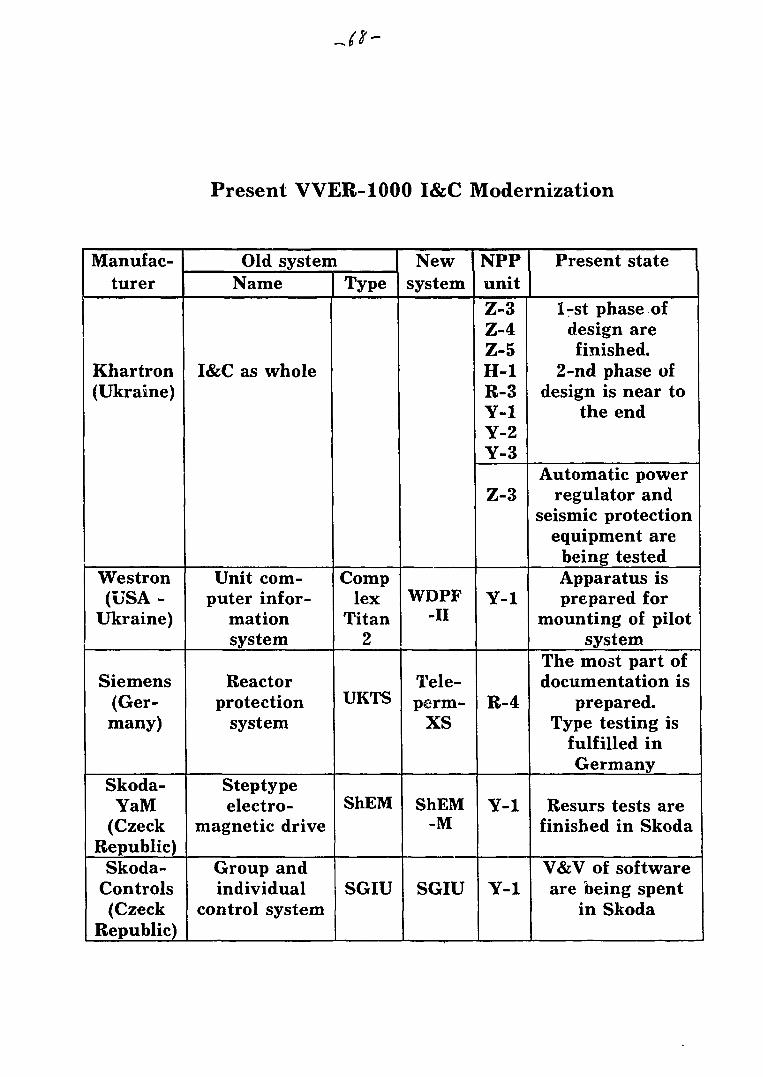
Present VVER-1000 I&C Modernization
Manufac-turer
Khartron(Ukraine)
Westron(USA -
Ukraine)
Siemens(Ger-many)
Skoda-YaM
(CzeckRepublic)
Skoda-Controls(Czeck
Republic)
Old systemName
I&C as whole
Unit com-puter infor-
mationsystem
Reactorprotection
system
Steptypeelectro-
magnetic drive
Group andindividual
control system
Type
Complex
Titan2
UKTS
ShEM
SGIU
Newsystem
WDPF-II
Tele-perm-
XS
ShEM-M
SGIU
NPPunitZ-3Z-4Z-5H-1R-3Y-1Y-2Y-3
Z-3
Y-1
R-4
Y-1
Y-1
Present state
1-st phase ofdesign arefinished.
2-nd phase ofdesign is near to
the end
Automatic powerregulator and
seismic protectionequipment are
being testedApparatus isprepared for
mounting of pilotsystem
The most part ofdocumentation is
prepared.Type testing is
fulfilled inGermany
Resurs tests arefinished in Skoda
V&V of softwareare being spent
in Skoda
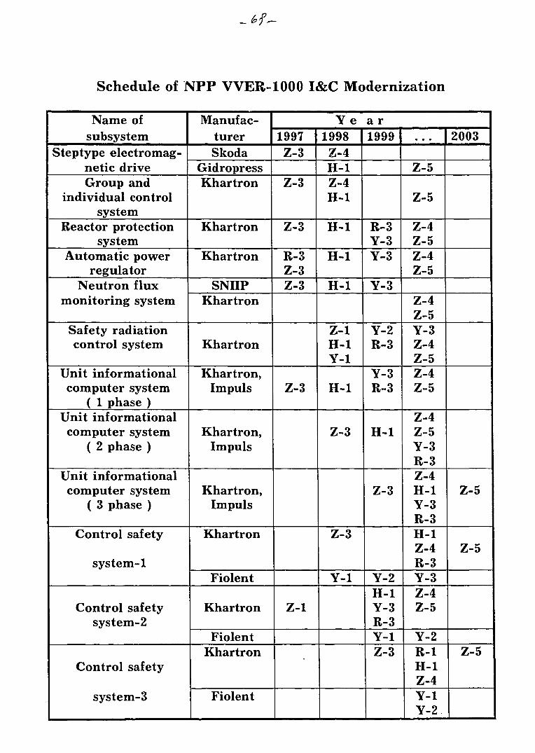
Schedule of NPP VVER-1000 I&C Modernization
Name ofsubsystem
Steptype electromag-netic driveGroup and
individual controlsystem
Reactor protectionsystem
Automatic powerregulator
Neutron fluxmonitoring system
Safety radiationcontrol system
Unit informationalcomputer system
( 1 phase )Unit informationalcomputer system
( 2 phase )
Unit informationalcomputer system
( 3 phase )
Control safety
system-1
Control safetysystem-2
Control safety
system-3
Manufac-turerSkoda
GidropressKhartron
Khartron
Khartron
SNIIPKhartron
Khartron
Khartron,Impuls
Khartron,Impuls
Khartron,Impuls
Khartron
Fiolent
Khartron
FiolentKhartron
Fiolent
1997Z-3
Z-3
Z-3
R-3Z-3Z-3
Z-3
Z-1
Ye1998Z-4H-1Z-4H-1
H-1
H-1
H-1
Z-1H-1Y-1
H-1
Z-3
Z-3
Y-1
a r1999
R-3Y-3Y-3
Y-3
Y-2R-3
Y-3R-3
H-1
Z-3
Y-2H-1Y-3R-3Y-1Z-3
•. •
Z-5
Z-5
Z-4Z-5Z-4Z-5
Z-4Z-5Y-3Z-4Z-5Z-4Z-5
Z-4Z-5Y-3R-3Z-4H-1Y-3R-3H-1Z-4R-3Y-3Z-4Z-5
Y-2R-1H-1Z-4Y-1Y-2
2003
Z-5
Z-5
Z-5
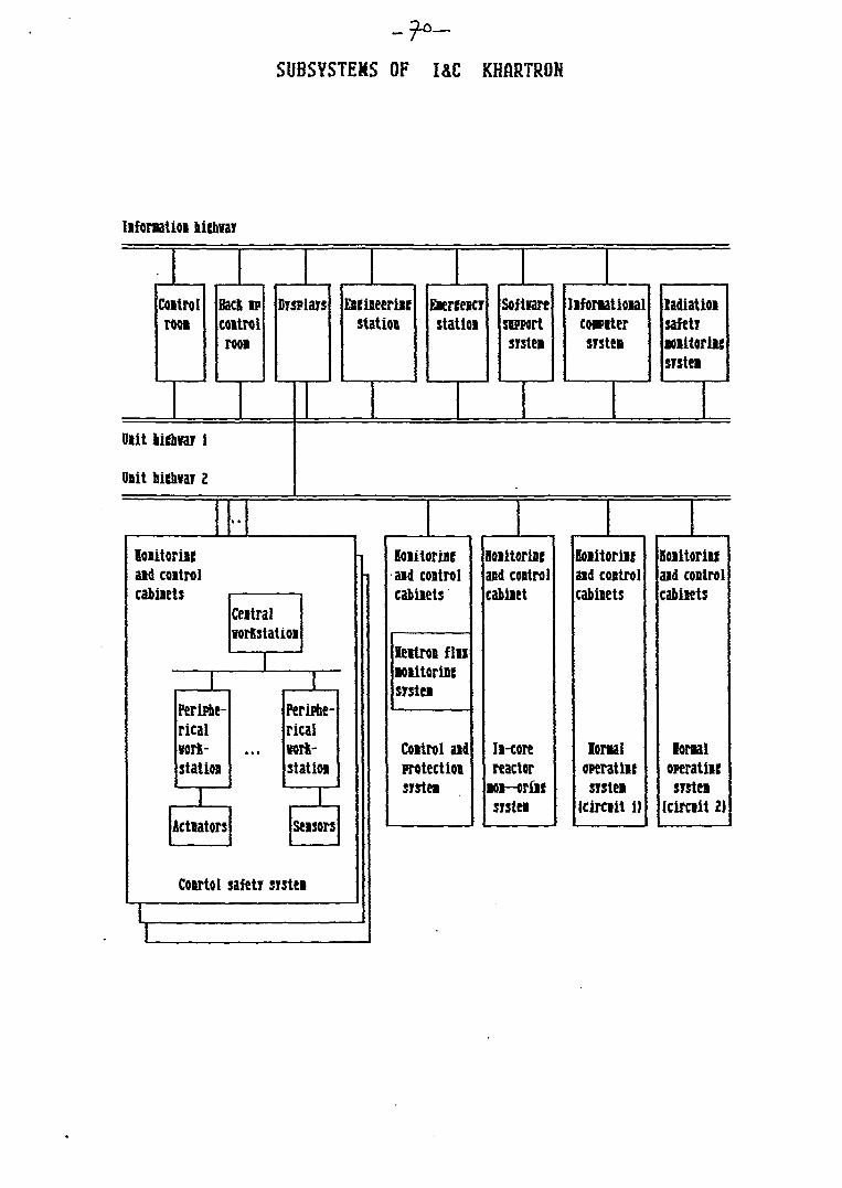
SUBSYSTEMS OF I&C KHARTROH
lifonatioi biebvar
Coitrolrow
Back IFcoitrolroot
Displays Eseiieeriiestatin
aeiteicrstatioi
Softiareswwrtsrstei
liforiatioialc«ntersrstei
ladiatioisafetrMBitoriusrstei
Oiit
Unit hichvar 2
Koiitoriieaid coitrolcabiiets
Ccitralvorkstatioi
1PerMe-ricalwrt-statioa
1
• • •
Ferifte-rical»rt-statioi
1Acttators
1Seisors
CoBrtol safetr srstei
Boiitorincaid costro!cabiiets
leitroi finMiitorinesrstei
Coitrol aidirotectioisrstei
loiitoriieand coitrolcabiiet
Ii-corereactor
Mi-oriiesrstei
Buitoriieaid controlcabiiets
Ioraaloperatiiesrstei
(circiit i)
Hoiitoriieaid controlcabiiets
Ioraaioperatiicsrstei
(circiit 2)
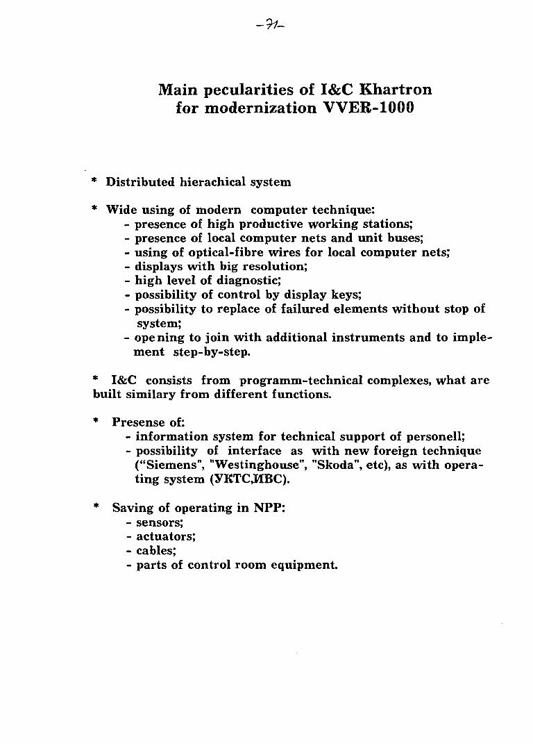
Main peculiarities of I&C Khartronfor modernization VVER-1000
* Distributed hierachical system
* Wide using of modern computer technique:- presence of high productive working stations;- presence of local computer nets and unit buses;- using of optical-fibre wires for local computer nets;- displays with big resolution;- high level of diagnostic;- possibility of control by display keys;- possibility to replace of failured elements without stop of
system;- opening to join with additional instruments and to imple
ment step-by-step.
* I&C consists from programm-technical complexes, what arebuilt similary from different functions.
* Presense of:- information system for technical support of personell;- possibility of interface as with new foreign technique
("Siemens", "Westinghouse", "Skoda", etc), as with opera-ting system (YKTCJUBC).
* Saving of operating in NPP:- sensors;- actuators;- cables;- parts of control room equipment.
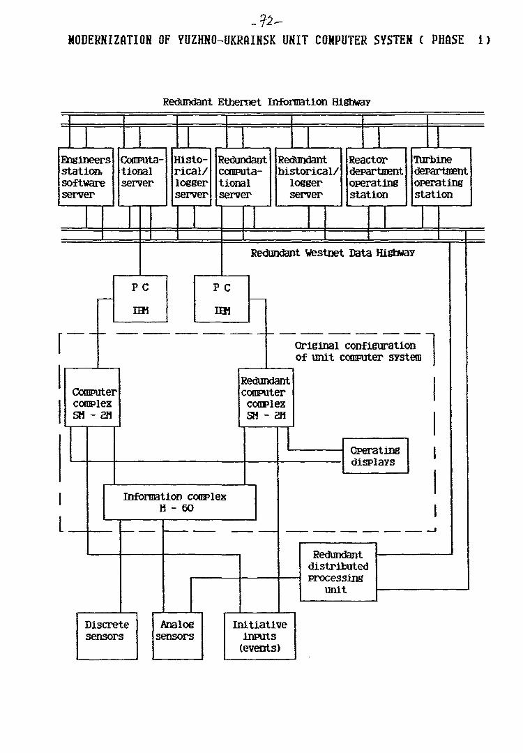
MODERNIZATION OF YUZHNO-UKRAINSK UNIT COMPUTER SYSTEM ( PHASE i)
Redundant Ethernet Information Highway
Engineersstation,softwareserver
Computa-tionalserver
Histo-rical/loggerserver
Redundantcomputa-tionalserver
Redundanthistorical/
loggerserver
Reactordepartmentoperatingstation
Turbinedepartmentoperatingstation
Redundant Westnet Data Highway
Original configurationof unit computer system1
ComputercomplexSH - 2H
RedundantcomputercomplexSH - 2H
Information complexH - 60
Discretesensors
Analogsensors
Operatingdisplays
Redundantdistributedprocessing
unit
Initiativeinputs(events)
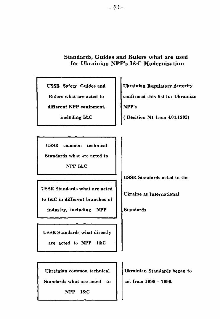
Standards, Guides and Rulers what are usedfor Ukrainian NPP's I&C Modernization
USSR Safety Guides and
Rulers what are acted to
different NPP equipment,
including I&C
USSR common technical
Standards what are acted to
NPP I&C
USSR Standards what are acted
to I&C in different branches of
industry, including NPP
USSR Standards what directly
are acted to NPP I&C
Ukrainian common technical
Standards what are acted to
NPP I&C
Ukrainian Regulatory Autority
confirmed this list for Ukrainian
NPP's
( Decision Nl from 4.01.1992)
USSR Standards acted in the
Ukraine as International
Standards
Ukrainian Standards began to
act from 1995 - 1996.
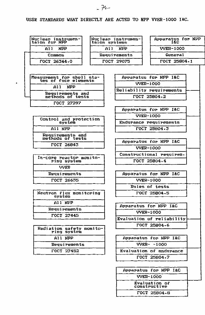
USSR STANDARDS WHAT DIRECTLY ARE ACTED TO NPP W E R - 1 0 0 0 I&C.
Nuclear instrumen-tal on for NPP
All NPP
Common
TOCT 26344-0
Nuclear instrumen-tal on systems
Al1 NPP
Requ i reroents
TOCT 29075
Measurment for shel1 sta-tes of fuce element5
All NPPRequi rements andmethods of tests
rOCT 27297
Control and protectionsystem
All NPPRequirements andmethods of tests
TOCT 26843
In-core reactor monito-ring system
WERRequ i rement s
TOCT 26635
Neutron flux monitoringsystem
All NPP
Bequi rements
TOCT 27445
Radiation safety monito-ring system
All NPP
Requirements
TOCT 27452
Apparatus for NPPI&C
WER-1000General
TOCT 25804.1
Apparatus for NPP I&CWER-1000
Reliability requirements
TOCT 25804.2
Apparatus for NPP I&CWER-1000
Endurance requirements
TOCT 25B04-3
Apparatus for NPP I&CWER-1000
Constructional requirem.
TOCT 25804.4
Apparatus for NPP I&CWER-1000
Rules of tests
TOCT 25804-5
Apparatus for NPP I&CWER-1000
Evaluation of reliability
TOCT 25804-6
Apparatus for NPP I&C
WER- -1000
Evaluation of endurance
TOCT 25804-7
Apparatus f or NPP I&CWER-1000Evaluation ofconstructive
TOCT 25804-8
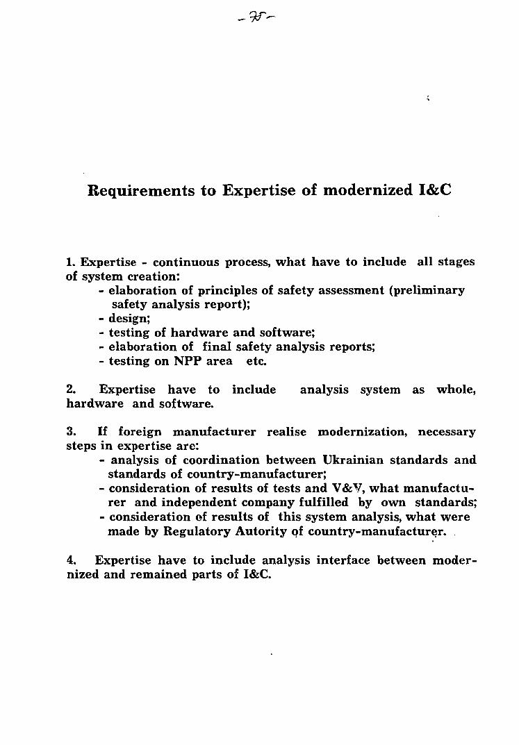
Requirements to Expertise of modernized I&C
1. Expertise - continuous process, what have to include all stagesof system creation:
- elaboration of principles of safety assessment (preliminarysafety analysis report);
- design;- testing of hardware and software;- elaboration of final safety analysis reports;- testing on NPP area etc
2. Expertise have to include analysis system as whole,hardware and software.
3. If foreign manufacturer realise modernization, necessarysteps in expertise are:
- analysis of coordination between Ukrainian standards andstandards of country-manufacturer;
- consideration of results of tests and V&V, what manufactu-rer and independent company fulfilled by own standards;
- consideration of results of this system analysis, what weremade by Regulatory Autority of country-manufacturer.
4. Expertise have to include analysis interface between moder-nized and remained parts of I&C.
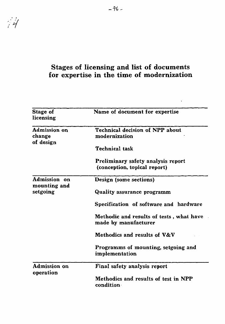
Stages of licensing and list of documentsfor expertise in the time of modernization
Stage oflicensing
Name of document for expertise
Admission onchangeof design
Technical decision of NPP aboutmodernization
Technical task
Preliminary safety analysis report(conception, topical report)
Admission onmounting andsetgoing
Design (some sections)
Quality assurance programm
Specification of software and hardware
Methodic and results of tests , what havemade by manufacturer
Methodics and results of V&V
Programms of mounting, setgoing andimplementation
Admission onoperation
Final safety analysis report
Methodics and results of test in NPPcondition
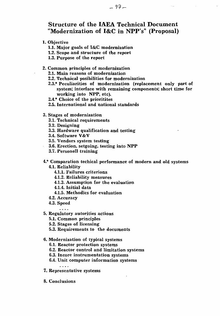
Structure of the IAEA Technical Document"Modernization of I&C in NPP's" (Proposal)
1. Objective1.1. Major goals of I&C modernization1.2. Scope and structure of the report1.3. Purpose of the report
2. Common principles of modernization2.1. Main reasons of modernization2.2. Technical posibilities for modernization2.3.* Peculiarities of modernization (replacement only part of
system; interface with remaining components; short time forworking into NPP, etc).
2.4.* Choice of the prioritites2.5. International and national standards
3. Stages of modernization3.1. Technical requirements3.2. Designing3.3. Hardware qualification and testing3.4. Software V&V3.5. Vendors system testing3.6. Erection, setgoing, testing into NPP3.7. Personell training
4.* Comparation techical performance of modern and old systems4.1. Reliability
4.1.1. Failures criterions4.1.2. Reliability measures4.1.3. Assumption for the evaluation4.1.4. Initial data4.1.5. Methodics for evaluation
4.2. Accuracy4.3. Speed
5. Regulatory autorities actions5.1. Common principles5.2. Stages of licensing5.3. Requirements to the documents
6. Modernization of typical systems6.1. Reactor protection systems6.2. Reactor control and limitation systems6.3. Incore instrumentation systems6.4. Unit computer information systems
7. Representative systems
8. Conclusions

-n-
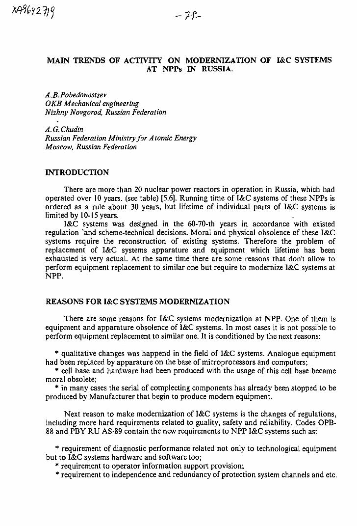
MAIN TRENDS OF ACTIVITY ON MODERNIZATION OF I&C SYSTEMSAT NPPs IN RUSSIA.
A. B. PobedonostsevOKB Mechanical engineeringNizhny Novgorod, Russian Federation
A.G.ChudinRussian Federation Ministry for Atomic EnergyMoscow, Russian Federation
INTRODUCTION
There are more than 20 nuclear power reactors in operation in Russia, which hadoperated over 10 years, (see table) [5.6]. Running time of I&C systems of these NPPs isordered as a rule about 30 years, but lifetime of individual parts of I&C systems islimited by 10-15 years.
I&C systems was designed in the 60-70-th years in accordance with existedregulation 'and scheme-technical decisions. Moral and physical obsolence of these I&Csystems require the reconstruction of existing systems. Therefore the problem ofreplacement of I&C systems apparature and equipment which lifetime has beenexhausted is very actual. At the same time there are some reasons that don't allow toperform equipment replacement to similar one but require to modernize I&C systems atNPP.
REASONS FOR I&C SYSTEMS MODERNIZATION
There are some reasons for I&C systems modernization at NPP. One of them isequipment and apparature obsolence of I&C systems. In most cases it is not possible toperform equipment replacement to similar one. It is conditioned by the next reasons:
* qualitative changes was happend in the field of I&C systems. Analogue equipmenthad been replaced by apparature on the base of microprocessors and computers;
* cell base and hardware had been produced with the usage of this cell base becamemoral obsolete;
* in many cases the serial of complecting components has already been stopped to beproduced by Manufacturer that begin to produce modern equipment.
Next reason to make modernization of I&C systems is the changes of regulations,including more hard requirements related to guality, safety and reliability. Codes OPB-88 and PBY RU AS-89 contain the new requirements to NPP I&C systems such as:
* requirement of diagnostic performance related not only to technological equipmentbut to I&C systems hardware and software too;
* requirement to operator information support provision;* requirement to independence and redundancy of protection system channels and etc.
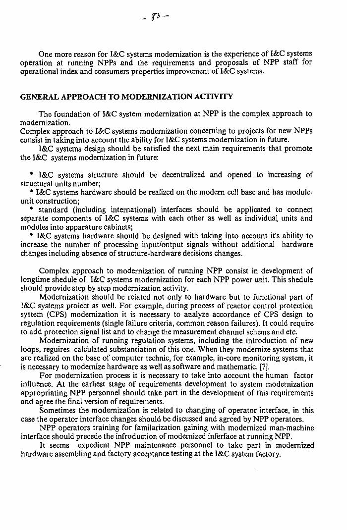
One more reason for I&C systems modernization is the experience of I&C systemsoperation at running NPPs and the requirements and proposals of NPP staff foroperational index and consumers properties improvement of I&C systems.
GENERAL APPROACH TO MODERNIZATION ACTIVITY
The foundation of I&C system modernization at NPP is the complex approach tomodernization.Complex approach to I&C systems modernization concerning to projects for new NPPsconsist in taking into account the ability for I&C systems modernization in future.
I&C systems design should be satisfied the next main requirements that promotethe I&C systems modernization in future:
* I&C systems structure should be decentralized and opened to increasing ofstructural units number;
* I&C systems hardware should be realized on the modern cell base and has module-unit construction;
* standard (including international) interfaces should be applicated to connectseparate components of I&C systems with each other as well as individual units andmodules into apparature cabinets;
* I&C systems hardware should be designed with taking into account it's ability toincrease the number of processing input/ontput signals without additional hardwarechanges including absence of structure-hardware decisions changes.
Complex approach to modernization of running NPP consist in development oflongtime shedule of I&C systems modernization for each NPP power unit. This sheduleshould provide step by step modernization activity.
Modernization should be related not only to hardware but to functional part ofI&C systems proiect as well. For example, during process of reactor control protectionsystem (CPS) modernization it is necessary to analyze accordance of CPS design toregulation requirements (single failure criteria, common reason failures). It could requireto add protection signal list and to change the measurement channel schems and etc.
Modernization of running regulation systems, including the introduction of newloops, reguires calculated substantiation of this one. When they modernize systems thatare realized on the base of computer technic, for example, in-core monitoring system, itis necessary to modernize hardware as well as software and mathematic. [7].
For modernization process it is necessary to take into account the human factorinfluence. At the earliest stage of requirements development to system modernizationappropriating NPP personnel should take part in the development of this requirementsand agree the final version of requirements.
Sometimes the modernization is related to changing of operator interface, in thiscase the operator interface changes should be discussed and agreed by NPP operators.
NPP operators training for familarization gaining with modernized man-machineinterface should precede the infroduction of modernized inferface at running NPP.
It seems expedient NPP maintenance personnel to take part in modernizedhardware assembling and factory acceptance testing at the I&C system factory.
- £7-
CURRENT PRACTICE OF OPERATING NPP MODERNIZATION
Modernization of I&C systems at operating NPP are performed in Russia now.Modernization usually consist in individual system hardware replacement or
addition to existing I&C systems project of new additional systems. Such activity is notintended for largescale modernization and lead in the first turn to autority requirementsaccordance and safety and effectivity improvement of operation.
Great efforts are undertaken in the field of operator support system (OSS)development and implementation.
The working group composed by the specialists of several russian organizations onthe request of Concern Rosenergoatom developed the concept of an information supportsystem for operational personnel of operating NPP.
The main objective of an information support system is to help an operator in themain control room to evaluate a safety status of power unit.
The first priority functions of operator support that intended for theimplemantation at the running NNPs are a critical safety functions display, intellectualannunciation system, early fault detection and diagnosis. Information support system ofoperator can be implemented as a separate computer module integrated in operatingprocess control system of a power unit. The work of the implememtation of aninformation support system is being carried out in the framework of modernization ofoperating process control system. It is supposed to introduce OSS at running NPP bysereral stages, step-by-step. The implementation of OSS should be performed on thebasis of the analysis for every power unit of available information system, personnelactivity and determination of a set of the OSS functions to be developed, of thesefunctions realization methods and their integration ways with existing runninginformation system [1].
Development of OSS are fulfilled by many russian organizations. Suchdevelopments are performed not only for I&C systems modernization but for new NPPprojects as well. For example, the OSS design for Voronezh nuclear heating plant aredeveloped by OKB Mechanical engineering; there is operating model of OSS that isrealized on the base of PC. Such experience of russian organizations on OSSdevelopment creates the foundation for information systems modernization of operatingNPPs.
One of the directions in the field of OSS is the development of Safety ParametersDisplay Systems (SPDS).
The pilot program for SPDS design and implementation at Balakovo NPP (PWR)and Lenningrad NPP (RBMK) are developed in Russia.
The russian organizations and american firm (Westinghouse) take part in SPDSdevelopment in the framework of this program.
Westinghouse-firm has successful experience in the area of development andimplementation of SPDS systems in USA [2].
Activity for diagnostic system development and implementation for NPPtechnological equipment and processes diagnosis are performed in Russia.
Diagnostic systems are realized as hardware-software sets for vibrationmonitoring, equipment lifetime assessment, leakage montoring, loose parts monitoring.
These systems are implemented as local autonomous information systems. Data oftechnologial process are received by diagnostic system from existing information systemand it's own additional sensors.
The diagnostics systems begin to be implemented at NPP. At the beginning of 1993the expert on-line diagnosis system was put into trival operation at Leningrad - 1 NPP.At present this system is used to diagnose 11 technological subsystems. The diagnosissystem provide:
* to monitor the process state of the diagnosed technological subsystems at themacrolevel (healthy-unhealthy);
* to determine the type of malfunction, its cause and location, if there is any trouble;* to represent on the display screen digital and graphic data on any subsystem being
diagnosed;* to record the diagnosis result in the archive on the user request.
The foundation of this diagnosis system is the software program block that isrunning in the operating system MS DOS for IBM PC and compatible computers [3].
Moscow science and research centre SNIIP developed new modern hardwarecomplex for VVER-440 reactor control and protection system (AKNP-7, AZTP, ALOS,AOP and AKNP-7-02 for VVER-1000) that is conformed to modern normativerequirements and is performed neutron flux monitoring, logistic process of data andprotection signal formation, representation and recording of information. This moderncontrol and protection system hardware are installed and operate at South-Ukraine NPPand Rovno NPP in the Ukraine as well as at Kola NPP-1.2 and Novo-Voronezh NPP inRussia.
Such activity related to reactor control & protection system (CPS) modernizationnad been performed for the 3th power unit of Beloyarskay NPP (fast type reactor) byNPO, "Avtomatika" (Omsk, Russia).
Equipment for control rods motors control concerning VVER-type operatingreactors are modernizing as well.
Modernization generally is performed at the level of individual units and modulesand is related to cell bas: replacement and sometimes scheme decisions improvements[7]-
Russian organizations take part in CPS systems' modernization for Ukraine NPPsas well. It is supposed for South-Ukraine NPP several CPS subsystem (ROM, ARM,control of control rods motors) to realize on the base of microprocessers.
The putting of these systems into operation should be possible after the softwarelicencing as well as hardware [7].
It is necessary to vote that the level of production technology of reactor control &protection systems in Russia does not always correspond to the level of the systemdevelopment. This one is the main reason why foreing firms co-operate in a number ofCPS designs.
The successful experience of russian and french firm collaboration has been alreadypresented while development of functional part of CPS reconstruction project for KolaNPP-3 and 4 [4].
Collaboration of russian organizations with foreing firms has some features.Project of I&C systems modernization always is designed by russian organization that isspecialized in the field of I&C systems for NPPs development. Russian designorganization defines the modernization strategy, key technical decisions, performessafety provision substantiation and is responsible for correctness of design. Suchapproach is conditioned by russian organizations large experience and knowledge in thefield of NPP technological processes, russian standards and regulations related to I&Csystems for NPPs, current practice of I&C systems development and operation in Russia.Collaboration of russian organizations with foreing firms consist in combineddevelopment of metodology for individual tasks solving (for example, SPDS). Russianorganizations perform in this case the analisys of methods for problem solving and theiradaptation for russian conditions. Sometimes it is supposed to use foreing hardware forI&C systems modernization. In this case it is expedient to involve foreing firms that havethe experience in such technic application in th? works on modernization. Collaboration
provides to chouse the optimal technical decisions and to eliminate design errors relatedto foreing hardware application.
CONCLUSION
* It is supposed to modernize I&C systems of NPP on the base of complex approach.The longtime shedule of I&C systems modernization for each NPP power unit should bedeveloped. Such shedule should provide stage-by-stage modernization.
Modernization should be related not only to hardware but to functional part ofI&C system project as well.
* Current practice of information system modernization usually consist in adding toexisting I&C systems new systems (OSS, SPDS, diagnostic systems) that are realized aslocal systems connected with existing I&C systems for process information acquisition .It is supposed to introduce new systems into operation gradually and increase theirfunctionability step-by-step.
* Control system modernization is performed in the first turn for safety importantsystems including reactor control and protection systems.
* Project of I&C systems modernization for russian NPPs is developed by russianorganizations that are specialized in the field of I&C systems for NPPs development. Themain reason for such approach is conditioned by next circumstance. Russian designorganizations have large experience and knowledges in the field of NPP1 technologicalprocesses, russian standards and regulations related to I&C systems for NPPs, currentpractice of I&C systems development and operation in Russia. When it is expedient fromeconomical and technical point of view foreing firms together with russian organizationstake part in the works on I&C systems modernization.
REFERENCES
1. V.G.Dounaev, V.V.Golovanov. The concept of an information support system for operationalpersonnel of operating nuclear power plants. Operator support systems in nuclear power plants. IAEA,Vienna, 1994, IAEA-TECDOC-762.
2. J.Boucau, S.Smirnov, A.I.Gorelov and all. The SPLS as a tool to improve post-accident strategyon VVER and RBMK reactors. Operator support systems in nuclear power plants. IAEA, Vienna, 1994,IAEA-TECDOC-762.
3. E.O.Adamov, O.N.Glazov, A.P.Eperin, N.V.Strepetov. The design concept of an on-line diagnosissystem of a sophisticated technological object: the shell of expert diagnosis system "Dasha". Operatorsupport systems in nuclear power plants. IAEA, Vienna, 1994, IAEA-TECDOC-762.
4. G.I.Biryukov, N.P.Konoplev, I.V.Pogorelov. Reconstraction of control and protection systems ofWER-type reactors in Russia. Instrumentation and control of WWER type nuclear power plants.Proceedings of the IAEA meeting, Prague. Czech Republic, 27-29 September 1994, Nuclear ResearchInstitute REZplc, 1995.
5. Nuclear Power Reactors in the World. Reference Data Series Wl. IAEA, Vienna, 1992.6. Instrumentation and control of WWER type nuclear power plants. Proceedings of the IAEA
meeting, Prague, Czech Republic. 27-29 September 1994, Nuclear Research Institute REZplc, 1995.7. D.A.Anufriev, A.M.Afrov. N.P.Konoplev, I.V.Pogorelov. Main trends of VVER-type RP control,
monitoring and protection systems modernization. OKB "Gidropress", 1996.
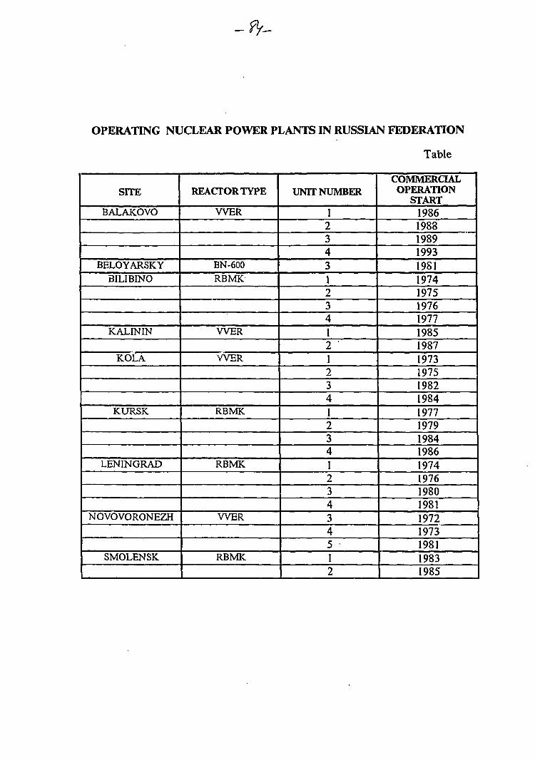
OPERATING NUCLEAR POWER PLANTS IN RUSSIAN FEDERATION
Table
SITE
BALAKOVO
BELOYARSKYBILIBINO
KALININ
KOLA
KURSK
LENINGRAD
NOVOVORONEZH
SMOLENSK
REACTOR TYPE
WER
BN-600RBMK
WER
WER
RBMK
RBMK
WER
RBMK
UNIT NUMBER
12343123412 '123412341234345 •12
COMMERCIALOPERATION
START198619831989199319S119741975197619771985198719731975198219841977197919841986197419761980198119721973198119831985
&</ -
Replacement ofl&C Systems in WWER-1000 ofKozloduy NPP
V. Miliovsky, Committee on the Use of Atomic Energy for Peaceful Purposes,Bulgaria
Abstract
Significant improvements in the Control and Instrumentation Systems areproposed by the Modernization Programme of Kozloduy units 5 and 6. Theapproach in the development of the modernization programme is given in thispaper. The proposed improvements in I&C are described and a correspondencewith the recommendations of the IAEA draft report "Ranking of Safety Issues forWWER-1000 Model 320 NPPs" WWER-SC-104 is evaluated.
1. Introduction
The Kozloduy units 5 and 6 were put in commercial operation on20 September 1988 and 30 December 1993, respectively. Both units have the samedesign elaborated in accordance with general rule OPB-73 and withnorms/standards in force at that time. The design of the plant does not entirelycomply with the current safety standards and the utility decided to implementmodernization programme to upgrade the plant. In 1993 discussions were initiatedby • " Bulgarian utility to carry out a modernization programme in order to obtainfunding from the banks. This was the reason why the utility with the engineeringassistance of the local engineering organizations, ENERGOPROEKT and RISKENGINEERING LTD, has decided to introduce additional improvements that areconsistent with the present version of the Kozloduy 5/6 modernization programme.
The basis of assessment of the initial safety level of Kozloduy 5/6 were thesafety analysis of the IAEA OSART and ASSET missions conducted at Kozloduyin 1991 and 1994 added with IAEA Safety Review Missions done on otherWWER-1000 units, evaluations made by IPSN and GRS (French and Germannuclear safety expert organizations so called RISKAUDIT) and recommendationsmade by the IAEA and the Main Designer in the draft report WWER-SC-104.
Based on this approach the safety reassessment and availability analysis ofKozloduy 5/6 includes three different stages:
- the first is concerned with the identification and prioritization of weaknessesin relation to safety and availability while making sure of the systematic scope ofthe reassessment;
- the second is concerned with the appraisal of how to resolve each safety-related and availability problems raised by the weaknesses on the basis of feasibilitystudies of corrective actions complying with safety principles and of availability-benefits evaluation whenever possible;
- the third is for implementation of corrective actions, according to a schedulewhich takes into account priorities as well as the studies, the implementation meansand the NPP operating schedule.
-ft-
Experience feedback of similar PWR unit operation (WANO - Users group),consideration of international programs led by IAEA or the EEC (PHARE andTACIS programs) may lead to propositions for new safety improvements.
In terms of reference rulings, not only for improvement studies but also forassessment of the final safety level, one could mention:
- the fundamental safety rules of the Bulgarian Regulatory Authority;- the internationally recognized IAEA documents such as "Basic Safety
Principles for Nuclear Power Plants" (INSAG-3 publication) and the "IAEA SafetyGuides - 50 - SG";
- the French rules related to design or construction (French RCC);- some of the American NRC Regulatory Guides like the NUREG 1.70 for
the drawing up of the safety report.
2. General Safety of units 516
The initial WWER 1000/V-320 design dates back to the mid of the 1970's,8 V-320 reactors are either in operation or near to completion in the former USSRand Eastern European countries. The Kozloduy reactors are among the mostrecent put in operation and they get a benefit from all implemented upgradings.
The Kozloduy units 5/6 design is, in general, consistent with standardinternational practices for safety systems and safety related systems. The basicsafety concept of defence-in-depth is realized by fundamental principles includingthe use of redundancy, diversity, physical separation, fail safe design and apressure-resistant confinement.
During construction, commissioning and operation of units 5/6 more than1600 changes to hardware and to documentation had been implemented with theaim of improving the reliability and safety of plant operation. The most importantsafety improvements are design changes in steam generators, emergency corecooling system and control rod position indication system. The main improvementsin the area of analysis and documentation are amendments in safety analysisreports reflecting start-up and operational experience, finalization of PSA (level 1)and a fully computerized system for reporting and recording of events. The mostsignificant modifications of I&C are:
- updating of SG "level" protections;- replacement of motor - actuated SG feedwater control valves with
pneumoactuated ones;- application of accelerated reactor power reduction;- application of gas fire - fighting in electronic circuitry cabinets;- applications of new three channel reactimeters;- installation of an automatic radiation monitoring system in 3 km area
around the site.A smaller number of shortcomings identified at Kozloduy 5/6 include findings
known also from operation of other WWER-1000 NPPs. The majority oshortcomings identified at Kozloduy 5/6 are mainly related to those topics whichreflect the evolution in safety standards within the last two decades.
The evaluation of the impact of all issues on plant safety considers theiinfluence on the fulfilment of the main safety functions and the underlying overal
plant defence-in-depth. In addition, the existing design issues in some areas areconsidered separately because they affect nearly every system or equipment andthus influence the capability of the main safety functions.
Because of importance of I&C systems on the fulfilment of the main safetyfunctions their issues are considered separately.
3. Shortcomings of existing I&C systems
I&C systems important to safety covers those for safety systems and those forsafety-related systems. The I&C safety classification should be completed andapproved for both cases and should be carried out into the procedures formaintenance of the I&C important to safety. The qualification list of I&Cequipment important to safety should be reviewed for all design conditions.
The qualification of I&C equipment for LOCA conditions cannot be checked,since neither specifications regarding test procedures and sequences nor testreports are available at the site.
I&C equipment has a design lifetime of ten years. Failure analysis discoveredrelay contact oxidation, low insulation resistance of wiring and terminals, etc.Without major efforts in maintenance the I&C reliability may has a serious impactto the safety.
The accident monitoring instrumentation in the control rooms is not properlydesigned. The information needed during and after an accident is distributedthroughout the control room and is not organised in a way that would support rapidand accurate diagnosis of an accident condition. Reactor pressure vessel levelindication is currently not provided and the level could be estimated only byindirect means. The I&C for monitoring and diagnosing state of systems importantto safety needs to be improved. The original design does not provide for adequatediagnostic systems to monitor the reactor coolant pressure boundary integrity andthe mechanical equipment.
The chemical monitoring system currently used is of the 1970's era. Assuranceof reliable and accurate results requires a lot of maintenance efforts. An accurateand preferably on-line chemical monitoring system is important to give theoperator a possibility for in time response to deviations in primary coolant water-chemical conditions.
The current in-core monitoring and control system can detect and manuallysuppress xenon oscillations in base load operation and infrequent power changes.However, if the plant will be used in load follow mode, the system needs to beimproved.
Recent international practice is to design an NPP with a room (technicalsupport centre) where current plant data and status is compiled to display totechnical experts who will support the operators during the management of anaccident.
4. Proposed measures in the modernization programme for I&Csystems.
I&C ReliabilityThe proposed measure are as follows:- Improvement of ECCS accumulator isolation. At present, a spurious signall
or loss of power to one sensor can fail the accumulator isolation function of all fouraccumulators;
- Classification of the equipment according to its importance for safety inaccordance with OPB-88 and PNAEG 007-09-89 and evaluation of deviations fromNUSS;
- Collection and evaluation of existing documentation concerning equipmentqualification and development and implementation of a programme for additionalqualification;
- Verification of earthquake resistance of main control room recorders andmounting or replacement;
- Determination of service life of cables, including development of diagnosis,algorithms and software;
- Replacement of Sapphire dP sensors due to susceptibility of the rupturing oftheir membrane;
- Replacement of actuator limit switches using 220 AC to avoid personnel andequipment hazard;
- Replacement of TITAN computer with a more modern system with highercapacity in speed and memory;
- Development of a Failure Mode and Effects Analysis (FMEA) for thecontrol and safety I&C. This should include both the effects of shorts or voltagedisturbances on the protection system and possible failure modes of the controlsystems;
- Development of reliability - based maintenance methods;- Development of maintenance instructions in accordance with IAEA
recommendations;- Development of "Rest Life Time" evaluation model.The Kozloduy NPP strategy for long term I&C upgrades in that one must
determine weak points and keep them working and then determine priority andschedule for evolution and technology. The replacement listed above (other thanthe TITAN replacement) are immediate requirements to replace unsatisfactorycomponents. Replacement of the TITAN computer is the biggest issue. Presently, ithas been under study for about one year. There are many organisational interfaceswithin the plant and off-site. The computer must be compatible with existingsystems which must connect with it, and must support future I&C upgrades.
The Failure Mode and Effects Analysis should be co-ordinated with thedeterministic safety analysis. Generally it is acceptable in western practice thatcontrol I&C failures cause a plant transient requiring protection, provided that:
- the frequency of failure is low such that undesirable thermal transients andchallenges to the protection system are minimised, and
- the transient caused by the failure is conservatively addressed in the safetanalysis and shown to have acceptable consequences.
The above series of actions are all based on feedback from experience,regarding inadequate quality or reliability or function. They will all provideimprovements in plant safety as well as plant availability and meet the intend of theIAEA recommendations.
Safety System Actuation Design.The reliability of the current design approach has already been assessed and
compared against a fail-safe design, where actuation takes place at loss of power.Engineering safety features actuation on loss of instrument power is not an
absolute rule in western countries. The risk of spurious actuation must be balancedagainst the risk of failure to actuate on demand. For example, it is commonpractice in the US to use "energise-to-actuate" for confinement spray. On Temelin,loss of I&C power to one Division (sensing, signal conditioning, and comparing)causes the system to drop from 2-of-3 to l-of-2; loss of a second Division dropsactuation to 1-of-l; and loss of third will cause actuation.
Loss of all electric power, of course, will render the ESF useless. However,there are ways in which instrument power could be lost without loss of AC powerto the ESF. A reliability assessment has been made regarding the likelihood of lossof instrument power, with the resulting recommendation that the electric powersupply to the I&C important to safety should be upgraded with additional andmore reliable inventors, and by backfitting other equipment of the uninterruptablepower supply system.
Segregation of the Protection System and Safety System Actuation.The proposed modification in the IAEA draft report is to install new sensing
lines to assure no reduction in safety margin or reliability. Since neither safetyproblem nor operational problem (lower availability due to spurious action) has yetbeen identified, the measure is not included in the present modernizationprogramme.
The present system could cause spurious action of reactor trip if one sensingline breaks, or possibly if one line becomes plugged. However, no single failure candefeat safety action if needed, from either reactor trip or ESF actation system.
In western countries, reactor trip and ESF actuation systems (and oftencontrol systems) often share the same tap, sensing line and sensor). The issue ismore directly related to the need to minimise spurious actuations due to a singlefailure than to segregation of systems. These areas should be incorporated intoother specifics in which design or operating deficiencies have been identified. Forexample, Kozloduy proposal to improve ECCS accumulator isolation appears to bea similar area in which a design deficiency (one which does not meet single failurecriterion) was identified and is planned for upgrade.
Human Engineering of the Control Rooms.The proposed measures are:- A structured, in-depth design review of the control room, similar to those
done for western plants, should be conducted. The objective of this review wouldbe to identify the specific deficiencies of the control room and to establish amodification plan to improve the safety situation. The recommendations of the
control room design review should be prioritised according to their importance tosafety and interim modifications should be made as soon as practical.
- A Safety Parameter Display System (SPDS) should be added to provide theoperator with the information needed to assess the critical safety functions of theplant.
- Installation of Post-Accident Monitoring System (PAMS).In-depth design review of the control room has been accomplished under an
existing programme with Gilbert-Commonwealth. A preliminary study has beencompleted and continued progress is expected. The SPDS and PAMS are twodifferent systems, and both are recommended by the IAEA draft report. Thepurpose of SPDS is to provide an information display to the operator that helpshim rapidly to diagnose an event (transient or accident). PAMS, on the other hand,provides highly reliable, safety-grade wide-range instrumentation to the operatorthat is necessary for:
- diagnosing an event and taking manual action prescribed in the EOPs;- monitoring the critical safety functions (criticality, decay heat removal);- monitoring the extend of breaches in fission product barriers;- monitoring the status of safety systems;- monitoring radioactive releases.
Water Chemistry Control and Condition Monitoring for Mechanical EquipmentThe proposed measures are:- Installation of an on-line RCS chemistry monitoring system.- Implementation of a system for continuos chemistry monitoring and control
of SG blowdown water.- Installation of a system for continuos diagnosis monitoring for main
circulation pump vibrations.- Inspection/diagnosis for main circulation pump stators winding insulation.- Reliable control of operating temperatures of winding of main transformers
and house transformer.- Replacement of sensors and analysis system for present turbine vibration
monitoring.The main coolant pump vibration monitoring system replacement is already
in progress on units 5 and 6 (by the Russian supplier AMRAIN) and will befinished in 1996.
The proposed measures address the safety issues and the intend of the IAEArecommendations have been met.
Primary Circuit Diagnostic SystemsThe proposed measures are:- Installation of a system for detection of a loose parts in primary circuit;- Installation of a system for quick detection and localisation of a leakage
from primary to secondary circuit;- Modification of existing radwaste collection system (TZ) for continuous
operation with increased sensitivity and monitoring to distinguish secondary fromprimary leaks;
-f/-
- Installation of means for leak detection in upper reactor vessel head atcontrol rod drive mechanism and instrument flange.
The intended modification of the existing radwaste system is relatively simpleand will be implemented much earlier than the proposed upper head leak detectionsystem. The Kozloduy NPP staff has already installed a humidity detector toenhance reliability of general leak detection in the upper vessel head but furthertests/inspections can not be devised that would identify the location of a leak.Therefore that need will be avoided by improving the existing seals of theinstrument flange connections and by installation of leak detection at control roddrive mechanism and instrument flange. Systems of two principles (acoustic andhumidity) are presently being evaluated. A N 16 system is now being studied fordetection of primary to secondary leaks. Improvements are desired to enhancereactor operator ability to manage the accidents.
Accident Monitoring InstrumentationThe proposed measures are:- Installation of a steam-gas mixture detector in reactor vessel to measure the
level of coolant under accident conditions;- Installation of a hydrogen detection & recombination system;- Replacement of equipment to monitor radioactivity in gas releases to
improve accuracy, equipment qualification and service life;- Installation of a sampling system for accidents;- Modernization of radiation monitoring facilities.A systematic review of accident monitoring should be conducted to identify
the parameters necessary to monitor an accident and to verify that the instrumentranges are adequate to cover all design basic events. This review should alsoconfirm that the sensor channels for the accident monitoring instrumentation aresufficiently independent from the environmental conditions that result from theaccident. The following measures are also included:
- Installation of a fibre optics cable for rapid transmission of PAMS andSPDS information in the Technical Support Center;
- Installation of an automated independent radiation monitoring system foreach safety system train;
- Development and installation of a centralized radiation monitoring system;- Installation and operation of a meteorological station;- Replacement of installed radiation monitoring system detectors which have
proved unreliability;- Provision of the metrology laboratory with the capability to maintain
ionizing radiation measuring equipment.
Automatic Reactor Protection for Power Distribution and DNB in Base LoadOperationThe measure proposed is:- The neutron monitoring system AKNP, now near to the end of its service
life, may be replaced with one that is more sensitive. Improved informationprocessing, alarm and display would also be intended.
8
The performance of the AKNP excore nuclear monitoring system isconsidered satisfactory for the present base load operation. Since it is within3 years of the end of its warranted 10 year service life for unit 5, the Russianmanufacturer, SNIIP, will study it to see if its warranty can be extended. If it isdecided to be replaced it will be replaced with more sensitive detectors. At presentno need has been identified for axial offset monitored by the excore nuclearinstrumentation and it is not a consideration for an upgraded system. The adversepower distributions wili be considered in the upgraded safety analysis. On thatbasis the BNSA will decide whether administrative control provides adequateprotection.
Incore Monitoring of Power Distribution in Load Follow ModeThe proposed measure is:- Replacement of the incore monitoring system including thermocouples,
neutron detectors and computer processor. (This may be done as part ofconversion to a three year fuel cycle.)
A decision on replacing the incore detectors must be made before the end ofthe 10 year service life of the present detectors and system. If the plant will beconverted to load follow operation new/different fuel would be required anddifferent incore detectors and computer processor would be provided.
5. Conclusions
The intended programmes in the area of I&C together with other upgradeseither completed or already in progress address all the IAEA I&C issues of highersafety significance. Two of the IAEA I&C issues of low safety significance are notaddressed: potential for spurious actuation due to a single failure and core axialpower protection against DNB during base load operation. Kozloduy NPP shouldmonitor progress on these issues in other WWER-1000/320 NPPs and considertheir applicability to Kozloduy NPP.
Modernization of Kozloduy 5/6 would provide a power generation sourcewhere one could expect a very high level of reliability. The targeted safetyimprovements can only go to increasing these factors, the in-service availability andload factors. Successful completion of the modernization programme in good timewould therefore constitute a considerable beneficial contribution to means ofenergy production in Bulgaria in safe and reliable conditions.
IAEA ADVISORY GROUP MEETINGON
MODERNIZATION OF INSTRUMENTATION AND CONTROL SYSTEMSIN NUCLEAR POWER PLANTS
VIENNA, 25 TO 29 MARCH 1996
NPP Ii&C SYSTEM INNOVATIONSIN THE CZECH REPUBLIC
A REGULATORY PERSPECTIVE
PRESENTED BY C. KARPETASONS
PRAGUE, CZECH REPUBLIC
The goal of this presentation is to describe:
the on-going I&C system replacement project at the NPPTemelin
the preparatory phase of a project for I&C system innovation atthe NPP Dukovany
licensing aspects of NPP I&C system replacement/innovationprojects in the Czech Republic
I&C system replacement project at the NPPTemelin
Topics to be addressed:
• brief description of the NPP Temelin
• Ii&C system upgrades
• diagnostic system upgrades
• quality assurance aspects of the I&C system replacement
Brief description of the NPP Temelin
general information about the plant
the plant NSSS
the plant secondary side
the plant original I&C system
a summary of deficiencies of the original I&C system design
I&C design upgrades
overview of the adopted approach
I&C system architecture
* unit information system :§
* I&C parts of the plant safety systems
Primary Reactor Protection System (PRPS)Diverse Protection System (DPS)Post-Accident Monitoring System (PAMS)Non-Programmable Logic (NPL)
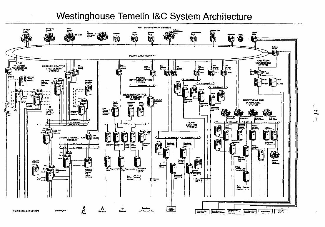
Westinghouse Temelin I&C System ArchitectureUNIT INFORMATION SYSTEM
DIVERSE PROTECTION WLJ.SYSTEM ^ - B
Plant Loads and Sensors Swllcho«ar Contact I ^^M^HM^M I I I ^ ^ A ^ ^ ^ ^ ^ I I S^B^OiMi^^ I I ^n^H^HM^tai I I , r - ^̂
I&C design upgrades (cont.)
* Reactor Control and Limitation System (RCLS)
* Plant Control System (PCS)
* Plant Control Centers (MCR, ECR, TSC)
Diagnostic systems
• Control Rod Drive Monitoring System (CRDMS)
• Digital Metal Impact Monitoring System (DMIMS)
• Rotating Equipment Vibration Monitoring System (RECOP)
• Material Fatigue Evaluation System (MAFES-TSF)
• Material Fatigue Evaluation System (MAFES-DMS)
• Reactor Vibration Monitoring System (RVMS)
• Leakage Monitoring System of Pipes (LEMOP)
6\
Oualitv assurance of the I&C systemreplacement project
Topics to be addressed:
• basic provisions of the Regulation No. 436/1990
• QA programs of organizations involved in the replacementproject
• QA policy adopted in the I&C area
Basic provisions of the Regulation No. 436
• items important to safety are classified into three safety classes
• three types of QA programs are identified (general, partial, andindividual)
• both organizational and technical aspects of QA programsimplementation are addressed
• format and contents of documentation on implementation of eachtype of QA programs are defined
A.o
QA programs of organizations involved inthe replacement project
• the utility - Czech Power Company (CEZ)
• the general supplier - SKODA Company
• subcontractors of the general supplier
* Westinghouse Electric Corporation (WEC)* Energoprojekt (EGP)* Regula Praha, Metra Blansko, VUMS, Diamo, I&C Energo
and others
QA policy adopted in the I&C area
• the role of EGP and WEC in the I&C system design
• manufacture of the I&C equipment
* in the USA
outside the Czech Republic territory
in the Czech Republic
installation
i
Preparatory activities for I&C systeminnovation at the NPP Dukovany
Topics to be addressed:
• brief description of the NPP Dukovany and its I&C system
• overview of findings of the plant I&C system evaluations
• outline of a proposal for I&C system replacement project
?
Brief description of the NPP Dukovany
general information on the plant
NSSS of the plant
plant secondary side
plant I&C systems
* I&C parts of safety systems*• control systems* information systems
r
Overview of the I&C system evaluations
IAEA extrabudgetary program on the safety of VVER model 213NPPs
basic engineering for replacement of the I&C system for V 213nuclear reactors - phase 1
SONS findings from evaluation of the operational SAR for UnitNo. 1
results of PSA - level 1 study
Outline of a proposal for I&C replacementRecommendations for I&C system replacement generated by thePHARE project - phase 2
• objectives of the replacement project
• definition of the final design concept
• formulation of detailed system requirements
• specification of the project QA program
• inquiry documentation
• planning documentation
o
Licensing aspects of I&C system replacementprojects in the Czech Republic
Topics to be addressed:
• the existing regulatory framework
• specific aspects of the NPP Dukovany case
• specific aspects of the NPP Temelin case
• database of licensing issues to be considered in the assessment ofnew I&C systems
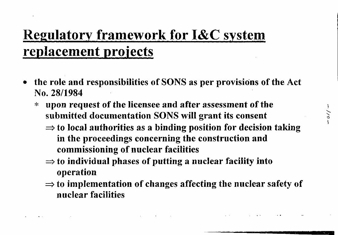
Regulatory framework for I&C systemreplacement projects
the role and responsibilities of SONS as per provisions of the ActNo. 28/1984* upon request of the licensee and after assessment of the
submitted documentation SONS will grant its consentto local authorities as a binding position for decision takingin the proceedings concerning the construction andcommissioning of nuclear facilitiesto individual phases of putting a nuclear facility intooperationto implementation of changes affecting the nuclear safety ofnuclear facilities
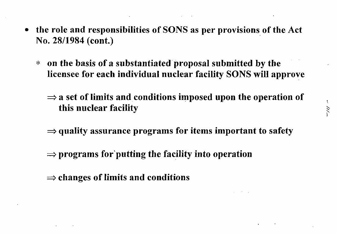
the role and responsibilities of SONS as per provisions of the ActNo. 28/1984 (cont.)
* on the basis of a substantiated proposal submitted by thelicensee for each individual nuclear facility SONS will approve
a set of limits and conditions imposed upon the operation ofthis nuclear facility
quality assurance programs for items important to safety
programs for putting the facility into operation
changes of limits and conditions
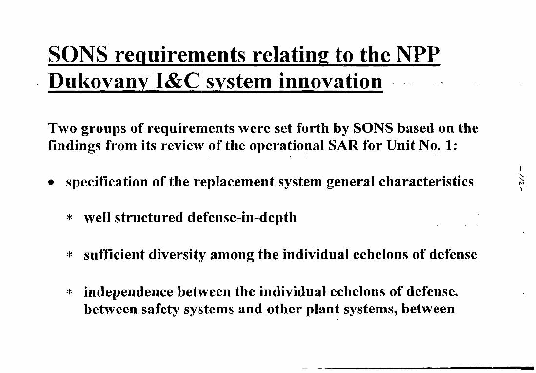
SONS requirements relating to the NPPDukovany I&C system innovation
Two groups of requirements were set forth by SONS based on thefindings from its review of the operational SAR for Unit No. 1:
• specification of the replacement system general characteristics
* well structured defense-in-depth
* sufficient diversity among the individual echelons of defense
* independence between the individual echelons of defense,between safety systems and other plant systems, between
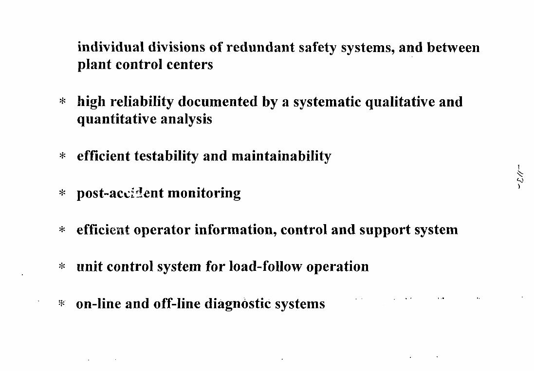
individual divisions of redundant safety systems, and betweenplant control centers
* high reliability documented by a systematic qualitative andquantitative analysis
* efficient testability and maintainability
post-accident monitoring
efficient operator information, control and support system
unit control system for load-follow operation
on-line and off-line diagnostic systems
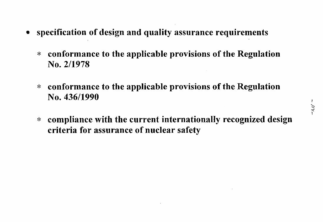
specification of design and quality assurance requirements
* conformance to the applicable provisions of the RegulationNo. 2/1978
* conformance to the applicable provisions of the RegulationNo, 436/1990
* compliance with the current internationally recognized designcriteria for assurance of nuclear safety
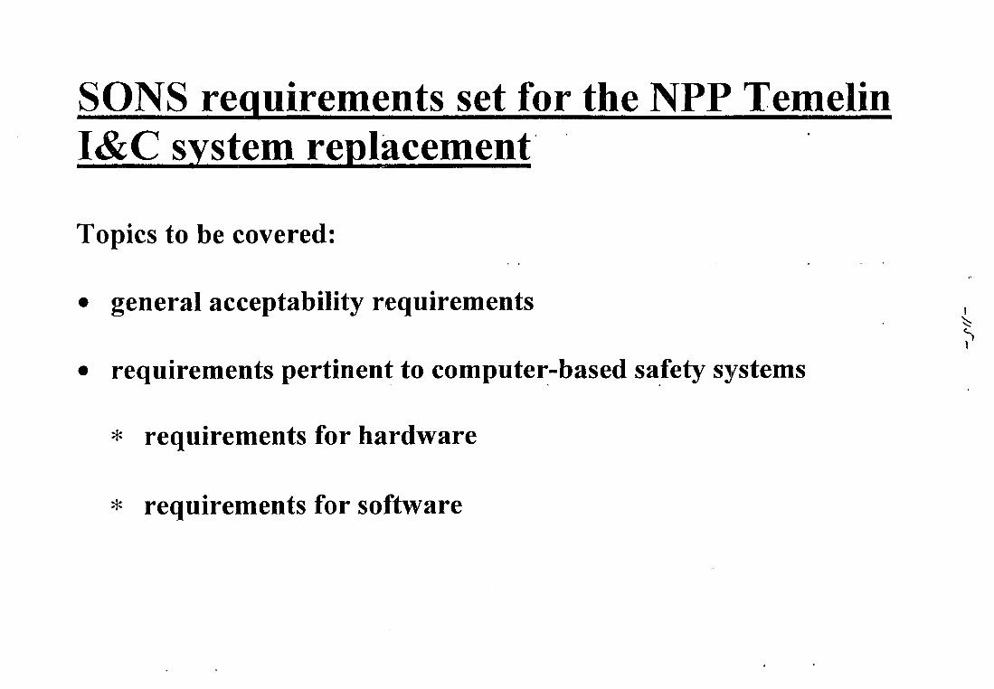
SONS requirements set for the NPP TemelinI&C system replacement
Topics to be covered:
• general acceptability requirements
• requirements pertinent to computer-based safety systems
* requirements for hardware
* requirements for software
^
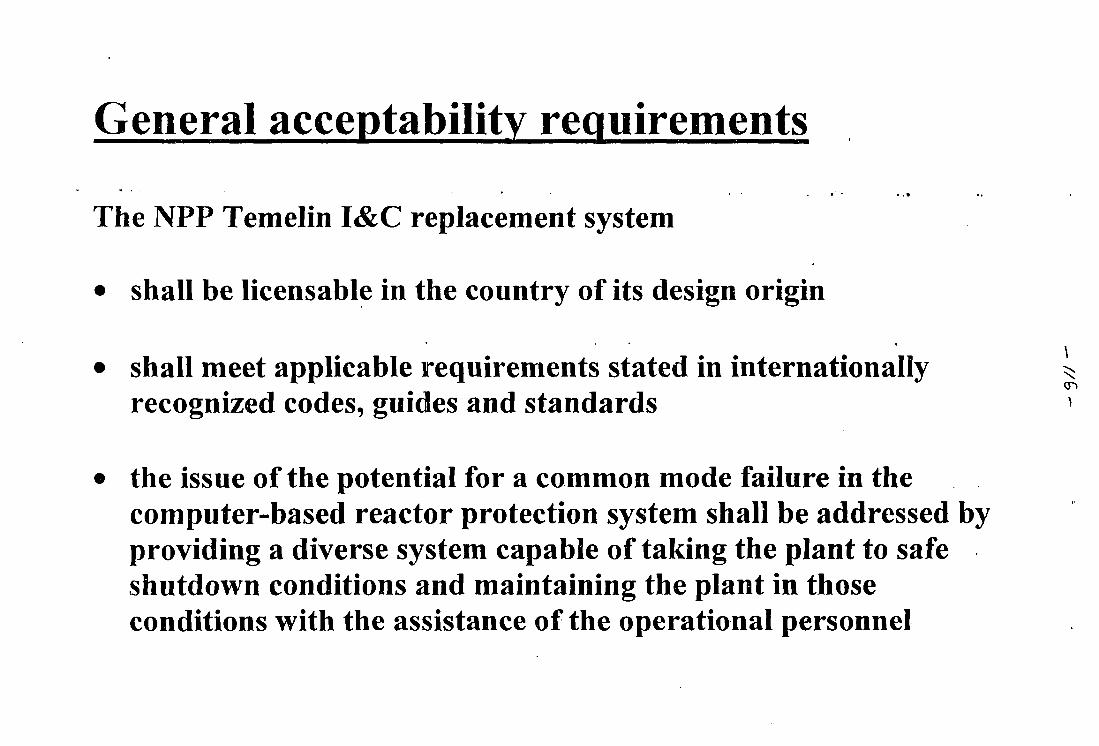
General acceptability requirements
The NPP Temelin I&C replacement system
• shall be licensable in the country of its design origin
• shall meet applicable requirements stated in internationally ^recognized codes, guides and standards
the issue of the potential for a common mode failure in thecomputer-based reactor protection system shall be addressed byproviding a diverse system capable of taking the plant to safeshutdown conditions and maintaining the plant in thoseconditions with the assistance of the operational personnel
)
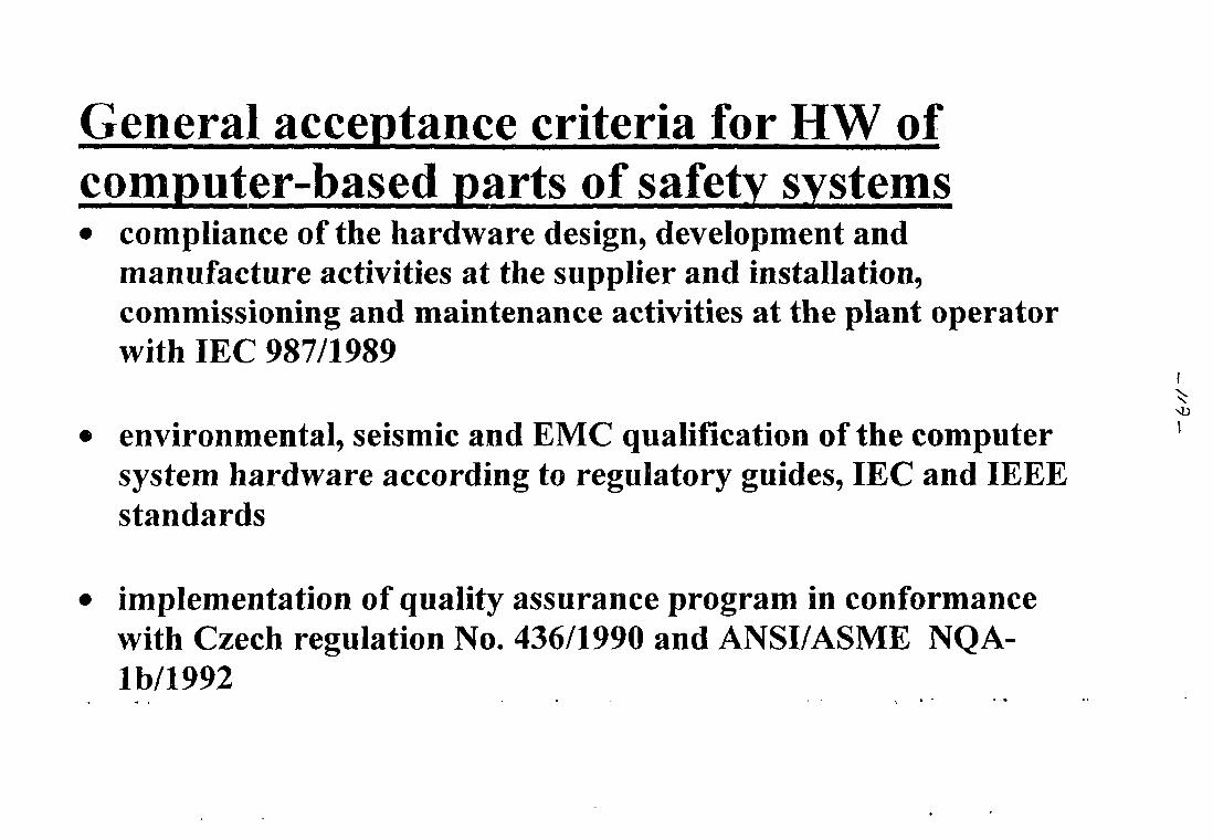
General acceptance criteria for HW ofcomputer-based parts of safety systems• compliance of the hardware design, development and
manufacture activities at the supplier and installation,commissioning and maintenance activities at the plant operatorwith IEC 987/1989
• environmental, seismic and EMC qualification of the computersystem hardware according to regulatory guides, IEC and IEEEstandards
• implementation of quality assurance program in conformancewith Czech regulation No. 436/1990 and ANSI/ASME NQA-lb/1992
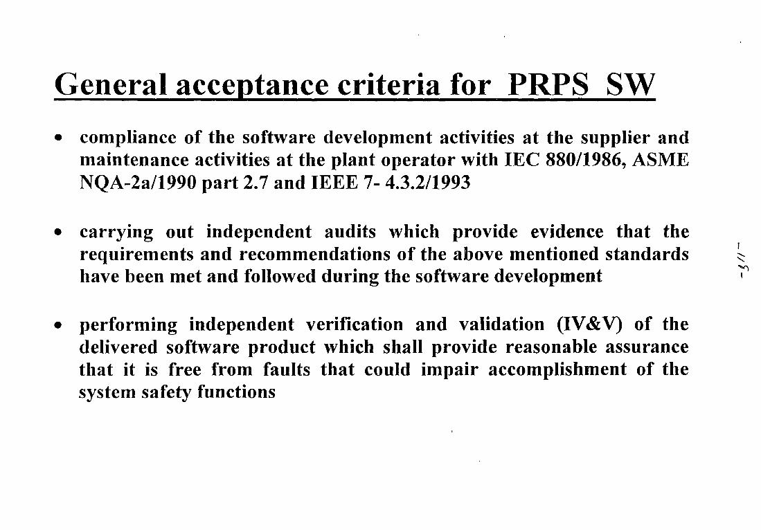
General acceptance criteria for PRPS SW
• compliance of the software development activities at the supplier andmaintenance activities at the plant operator with IEC 880/1986, ASMENQA-2a/1990 part 2.7 and IEEE 7- 4.3.2/1993
• carrying out independent audits which provide evidence that therequirements and recommendations of the above mentioned standardshave been met and followed during the software development
• performing independent verification and validation (IV&V) of thedelivered software product which shall provide reasonable assurancethat it is free from faults that could impair accomplishment of thesystem safety functions
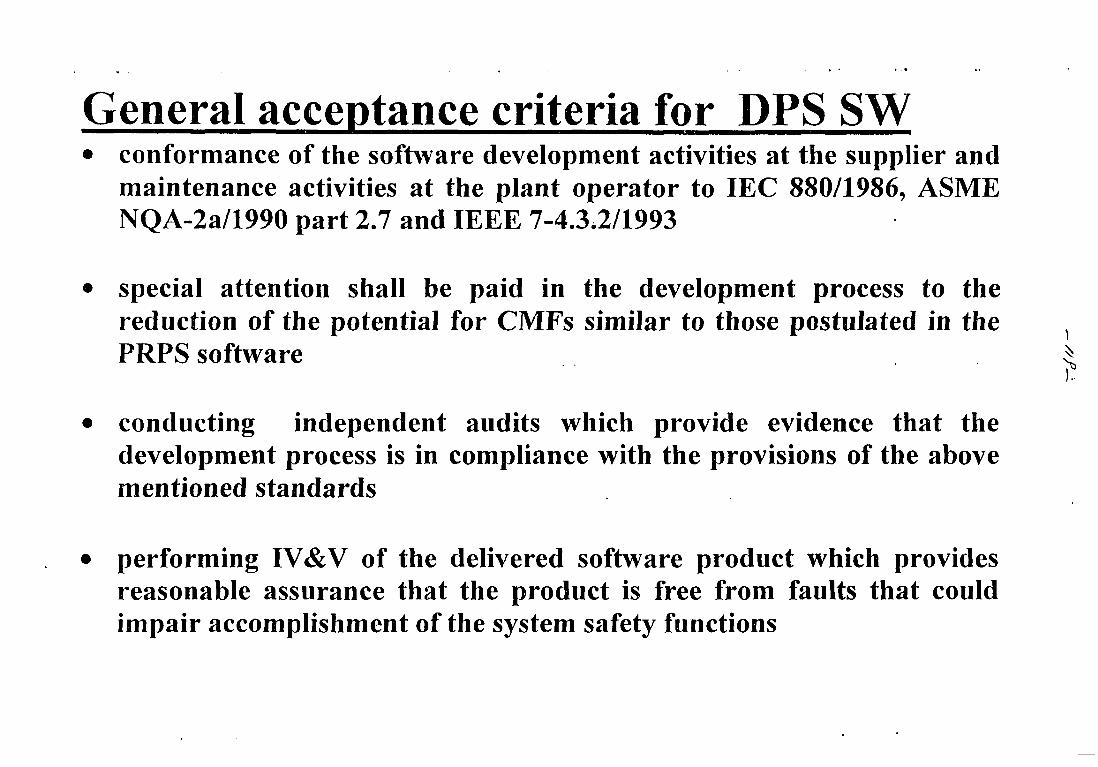
General acceptance criteria for DPS SW• conformance of the software development activities at the supplier and
maintenance activities at the plant operator to IEC 880/1986, ASMENQA-2a/1990 part 2.7 and IEEE 7-4.3,2/1993
• special attention shall be paid in the development process to thereduction of the potential for CMFs similar to those postulated in the }
PRPS software $
• conducting independent audits which provide evidence that thedevelopment process is in compliance with the provisions of the abovementioned standards
• performing IV&V of the delivered software product which providesreasonable assurance that the product is free from faults that couldimpair accomplishment of the system safety functions
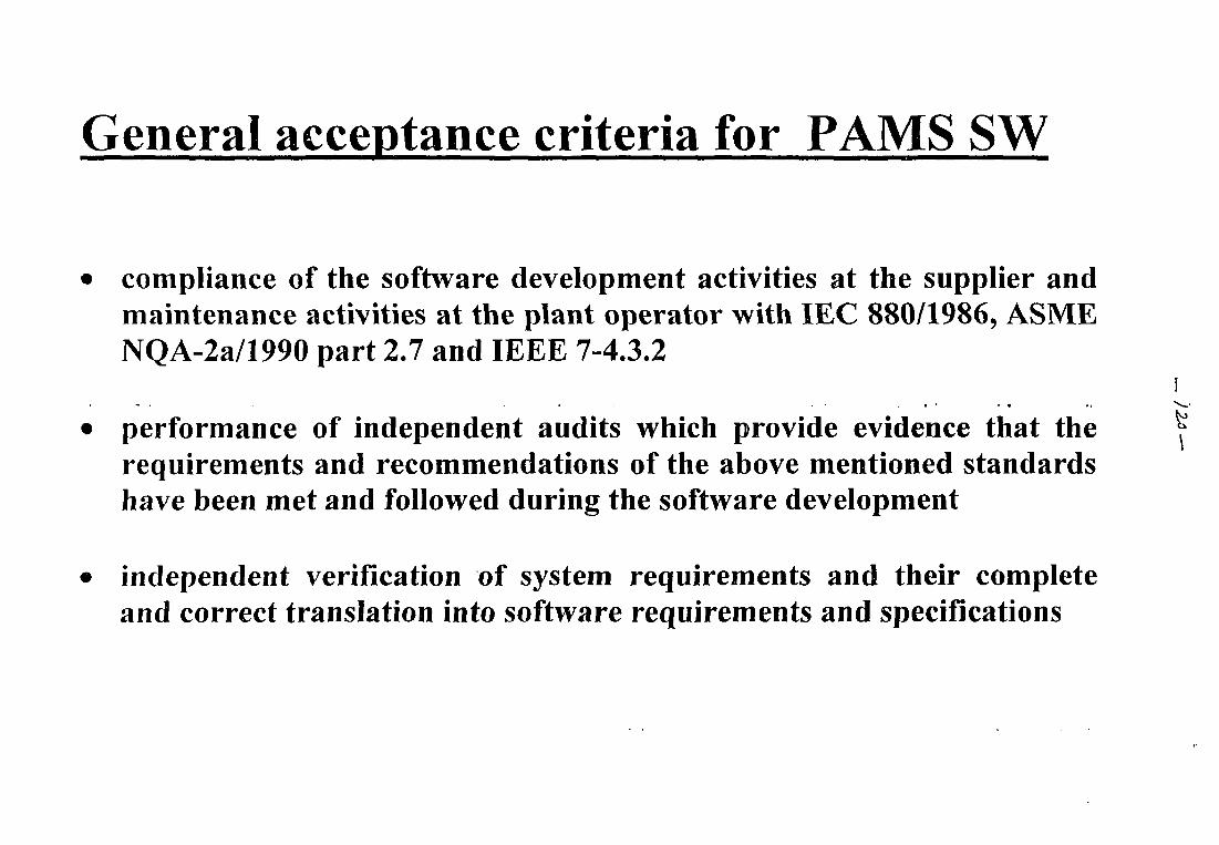
General acceptance criteria for PAMS SW
compliance of the software development activities at the supplier andmaintenance activities at the plant operator with IEC 880/1986, ASMENQA-2a/1990 part 2.7 and IEEE 7-4.3.2
performance of independent audits which provide evidence that therequirements and recommendations of the above mentioned standardshave been met and followed during the software development
independent verification of system requirements and their completeand correct translation into software requirements and specifications
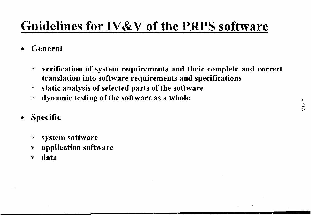
Guidelines for IV&V of the PRPS software
• General
* verification of system requirements and their complete and correcttranslation into software requirements and specifications
* static analysis of selected parts of the software
* dynamic testing of the software as a whole
• Specific
* system software* application software* data
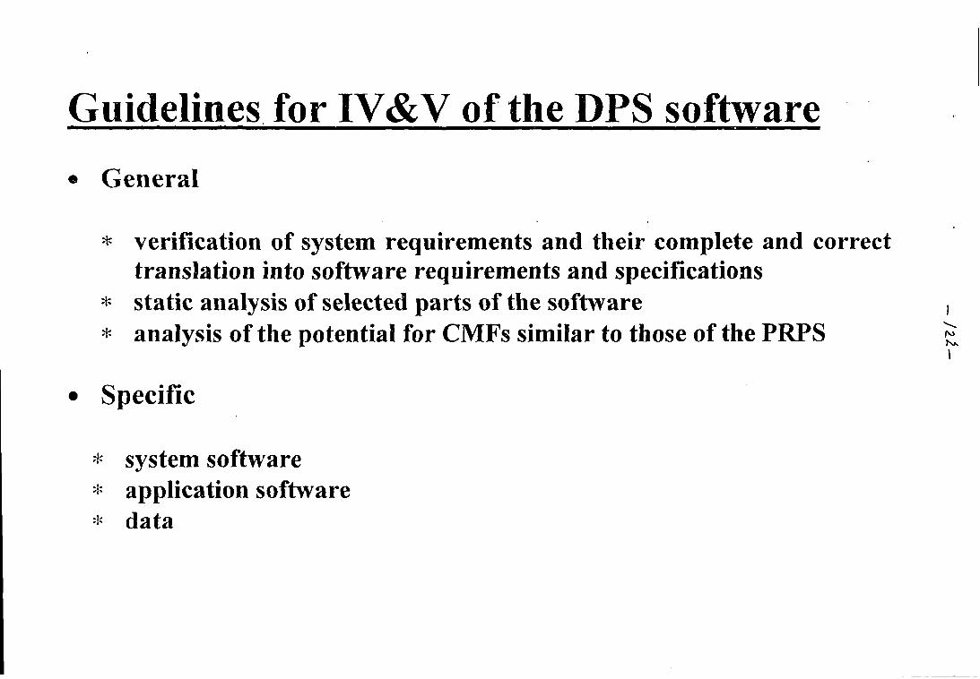
Guidelines for IV&V of the DPS software
• General
* verification of system requirements and their complete and correcttranslation into software requirements and specifications
* static analysis of selected parts of the software* analysis of the potential for CMFs similar to those of the PRPS
• Specific
* system software* application software* data
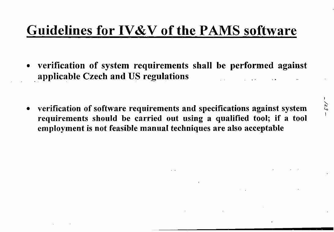
Guidelines for IV&V of the PAMS software
verification of system requirements shall be performed againstapplicable Czech and US regulations
verification of software requirements and specifications against systemrequirements should be carried out using a qualified tool; if a toolemployment is not feasible manual techniques are also acceptable
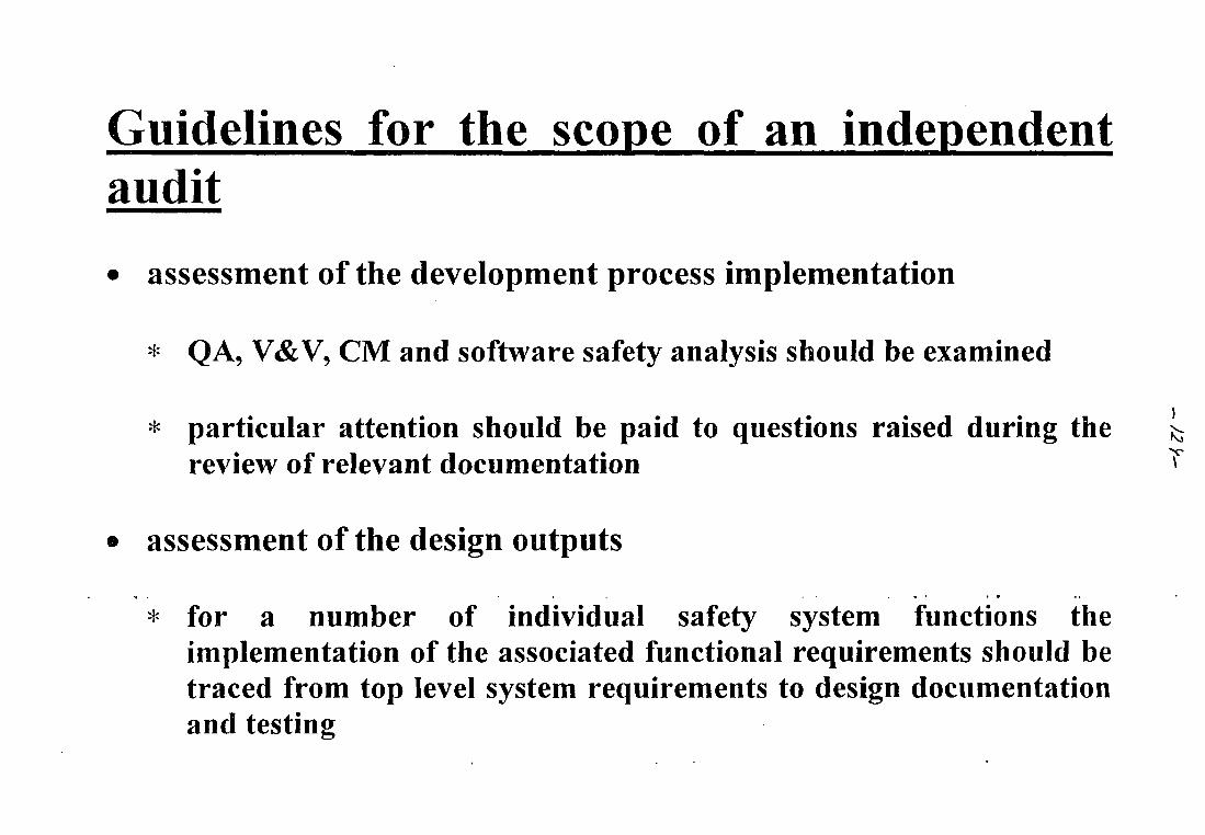
Guidelines for the scope of an independentaudit
• assessment of the development process implementation
* QA, V&V, CM and software safety analysis should be examined
* particular attention should be paid to questions raised during the ^review of relevant documentation ^
• assessment of the design outputs
* for a number of individual safety system functions theimplementation of the associated functional requirements should betraced from top level system requirements to design documentationand testing
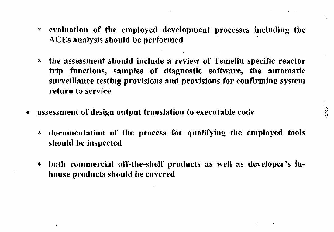
* evaluation of the employed development processes including theACEs analysis should be performed
* the assessment should include a review of Temelin specific reactortrip functions, samples of diagnostic software, the automaticsurveillance testing provisions and provisions for confirming systemreturn to service
assessment of design output translation to executable code
* documentation of the process for qualifying the employed toolsshould be inspected
* both commercial off-the-shelf products as well as developer's in-house products should be covered
Database of licensing issues
A database of licensing issues has been developed because of:
• the need for a tool for organizing, documenting, and reporting ofthe NPP Temelin I&C licensing review process
• SONS position on licensibility of the NPP Temelin I&C systems
• specific characteristics of the NPP Temelin I&C system design
• adopted review methodology
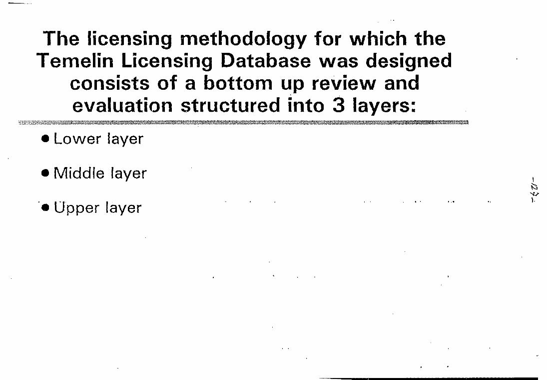
The licensing methodology for which theTemelin Licensing Database was designed
consists of a bottom up review andevaluation structured into 3 layers:
Lower layer
Middle layer
Upper layer
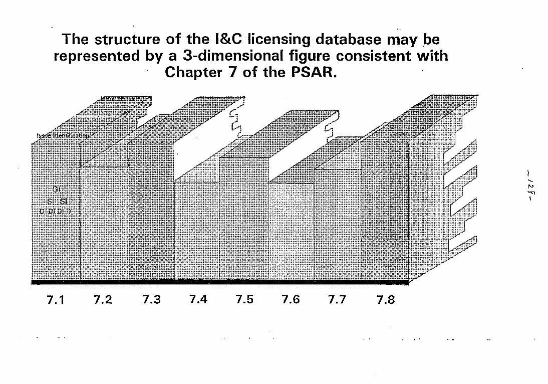
The structure of the I&C licensing database may berepresented by a 3-dimensional figure consistent with
Chapter 7 of the PSAR.
\sfid6WenttficVt
7.1 7.2
H u l l :
7.3 7.4 7.5 7.6 7.7 7.8
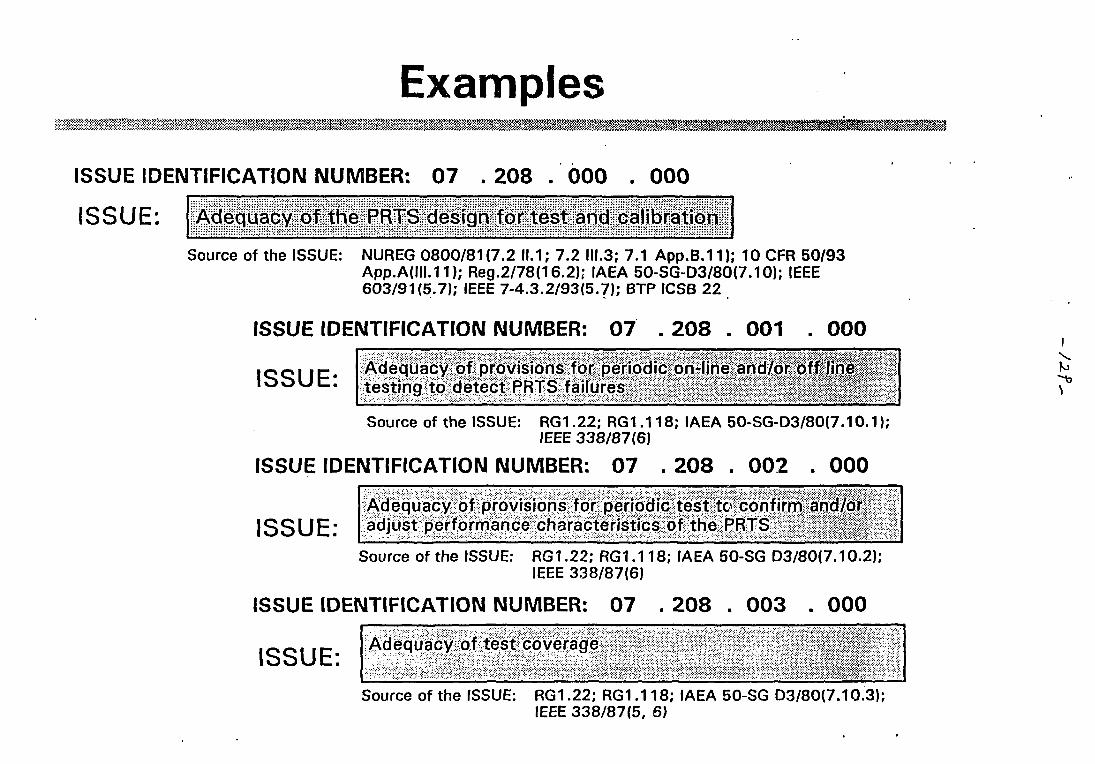
Examples>/^ yt > %«*>
ISSUE IDENTIFICATION NUMBER: 07 . 208 . 000 . 000
ISSUE: Adequacy of the PRTS design for test and calibration
Source of the ISSUE: NUREG 0800/81(7.2 11.1; 7.2 III.3; 7.1 App.B.11); 10 CFR 50/93App.A(III.H); Reg.2/78(16.2); IAEA 50-SG-D3/80(7.10); IEEE603/91(5.7); IEEE 7-4.3.2/93(5.7); BTP ICSB 22
ISSUE IDENTIFICATION NUMBER: 07 . 208 . 001 . 000
ISSUE: Adequacy of provisions for periodic on-line and/or off linetesting to detect PRTS failures J
Source of the ISSUE: RG1.22; RG1.118; IAEA 50-SG-D3/80(7.10.1);IEEE 338/87(6)
ISSUE IDENTIFICATION NUMBER: 07 . 208 . 002 . 000
ISSUE:Adequacy of provisions for periodic test to confirm and/oradjust performance characteristics of the PRTS
Source of the ISSUE: RG1.22; RG1.118; IAEA 50-SG D3/80(7.10.2);IEEE 338/87(6)
ISSUE IDENTIFICATION NUMBER: 07 . 208 . 003 . 000
ISSUE:Adequacy of test coverage
Source of the ISSUE: RG1.22; RG1.118; IAEA 50-SG D3/80(7.10.3);IEEE 338/87(5, 6)
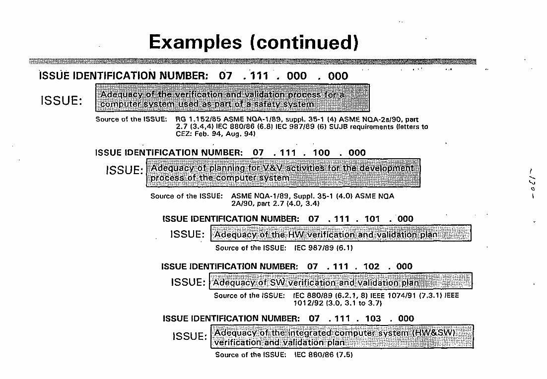
Examples (continued)
ISSUE IDENTIFICATION NUMBER: 07 .111
ISSUE:
000 . 000
Adequacy of ihe verification and valtdatfon'process^fo^a^ftcomputer system used as part of a safety system; \}"-1\"'
Source of the ISSUE: RG 1.152/85 ASME NQA-1/89, suppl. 35-1 (4) ASME NQA-2a/90. part2.7 (3.4,4) IEC 880/86 (6.8) IEC 987/89 (6) SUJB requirements (letters toCEZ: Feb. 94, Aug. 94)
ISSUE IDENTIFICATION NUMBER: 07 . 111 . 100 000
ISSUE: Adequacy of planning forV&V activities for the development;,process of the computer system
Source of the ISSUE: ASME NQA-1/89, Suppl. 35-1 (4.0) ASME NQA2A/90, part 2.7 (4.0, 3.4)
ISSUE IDENTIFICATION NUMBER: 07 . 1 1 1 . 101 . 0 0 0
ISSUE: Adequacy of the HW verification and validation plan
Source of the ISSUE: IEC 987/89 (6.1)
ISSUE IDENTIFICATION NUMBER: 07 . 1 1 1 . 102 . 000
ISSUE: Adequacy of SW verification and validation plan
Q\
Source of the ISSUE: IEC 880/89 (6.2.1, 8) IEEE 1074/91 (7.3.1) IEEE1012/92 (3.0, 3.1 to 3.7)
ISSUE IDENTIFICATION NUMBER: 07 . 1 1 1 . 103 . 000
ISSUE: Adequacy of the integrated computer system (HW&SW)verification and validation planSource of the ISSUE: IEC 880/86 (7.5)
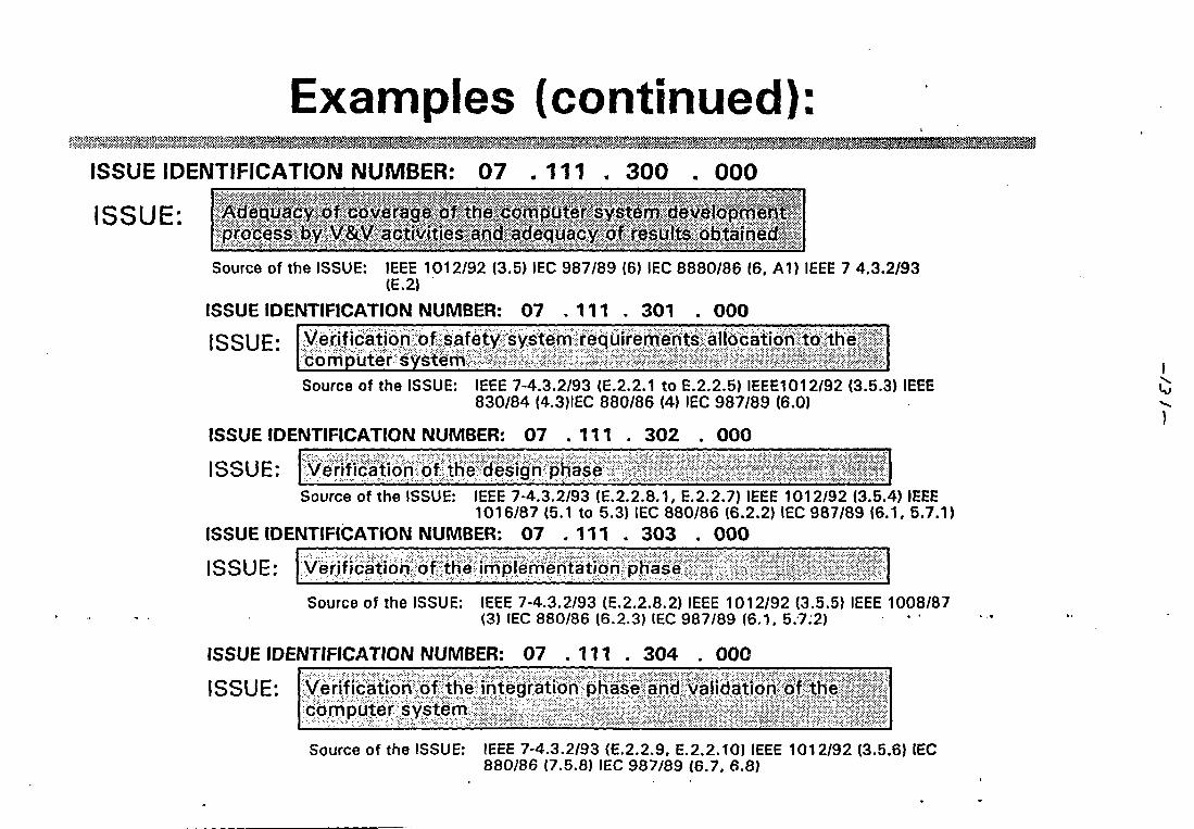
Examples (continued):ISSUE IDENTIFICATION NUMBER: 07 .111 300 . 000
ISSUE: Adequacy of coverage of the,computersystem development;process by V&V activities and adequacy of results obtained.
Source of the ISSUE: IEEE 1012/92 (3.5) IEC 987/89 (6) IEC 8880/86 (6. A1) IEEE 7 4.3.2/93(E.2)
ISSUE IDENTIFICATION NUMBER: 07 . 111 . 301 . 000
ISSUE: Verification of safety system requirements allocation to thecomputer system -Source of the ISSUE: IEEE 7-4.3.2/93 (E.2.2.1 to E.2.2.5) IEEE1012/92 (3.5.3) IEEE
830/84 (4.3)IEC 880/86 (4) IEC 987/89 (6.0)
ISSUE IDENTIFICATION NUMBER: 07 .111 . 302 . 000
ISSUE: Verification of the design phase
Source of the ISSUE: IEEE 7-4.3.2/93 (E.2.2.8.1, E.2.2.7) IEEE 1012/92 (3.5.4) IEEE1016/87 (5.1 to 5.3) IEC 880/86 (6.2.2) IEC 987/89 (6.1, 5.7.1)
ISSUE IDENTIFICATION NUMBER: 07 .111 . 303 . 000
ISSUE: Verification of the implementation phase
Source of the ISSUE: IEEE 7-4.3.2/93 (E.2.2.8.2) IEEE 1012/92 (3.5.5) IEEE 1008/87(3) IEC 880/86 (6.2.3) IEC 987/89 (6.1. 5.7.2)
ISSUE IDENTIFICATION NUMBER: 0 7 . 1 1 1 . 3 0 4 . 0 0 0
ISSUE: Verification of the integration phase and validation of thecomputer system
Source of the ISSUE: IEEE 7-4.3.2/93 (E.2.2.9. E.2.2.10) IEEE 1012/92 (3.5.6) IEC880/86 (7.5.8) IEC 987/89 (6.7. 6.8)
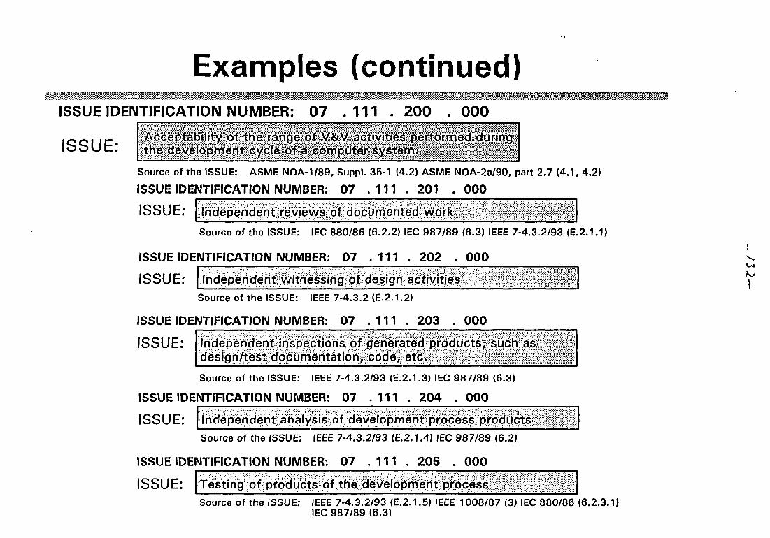
Examples (continued)ISSUE IDENTIFICATION NUMBER: 07 . 111 . 200
ISSUE:
000Acceptability of the range of V&V activities performed duringthe development cycle of a computer system,,, V; ' '< '* *<t
Source of the ISSUE: ASME NQA-1/89, Suppl. 35-1 (4.2) ASME NQA-2a/90, part 2.7 (4.1, 4.2)
ISSUE IDENTIFICATION NUMBER: 07 . 111 . 201 . 000
ISSUE: Independent reviews of documented work
Source of the ISSUE: IEC 880/86 (6.2.2) IEC 987/89 (6.3) IEEE 7-4.3.2/93 (E.2.1.1)
ISSUE IDENTIFICATION NUMBER: 07 .111 . 202 . 000
ISSUE: Independent witnessing of design activities
J
Source of the ISSUE: IEEE 7-4.3.2 (E.2.1.2)
ISSUE IDENTIFICATION NUMBER: 07 .111 . 203
ISSUE:
000
Independent inspections of generated products, such asdesign/test documentation, code, etc.
Source of the ISSUE: IEEE 7-4.3.2/93 (E.2.1.3) IEC 987/89 (6.3)
ISSUE IDENTIFICATION NUMBER: 07 .111 . 204 . 000
ISSUE: Independent analysis of development process productsSource of the ISSUE: fEEE 7-4.3.2/93 (E.2.1.4) IEC 987/89 (6.2)
ISSUE IDENTIFICATION NUMBER: 07 .111 . 205 . 000
ISSUE: Testing of products of the development processSource of the ISSUE: IEEE 7-4.3.2/93 (E.2.1.5) IEEE 1008/87 (3) IEC 880/86 (6.2.3.1)
IEC 987/89 (6.3)
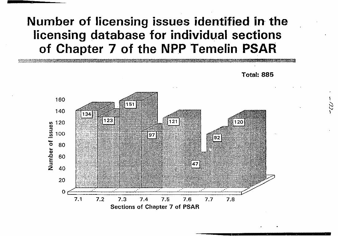
Number of licensing issues identified in thelicensing database for individual sectionsof Chapter 7 of the NPP Temelin PSAR
j . . . . . . , , ; , - > • ; - -£»•»<-.£;*
Total: 885
160
140
to 120OJ
% 100
*o 80w
-9 6040
20
,,-yv
47
7.1 7.2 7.3 7.4 7.5 7.6 7.7 7.8Sections of Chapter 7 of PSAR

r
MMIS Development: its status
IAEA Advisory Group Meeting
on
"Modernization of Instrumentation and Control Systems in Nuclear Power Plant" ^
25-29 March 1996 ^
Vienna/Austria
In Soo Koo/ Chang Hwoi Kim
Man-machine Interface System Development/Advanced I&C Systems Development
Korea Atomic Energy Research Institute
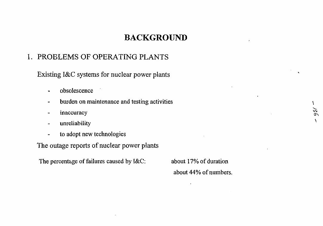
BACKGROUND
1. PROBLEMS OF OPERATING PLANTS
Existing I&C systems for nuclear power plants
obsolescence
burden on maintenance and testing activities
inaccuracy
unreliability
to adopt new technologies
The outage reports of nuclear power plants
The percentage of failures caused by I&C: about 17% of duration
about 44% of numbers.
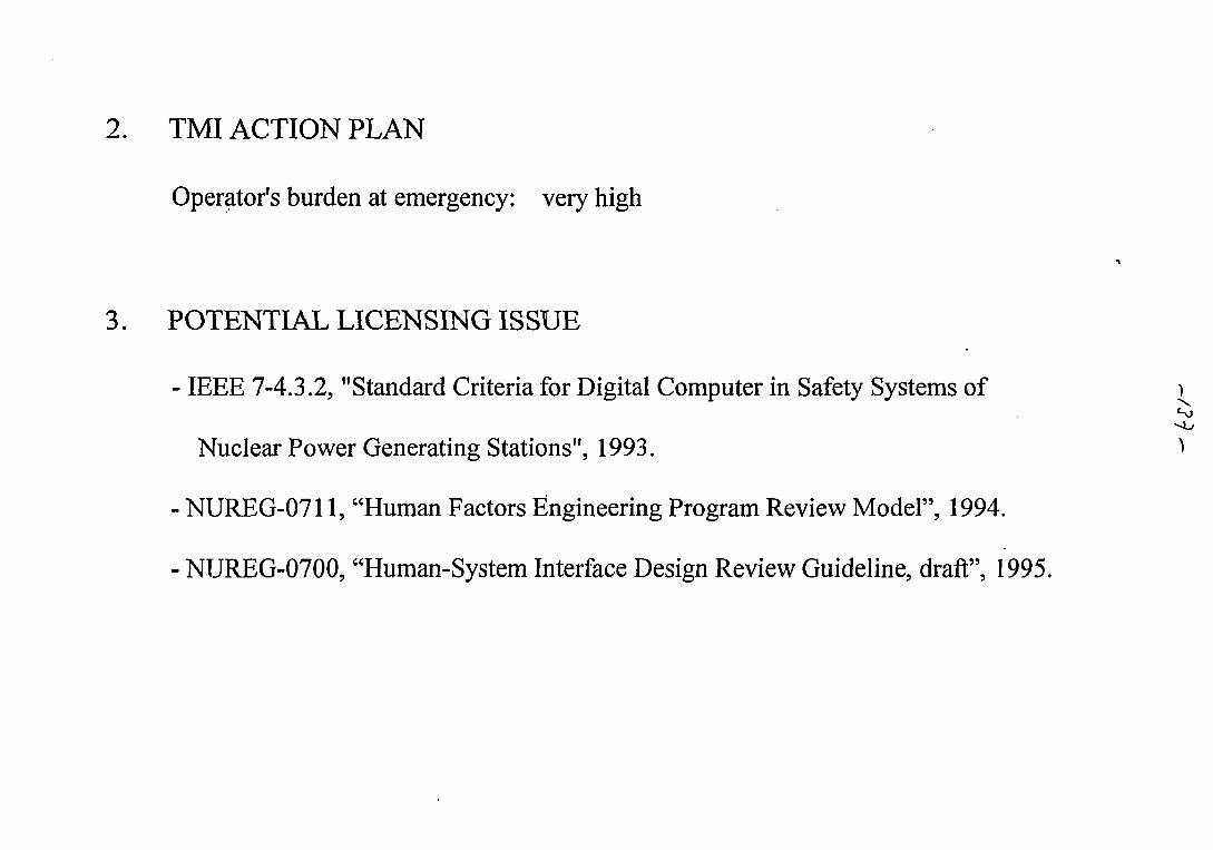
2. TMI ACTION PLAN
Operator's burden at emergency: very high
3. POTENTIAL LICENSING ISSUE
- IEEE 7-4.3.2, "Standard Criteria for Digital Computer in Safety Systems of )
Nuclear Power Generating Stations", 1993. ^
- NUREG-0711, "Human Factors Engineering Program Review Model", 1994.
- NUREG-0700, "Human-System Interface Design Review Guideline, draft", 1995.
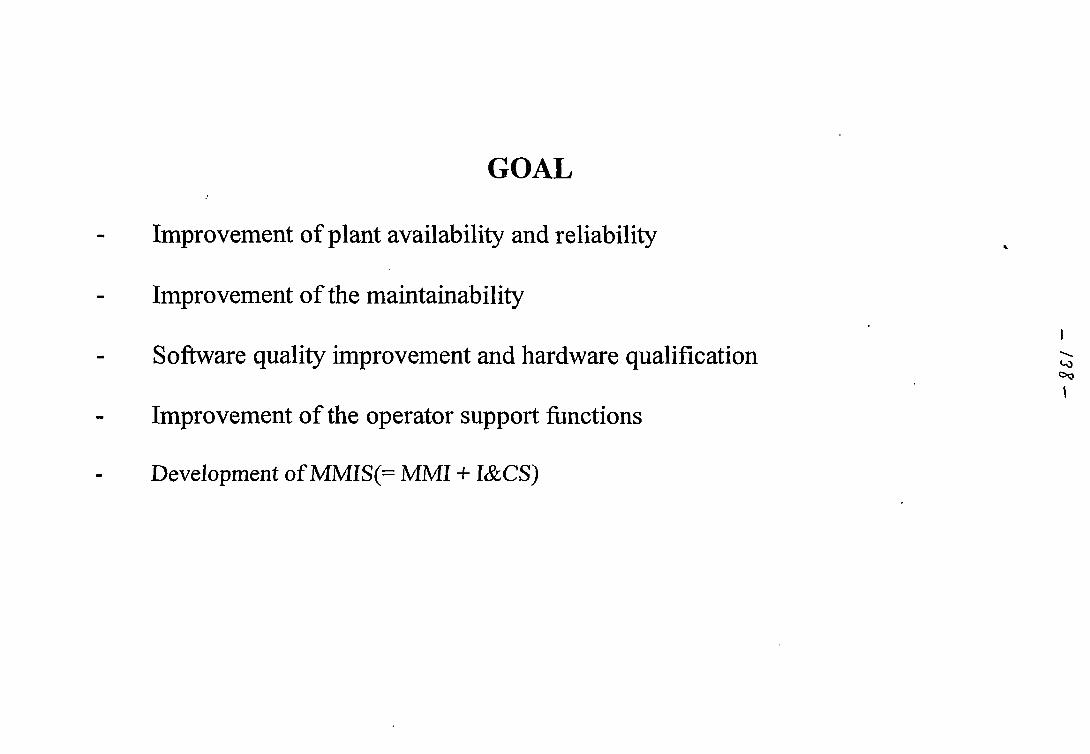
GOAL
Improvement of plant availability and reliability
Improvement of the maintainability
Software quality improvement and hardware qualification
Improvement of the operator support functions
Development of MMIS(= MMI + I&CS)
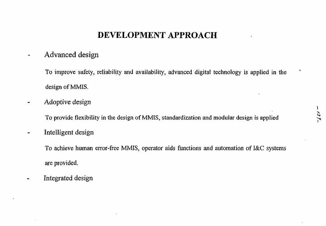
DEVELOPMENT APPROACH
Advanced design
To improve safety, reliability and availability, advanced digital technology is applied in the
design of MMIS.
Adoptive design
To provide flexibility in the design of MMIS, standardization and modular design is applied ^
Intelligent design
To achieve human error-free MMIS, operator aids functions and automation of I&C systems
are provided.
Integrated design
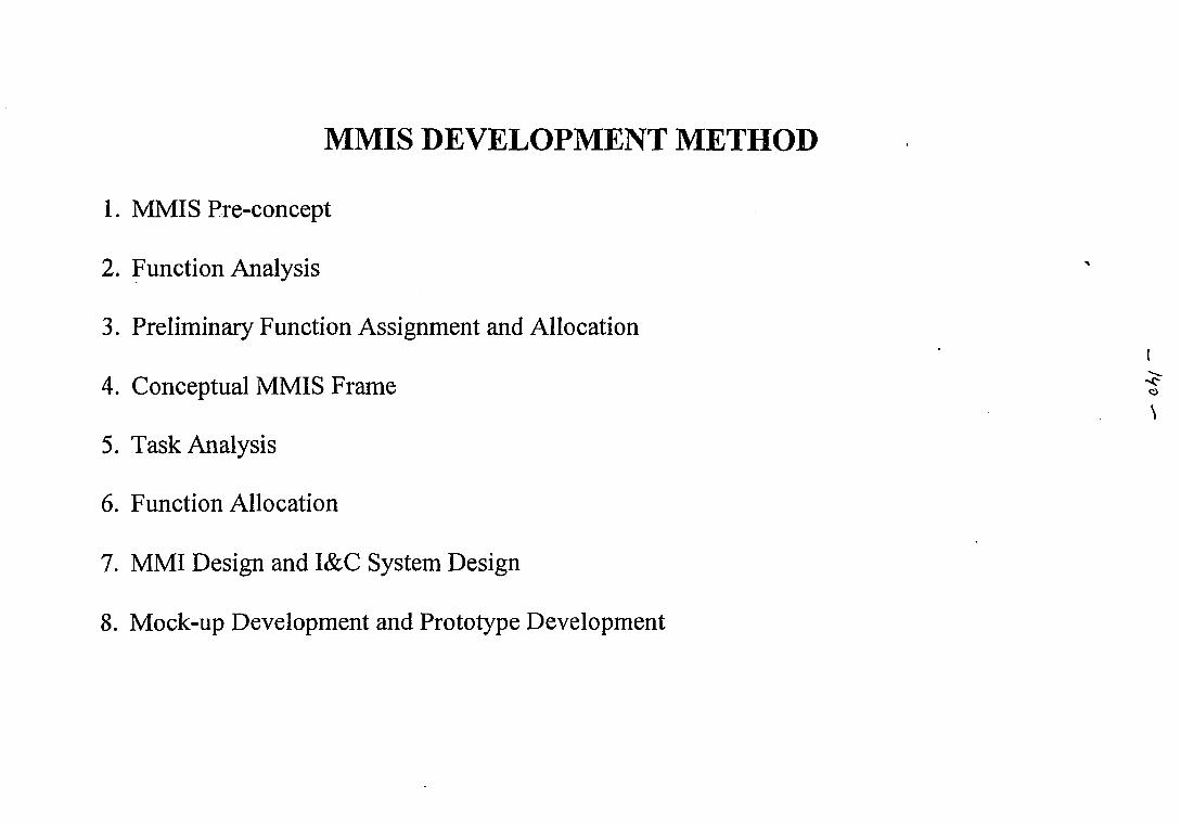
MMIS DEVELOPMENT METHOD
1. MMIS Pre-concept
2. Function Analysis
3. Preliminary Function Assignment and Allocation
4. Conceptual MMIS Frame
5. Task Analysis
6. Function Allocation
7. MMI Design and I&C System Design
8. Mock-up Development and Prototype Development
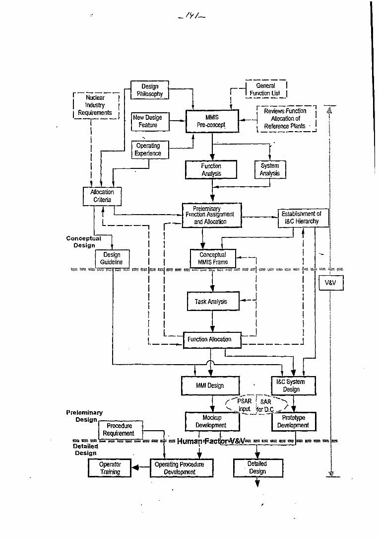
r WnHpar 1
Industry jRequirements i
1
t
DesignPhilosophy
New DesigeFeature
Experience
AllocationCriteria
fL
ConceptualDesign
11
MMISPre-concept
f
FunctionAnalysis
—, i——i
DesignGuideline
•W>: 5:S« * « » yxst ?SE> Sv«: inx tiSS <S8>
i
1
1111
f
PreleminaryFunction Assionment
and Allocation
ConceptualMMIS Frame
5SHS SSS: SM& Ji-^- w* i : *« K « K-;« K<-
j
1 "
PreleminaryDesign
3S3S SS® »8SS
ProcedureRequirement
DetailedDesign
OperatorTraining
Task Analysis
r
Function Allocation
1c\
MMI Design
i f v ^
MockupDevetopment
__j General1 Function List
i~ Reviews FunctioJ Allnnation of
n *
1 Reference Plants •1
5.
!1
SystemAnalysis
1
1rstaWishment ofI&C Hierarchy
f
« SSS SSSj «S¥ tSS sss !«:» KJS •
1
I
•
PSAR | SARInput JforD.I
r
I&C SystemDesign
1 Prototype1 Devetopment
!
•: K!S i * « •«¥.<
v&v
i
1
Operating ProcedureIJevslopment
DetailedDesign •\V
DEVELOPMENT OF NEXT GENERATION REACTOR
1. Main Control Room
2. Information Processing System
3. Safety Indication and Alarm System
4. Plant Protection System . ^
5. ESF Actuation Control System <̂
6. Core Protection Calculator System
7. Process Control System
8. Power Control System
9. Misc. System
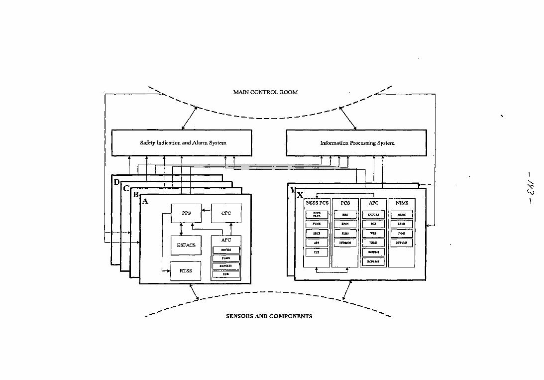
MAIN CONTROL ROOM
Safety Indication and Alarm System Information Processing System
PPS
[ tESFACS
RTSS
CPC
1APC
| EOTMS |
PAM3 |
KCTSS53 I
sot |
PCS APC NIMS
SENSORS AND COMPONENTS
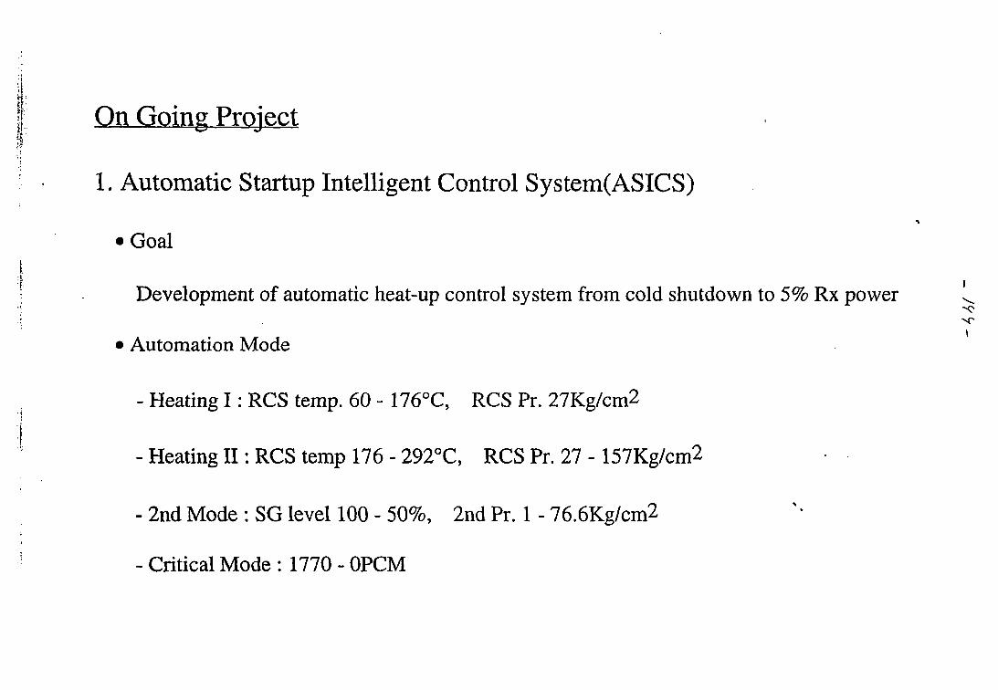
On Going Project
1. Automatic Startup Intelligent Control System(ASICS)
• Goal
Development of automatic heat-up control system from cold shutdown to 5% Rx power
• Automation Mode
- Heating I : RCS temp. 60 - 176°C, RCS Pr. 27Kg/cm2
- Heating II : RCS temp 176 - 292°C, RCS Pr. 27 - 157Kg/cm2
- 2nd Mode : SG level 100 - 50%, 2nd Pr. 1 - 76.6Kg/cm2
- Critical Mode : 1770 - 0PCM
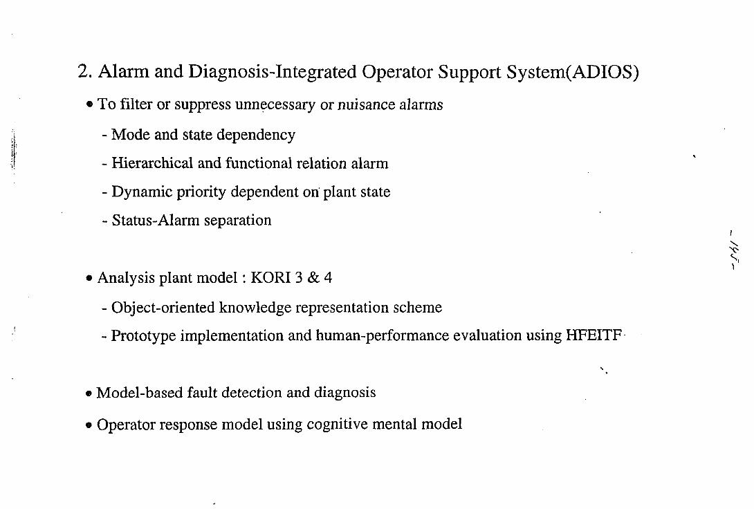
2. Alarm and Diagnosis-Integrated Operator Support System(ADIOS)
• To filter or suppress unnecessary or nuisance alarms
- Mode and state dependency
- Hierarchical and functional relation alarm
- Dynamic priority dependent on plant state
- Status-Alarm separation
• Analysis plant model: KORI 3 & 4
- Object-oriented knowledge representation scheme
- Prototype implementation and human-performance evaluation using HFEITF
s
• Model-based fault detection and diagnosis
• Operator response model using cognitive mental model
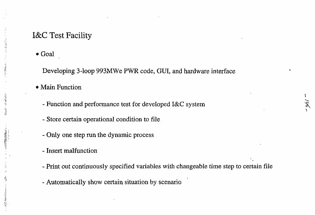
I&C Test Facility
• Goal
Developing 3-loop 993MWe PWR code, GUI, and hardware interface
• Main Function
- Function and performance test for developed I&C system
- Store certain operational condition to file
- Only one step run the dynamic process
- Insert malfunction
- Print out continuously specified variables with changeable time step to certain file
i
- Automatically show certain situation by scenario
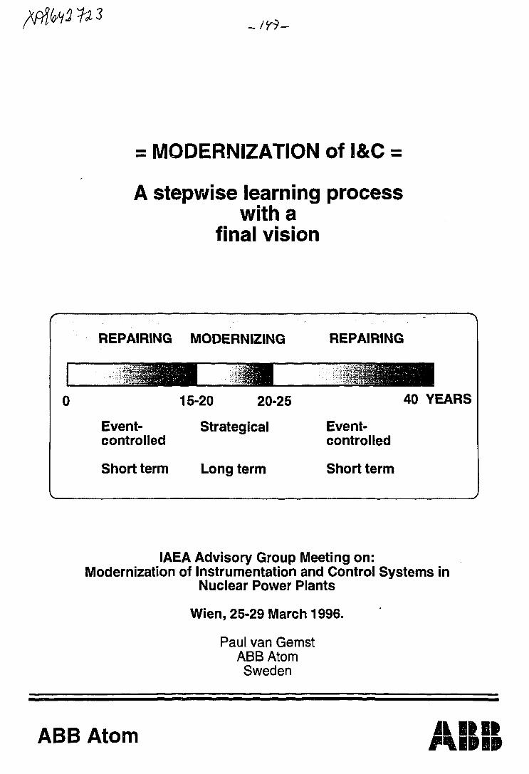
= MODERNIZATION of I&C =
A stepwise learning processwith a
final vision
c
REPAIRING
11191i
Event-controlled
Short term
MODERNIZING
15-20 20-25
Strategical
Long term
REPAIRING
40 YEARS
Event-controlled
Short term
J
IAEA Advisory Group Meeting on:Modernization of Instrumentation and Control Systems in
Nuclear Power Plants
Wien, 25-29 March 1996.
Paul van GemstABB AtomSweden
ABB Atom A IB II
ABB Atom-SC/Paul van Gemst
Summary
In spite of some political signals it is expected that the life time onuclear power plants in the Nordic countries will be as designed for.As the economical life time of the I&C equipment is less than thecorresponding life time of the plant a strategy for modernisation of itmust be developed.
To modernise equipment during ongoing operation of the plant is not onla technical challenge but also a challenge to human relations.It will give a unique chance for the old generation, who built theplants, and the young generation, who have to modernise the plants, tdiscuss common problems and new ideas.
The purpose of this paper is to summarise some important aspects whiccan be included in the content of the planned IAEA book.
Lifetime phases
During the first lifetime phase of the power plant the I&C equipment isrepaired and modified on an "event" controlled way. What I am meaningwith the word "event" is that repairs and modifications are decided andcarried out when component faults or design errors are detected.These activities are carried out on a short term basis.As the equipment became older such short term activities will increaseuntil a moment that some drastically and other methods have to bedecided.
Such decision must be taken before the costs for repairing became sohigh that it is difficult to "free" capital for investments in newequipment.
This is the situation for many nuclear power plants in the Nordiccountries.In order to quarantee the safe, reliable and economical operation of thepower plant strategies for modernisation of I&C equipment are developed,initiated and carried out. Such strategies will often cover a long timeperiod of several, up to, 10 years.
Strategy.
Depending on the age of the plants and the type of technology of the I&Cequipment different types of strategies are developed. A common elementfor all strategies is that modernisation shall be prepared during plantoperation and be carried during the normal planned refuelling outages.The main goal is that modernisation shall not reduce the plantavailability.
The plans include a learning process with a stepwise replacement ofequipment.The most important decision from the start is that all modernisationshall be a logical part of the final I&C integrated configuration afterthe modernisation process during many years.
How this final "vision" can be reached has been the subject fodifferent studies.
It is obvious that two different strategies are possible.
The first one is to replace systems one by one and provide possibilitie
ABB Atom-SC/Paul van Gemst 3
to connect these later into a final integrated I&C system. The advantageis, of course, that systems and the later network can be purchased withthe latest technology in free competition. The disadvantage is that muchsoftware engineering is required to integrate the systems with thenetwork. Solutions for such integration are often unique and notsupported as a standard design.
Another strategy is to establish the infrastructure "network" for theI&C from the beginning and to connect systems stepwise later. Theadvantage is that integration costs are reduced because the structure isan well.proven standard design.The disadvantage is of course that often standard systems must bepurchased from the same manufacturer as for the network. The choice oftechnology is not longer totally free. This option seems to be the mosteconomical one today.
Common for both strategies is that the first modernisation step must beselected with regard to:
the best spin-off for learning of the application andthe operation of new technologythe volume of communication for establishing therequirements for and installation of theinfrastructure
A typical example for this first step is the plant process computer withcontrol room MMI and communication to other computers and to the processI&C.
As a minimum following aspects shall be included in the strategy:
- the final I&C structure "vision"the method for integrationselection of the first steplimitation and restrictionssafety and licensingfunctional upgradingstep by step implementationnew technologyproductsdesign requirements
- project organisationBudgeting
Vision
It is clear that the modernised equipment shall be based on digitaltechnology. The different systems shall be connected with each other bynetworks.Different types of networks shall be available as for:
process control and supervisioncontrol room MMIplant technical and administration servers andcomputers
A example of such an infrastructure is enclosed.
ABB Atom-SC/Paul van Gemst
Limitation and restrictions.
Modernisation of I&C for an existing plant must take care of somelimitations. Such limitations must be defined as a policy in thebeginning of the modernisation process.The limitations can be a result of:
limitation of plant layoutintegration philosophyavailable free spacesexisting process systemsexisting control room and maintenance organisationand staffingavailable time during refuelling outages
- money
Safety and licensing.
The main safety goal is to increase safety by using more modern safetyrequirements. Requirements can be obtained by reading formal criteriaand standards or by executing a PSA (Probabilistic Safety Assessment).However, as the plant was designed for many years ago, it can beproblem to meet all modern requirements.The limitations and restrictions as mentioned before can put limits onthe modernisation of the safety. Deviations between the modernisationgaols and formal modern requirements must be listed, evaluated andagreed upon with the licensing authorities. For some old power plantsin Sweden such deviations against formal requirements are evaluatedwith a PSA (Probabilistic Safety Assessment). The PSA methods can alsosuccessfully be used to identify weak points in the existing design.Another input for increasing safety are the evaluation reports fortransients, incidents or accidents.An important discussion point in the Nordic countries is what type ofsafety standards shall be used. IEEE, which was used for the originaldesign, or the newer IEC? Very often IEEE is selected as the othermechanical and process systems are also following USA criteria andstandards.
Functional upgrading.
The main reason for modernisation is to replace an obsolete equipment.To increase functions is often not foreseen but can identified later.
Typical new functions are:
increasing the degree of automationimproving the operational supportimproving the administration of maintenancereducing manpowerspecialist engineering supportbetter process transient management
A normal input for the decision for upgrading functions is to studyoperational reports or to interview operation and maintenancepersonnel. Interviewing personnel is also a good method to engage theplant personnel as early as possible in a modernisation process.
_ / J 7 -ABB Atocn-SC/Paul van Gemst
Step by step implementation.
As mentioned before a step by step modernisation is required fordifferent reasons.For most of the plants to start with a few stand-alone steps ispreferable to gain experiences for modernisation and to increase thecompetence of the staff. In order to guarantee the learning aspectsformal agreements can be signed between the original builder of theplants and the utilities.Another point is of course that the size of the individualmodernisation has to be limited in order to make it possible to installthem during a normal refuelling outage. An important aspect is toprovide space for new equipment by step by step removal of oldequipment.Modernisation can be carried out for components, systems or integratedI&C systems. An important gaol to let all modifications be a part ofthe final, long term, I&C configuration.
In order to make the step by step approach possible the new equipmentmust communicate with the existing equipment. This must be planned verycarefully. Consequences for the personnel to operate and maintain twotype of technologies at the same time must be clarified.
New technology.
New technology can solve current problems in a better way and in thisway increase the safety and improve the plant availability. It canfurther include the best of the existing equipment. The new equipmenthas also possibilities to include new or improve old functions.
However, a new equipment has new characteristics different from theexisting equipment. Such new characteristics have to be identified andthe influences on safety and operation must be evaluated.
Typical new characteristics for digital equipment are:
Functions are carried sequentially and the load varydepending on the plant situation. There is arisk for overloads during big transients in theplant if the software system is not designedproperly.
Software can be complex and risk for common designerrors are increased. This can increase the volumeof CMF (Common Mode Failures) if counter measures arenot planned or implemented properly.
- Due to the sequential way of working the timeresponse for the new equipment differs from theexisting analogue or relay equipment
- Concentration of many functions in fewer hardwareunits makes it difficult to analyse consequences ofhardware faults. Such faults can influence theoperation of more process systems as before.
Modern equipment includes methods and tools whichare not suitable for nuclear safety systems.Examples are downloading of data and programs andopen communication. Security ("sabotage") can be a
ABB Atocn-SC/Paul van Gemst
problem if such new methods are allowed in safetysystems.
Elder plants are not provided with sufficientgrounding or other measures for reducing electricaland magnetic interferences. Before installation ofmodern equipment this problem has to be studied andsuitable counteractions to be taken. Due to Europeanlaws standard equipment purchased within Europe hasbeen tested for EMC thoroughly.
Products.
As mentioned before the strategy must include a vision of the final andlong term I&C configuration. This is only possible by using off theshelf products with standardised hardware and software communicationmodules.The manufacturer of the products must quarantee a long term support.Special products only for nuclear application cannot be supported in along term.
Using standard products with operating experience will also reducedevelopment costs and delivery times and increase availability ofsystems.
The nuclear application will therefor be designed with standardhardware and software modules from an industrial standard productfamily. Typical nuclear requirements will be designed into the targetsystem by using the standard modules in specified way.
Above mentioned reason is the background for the decision of someutilities in the Nordic countries to base the long term modernisationon products of the same manufacturer.
Design requirements.
Design requirements must be specified early in the modernisationproject. They must be under QA control.
They must include following aspects:
- Reconstruction of the original requirementsAdaptation to new technologyAdaptation to newer safety requirementsIncreasing of operational and maintenancefunctions or supportMethods for coexistence of new and old equipment
- Use of modern methods as for:Human factor engineeringVerification and validationPSA (Probabilistic Safety Analysis)Full scale simulation training andvalidation
FMEA (Failure Mode and Affect analysis)Reliability analysisEnvironmental characteristics, separation,earthquake and other typical nuclearrequirements
Requirements are divided into general requirements valid for the wholeI&C and requirements for standalone systems.
ABB Atom-SC/Paul van Gemst
General requirements will often result in the design of configurations"infrastructures" for:
whole I&C system- the control room complex
auxiliary electrical power system.
A point that has already being identified in current projects is thatnew equipment and new safety rules need other types of power suppliesand will require changes in the electrical power supply system.
Project organisation and budgeting.
Modernising I&C during continuous operation is not easy. It need a wellstructured project and project organisation.Strategies have to be decided and plans to made up for a stepwiseintroduction of new systems. Different types of experts from differentorganisations have to be contracted.
The project must be authorised by and accepted in the wholeorganisation of the utility. Especially the end users within theoperation and maintenance departments must be engaged from thebeginning.
Informal information meetings with regulatory authorities have to beorganised and formal licensing process must be planned and carried out.
Personnel has to be trained on new equipment.
In order to install and commission the new equipment during a shortrefuelling outage it is necessary to prepare for installation alreadyduring the operation of the plant. This must be done withoutjeopardising safety or plant availability.
All these aspects together make it sometimes more difficult tomodernise an existing plant than to build a new one.
By means of informal quotations price levels for equipment has to beestimated and a long term budget must be worked out. This budget isapproved by the management of the plant.
- / • T V -ABB Atom-SC/Paul van Gemst
References:
[1} Lars-Erik HallTVOModernisation of the control and instrumentation in the TVO BWRpower plant.IAEA specialist meeting, Munchen 1995
[2] S Borlin, A BackABB AtomBackfitting a digital class IE systemENC'94Transaction volume 2
[3] A LarydABB AtomOperating experience of software in programmable equipment used inABB Atom nuclear I&C applicationsVTT Symposium 147Helsinki, Finland
Acknowledgement:
I want to thank my colleagues for useful suggestions and comments andespecially following persons:
Einar Strobeck Ringhals SwedenBo Sandin Forsmark SwedenLars-Erik Hall TVO FinlandLars Engdahl ' ABB Atom SwedenPer Balldin ABB Atom SwedenAnders Ericsson ABB Atom Sweden.
MORE
Other aspects which can be part of the new IAEA book are:
Case examples for modernisation of:componentssystemsintegrated I&C
An example for a typical nuclear I&C configuration based onoff-the-shelf products.
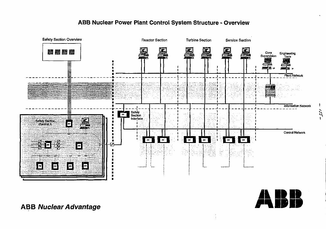
ABB Nuclear Power Plant Control System Structure - Overview
Safety Section Overview Reactor Section Turbine Section Service Section
Core EngineeringSupervision Tools
Plant Network
I
ill
Information Network
Safety Sectionchannel A |FP|
i
-a- --a - a-
| 5 P | . | F P l
0 1
SafetySectionInterface
ii
EIBIControl Network
ABB Nuclear Advantage
JLMI
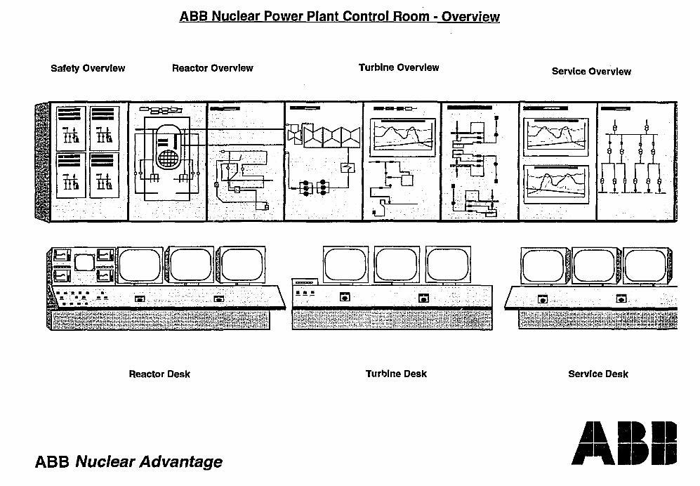
ABB Nuclear Power Plant Control Room - Overview
Safety Overview Reactor Overview Turbine Overview Service Overview
ft
ft
ft
ft
^m fi i
BJr—i O• • • « • • • ' • ' • • .
ffl: \
Reactor Desk Turbine Desk Service Desk
ABB Nuclear Advantage
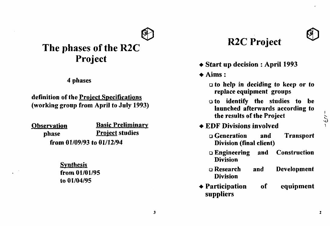
The phases of the R2CProject
4 phases
definition of the Project Specifications(working group from April to July 1993)
Observation Basic Preliminaryphase Project studies
from 01/09/93 to 01/12/94
Synthesisfrom 01/01/95to 01/04/95
R2C Project
• Start up decision : April 1993
• Aims:a to help in deciding to keep or to
replace equipment groupsa to identify the studies to be
launched afterwards according tothe results of the Project
• EDF Divisions involvedQ Generation and Transport
Division (final client)• Engineering and Construction
Division• Research and Development
Division
• Participation of equipmentsuppliers
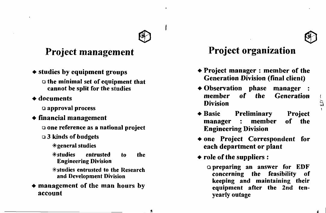
Project management
studies by equipment groups• the minimal set of equipment that
cannot be split for the studies
documents• approval process
financial management• one reference as a national projectQ 3 kinds of budgets
* general studies* studies entrusted to the
Engineering Division* studies entrusted to the Research
and Development Divisionmanagement of the man hours byaccount
Project organization
• Project manager : member of theGeneration Division (final client)
• Observation phase manager :member of the GenerationDivision
• Basic Preliminary Projectmanager : member of theEngineering Division
• one Project Correspondent foreach department or plant
• role of the suppliers :Q preparing an answer for EDF
concerning the feasibility ofkeeping and maintaining theirequipment after the 2nd ten-yearly outage
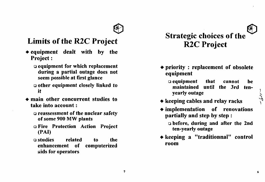
Limits of the R2C Project• equipment dealt with by the
Project:• equipment for which replacement
during a partial outage does notseem possible at first glance
Q other equipment closely linked toit
• main other concurrent studies totake into account:
Q reassessment of the nuclear safetyof some 900 MW plants
a Fire Protection Action Project(PAI)
Q studies related to theenhancement of computerizedaids for operators
Strategic choices of theR2C Project
• priority : replacement of obsoleteequipment
Q equipment that cannot bemaintained until the 3rd ten-yearly outage
• keeping cables and relay racks
• implementation of renovationspartially and step by step :
• before, during and after the 2ndten-yearly outage
• keeping a "traditionnal" controlroom
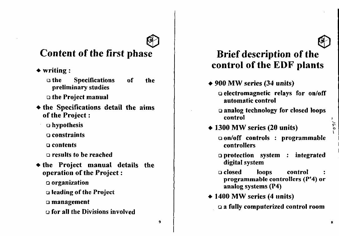
Content of the first phase
• writing :a the Specifications of the
preliminary studies• the Project manual
• the Specifications detail the aimsof the Project:
• hypothesis• constraintsucontents• results to be reached
• the Project manual details theoperation of the Project:
o organization• leading of the ProjectQ managementG for all the Divisions involved
Brief description of thecontrol of the EDF plants
900 MW series (34 units)• electromagnetic relays for on/off
automatic control• analog technology for closed loops
control
1300 MW series (20 units)Q on/off controls : programmable
controllers• protection system : integrated
digital system• closed loops control :
programmable controllers (Pf4) oranalog systems (P4)
1400 MW scries (4 units)• a fully computerized control room
o\
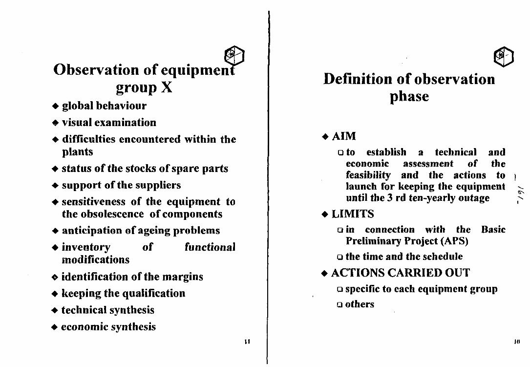
Observation of equipmengroup X
• global behaviour• visual examination
• difficulties encountered within theplants
• status of the stocks of spare parts• support of the suppliers• sensitiveness of the equipment to
the obsolescence of components• anticipation of ageing problems
• inventory of functionalmodifications
• identification of the margins• keeping the qualification• technical synthesis• economic synthesis
11
Definition of observationphase
• AIM• to establish a technical and
economic assessment of thefeasibility and the actions tolaunch for keeping the equipmentuntil the 3 rd ten-yearly outage
• LIMITSa in connection with the Basic
Preliminary Project (APS)• the time and the schedule
• ACTIONS CARRIED OUT• specific to each equipment group• others
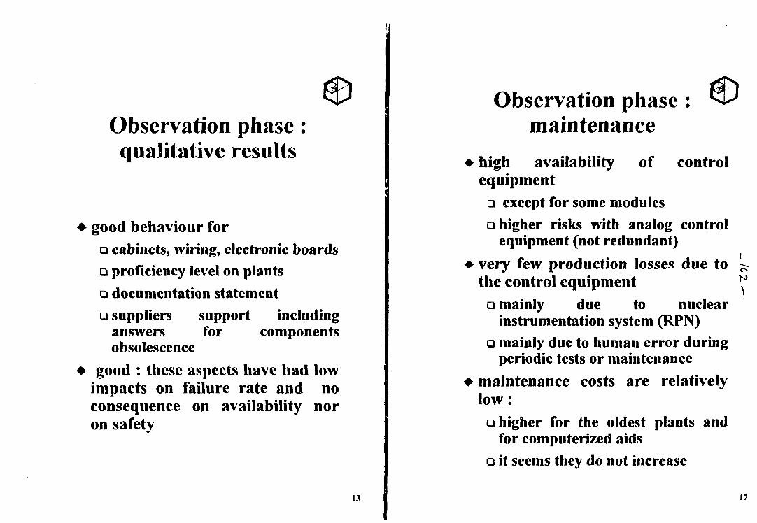
Observation phase :qualitative results
• good behaviour for• cabinets, wiring, electronic boardsQ proficiency level on plantsQ documentation statement• suppliers support including
answers for componentsobsolescence
• good : these aspects have had lowimpacts on failure rate and noconsequence on availability noron safety
13
Observation phase :maintenance
• high availability of controlequipment
• except for some modulesQ higher risks with analog control
equipment (not redundant)
• very few production losses due tothe control equipment
• mainly due to nuclearinstrumentation system (RPN)
• mainly due to human error duringperiodic tests or maintenance
• maintenance costs are relativelylow:
Q higher for the oldest plants andfor computerized aids
a it seems they do not increase
i ;
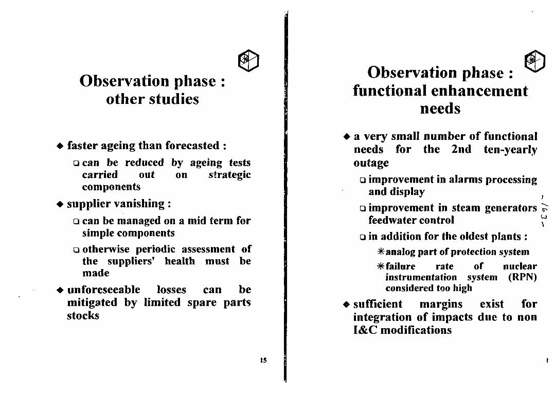
Observation phase :other studies
• faster ageing than forecasted :• can be reduced by ageing tests
carried out on strategiccomponents
• supplier vanishing:
• can be managed on a mid term forsimple components
• otherwise periodic assessment ofthe suppliers' health must bemade
• unforeseeable losses can bemitigated by limited spare partsstocks
15
Observation phase :functional enhancement
needs
a very small number of functionalneeds for the 2nd ten-yearlyoutage
Q improvement in alarms processingand display
a improvement in steam generatorsfeedvvater control
• in addition for the oldest plants :^analog part of protection system* failure rate of nuclear
instrumentation system (RPN)considered too high
sufficient margins exist forintegration of impacts due to nonI&C modifications
to
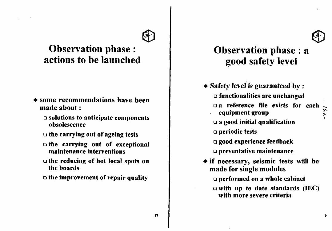
Observation phase :actions to be launched
• some recommendations have beenmade about:
• solutions to anticipate componentsobsolescence
• the carrying out of ageing testsa the carrying out of exceptional
maintenance interventionsQ the reducing of hot local spots on
the boards• the improvement of repair quality
17
Observation phase : agood safety level
• Safety level is guaranteed by :Q functionalities are unchangeda a reference file exists for each
equipment groupQ a good initial qualification• periodic tests• good experience feedbackQ preventative maintenance
• if necessary, seismic tests will bemade for single modules
• performed on a whole cabineta with up to date standards (IEC)
with more severe criteria
i<
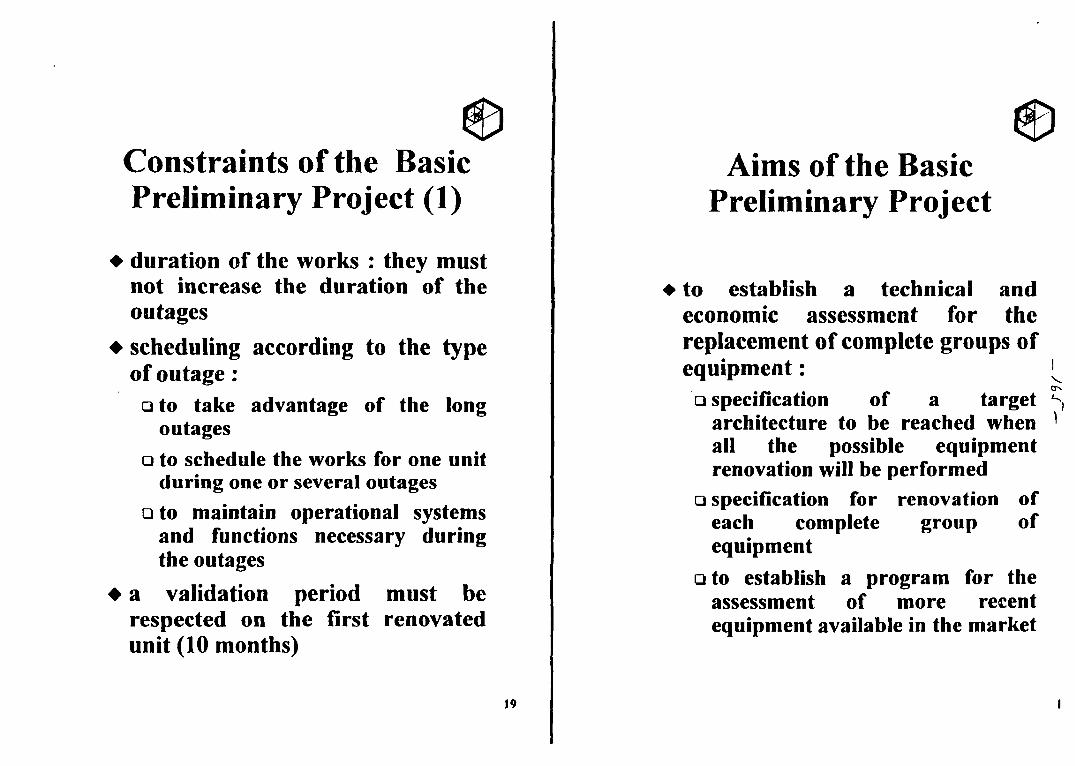
Constraints of the BasicPreliminary Project (1)
• duration of the works : they mustnot increase the duration of theoutages
• scheduling according to the typeof outage :
• to take advantage of the longoutages
• to schedule the works for one unitduring one or several outages
Qto maintain operational systemsand functions necessary duringthe outages
• a validation period must berespected on the first renovatedunit (10 months)
19
Aims of the BasicPreliminary Project
to establish a technical andeconomic assessment for thereplacement of complete groups ofequipment:
a specification of a targetarchitecture to be reached whenall the possible equipmentrenovation will be performed
• specification for renovation ofeach complete group ofequipment
Qto establish a program for theassessment of more recentequipment available in the market
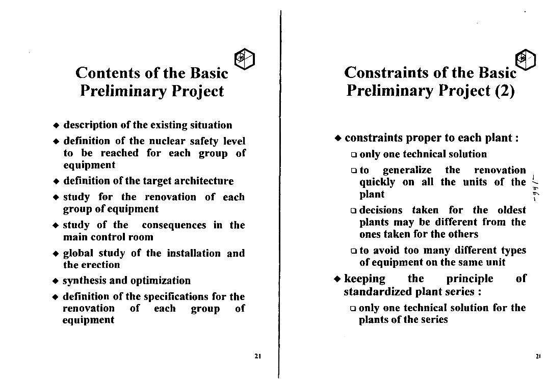
Contents of the BasicPreliminary Project
• description of the existing situation• definition of the nuclear safety level
to be reached for each group ofequipment
• definition of the target architecture• study for the renovation of each
group of equipment• study of the consequences in the
main control room• global study of the installation and
the erection• synthesis and optimization• definition of the specifications for the
renovation of each group ofequipment
21
Constraints of the BasicPreliminary Project (2)
• constraints proper to each plant:• only one technical solution• to generalize the renovation
quickly on all the units of theplant
Q decisions taken for the oldestplants may be different from theones taken for the others
• to avoid too many different typesof equipment on the same unit
• keeping the principle ofstandardized plant series :
• only one technical solution for theplants of the series
21
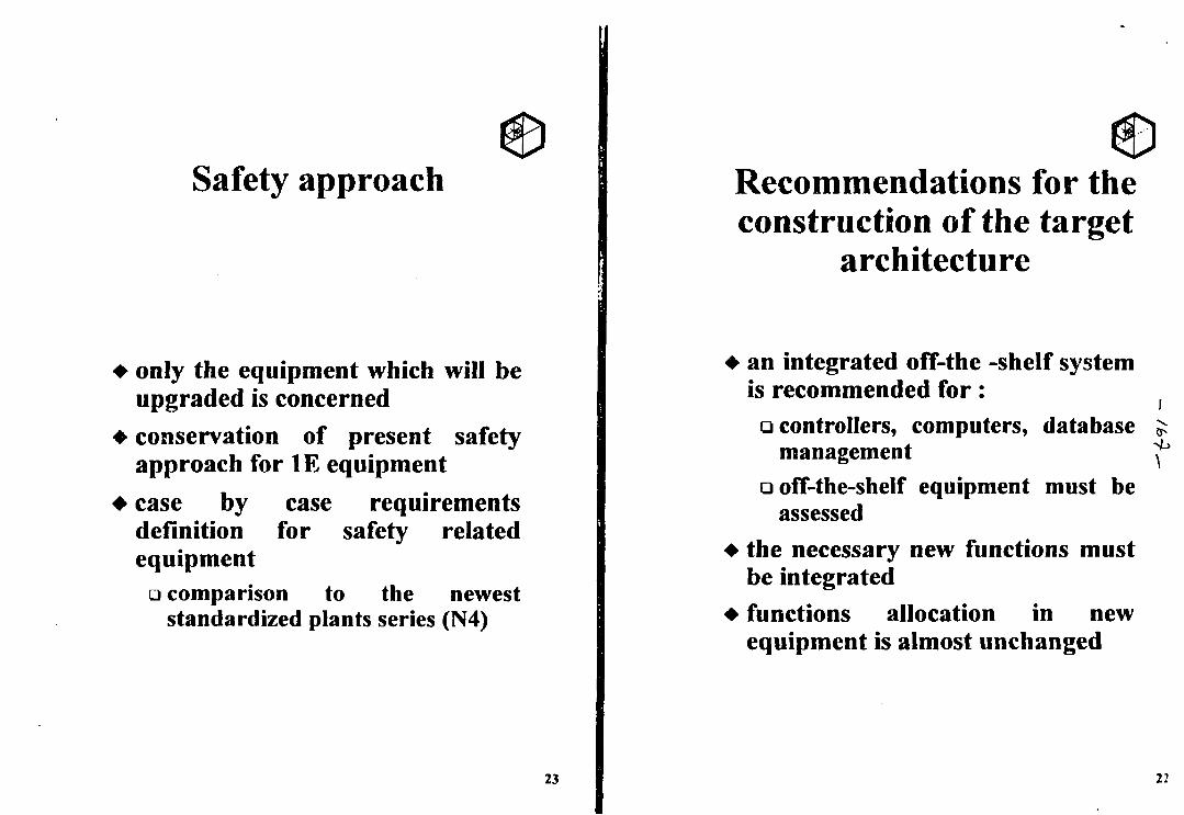
Safety approach
• only the equipment which will beupgraded is concerned
• conservation of present safetyapproach for IE equipment
• case by case requirementsdefinition for safety relatedequipment
LJ comparison to the neweststandardized plants series (N4)
23
Recommendations for theconstruction of the target
architecture
• an integrated off-the -shelf systemis recommended for:• controllers, computers, database ^
management ^• off-the-shelf equipment must be
assessed• the necessary new functions must
be integrated• functions allocation in new
equipment is almost unchanged
22
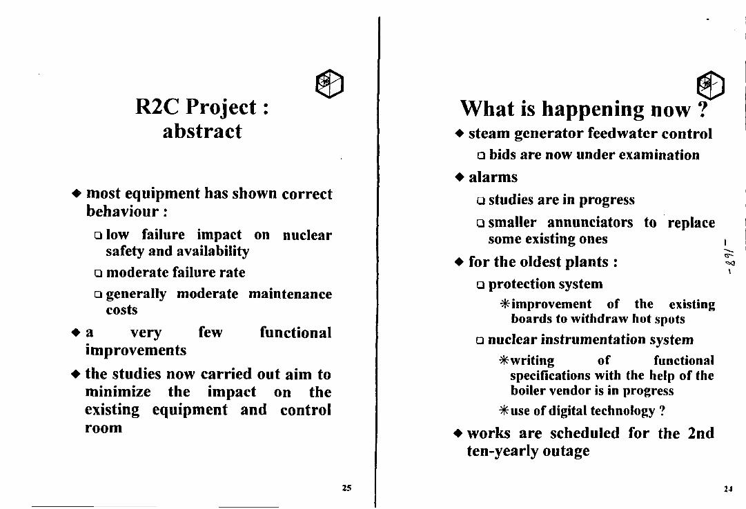
R2C Project:abstract
• most equipment has shown correctbehaviour:• low failure impact on nuclear
safety and availability• moderate failure rateG generally moderate maintenance
costs• a very few functional
improvements
• the studies now carried out aim tominimize the impact on theexisting equipment and controlroom
25
What is happening now ?• steam generator feedwater control
• bids are now under examination• alarms
Q studies are in progressQ smaller annunciators to replace
some existing ones• for the oldest plants :
• protection system^improvement of the existing
boards to withdraw hot spots
• nuclear instrumentation system* writing of functional
specifications with the help of theboiler vendor is in progress
*use of digital technology ?
• works are scheduled for the 2ndten-yearly outage
24
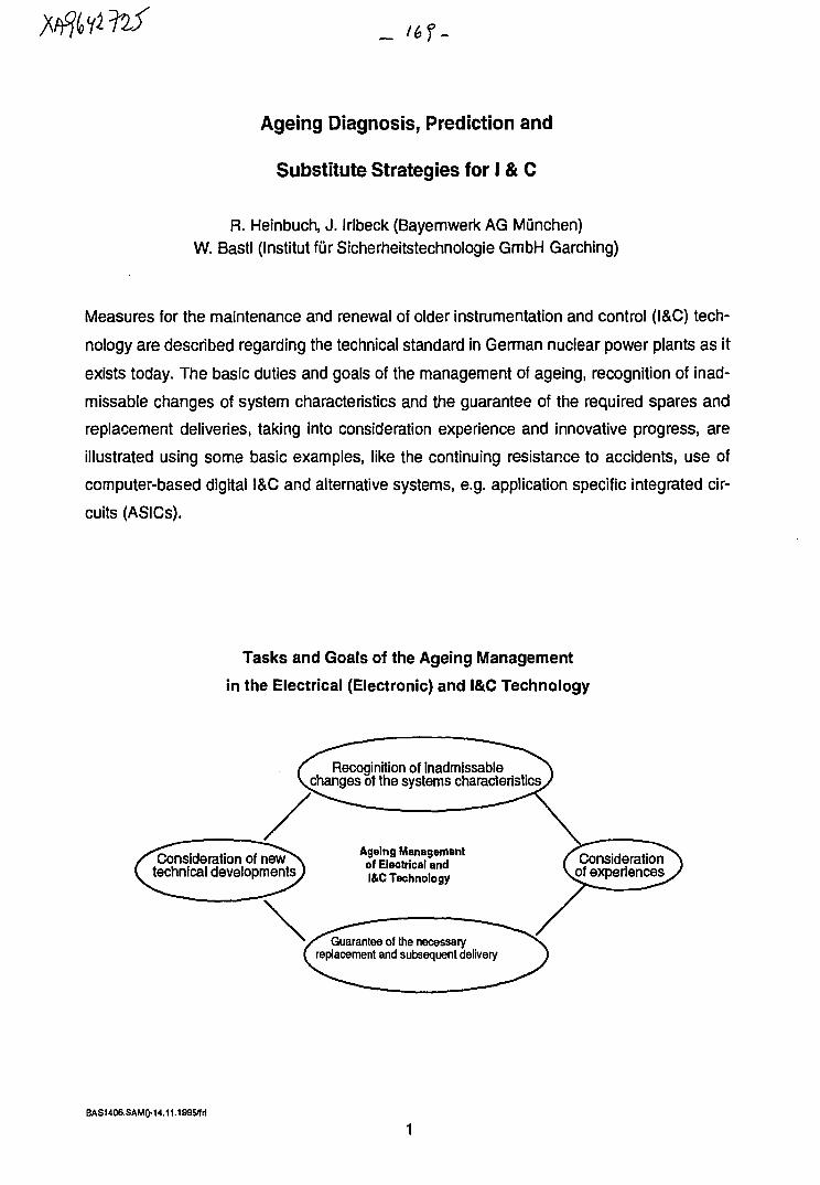
Ageing Diagnosis, Prediction and
Substitute Strategies for I & C
R. Heinbuch, J. Irlbeck (Bayernwerk AG Munchen)W. Bastl (Institut fiirSicherheitstechnologie GmbH Garching)
Measures for the maintenance and renewal of older instrumentation and control (I&C) tech-
nology are described regarding the technical standard in German nuclear power plants as it
exists today. The basic duties and goals of the management of ageing, recognition of inad-
missable changes of system characteristics and the guarantee of the required spares and
replacement deliveries, taking into consideration experience and innovative progress, are
illustrated using some basic examples, like the continuing resistance to accidents, use of
computer-based digital I&C and alternative systems, e.g. application specific integrated cir-
cuits (ASICs).
Tasks and Goals of the Ageing Management
in the Electrical (Electronic) and I&C Technology
Recognition of inadmissablechanges of the systems characteristics
/consideration of new( technical developments
Ageing Managementof Electrical andI&C Technology
Guarantee of the necessaryreplacement and subsequent delivery
Considerationof experiences
BAS1406.SAMO-14.11.199 yfri
1 Introduction
The German nuclear power plants that are in operation today were built in the years from
the mid 60's till the end of the 80's. During this time, several I&C generations were devel-
oped by the industry which are used in the power plants today. With the exception of the
process computer based information system, there are fixed wired electronic systems built
up in discreet semiconductor technology. I&C of todays conventional power plants and
backfittings in the conventional areas of nuclear power plants are principally being realized
in digital I&C technology. In future, this technology will also be favoured by the supplier in-
dustry, so that the traditional I&C systems receive increasingly less supplier support.
The proof of functioning of the operational and safety relevant I&C is ensured by extensive
repetitive tests. With these tests it was assumed until now that the proof for resistance to
accidents, attained at the plant erection within the frame of the type tests with timelapsing
ageing simulation, wouldn't have to be repeated for the remaining lifespan of those particu-
lar tested components. In the last couple of years extensive discussions and investigations
took place, about the period of confidence of the accident resistance proof carried out
within the frame of the type testing. The results of these tasks are recognized in the KTA-
Regulations draft 3706 (13.06.1994). In this paper the consequences drawn for the repeti-
tive proof of the LOCA (loss of coolant accident) proofness of I&C components of the safet
system are discussed.
However, the ageing condition of the systems will not only be measured by whether the de-
mands set at the time of construction are still fulfilled, but also whether today more efficien
and more reliable systems are on hand than those used during plant construction. The ex-
perience gained from the renewal of these systems is described with the aid of concrete ex
amples for enhancing of the man-machine interface and for improving the system
availability. Furthermore, from the demands of the longterm functional upkeep of the ol
I&C technology and the guarantee of subsequent delivery of suitable replacement systems,
basic tasks result for the management of ageing.
B AS U06.SAMO-14.11.1995/1(1
2 Present situation
The production of the I&C technology as used when building the plants has practically
come to a standstill. The supply of spare parts can momentarily only be assured by way of
special productions, reserve of spares, new generation of instruments with similar proper-
ties. These special productions live from a stack of components (transistors, diodes, etc.)
which is not refilled anymore. In our opinion, the availability of the remaining stocks and the
arising costs thereof are not determinable anymore.
Ageing effects are noticeable in the older plants (drift phenomena, electrolyte capacitors).
The failure rates still lie within the normal range. Until now, the maintenance measures
needed for the functional upkeep, could still be executed with reasonable expenditure in
the old technology.
The exchange of the I&C systems will be necessary up to three times during the lifespan of
the power plants. Exchange actions are currently performed. For I&C expansions in the op-
erational and safety relevant areas (requirement class 3), computer based digital I&C sys-
tems are basically being engaged. It is to be expected that an increasing need for suitable
new I&C systems will arise, with which the safe and reliable continued operation of the
power plants can be secured.
2.1 Proof of the functional capability
2.1.1 Recurring tests
The proof of the required functional capabilities and constancy in use of the electrical and
I&C components is performed during manufacture, construction and commencement of op-
eration. The preservation of these characteristics is being proven by repeated testing,
which is carried out either during operation or shutdown of the plant.
These tests require a relatively large personnel effort, if testing has to be manually. So, as
far as possible, automatic testing equipment is used. As a rule computerized testing aids
are used to which high quality requirements are made. Of course, special attention is paid
to the software.
BAS1406.SAMQ-14.11.199S/frl
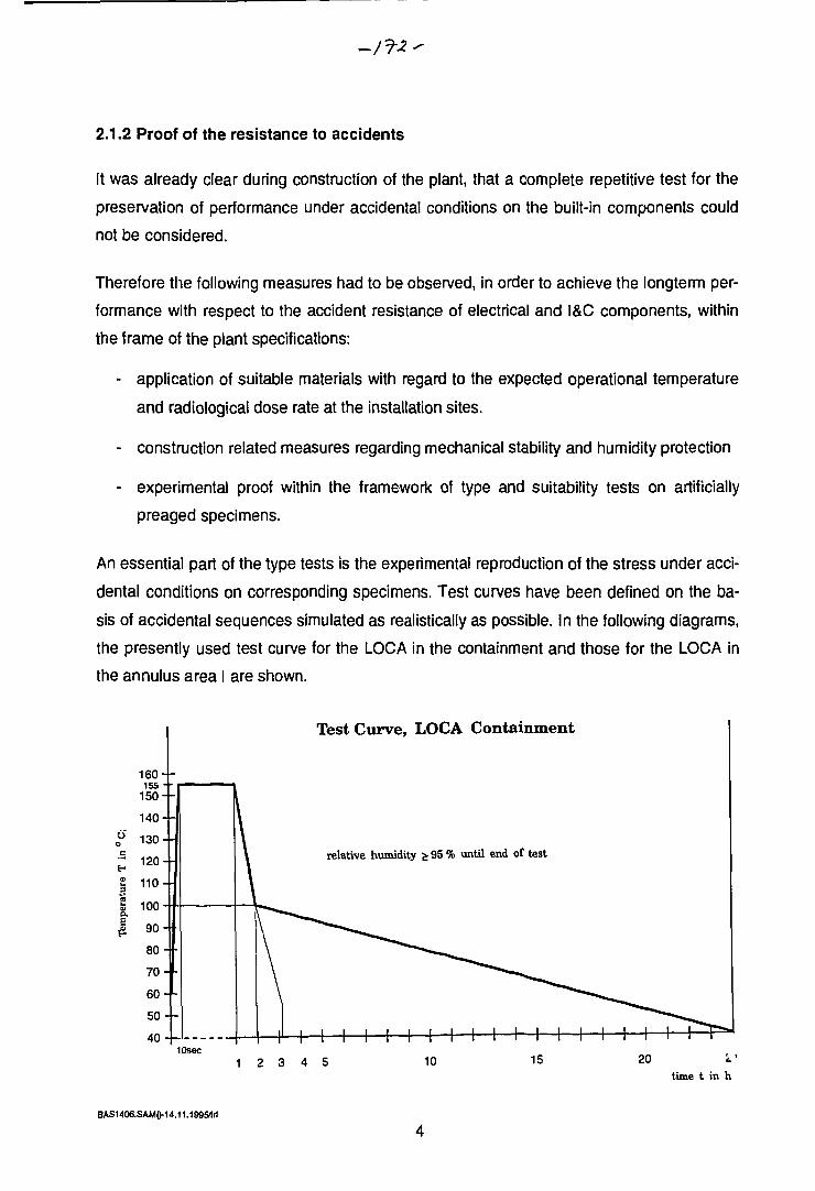
2.1.2 Proof of the resistance to accidents
It was already clear during construction of the plant, that a complete repetitive test for the
preservation of performance under accidental conditions on the built-in components could
not be considered.
Therefore the following measures had to be observed, in order to achieve the longterm per-
formance with respect to the accident resistance of electrical and I&C components, within
the frame of the plant specifications:
- application of suitable materials with regard to the expected operational temperature
and radiological dose rate at the installation sites.
- construction related measures regarding mechanical stability and humidity protection
- experimental proof within the framework of type and suitability tests on artificially
preaged specimens.
An essential part of the type tests is the experimental reproduction of the stress under acci-
dental conditions on corresponding specimens. Test curves have been defined on the ba-
sis of accidental sequences simulated as realistically as possible. In the following diagrams,
the presently used test curve for the LOCA in the containment and those for the LOCA in
the annulus area I are shown.
10sec
Test Curve, LOCA Containment
relative humidity £ 95 % until end of test
1 2 3 4 5 10 15 20time t in h
BAS1406.SAMO-14.11.199 SI ri
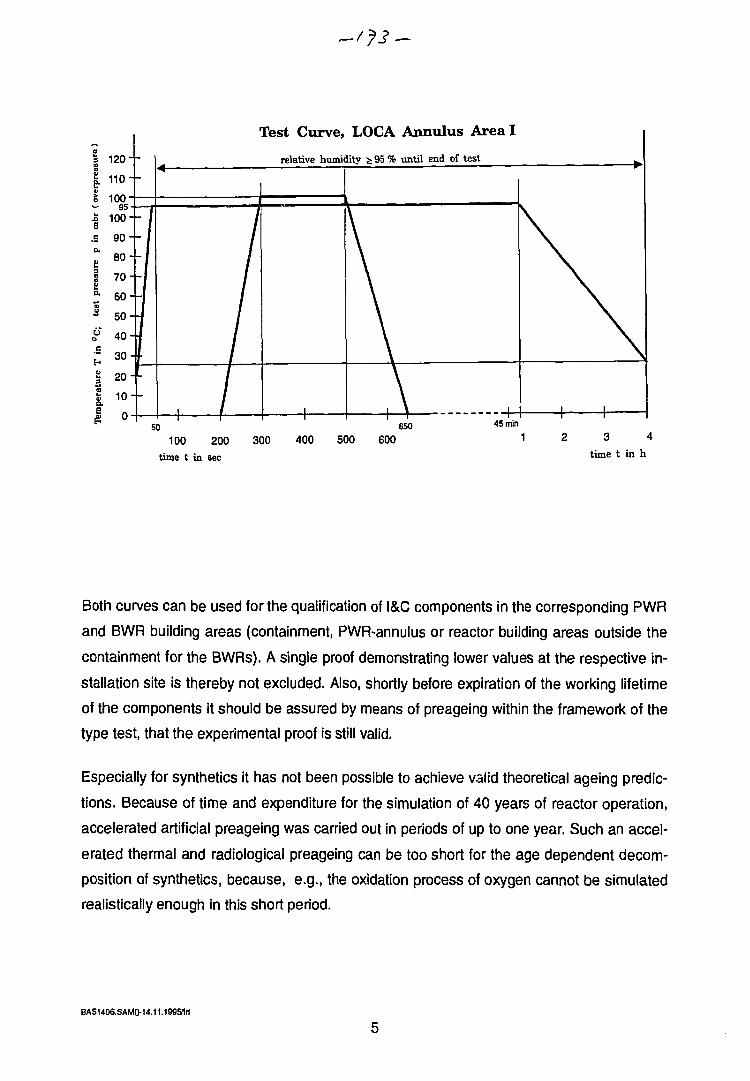
a*
u.a
_C
a«m
§
a.
16"
120-
110"
100"
100-
90-
80-
7 0 -
60-
50-
40-
-
-
r
-130 420-f-10-
0-
r
I-1
////////
Fest Curve, LOCA Annulus Area I
relative humidity ^95% until end of test
1
\\\\\\\\
\-A -H
\\
\\
\\
\\
1 150 650 45min
100 200time t in sec
300 400 500 600 1 3 4time t in h
Both curves can be used for the qualification of I&C components in the corresponding PWR
and BWR building areas (containment, PWR-annulus or reactor building areas outside the
containment for the BWRs). A single proof demonstrating lower values at the respective in-
stallation site is thereby not excluded. Also, shortly before expiration of the working lifetime
of the components it should be assured by means of preageing within the framework of the
type test, that the experimental proof is still valid.
Especially for synthetics it has not been possible to achieve valid theoretical ageing predic-
tions. Because of time and expenditure for the simulation of 40 years of reactor operation,
accelerated artificial preageing was carried out in periods of up to one year. Such an accel-
erated thermal and radiological preageing can be too short for the age dependent decom-
position of synthetics, because, e.g., the oxidation process of oxygen cannot be simulated
realistically enough in this short period.
BAS1406.SAMD-U.11.199S1ri
A reduction of accelerated artificial preageing may become useless if, during or shortly after
completion of the type test, further developed modem instruments are already on the
market.
For all these reasons the continuing resistance to accident conditions of the I&C compo-
nents should be secured during their operation. Prerequisite is a basic accident proof de-
sign in the sense of the abovementioned measures.
2.2 Preservation of the accident resistance
The accident resistance of the concerned electrical and I&C components must be secured
during the entire life cycle of the plant. From todays knowledge, the thermal and radiologi-
cal preageing methods from the type tests do not cover an operating period of 40 years
safely. Hence it needs to be ascertained, if a still sufficient accident resistance is given.
Thereby, the inspection performed after a certain time for the actuators of older plants, was
focused especially to valve positioners, magnetic positioners including the matching cables,
plugs, terminals and containment penetrations. It was discussed that different components
of the older generation within the containment were to be proven through corresponding
special testing to preserve their accidental resistance. But because better and more suit-
able components are available in the meantime, for example motor positioners, magnetic
positioners, terminals and penetrations, these components were exchanged.
The exchange was supported by aspects like:
- future delivery of older equipment only with higher expenditure guaranteed
- rechecking of valve specification and design
- proof deficiencies from the type test, especially for penetrations
For the motors required during a LOCA in the annulus, theoretical proof showed that by the
temporarily rising environmental temperatures in the annulus no undue shortening of the
lifespan of the windings was to be expected.
At the moment the transducers of the oldest generation for the reactor safety instrumenta-
tion, are being exchanged for more suitable ones. The advanced age of the mechanical
gauges and electrolytic condensors were reasons for this exchange.
BAS1406.SAM0-14.11.1995/M
Within the framework of the revision of positioners (8 year period), on-site tests for leaks in
the housing of the switches were performed for accident proof positioners of the next
generation.
On detection of undue leaks, cable connections including grouting were changed. Together
with the rules given in the specification (like changing of seals, oil and lubricants) as well as
the recurring tests regarding the mechanical forces, it has been and is being secured that
these valve positioners retain their accident resistance up to the next revision. From our
point of view, as long as the delivery of the positioners and subparts is secured under rea-
sonable conditions in future, then these can be operated using this procedure for a long
time without ageing problems.
For a particular cable type used in our plant, a R&D program of the manufacturer has come
up with a noticeable radiation dosis effect after a few years of in plant use. Within the
framework of special tests on I&C cables, which are in use near the primary circuit of the
plant, and which were further preaged in order to obtain a representative ageing profile on
the primary circuit, the load limit regarding dose rate was established by the manufacturer.
Cables in locations near loops, which have reached or are reaching their load limit because
of operational radiation dose rates such that they cannot withstand the dose due to a sub-
sequent loss of coolant, have been exchanged for more suitable cables.
Tests on selected 61 pole resin penetrations carried out within a special test using realistic
conditions for a computed accident course (BWR) gave a satisfactory seal tightness. Fur-
ther tests with 4 pole resin penetrations ar planned.
Especially through exchange but also through the theoretical proof, as well as partially per-
formed special tests, also within the framework of the prescribed component revisions, the
preservation of the LOCA stability has been ensured also for the older component
generation.
Therefore, there exists at this time for all component generations considerable confidence
periods. Proof for the preservation of accident stability must be given in time before the ex-
piration of these confidence periods, be it by theoretical proof, special tests, substitute
tests, parts or component exchange or combined procedures. A significant part is played by
the measurement of the stress due to real temperature and radiation at the location of the
component in order to obtain the real ageing. This can be done through subsequent use of,
BAS1406.SAMO-14.11.1995/lrl
e.g., analyn dosimeters and max thermometers over a reactor cycle with a follow-up ex-
trapolation over past and future time spans. Recent measuring results on BWR (penetra-
tions) are available and are being evaluated at the moment.
Further research and development programs for proof procedures have been initiated.
2.3 Research and development programs
Experience so far shows, that accident proof I&C components of the older generation have
mostly been exchanged, also for other reasons like ageing effects and shortcomings in the
type tests. This experience, however, does not contradict that certain electrical and I&C
components can remain in use for periods which lie in the range of the life expectancy of
the whole plant. An exchange of all accident proof cables or large components like motors
is not necessary because of the small accident stress.
For this reason, for equipment which is basically qualified as accident proof it seems ap-
propriate to develop procedures which make possible an in-use control about the preserva-
tion of the accident proofness. In a VGB working group such activities have taken place
since 1988.
Parallel to this utility working team, the completion of KTA 3706 "Recurrent proof of the ac-
cident resistance of electrical and I&C components of the safety system" was forced. Be-
sides the already mentioned possibilities of exchange of components, two further paths are
kept open in this KTA standard for proving the preservation of accident stability, i.e. substi-
tute and special tests.
In the course of the substitute tests, construction parts which have to cope with accidents
should be tested locally by means of relevant procedures like spraytesting, dive-pressure
tests etc.. The execution of spraytesting on terminals has been assured experimentally by
the manufacturer on order of the VGB working group. The associated procedure (VESPA)
is being assessed at the moment by TUV Rheinland. Further substitute tests cited by KTA
are sealing and heating tests.
In the special tests, the relevant steps of type testing have to be repeated. For this, speci-
mens have to be taken from the plant, for example three or six specimens, in order to form
a large enough sample.
BAS1406.SAM0-14.11.1995/frl
8
In both procedures, care has to be taken on how to assure a large enough load precursor,
either by testing in a shorter time span (substitute testing) or by application of additional ar-
tificial ageing.
TUV Nord investigated the ageing and the lifetime of electrical equipment of the safety sys-
tem and the accident instrumentation in nuclear facilities under operational conditions.
Apart from exceptions they observed no ageing relevant changes in the failure behaviour of
the investigated nuclear power plant components. Regarding valve positioners and mag-
nets aged in use, there exist safety margins under accident conditions. Further relevant re-
sults were:
- electronic components have an innovation cycle which, with the exception of a few parts,
is shorter than the residence time
- the basis for assessing the ageing behaviour of accident proof, electrical components
was not enough
It is planned to continue this project with the cooperation of the utilities.
According to KTA 3706, the point in time for the start of the recurring tests of the LOCA
proofness is to be fixed for each nuclear power plant. Test instructions must be set up be-
fore the test begins and they must be approved by independent experts. The testing strate-
gies, relating to component groups which should be put down in the test instructions, are
being worked on by a VGB working group.
The VGB in continuation of his research and development project on cables has given spe-
cific aims to the plant manufacturer.
The setting up of testing strategies is still in the beginning phase. In order to reach mean-
ingful procedures first of all adequate component samples must be established for all
facilities.
B AS1406.S AM0-14.11.199&f rl
3 Strategies for maintenance and renewal of old I&C
To preserve the function of older I&C systems, so far required a reasonable effort for all fa-
cilities in Germany. In spite of not foreseeing a drastic aggrevation for the delivery situation
regarding the old i&C technology, foresight strategies must be developed to ensure the
longterm preservation of I&C performance.
From a current view the following alternatives can be seen for the renewal of the old I&C
systems:
- spare part keeping and special productions for old I&C systems (current practise)
- substitution of old I&C through new digital I&C for operational systems (partially
practised)
- use of new digital I&C for safety systems
- substitution of old I&C by means of functionally equivalent circuitry which is realised in
modern micro electronics (ASICs).
3.1 Spare part keeping and special productions of old I&C
This method is currently being practised especially in the area of safety relevant I&C. The
quality assurance of the manufacturers and the observation of the statistical failure behav-
iour of the old I&C is being intensively supported by common actions of the utilities within
the framework of the VGB (working group "Qualification of electrical and I&C components"
and working group "I&C failure statistics").
In spite of the fact that failure behaviour is currently still normal, and that the delivery o
spares is still assured to a large extent, in the mediumterm one must count on the renewal
of these systems in the old plants.
3.2 Digital safety systems
Digital I&C for the application in safety systems has been developed or is being develope
in several countries. In Germany, Siemens/KWU, with the support of the German utilities,
has developed TELEPERM XS for the longterm exchange of old safety I&C technology
and TELEPERM XP for operational systems.
BASU06.SAMQ-U.11.1995*1
10
An assessment of the TELEPERM XS concept performed by GRS has established its suit-
ability for use in nuclear facilities under highest safety demands.
For the PWR plants GKN1 and KKU, it is planned to replace the rod control and limitation
system. The technical specifications for these systems will be delivered to the customer in
the near future, they are also the basis for the licensing procedure. TELEPERM XS will also
be offered to the high flux research reactor FRM-2 at Garching.
Furthermore, TELEPERM XS will be used for the safety systems in Rovno. It is in the
manufacturing process and installation is presently planned for the end of next year. The
new system has also been offered to PAKS in Hungary.
Presently, type-testing of the system components is being performed. It will be completed
by the end of this year. For these particular tests, the basic requirements for traditional sys-
tems (as laid down in the KTA rules) were followed. According to these rules, there are:
- theoretical checks (e.g. regarding functional description, specification, load)
- practical checks (e.g. regarding functionality, electromagnetic compatibility, environ-
mental conditions).
In analogy to these traditional rules, type-testing has been also applied to the new digital
system. This was possible because
- the system (regardless of its specific application) consists of approximately the same
hard- and software components
- the system applies re-usable software components (configurable and parameterised ac-
cording to plant specific needs)
- hard- and software interfaces can be uniquely and completely described.
For software components, the following analyses have been performed:
- assessment of the development process and its measures for quality assurance
- trace of functions from requirements definitions via software specification, design, imple-
mentation to the code by desk inspection and static analysis
- verification of software interfaces
BAS1406.SAM0-14.11.1995/lrl
11
- conformity with standards, mainly I EC 880
- conformity with project internal guidelines
- assessment of failure and error analysis
Finally, a system type testing is performed to check the typical system properties:
- correctness of operational behaviour
• correct functional behaviour
• no feedback of fuctions with respect to other functions
• temporal behaviour
• deterministic behaviour of the system (reproducible results)
• ability to be assessed, maintained, diagnosed
- tolerable stress and failure behaviour
• failure and error tolerance
• .ndependent behaviour of the I&C system from the technical process
(resistance to input data overload)
3.3 Renewal of old safety relevant instrumentation and control by copy of functionequivalent circuits (ASICs)
The use of ASICs could be another solution for the replacement of old I&C. The develop-
ment of micro-electronics has led to revolutionary changes in the production of electronic
systems. This means in micro-electronics, a large amount of circuits can be built up mono-
lithically (on the silicium basis), in contrast to old I&C, where the single parts (transistors, di-
odes, resistors, condensors) are put onto printed circuit boards.
These developments, which worldwide are used in great numbers, open up a new perspec-
tive for the renewal and extension of old instrumentation and control systems. In this new
technology of micro-electronics, the switching circuits of the old I&C are copied exactly, i.e.
a new integrated circuit "made to measure" is produced.
BASU06.SAMO-14.11.1995/fri
12
The application of ASICs offers the following basic perspectives:
Safety
- the user-proven fixed switching structures remain
- parallel signal processing
- optimal protection against unnoticed changes
- high degree of integration (therefore fewer contacts)
- design and testing tools proven in mass fabrication
- software problems reduced because only basic procedures of automation theory is be-
ing used during design.
Functionality
- all required analog and binary signal functions can be realized
- the interface to the computer can be directly intergrated
- the test logic can be integrated directly onto the chip
- a high function density and consequently a small volume can be obtained
Compatibility/Flexibility
- pin-compatible assemblies can be realized
- the required flexibility for the protection function during the planning can be ensured
through design tools
At the moment, the VGB Working Group "I&C in NPPs" is testing the possibility of applying
ASICs to replace old instrumentation and control systems. The applicability is being tested
in a pilot utilization. It is expected that qualification requires less effort in relation to software
solutions.
BAS1406.SAM0-U.111995/W
13
4 Improvement of performance through the new instrumentation and
control technology
A system can be out of date in spite of it still fulfilling the originally specified properties. This
is especially true for areas where today much more powerful systems are available and an
improvement of plant availability or plant safety can be achieved.
The following measures (already taken in several German NPPs) can serve as examples
for such improvements:
- the exchange or expansion of plant computers are realized in most plants which are
older than 10 years. The marked aims of these measures are
• improvement of the man-machine interface
• improvement of plant disturbance diagnosis
• expansion of the extent of information
- renewal of the refuelling platform with the aim of
• improving the functionality and the man-machine interface
- renewal of the turbine I&C with the aim of
• improving the availability and the man-machine interface.
5 Summary
The main aims of the tasks for the ageing management in the electrical and instrumentation
and control technology are in the longterm preservation of function while considering tech-
nical development, experience and the guarantee of relevant continuing deliveries.
The functionality is proven by means of repetitive testing. A special problem is the proof for
accident resistance. In extended research and development programs, solutions have been
achieved which have been taken up in the KTA rule 3706.
For the longterm preservation of the function of instrumentation and control, strategies fo
the replacement of old I&C systems are required. The tendency is to replace old I&C
BAS14O6.SAM0-14.11.1995/frt
14
technology in the area of process instrumentation and control and safety relevant instru-
mentation and control by computer-based systems.
The new digital safety instrumentation and control technology requires, like any computer
based system, a high degree of formality to describe the process relevant demands. When
defining these demands, experience and latest developments can be used for
improvements.
On the other hand the establishment of the formal descriptions and their assessment re-
quire a high effort. Therefore further alternatives for the replacement of old instrumentation
and control technology is being searched for, where the development of the new system is
based on the proven circuit design of the old I&C. In this context ASICs appears to provide
promising solutions.
The use of the new I&C technology contributes today in essential areas of nuclear power
plant instrumentation and control to the improvement of performance, e.g. with regard to
the man-machine interface and the diagnostic abilities.
BAS1406.SAMO-U.11.199S/frl
15

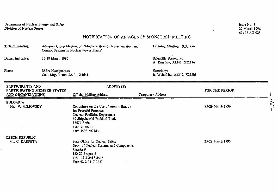
Department of Nuclear Energy and SafetyDivision of Nuclear Power
Title of meeting:
Dates, inclusive:
Place:
NOTIFICATION OF AN AGENCY SPONSORED MEETING
Opening Meeting: 9:30 a.m.Advisory Group Meeting on "Modernization of Instrumentation andControl Systems in Nuclear Power Plants"
25-29 March 1996
IAEA HeadquartersC07, Mtg. Room No. II, X4641
Scientific Secretary:A. Kossilov, A2543, X22796
Secretary:R. Wehofsitz, A2549, X22801
Issue No. 329 March 1996621-I2-AG-928
PARTICIPANTS ANDPARTICIPATING MEMBER STATESAND ORGANIZATIONS
ADDRESSES
Official Mailing AddressFOR THE PERIOD
Temporary Address
BULGARIAMr. V. MILIOVSKY
CZECH REPUBLICMr. C. KARPETA
Committee on the Use of Atomic Energyfor Peaceful PurposesNuclear Facilities Department69 Shipchenski Prokhod Blvd.12574 SofiaTel.: 70 05 14Fax: 3592 702143
State Office for Nuclear SafetyDept. of Nuclear Systems and ComponentsSlezska 9120 29 Prague 2Tel.: 42 2 2417 2445Fax: 42 2 2417 2627
25-29 March 1996
25-29 March 1996
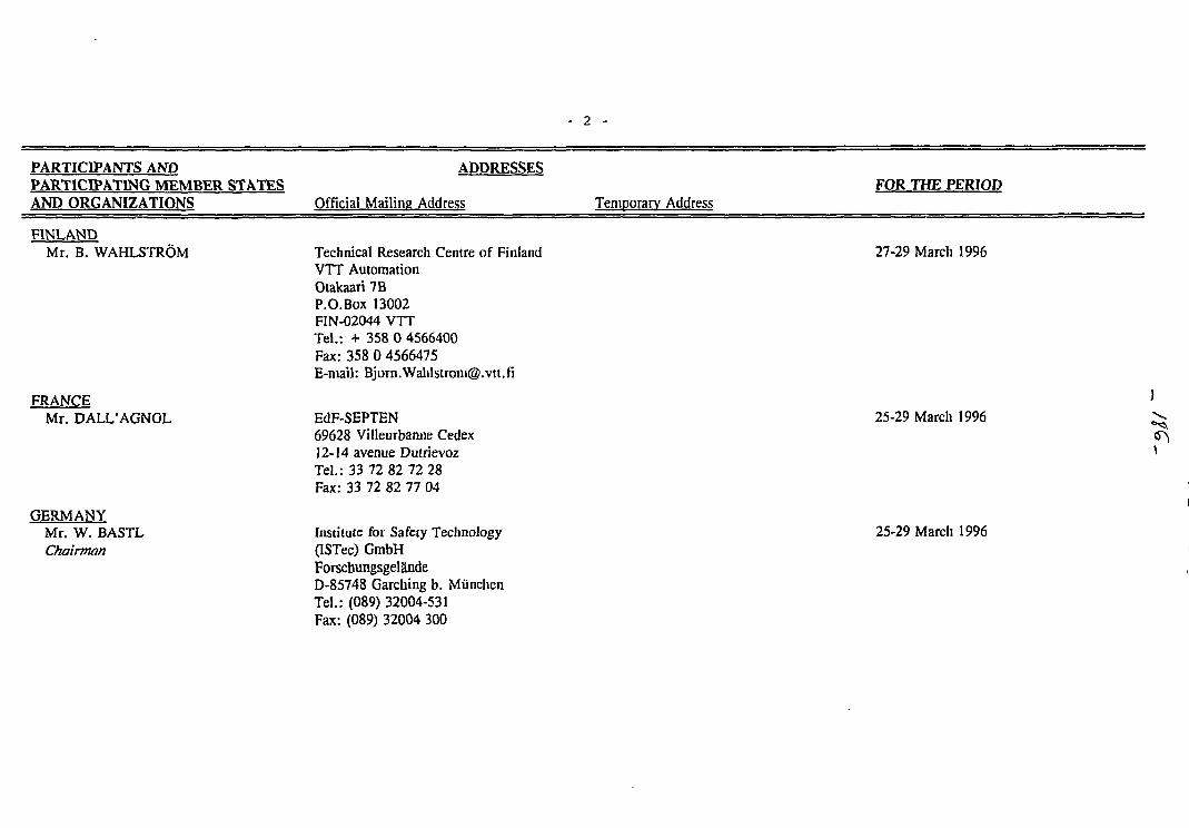
- 2 -
PARTICIPANTS ANDPARTICIPATING MEMBER STATESAND ORGANIZATIONS
ADDRESSES
Official Mailing AddressFOR THE PERIOD
Temporary Address
FINLANDMr. B. WAHLSTROM
FRANCEMr. DALL'AGNOL
GERMANYMr. W. BASTLChairman
Technical Research Centre of FinlandVTT AutomationOtakaari 7BP.O.Box 13002FIN-02044 VTTTel.: + 358 0 4566400Fax: 358 0 4566475E-mail: [email protected]
EdF-SEPTEN69628 Villeurbanne Cedex12-14 avenue DutrievozTel.: 33 72 82 72 28Fax: 33 72 82 77 04
Institute for Safety Technology(ISTec) GmbHForschungsgelandeD-85748 Garching b. MiinchenTel.: (089) 32004-531Fax: (089) 32004 300
27-29 March 1996
25-29 March 1996
25-29 March 1996
- 3 -
PARTICIPANTS ANDPARTICIPATING MEMBER STATESAND ORGANIZATIONS
ADDRESSES
Official Mailing AddressFOR THE PERIOD
Temporary Address
HUNGARYMr. Z. TOTH
KOREA. REP. OFMr. Chang-Hwoi KIM
Mr. In-Soo KOO
RUSSIAN FEDERATIONMr. A.G. CHUDIN(Observer)
Head of Process Computer DepartmentPaks Nuclear Power PlantPostfach 717031 PaksTel.: (36)75 31 85 47Fax: 36 1 553 894E-mail: [email protected]
KAERIP.O.Box 105Yousong, Taejon 305-600Tel.:+ 42-868-2927Fax: + 42-868-8357E-mail: [email protected]
KAERIP.O.Box 105Yusong, Taejon 305-600Tel.: + 42-868-2905Fax: + 42 861 1388E-mail: [email protected]
Ministry for Atomic EnergyStaromonetny 26109180 MoscowTel.: (095) 239 27 95Fax: (095) 233 30 53
25-29 March 1996
25-29 March 1996
25-29 March 1996
25-29 March 1996
- 4 -
PARTICIPANTS ANDPARTICIPATING MEMBER STATESAND ORGANIZATIONS
ADDRESSES
Official Mailing AddressFOR THE PERIOD
Temporary Address
RUSSIAN FEDERATION fcont.)Mr. A. POBEDONOSTSEV
SLOVAK REPUBLICMr. J. DOLEZAL(Observer)
Mr. V. HORVATH(Observer)
Mr. S. U§KERT(Observer)
SPAINMr. J.A. ARBIZA BERREGUI
OKB Mechanical Engineering603603 Nizhny NovgorodByrnakovsky proezd, 15Tel.: (8312) 418902Fax: (8312)418772
NPP Mochovce935 39 MochovceTel.: 0042-813-36-3994Fax: 0042-813-391
Mochovce NPP93539 MochovceTel.: 0042-813-36-3992Fax: 0042-813-391-128
Mochovce NPP935 39 MochovceTel.: 0042-813-36-3603Fax: 0042-813-391 128
INITECGran Via Carlos 111-124-3°08034 3arcelonaTel.: 34-3-2050862Fax: 34-3-2054908
25-29 March 1996
25-29 March 1996
25-29 March 1996
25-29 March 1996
25-29 March 1996
- 5 -
PARTICIPANTS ANDPARTICIPATING MEMBER STATESAND ORGANIZATIONS
ADDRESSES
Official Mailing AddressFOR THE PERIOD
Temporary Address
SWEDENMr. P. van GEMST
U.K.Mr. R. CLARKE(Observer)
ABB Atom ABNuclear Services DivisionS-721 63 VasterasTel.: 46 (0) 347035Fax: 46 (0)347318E-mail: [email protected]
Nuclear Electric pic.Barnett WayBamwoodGlochester GL4 7RSTel.: (1452) 653177Fax: (1452) 652 600
25-29 March 1996
25-29 March 1996
Mr. N. WALL
UKRAINEMr. M.A. YASTREBENETSKY
Nuclear Installations InspectorateSt. Peters HouseStanley PrecinctBootle, Merseyside L20 3LZTel.: 0151 951 3193Fax: 0151 922 5980,
0151 951 3942
Ukrainian Committee of Nuclear andRadiation SafetyScientific Technical Center, I&C Dep.Artema str., 17Kharkov 310078Tel. + fax: 380(572)471700
25-29 March 1996
25-29 March 1996
- 6 -
PARTICIPANTS ANDPARTICIPATING MEMBER STATESAND ORGANIZATIONS
ADDRESSES
Official Mailing AddressFOR THE PERIOD
Temporary Address
U.S.A.Mr. J. NASER Electric Power Research Institute
Nuclear Power Division3412 Hillview AvenueP.O.Box 1041294303-0813 Palo AltoTel.: (415) 855-2107Fax: (415) 855-2774E-mail: [email protected]
Hotel Pension EliteWipplingerstr. 32A-1010 ViennaTel.: 533 25 18-0Fax: 535 57 53
25-29 March 1996
I.A.E.A.Mr. A. KOSSILOVScientific Secretary
Division of Nuclear PowerReactor Engineering SectionP.O.Box 100Wagramerstrasse 5A-1400 ViennaRoom No. A2543Tel.: + 43 1 2060 22796Fax: + 43 1 2060 7E-mail: Kossilov@nepol .iaea.or.at
PARTICIPANTS ANDPARTICIPATING MEMBER STATESAND ORGANIZATIONS
ADDRESSES
Official Mailing AddressFOR THE PERIOD
Temporary Address
I.A.E.A. (cont.)Mr. M. DUSIC Division of Nuclear Installation Safety
Safety AssessmentP.O.Box 100Wagramerstrasse 5A-1400 ViennaRoom No. B0872Tel.: + 43 i 2060 22522Fax: + 43 1 2060 7E-mail: [email protected]
c:\wpwin\kossdocs\ag928.ntf

![Business Rule Inclusion and Legacy Modernization through ...binary instrumentation).We choose in this paper dynamic binary instrumentation [9, 10, 11] for obvious reason because they](https://img.pdfslide.net/doc/110x75/5e7936e5b1935918780cbb25/business-rule-inclusion-and-legacy-modernization-through-binary-instrumentationwe.jpg)