Embed Size (px)
Citation preview
1 © 2015 ANSYS, Inc. February 27, 2015
16.0 Release
Workshop 11.1 Meshing Evaluation
Introduction to ANSYS Mechanical
2 © 2015 ANSYS, Inc. February 27, 2015
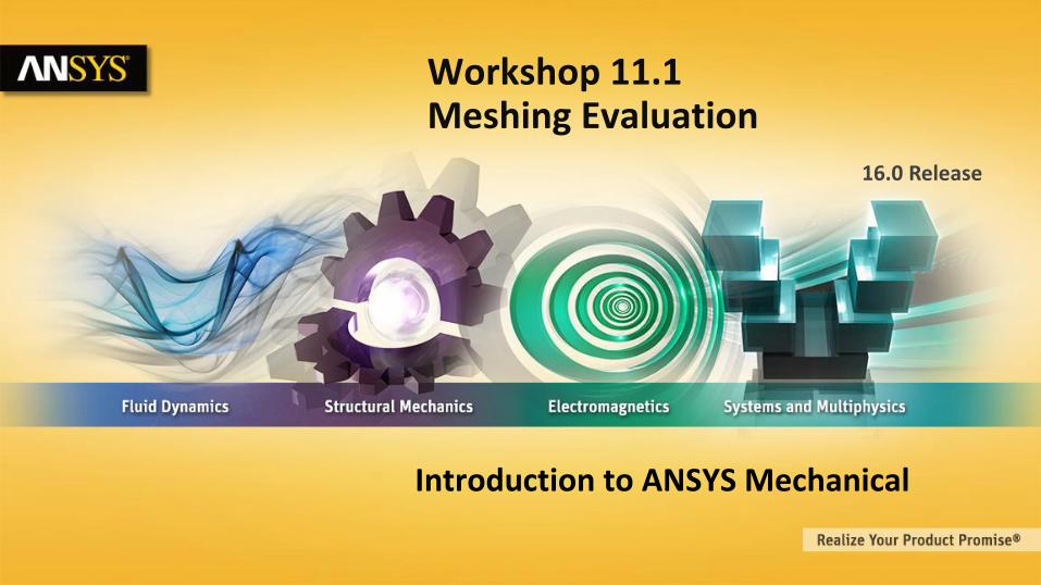
Goals In this workshop an arm from a mechanism will be solved using several different meshes for comparison.
Our goal is to explore how meshing changes can have dramatic effects on the quality of the results obtained.
3 © 2015 ANSYS, Inc. February 27, 2015
Assumptions
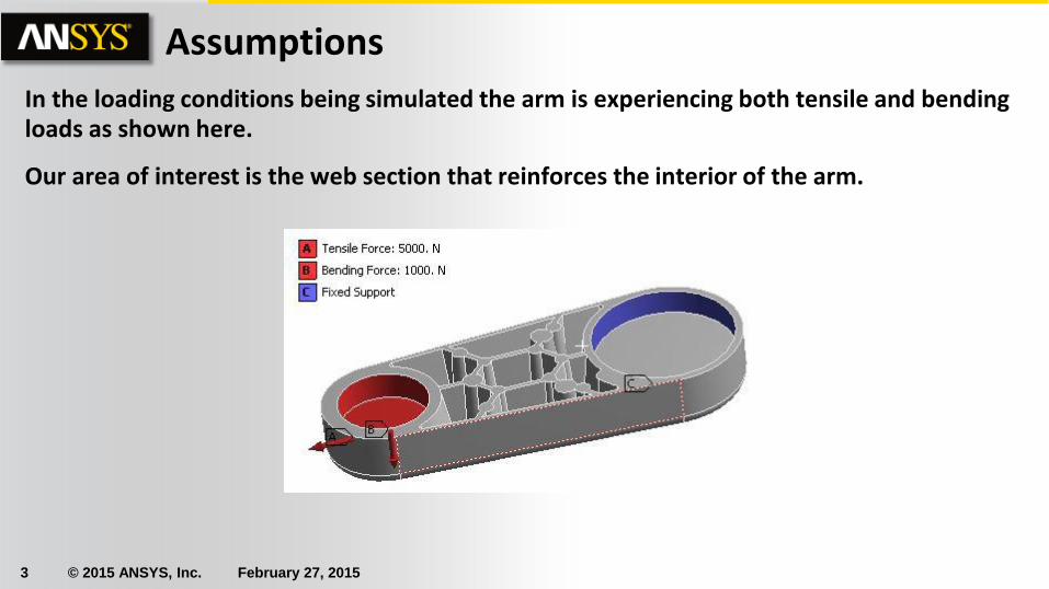
In the loading conditions being simulated the arm is experiencing both tensile and bending loads as shown here.
Our area of interest is the web section that reinforces the interior of the arm.
4 © 2015 ANSYS, Inc. February 27, 2015
Project Schematic
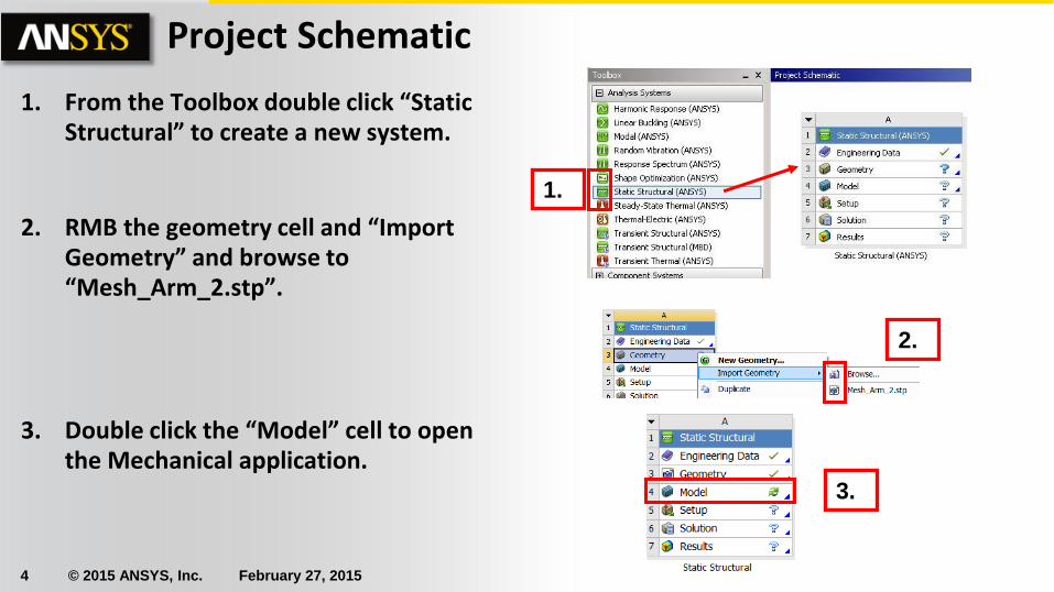
1. From the Toolbox double click “Static Structural” to create a new system.
2. RMB the geometry cell and “Import Geometry” and browse to “Mesh_Arm_2.stp”.
3. Double click the “Model” cell to open the Mechanical application.
1.
2.
3.
5 © 2015 ANSYS, Inc. February 27, 2015
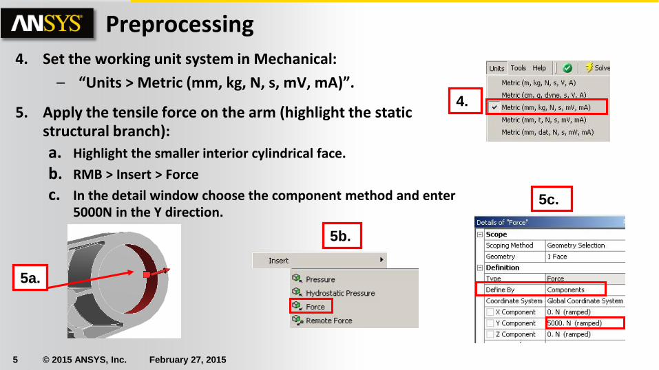
Preprocessing 4. Set the working unit system in Mechanical:
– “Units > Metric (mm, kg, N, s, mV, mA)”.
5. Apply the tensile force on the arm (highlight the static structural branch):
a. Highlight the smaller interior cylindrical face.
b. RMB > Insert > Force
c. In the detail window choose the component method and enter 5000N in the Y direction.
5a.
5b.
4.
5c.
6 © 2015 ANSYS, Inc. February 27, 2015
. . . Preprocessing
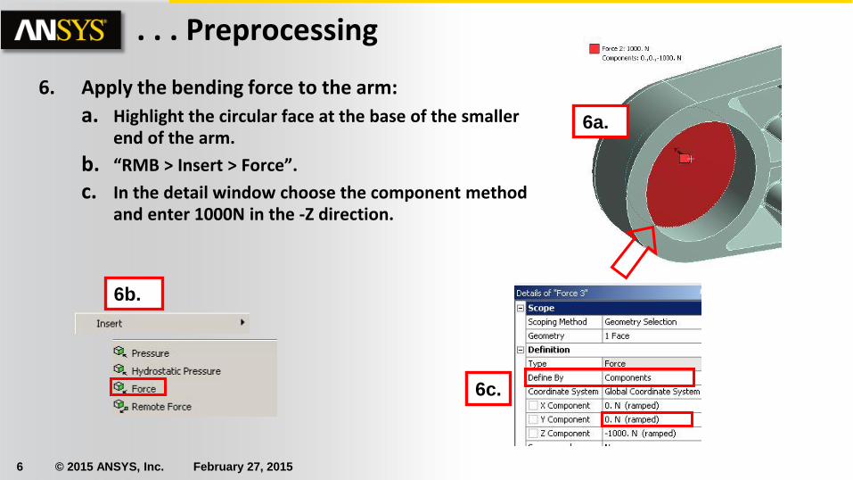
6. Apply the bending force to the arm:
a. Highlight the circular face at the base of the smaller end of the arm.
b. “RMB > Insert > Force”.
c. In the detail window choose the component method and enter 1000N in the -Z direction.
6c.
6b.
6a.
7 © 2015 ANSYS, Inc. February 27, 2015
. . . Preprocessing
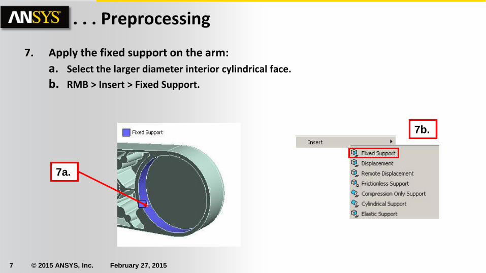
7. Apply the fixed support on the arm:
a. Select the larger diameter interior cylindrical face.
b. RMB > Insert > Fixed Support.
7b.
7a.
8 © 2015 ANSYS, Inc. February 27, 2015
Meshing
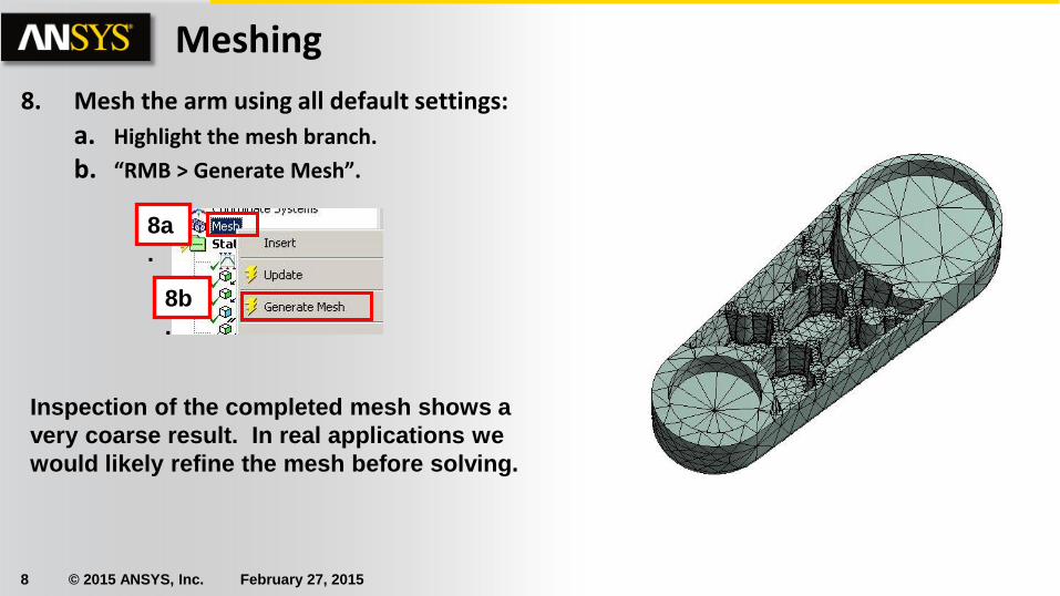
8. Mesh the arm using all default settings:
a. Highlight the mesh branch.
b. “RMB > Generate Mesh”.
Inspection of the completed mesh shows a
very coarse result. In real applications we
would likely refine the mesh before solving.
8b
.
8a
.
9 © 2015 ANSYS, Inc. February 27, 2015
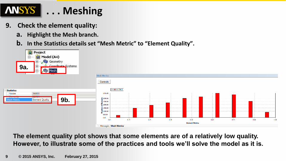
. . . Meshing 9. Check the element quality:
a. Highlight the Mesh branch.
b. In the Statistics details set “Mesh Metric” to “Element Quality”.
9a.
9b.
The element quality plot shows that some elements are of a relatively low quality.
However, to illustrate some of the practices and tools we’ll solve the model as it is.
10 © 2015 ANSYS, Inc. February 27, 2015
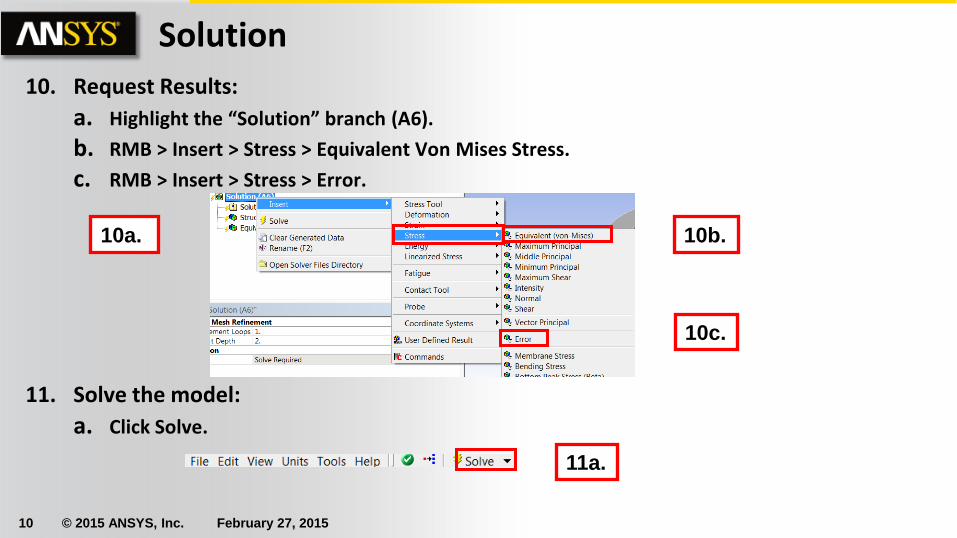
10. Request Results:
a. Highlight the “Solution” branch (A6).
b. RMB > Insert > Stress > Equivalent Von Mises Stress.
c. RMB > Insert > Stress > Error.
11. Solve the model:
a. Click Solve.
Solution
10a. 10b.
10c.
11a.
11 © 2015 ANSYS, Inc. February 27, 2015
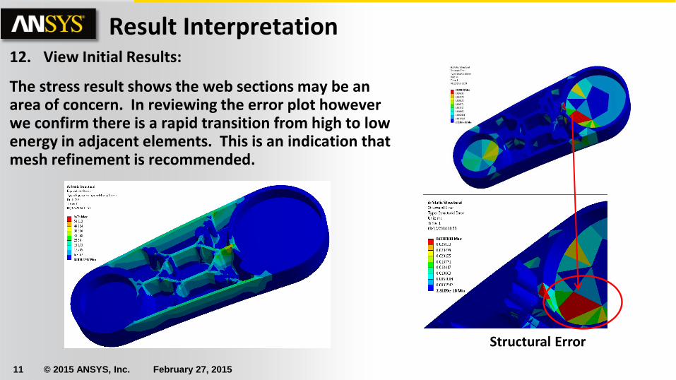
Result Interpretation 12. View Initial Results:
The stress result shows the web sections may be an area of concern. In reviewing the error plot however we confirm there is a rapid transition from high to low energy in adjacent elements. This is an indication that mesh refinement is recommended.
Structural Error
12 © 2015 ANSYS, Inc. February 27, 2015
Re-Meshing
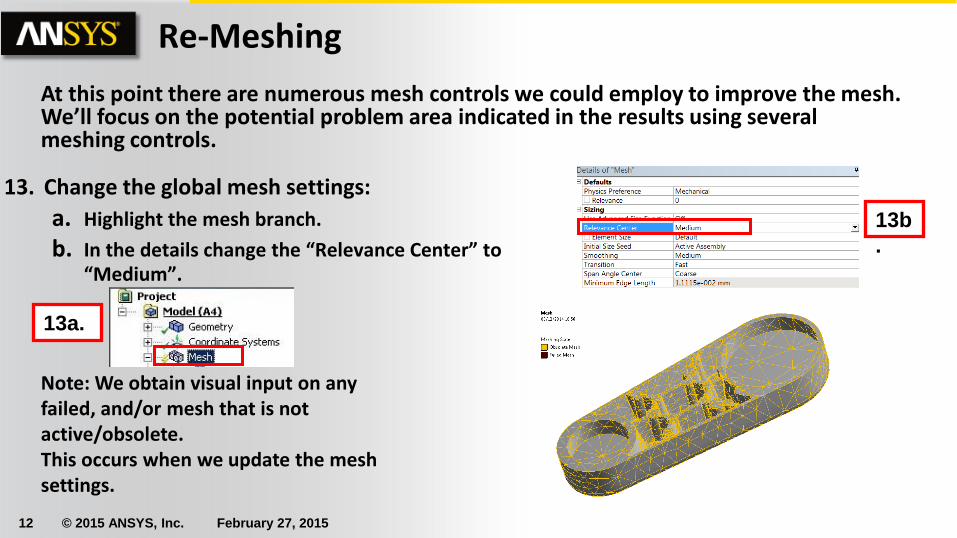
13. Change the global mesh settings:
a. Highlight the mesh branch.
b. In the details change the “Relevance Center” to “Medium”.
At this point there are numerous mesh controls we could employ to improve the mesh. We’ll focus on the potential problem area indicated in the results using several meshing controls.
13b
.
13a.
Note: We obtain visual input on any failed, and/or mesh that is not active/obsolete. This occurs when we update the mesh settings.
13 © 2015 ANSYS, Inc. February 27, 2015
. . . Re-Meshing
14d.
14c.
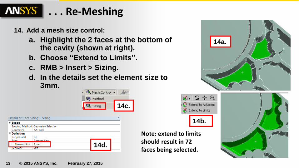
14. Add a mesh size control:
a. Highlight the 2 faces at the bottom of the cavity (shown at right).
b. Choose “Extend to Limits”.
c. RMB > Insert > Sizing.
d. In the details set the element size to 3mm.
14a.
14b.
Note: extend to limits should result in 72 faces being selected.
14 © 2015 ANSYS, Inc. February 27, 2015
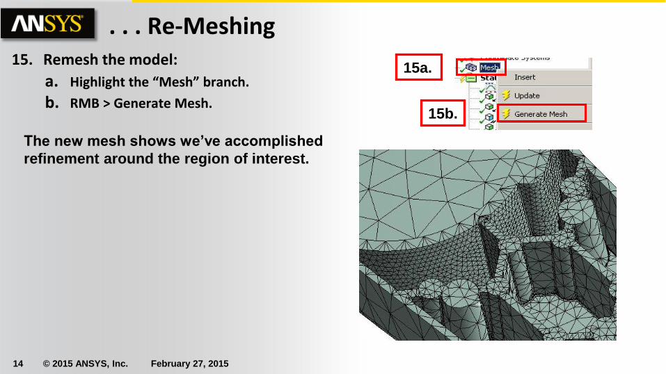
. . . Re-Meshing 15. Remesh the model:
a. Highlight the “Mesh” branch.
b. RMB > Generate Mesh. 15b.
15a.
The new mesh shows we’ve accomplished
refinement around the region of interest.
15 © 2015 ANSYS, Inc. February 27, 2015
. . . Re-Meshing
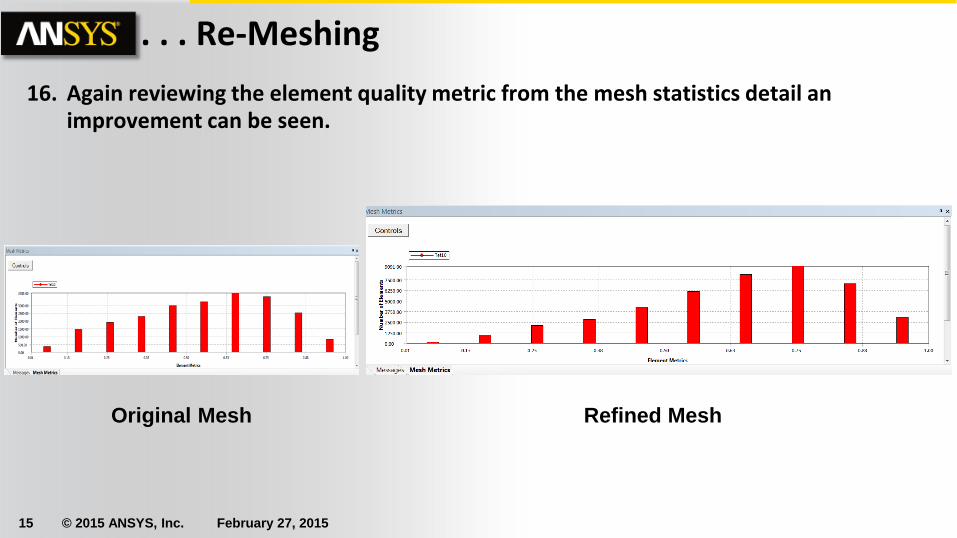
16. Again reviewing the element quality metric from the mesh statistics detail an improvement can be seen.
Original Mesh Refined Mesh
16 © 2015 ANSYS, Inc. February 27, 2015
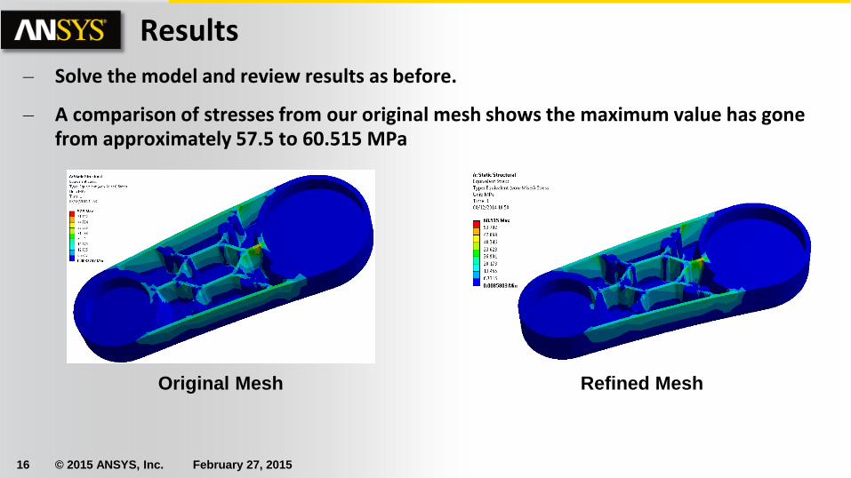
Results
– Solve the model and review results as before.
– A comparison of stresses from our original mesh shows the maximum value has gone from approximately 57.5 to 60.515 MPa
Original Mesh Refined Mesh
17 © 2015 ANSYS, Inc. February 27, 2015
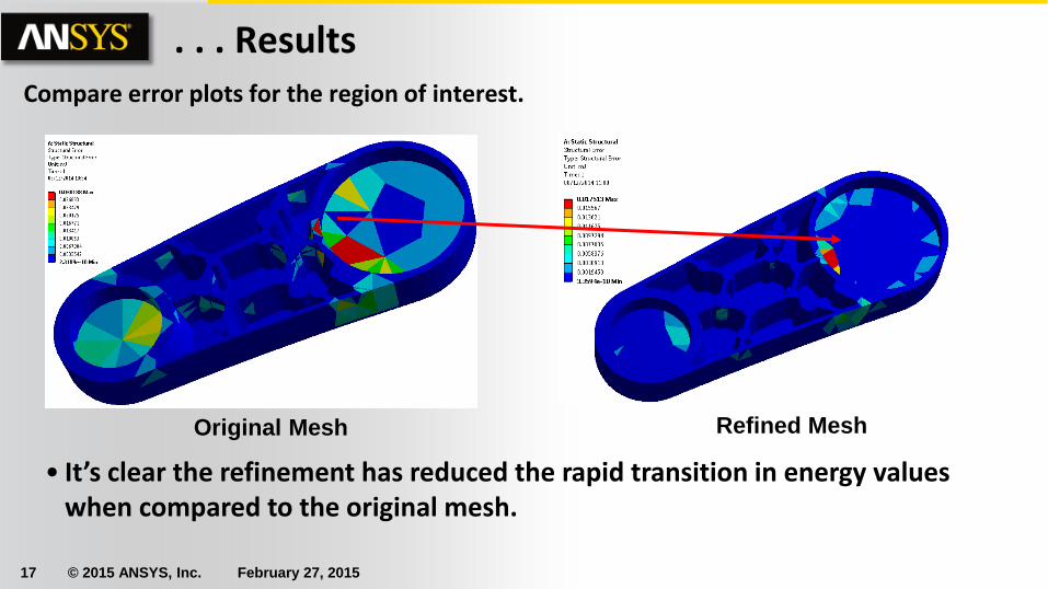
. . . Results Compare error plots for the region of interest.
• It’s clear the refinement has reduced the rapid transition in energy values when compared to the original mesh.
Original Mesh Refined Mesh

18 © 2015 ANSYS, Inc. February 27, 2015
Conclusion
Notice that there are still areas of high energy transition in the model. Our mesh refinement has addressed our stated goal but not the entire model. Each simulation is unique and will require different approaches to insure high quality results.
19 © 2015 ANSYS, Inc. February 27, 2015
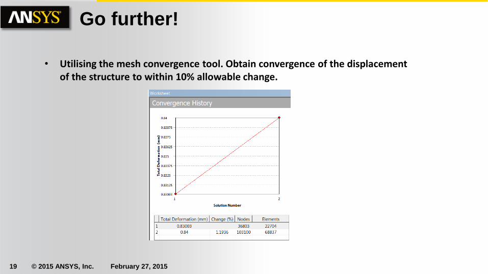
Go further!
• Utilising the mesh convergence tool. Obtain convergence of the displacement of the structure to within 10% allowable change.