Embed Size (px)
Citation preview
WS19-1PAT302, Workshop 19, December 2004Copyright2004 MSC.Software Corporation
WORKSHOP 19
GLOBAL/LOCAL MODELING USINGFEM FIELDS

WS19-2PAT302, Workshop 19, December 2004Copyright2004 MSC.Software Corporation

WS19-3PAT302, Workshop 19, December 2004Copyright2004 MSC.Software Corporation
Problem Description This exercise is used to demonstrate how to map displacement results from
the analysis of a global(overall) model onto the perimeter of a local(detail/component of overall) model. The local model is used for an analysis toobtain results for the detail/component.
The global model and its results are read into an MSC.Patran database. Theresults are used in the creation of a vector FEM field.
The FEM field is used to map the global model displacement results onto thelocal model perimeter. Also, a pressure load is applied to the local model. Ananalysis of the local model is performed.
The displacement results for both global and local models are compared.

WS19-4PAT302, Workshop 19, December 2004Copyright2004 MSC.Software Corporation
Suggested Exercise Steps1. Open a new database.2. Create a group for the global model.3. Use analysis form to read model and results for global model.4. Turn off all labels and reset the view to an isometric view.5. Create a group for the local model.6. Use analysis form to read local model.7. Post only the group for the global model for displaying its results.8. Display the deflections and stresses of the global model.9. Set the displacements to true scale 1.0.10. Create a vector plot of displacements for the global model.11. With the vector plot displayed, create a continuous, spatial, Vector
FEM field using the global displacements.12. Post only the detailed local panel model.13. Create a group to be used for creating LBCs for the local model.14. Create a load case for the local model LBCs.
WS19-5PAT302, Workshop 19, December 2004Copyright2004 MSC.Software Corporation
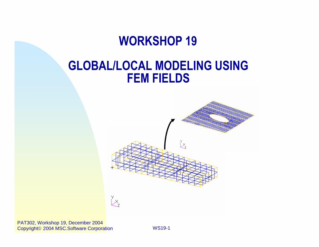
Suggested Exercise Steps (continued)15. Create a Loads/BCs for the local model.16. Post and make current the group for the local model.17. Create a uniform pressure for the local model.18. Create a MSC.Nastran input file for analysis of local model.19. Run MSC.Nastran.20. Access results.21. Post process results.22. Create a viewport so have one for each model.23. Post both global and local model.24. View the results for each model simultaneously.25. Quit MSC.Patran.

WS19-6PAT302, Workshop 19, December 2004Copyright2004 MSC.Software Corporation
Step 1. Create a New Database
Open database.a. File : New.b. Enter quarter_plate for File
Name.c. Click OK.d. Under New Model
Preferences, select Basedon Model Tolerance.
e. Select MSC.NASTRAN forAnalysis Code.
f. Select Structural forAnalysis Type.
g. Click on OK.
a
g
f
e
d
cb
WS19-7PAT302, Workshop 19, December 2004Copyright2004 MSC.Software Corporation
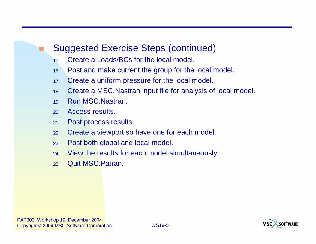
Step 2. Create a Group for Global Model
Create a group and make it currentfor the global model as follows.
a. Group : Create…b. Enter global_loads_model
for New Group Name.c. Select the Make Current and
Unpost All Other Groupscheck boxes.
d. Click on Apply.e. Click on Cancel.
ed
c
b
a

WS19-8PAT302, Workshop 19, December 2004Copyright2004 MSC.Software Corporation
Step 3. Use Analysis to Read Model/Results for Global
Use Analysis to read in both themodel and results of the GlobalLoads Model.
a. Analysis : Access Results /Read Output2 / Both.
b. Click Select ResultsFile…
c. Select multi_cell_box.op2for Select File.
d. Click on OK.e. Click on Apply.
e
d
c
b
a

WS19-9PAT302, Workshop 19, December 2004Copyright2004 MSC.Software Corporation
Set the display options to get abetter representation of themodel.
a. Click on Hide all entitylabels.
b. Click on Iso1 view.c. Click on Fit view.
Step 4. Turn off All Labels

WS19-10PAT302, Workshop 19, December 2004Copyright2004 MSC.Software Corporation
Create another group, making itcurrent, called panel_model.
a. Group : Create…b. Enter panel_model for New
Group Name.c. Select the Make Current and
Unpost All Other Groupstoggles.
d. Click on Apply.e. Click on Cancel.
Step 5. Create a Group for Local Model
ed
c
b
a
Note that the viewport iscleared

WS19-11PAT302, Workshop 19, December 2004Copyright2004 MSC.Software Corporation
Step 6. Use Analysis to Read Model for Local
Under, Analysis, read in aMSC.NASTRAN input deckthat represents the detailedpanel stress model.
a. Analysis: Read InputFile / Model Data.
b. Click on EntitySelection…
c. Click on DefineOffsets…
d. Enter 1000 for InputOffset Value for theNodes row and pressthe Enter key.
e. Enter 1000 for InputOffset Value for theElements row andpress the Enter key.
f. Click on OK.g. Click on OK.
ed
cb
ad

WS19-12PAT302, Workshop 19, December 2004Copyright2004 MSC.Software Corporation
Select the input file to read intothe input deck.
a. Click on Select InputFile..
b. Select panel.bdf forSelect File.
c. Click on OK.d. Click on Apply.e. Click OK for the Nastran
input file summary.
c
b
a
Step 6. Use Analysis to Read Model for Local
WS19-13PAT302, Workshop 19, December 2004Copyright2004 MSC.Software Corporation
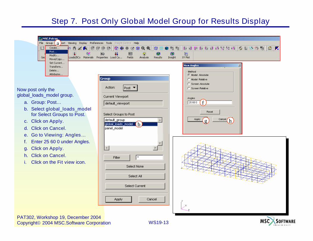
Step 7. Post Only Global Model Group for Results Display
Now post only theglobal_loads_model group.
a. Group: Post…b. Select global_loads_model
for Select Groups to Post.c. Click on Apply.d. Click on Cancel.e. Go to Viewing: Angles…f. Enter 25 60 0 under Angles.g. Click on Apply.h. Click on Cancel.i. Click on the Fit view icon.
hg
f
b
a

WS19-14PAT302, Workshop 19, December 2004Copyright2004 MSC.Software Corporation
Look at the deflection and stresses ofthe global loads model using the basicResults form.
a. Results: Create / Quick Plot.b. Click on the Selects Results
icon.c. Select Default, Static Subcase
for Select Result Case(s).d. Select Stress Tensor for Select
Fringe Result.e. Select Displacements,
Translational for SelectDeformation Result.
f. Click on Apply.
Step 8. Global Model Deflections and Stresses
f
e
d
a
b
c

WS19-15PAT302, Workshop 19, December 2004Copyright2004 MSC.Software Corporation
Now select the displacements toshow true values (scale factor=1.0,direct multiplication).
a. Select Deform Attributes iconb. Select the True Scale toggle.c. Enter 1.0 for Scale Factor.d. Click on Apply.e. After observing the modified
results, reset the graphics.
Step 9. Set the Displacements to True Scale 1.0
c
b
a

WS19-16PAT302, Workshop 19, December 2004Copyright2004 MSC.Software Corporation
Step 10. Create a Vector Plot of Displacements
Now, create a vector plot of displacements.a. Results: Create / Marker / Vector.b. Select Default, Static Subcase for
Select Result Case(s).c. Select Displacements, Translational
for Select Vector Result.d. Click the Display Attributes icon
e. Deselect Show Vector Label.f. Click on Apply.
e
d
c
a
b

WS19-17PAT302, Workshop 19, December 2004Copyright2004 MSC.Software Corporation
The model should now appear as follows:
Step 10. Create a Vector Plot of Displacements (Cont.)

WS19-18PAT302, Workshop 19, December 2004Copyright2004 MSC.Software Corporation
Step 11. Create a Vector FEM Field From Global Displacements
With the vector plot displayed, create acontinuous, spatial, vector FEM field calledDisplacements_Global_Model.
a. Fields: Create / Spatial / FEM.b. Enter Displacements_ Global_Model
under Field Name.c. Select Continuous for FEM Field
Definition.d. Select Vector for Field Type.e. Select All Groups for Mesh/Results
Group Filter.f. Select global_loads_model for Select
Group.g. Click on Options…h. Select Linear Extrapolation for
Extrapolation Option.i. Click on OK.j. Click on Apply.k. Reset the Graphics.
j
i
h
g
f
e
d
c
b
a

WS19-19PAT302, Workshop 19, December 2004Copyright2004 MSC.Software Corporation
Now post only the group panel_model;it is the detailed model of the panel.
a. Group: Post…b. Select panel_model for Select
Groups to Post.c. Click on Apply.d. Click on Cancel.
Step 12. Post Only the Local Model Group for LBCs Creation
b
a

WS19-20PAT302, Workshop 19, December 2004Copyright2004 MSC.Software Corporation
Create a group namedPanel_Model_Edge_Nodes.
a. Group: Create.b. Enter Panel_Model_ Edge_Nodes
for New Group Name.c. Select Make Current and Unpost
All Other Groups.d. Enter Node 10000 T # for Entity
Selection.e. Click on Apply.f. Click on Cancel.
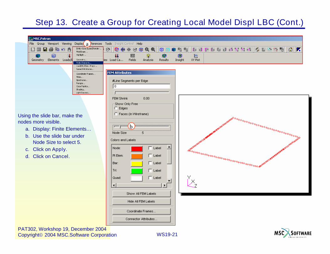
Step 13. Create a Group for Creating Local Model Displ LBC
a
b
c
d
WS19-21PAT302, Workshop 19, December 2004Copyright2004 MSC.Software Corporation
Using the slide bar, make thenodes more visible.
a. Display: Finite Elements…b. Use the slide bar under
Node Size to select 5.c. Click on Apply.d. Click on Cancel.
b
a
Step 13. Create a Group for Creating Local Model Displ LBC (Cont.)

WS19-22PAT302, Workshop 19, December 2004Copyright2004 MSC.Software Corporation
Create a static load case calledPanel_Model_Loads.
a. Load Cases: Createb. Enter Panel_Model_Loads
for Load Case Name.c. Select Make Current.d. Select Static for Type.e. Click on Apply.
Step 14. Create a Static Load Case for Local Model
d
cb
a

WS19-23PAT302, Workshop 19, December 2004Copyright2004 MSC.Software Corporation
Create an enforced nodal displacementboundary condition named Panel EnforcedDisplacements.
a. Loads/BCs: Create / Displacement /Nodal.
b. Enter Panel Enforced Displacementsfor New Set Name.
c. Click on Input Data…d. Select Displacements_Global_Model in
Spatial Fields databox for Translations<T1 T2 T3>.
e. Click OK.f. Click on Select Application Region…g. Select the FEM Filter.h. Screen pick all the nodes in the
viewport for Select Nodes.i. Click on Add.j. Click on OK.k. Click on Apply.
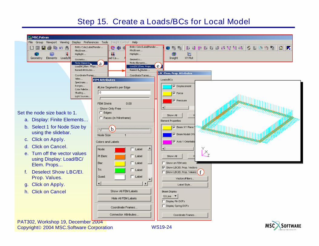
Step 15. Create a Loads/BCs for Local Model
j
i
h
g
f e
d
c
b
a
d
WS19-24PAT302, Workshop 19, December 2004Copyright2004 MSC.Software Corporation
Set the node size back to 1.a. Display: Finite Elements…b. Select 1 for Node Size by
using the slidebar.c. Click on Apply.d. Click on Cancel.e. Turn off the vector values
using Display: Load/BC/Elem. Props…
f. Deselect Show LBC/EI.Prop. Values.
g. Click on Apply.h. Click on Cancel
a e
Step 15. Create a Loads/BCs for Local Model
b
f

WS19-25PAT302, Workshop 19, December 2004Copyright2004 MSC.Software Corporation
Step 16. Post and Make Current the Local Model
Post and make current the PanelModel.
a. Group: Post…b. Select panel_model for
Select Groups to Post.c. Click on Apply.d. Click on Cancel.
b
a

WS19-26PAT302, Workshop 19, December 2004Copyright2004 MSC.Software Corporation
Create a uniform pressure called PanelPressure applied to all 2D quads onthe top surface.
a. Loads/BCs: Create / Pressure /Element Uniform.
b. Enter Panel Pressure for NewSet Name.
c. Select 2D for Target ElementType.
d. Click on Input Data…e. Enter 2.25 for Top Surf
Pressure.f. Click on OK.g. Click on Select Application
Region…h. Select the FEM Filter.i. Screen pick all the elements in
the viewport for Select 2DElements or Edges.
j. Click on Add.k. Click on OK.l. Click on Apply.
Step 17. Create a Uniform Pressure for Local Model
l
k
i
j
h
g
c
d
b
a
f
e

WS19-27PAT302, Workshop 19, December 2004Copyright2004 MSC.Software Corporation
Illustrated below is the model. After observingthis view, reset the graphics.
Step 17. Create a Uniform Pressure for Local Model

WS19-28PAT302, Workshop 19, December 2004Copyright2004 MSC.Software Corporation
Use Analysis Deck pick to create anMSC.Nastran input file. Call the jobname new_panel.
a. Analysis: Analyze / SelectedGroup / Analysis Deck.
b. Enter new_panel for JobName.
c. Click on Select Group, thenselect Select Current Group.
d. Click on TranslationParameters…
e. Select OP2 for Data Output.f. Select Text for OUTPUT2
Format.g. Click on OK.h. Click on Solution Type…i. Select Linear Static for
Solution Type.j. Click on Solution
Parameters…k. Enter 1.0 for Plate Rz
Stiffness Factor.l. Click on OK.m. Click on OK.
Step 18. Create MSC.Nastran Input File for Local Model
j
i
f
e
dc
b
a
h

WS19-29PAT302, Workshop 19, December 2004Copyright2004 MSC.Software Corporation
Continue to create the input deck.a. Click on Subcases…b. Set Action to Create.c. Enter Panel_Model for
Subcase Name.d. Select Panel_Model_Loads
for Available Load Cases.e. Click on Apply.f. Click on Cancel.g. Click on Subcase Select…h. Select Panel_Model for
Subcases For SolutionSequence: 101.
i. Click on OK.j. Click on Apply.
i
h
g fe
d
c
a
b
Step 18. Create MSC.Nastran Input File for Local Model (Cont.)

WS19-30PAT302, Workshop 19, December 2004Copyright2004 MSC.Software Corporation
If MSC.Nastran is on the network, thejob can submitted using the filenew_panel.bdf for analysis, thenimport the results file,new_panel.op2, into the databaseand look at the model stresses anddeformations.
a. Run MSC.Nastran.b. Find and Open
new_panel.bdf.c. Click on Open.d. Click on Run.e. Check for fatal errors by
opening up the filenew_panel.f06 (it is a text file)and searching for the word“fatal”. If no fatal errors exist,then the analysis completedsuccessfully.
Step 19. Run the Analysis
b c
d

WS19-31PAT302, Workshop 19, December 2004Copyright2004 MSC.Software Corporation
Continue to view results in PATRAN.a. Analysis: Access Results / Read
Output2 / Result Entities.b. Click on Select Results File…c. Select new_panel.op2.d. Click on OK.e. Click on Apply.
Step 20. Access Results
c
b
a

WS19-32PAT302, Workshop 19, December 2004Copyright2004 MSC.Software Corporation
View the results in a fringe plot.a. Results: Create / Fringe.b. Select Panel_Model_Loads, Static Subcase for Select
Result Case(s).c. Select Displacements, Translational for Select Fringe
Result.d. Click on Apply.
Step 21. Post Process Results
d
c
b
a

WS19-33PAT302, Workshop 19, December 2004Copyright2004 MSC.Software Corporation
The model should appear as follows:
Step 21. Post Process Results (Cont.)

WS19-34PAT302, Workshop 19, December 2004Copyright2004 MSC.Software Corporation
Compare the two models.a. Viewport: Create…b. Enter global_load for New
Viewport Name.c. Click on Apply.d. Viewport: Tile
Step 22. Create a Viewport so Have one for Each Model
c
b
a
d

WS19-35PAT302, Workshop 19, December 2004Copyright2004 MSC.Software Corporation
Change the group being posted in the viewport global_load.a. Make the viewport global_load active by clicking inside the
window.b. Groups: Post…c. Select global_loads_model.d. Click on Apply.e. Click on Cancel.
Step 23. Post Model to Each Viewport
c
b
a

WS19-36PAT302, Workshop 19, December 2004Copyright2004 MSC.Software Corporation
Panel_Model_Loads, Static Subcase
View the results for the model in the group global_loads_model.a. Results: Create / Fringe.b. Select Default, Static Subcase for Select Result Case(s).c. Select Displacements, Translational for Select Fringe
Result.d. Select Y component for Quantity.e. Click on Apply.
Step 24. View Results for Each Model Simultaneously
d
c
a
b

WS19-37PAT302, Workshop 19, December 2004Copyright2004 MSC.Software Corporation
In order to simplify comparing the twomodel’s result a single range will be used.
a. Click inside the viewport thatcontains the panel model(default_viewport) to make it active.
b. Results: Create / Fringec. Select Panel_Model_Loads, Static
Subcased. Select Displacements, Translationale. Select the Display Attributes icon.f. Click on Range…g. Select Fri_default_Fringe2.h. Select Post Range to Viewport.i. Click on OK.j. Click on Apply
h
g
f
b
Step 24. View Results for Each Model Simultaneously
c
d
e

WS19-38PAT302, Workshop 19, December 2004Copyright2004 MSC.Software Corporation
Compare the viewports. Notice that the colors on the edges ofthe panel model are identical to those of the global model.
Step 24. View Results for Each Model Simultaneously

WS19-39PAT302, Workshop 19, December 2004Copyright2004 MSC.Software Corporation
Quite MSC.PATRAN.a. File : Close.
This ends this exercise.
Step 25. Quit MSC.Patran
a

WS19-40PAT302, Workshop 19, December 2004Copyright2004 MSC.Software Corporation


![42. Hardware, Software, and Service Ecosystemsst.inf.tu-dresden.de/files/teaching/ws19/saab/slides/42-saab-softwar… · 3 Software as a Business References [Popp] Karl Michael Popp](https://img.pdfslide.net/doc/110x75/5f79555576bf5a79646aad77/42-hardware-software-and-service-3-software-as-a-business-references-popp-karl.jpg)