Embed Size (px)
Citation preview
WS4-1PAT302, Workshop 4, December 2004Copyright2004 MSC.Software Corporation
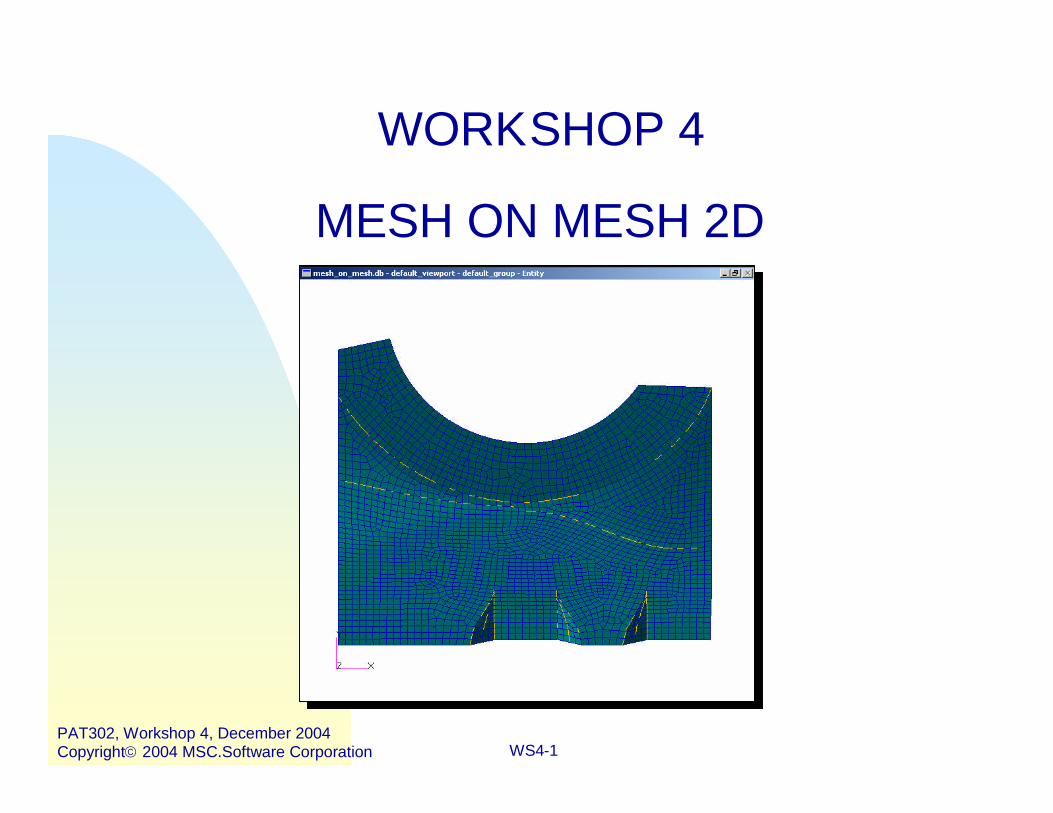
WORKSHOP 4
MESH ON MESH 2D

WS4-2PAT302, Workshop 4, December 2004Copyright2004 MSC.Software Corporation
WS4-3PAT302, Workshop 4, December 2004Copyright2004 MSC.Software Corporation
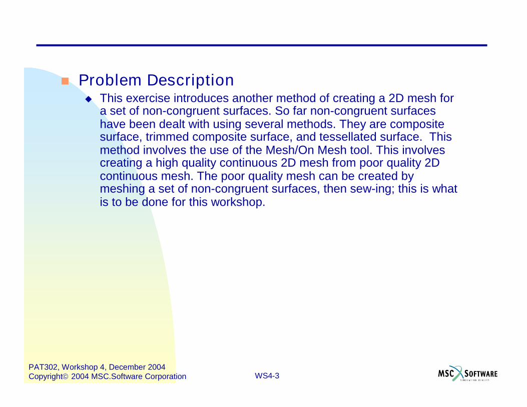
Problem Description This exercise introduces another method of creating a 2D mesh for
a set of non-congruent surfaces. So far non-congruent surfaceshave been dealt with using several methods. They are compositesurface, trimmed composite surface, and tessellated surface. Thismethod involves the use of the Mesh/On Mesh tool. This involvescreating a high quality continuous 2D mesh from poor quality 2Dcontinuous mesh. The poor quality mesh can be created bymeshing a set of non-congruent surfaces, then sew-ing; this is whatis to be done for this workshop.
WS4-4PAT302, Workshop 4, December 2004Copyright2004 MSC.Software Corporation
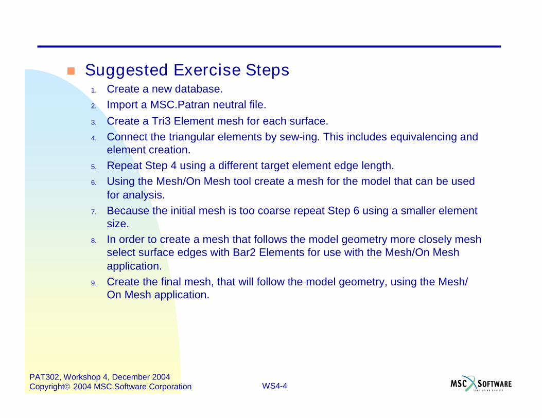
Suggested Exercise Steps1. Create a new database.2. Import a MSC.Patran neutral file.3. Create a Tri3 Element mesh for each surface.4. Connect the triangular elements by sew-ing. This includes equivalencing and
element creation.5. Repeat Step 4 using a different target element edge length.6. Using the Mesh/On Mesh tool create a mesh for the model that can be used
for analysis.7. Because the initial mesh is too coarse repeat Step 6 using a smaller element
size.8. In order to create a mesh that follows the model geometry more closely mesh
select surface edges with Bar2 Elements for use with the Mesh/On Meshapplication.
9. Create the final mesh, that will follow the model geometry, using the Mesh/On Mesh application.
WS4-5PAT302, Workshop 4, December 2004Copyright2004 MSC.Software Corporation
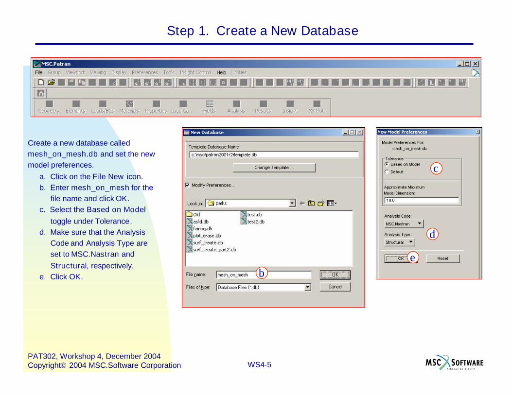
Step 1. Create a New Database
Create a new database calledmesh_on_mesh.db and set the newmodel preferences.
a. Click on the File New icon.b. Enter mesh_on_mesh for the
file name and click OK.c. Select the Based on Model
toggle under Tolerance.d. Make sure that the Analysis
Code and Analysis Type areset to MSC.Nastran andStructural, respectively.
e. Click OK. b
c
d
e
WS4-6PAT302, Workshop 4, December 2004Copyright2004 MSC.Software Corporation
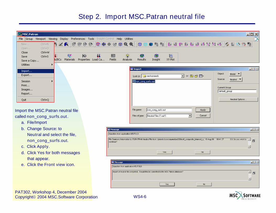
Step 2. Import MSC.Patran neutral file
Import the MSC.Patran neutral filecalled non_cong_surfs.out.
a. File/Importb. Change Source: to
Neutral and select the file,non_cong_surfs.out.
c. Click Apply.d. Click Yes for both messages
that appear.e. Click the Front view icon.
WS4-7PAT302, Workshop 4, December 2004Copyright2004 MSC.Software Corporation
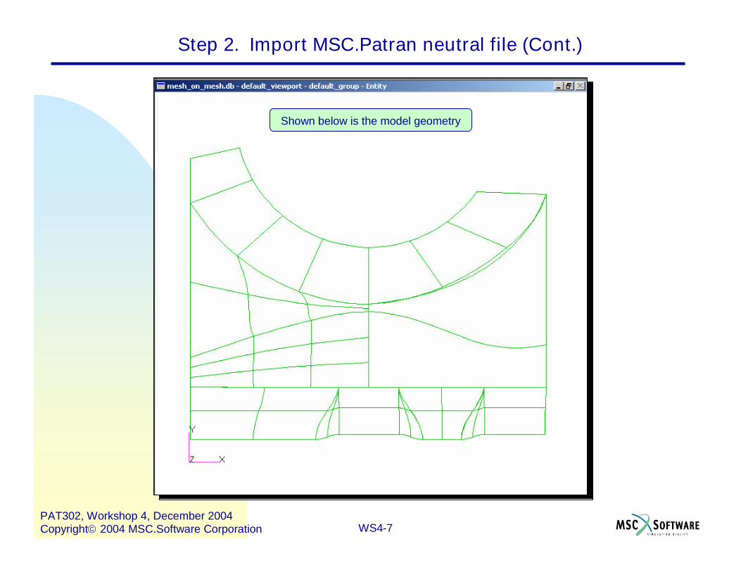
Step 2. Import MSC.Patran neutral file (Cont.)
Shown below is the model geometry
WS4-8PAT302, Workshop 4, December 2004Copyright2004 MSC.Software Corporation
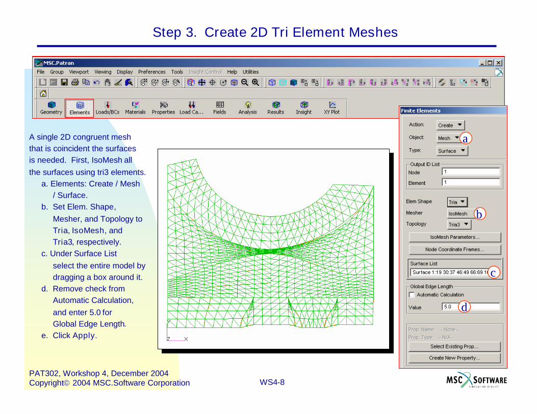
Step 3. Create 2D Tri Element Meshes
A single 2D congruent meshthat is coincident the surfacesis needed. First, IsoMesh allthe surfaces using tri3 elements.
a. Elements: Create / Mesh/ Surface.
b. Set Elem. Shape,Mesher, and Topology toTria, IsoMesh, andTria3, respectively.
c. Under Surface Listselect the entire model bydragging a box around it.
d. Remove check fromAutomatic Calculation,and enter 5.0 forGlobal Edge Length.
e. Click Apply.
a
b
d
c
WS4-9PAT302, Workshop 4, December 2004Copyright2004 MSC.Software Corporation
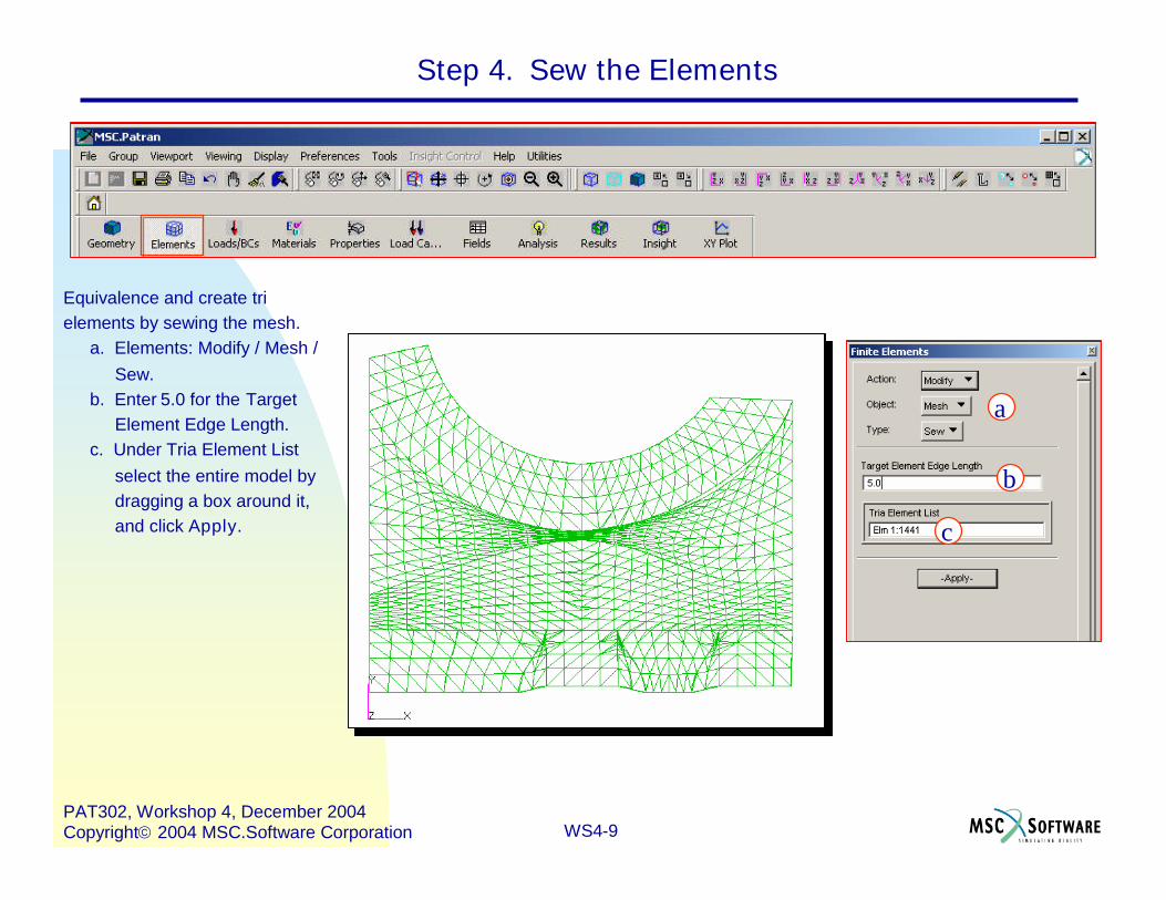
Step 4. Sew the Elements
Equivalence and create trielements by sewing the mesh.
a. Elements: Modify / Mesh /Sew.
b. Enter 5.0 for the TargetElement Edge Length.
c. Under Tria Element Listselect the entire model bydragging a box around it,and click Apply.
a
b
c
WS4-10PAT302, Workshop 4, December 2004Copyright2004 MSC.Software Corporation
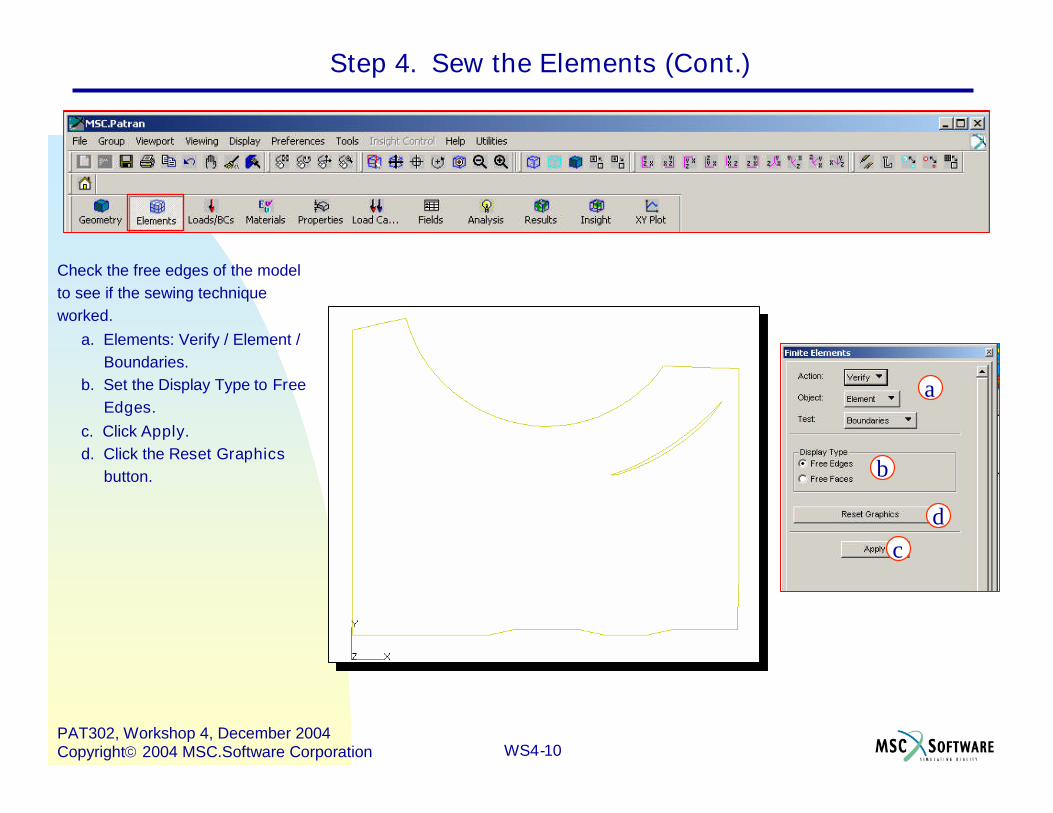
Step 4. Sew the Elements (Cont.)
Check the free edges of the modelto see if the sewing techniqueworked.
a. Elements: Verify / Element /Boundaries.
b. Set the Display Type to FreeEdges.
c. Click Apply.d. Click the Reset Graphics
button.
a
b
cd
WS4-11PAT302, Workshop 4, December 2004Copyright2004 MSC.Software Corporation
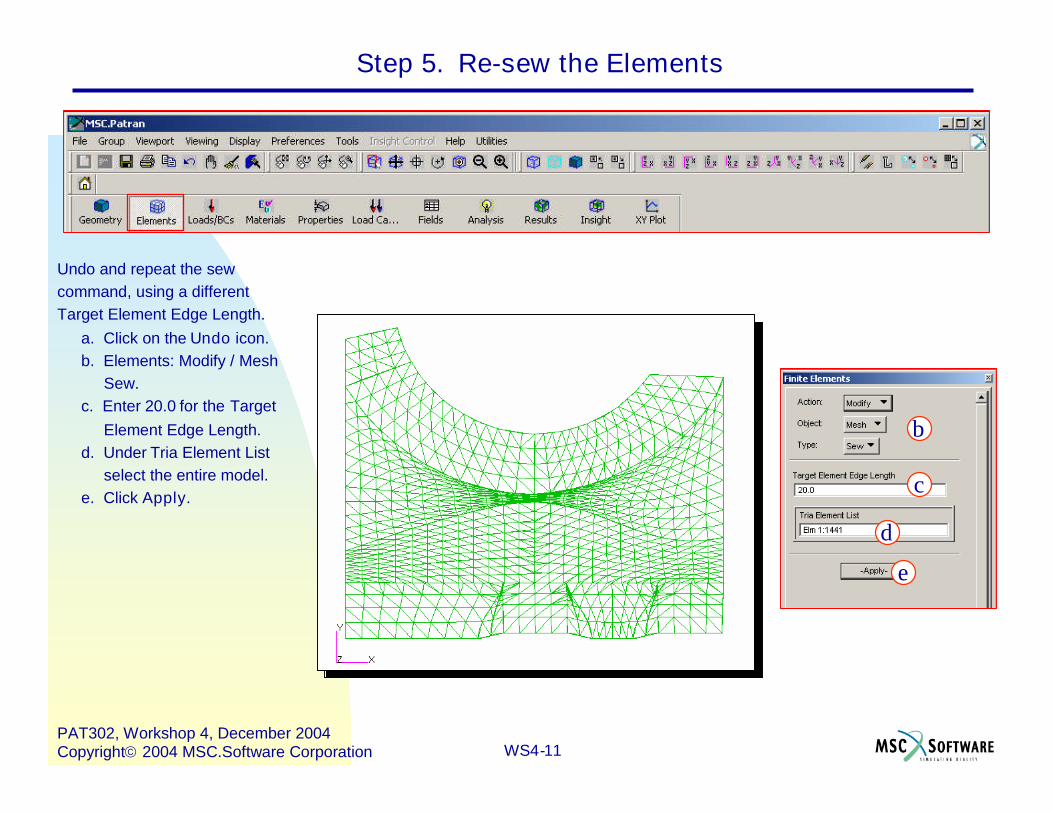
Step 5. Re-sew the Elements
Undo and repeat the sewcommand, using a differentTarget Element Edge Length.
a. Click on the Undo icon.b. Elements: Modify / Mesh
Sew.c. Enter 20.0 for the Target
Element Edge Length.d. Under Tria Element List
select the entire model.e. Click Apply.
b
c
d
e
WS4-12PAT302, Workshop 4, December 2004Copyright2004 MSC.Software Corporation
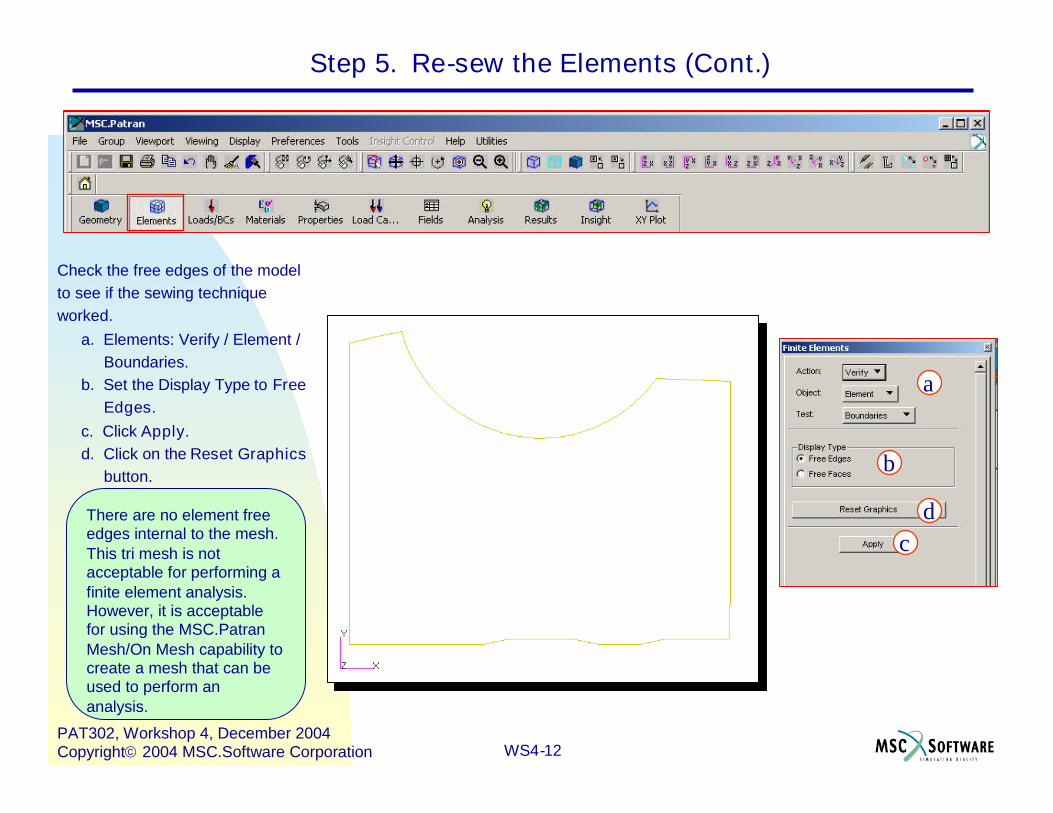
Step 5. Re-sew the Elements (Cont.)
Check the free edges of the modelto see if the sewing techniqueworked.
a. Elements: Verify / Element /Boundaries.
b. Set the Display Type to FreeEdges.
c. Click Apply.d. Click on the Reset Graphics
button.
There are no element freeedges internal to the mesh.This tri mesh is notacceptable for performing afinite element analysis.However, it is acceptablefor using the MSC.PatranMesh/On Mesh capability tocreate a mesh that can beused to perform ananalysis.
a
b
cd
WS4-13PAT302, Workshop 4, December 2004Copyright2004 MSC.Software Corporation
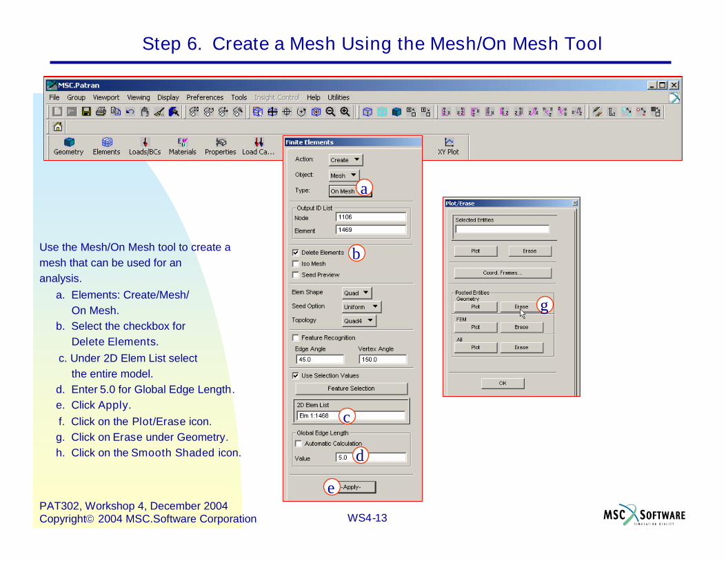
Step 6. Create a Mesh Using the Mesh/On Mesh Tool
Use the Mesh/On Mesh tool to create amesh that can be used for ananalysis.
a. Elements: Create/Mesh/On Mesh.
b. Select the checkbox forDelete Elements.
c. Under 2D Elem List selectthe entire model.
d. Enter 5.0 for Global Edge Length.e. Click Apply.f. Click on the Plot/Erase icon.g. Click on Erase under Geometry.h. Click on the Smooth Shaded icon.
a
d
e
g
c
b
WS4-14PAT302, Workshop 4, December 2004Copyright2004 MSC.Software Corporation
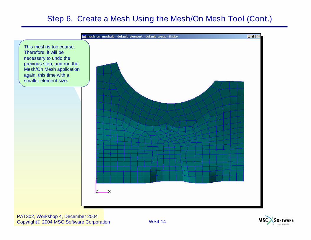
This mesh is too coarse.Therefore, it will benecessary to undo theprevious step, and run theMesh/On Mesh applicationagain, this time with asmaller element size.
Step 6. Create a Mesh Using the Mesh/On Mesh Tool (Cont.)
WS4-15PAT302, Workshop 4, December 2004Copyright2004 MSC.Software Corporation
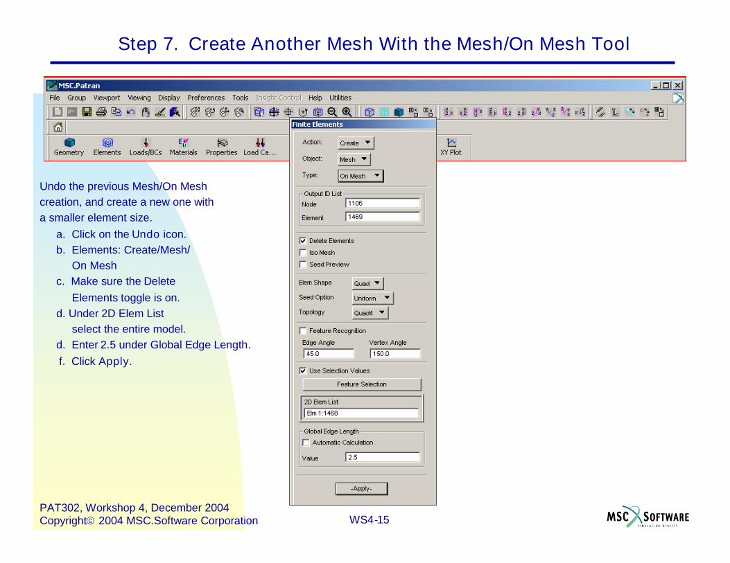
Step 7. Create Another Mesh With the Mesh/On Mesh Tool
Undo the previous Mesh/On Meshcreation, and create a new one witha smaller element size.
a. Click on the Undo icon.b. Elements: Create/Mesh/
On Meshc. Make sure the Delete
Elements toggle is on.d. Under 2D Elem List
select the entire model.d. Enter 2.5 under Global Edge Length.f. Click Apply.
WS4-16PAT302, Workshop 4, December 2004Copyright2004 MSC.Software Corporation
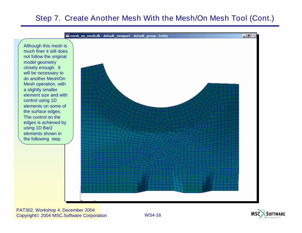
Although this mesh ismuch finer it still doesnot follow the originalmodel geometryclosely enough. Itwill be necessary todo another Mesh/OnMesh operation, witha slightly smallerelement size and withcontrol using 1Delements on some ofthe surface edges.The control on theedges is achieved byusing 1D Bar2elements shown inthe following step.
Step 7. Create Another Mesh With the Mesh/On Mesh Tool (Cont.)
WS4-17PAT302, Workshop 4, December 2004Copyright2004 MSC.Software Corporation
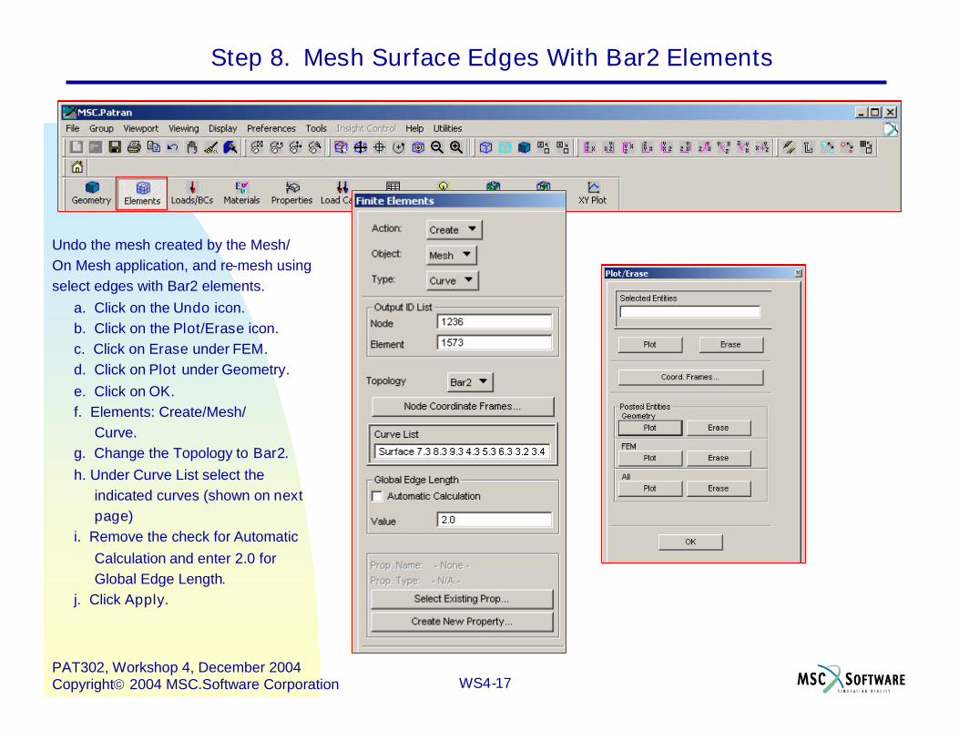
Step 8. Mesh Surface Edges With Bar2 Elements
Undo the mesh created by the Mesh/On Mesh application, and re-mesh usingselect edges with Bar2 elements.
a. Click on the Undo icon.b. Click on the Plot/Erase icon.c. Click on Erase under FEM.d. Click on Plot under Geometry.e. Click on OK.f. Elements: Create/Mesh/
Curve.g. Change the Topology to Bar2.h. Under Curve List select the
indicated curves (shown on nextpage)
i. Remove the check for AutomaticCalculation and enter 2.0 forGlobal Edge Length.
j. Click Apply.
WS4-18PAT302, Workshop 4, December 2004Copyright2004 MSC.Software Corporation
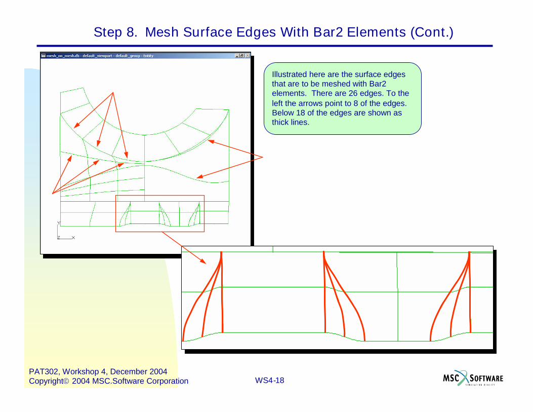
Illustrated here are the surface edgesthat are to be meshed with Bar2elements. There are 26 edges. To theleft the arrows point to 8 of the edges.Below 18 of the edges are shown asthick lines.
Step 8. Mesh Surface Edges With Bar2 Elements (Cont.)
WS4-19PAT302, Workshop 4, December 2004Copyright2004 MSC.Software Corporation
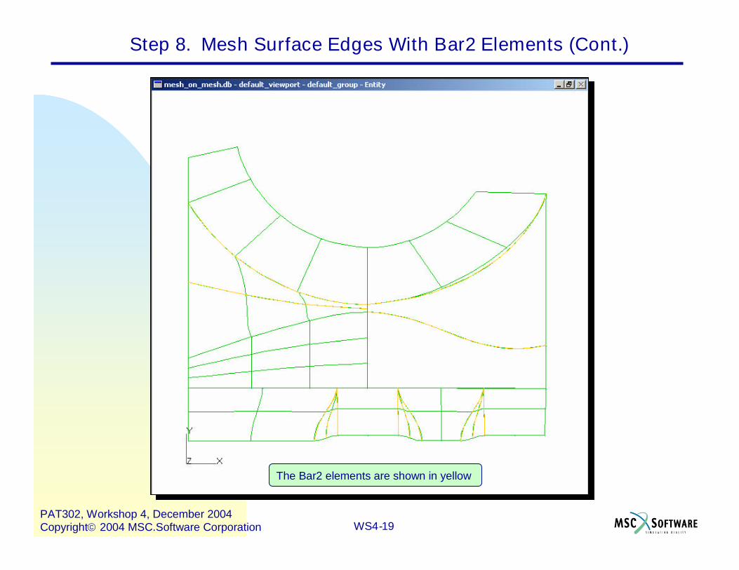
The Bar2 elements are shown in yellow
Step 8. Mesh Surface Edges With Bar2 Elements (Cont.)
WS4-20PAT302, Workshop 4, December 2004Copyright2004 MSC.Software Corporation
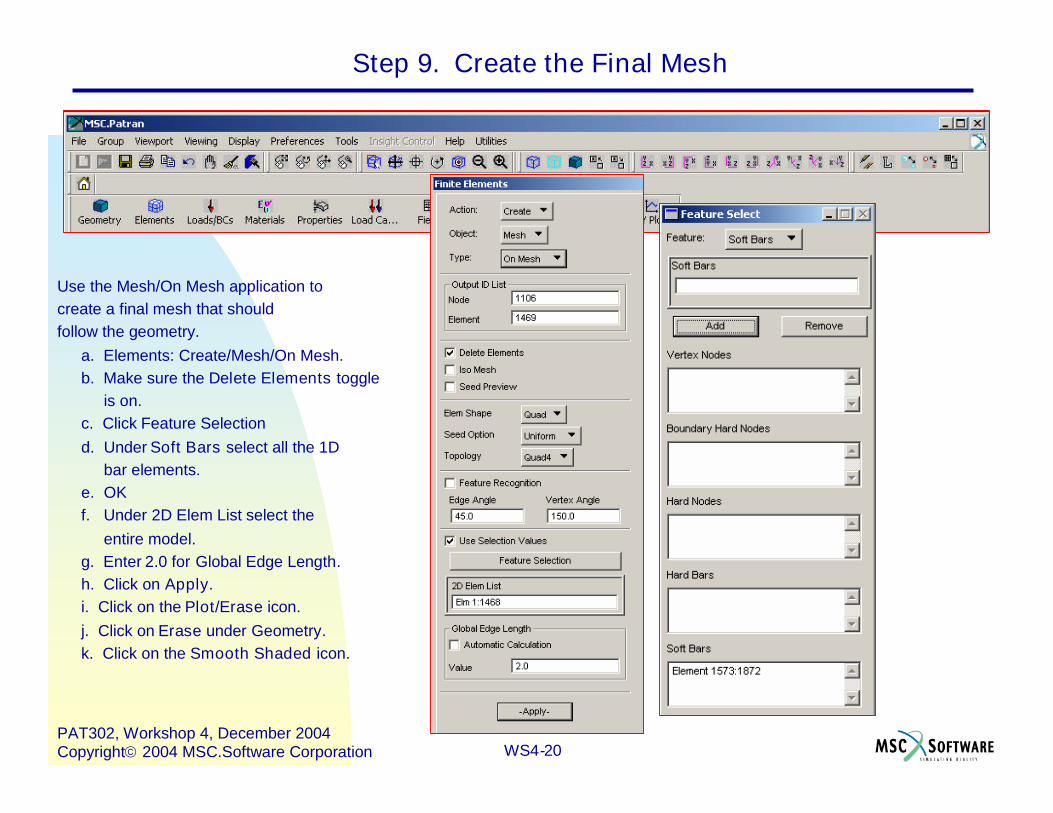
Step 9. Create the Final Mesh
Use the Mesh/On Mesh application tocreate a final mesh that shouldfollow the geometry.
a. Elements: Create/Mesh/On Mesh.b. Make sure the Delete Elements toggle
is on.c. Click Feature Selectiond. Under Soft Bars select all the 1D
bar elements.e. OKf. Under 2D Elem List select the
entire model.g. Enter 2.0 for Global Edge Length.h. Click on Apply.i. Click on the Plot/Erase icon.j. Click on Erase under Geometry.k. Click on the Smooth Shaded icon.
WS4-21PAT302, Workshop 4, December 2004Copyright2004 MSC.Software Corporation
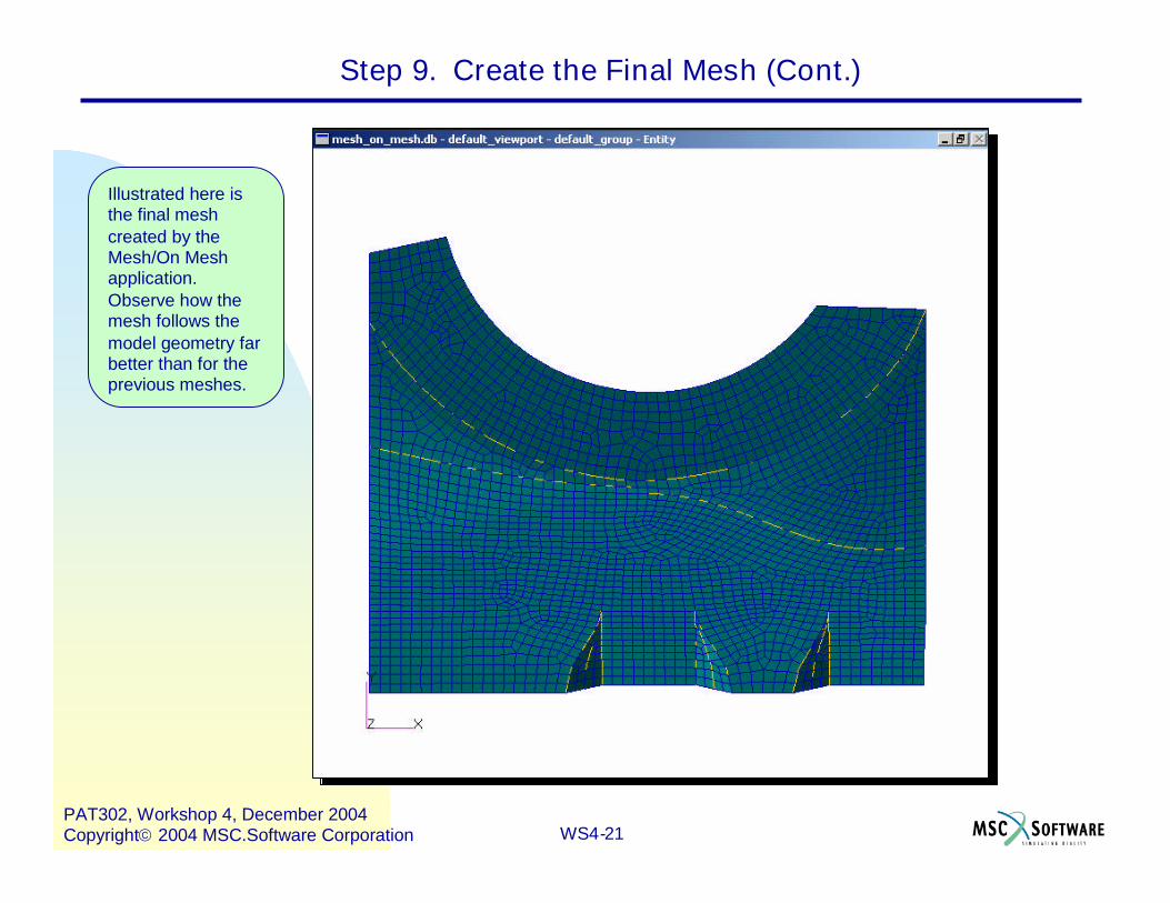
Step 9. Create the Final Mesh (Cont.)
Illustrated here isthe final meshcreated by theMesh/On Meshapplication.Observe how themesh follows themodel geometry farbetter than for theprevious meshes.
WS4-22PAT302, Workshop 4, December 2004Copyright2004 MSC.Software Corporation


![Wing meshing in SALOME - · PDF fileTUT1101R0 Wing meshing in SALOME Table of Contents 1 Log of revisions ... the SALOME meshing software [ref 2]. The mesh is made of both quadrangle](https://img.pdfslide.net/doc/110x75/5a9e9ecd7f8b9a67178b9cab/wing-meshing-in-salome-wing-meshing-in-salome-table-of-contents-1-log-of-revisions.jpg)