Embed Size (px)
Citation preview
Exposure of the general public due to GSM and UMTS base station transmitters
Dr. Christian Bornkessel,Markus Schubert IMST GmbHCarl-Friedrich-Gauß-Str. 2D–47475 Kamp-Lintfort
Prof. Dr. Matthias WuschekEM Institut GmbHCarlstraße 5D-93049 Regensburg
Workshop Dosimetry, 25.-26.07.2006

Project Overview
• Literature study on existing projects
• Characterisation of time and space field variations
• Development of measurement and calculation methods
- Focus: Check of exposure limits- In addition: Time and space averaged exposures
• Measurements in different scenarios
• Analysis of field distribution and exposure parameters

70
75
80
85
90
95
100
0 20 40 60 80 100 120 140
place [cm]
elec
tric
fiel
d st
reng
th [d
BµV
/m]
GSM 900
UMTS
Small scale field variation in space
• Small scale variations (fast fading) especially at indoor scenariosdue to multipath propagation
• Variations of 10 dB and more
Simulation: GSM 900Measurement: GSM 900 and UMTS
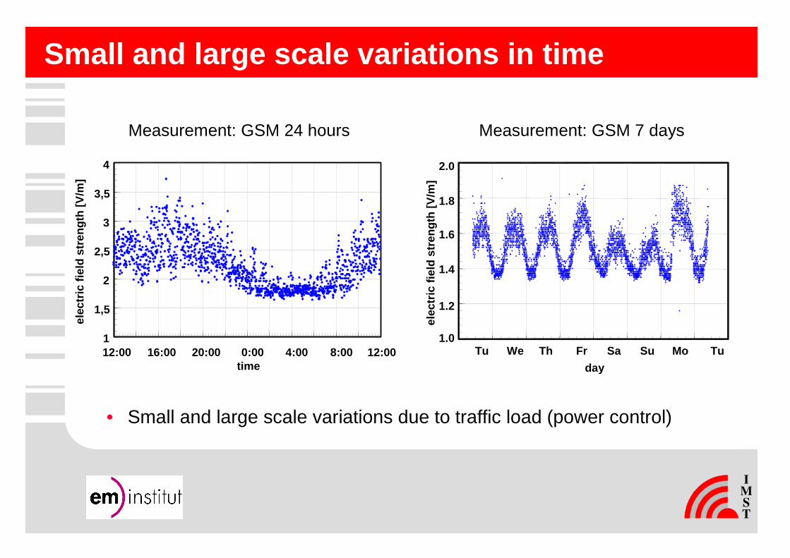
Small and large scale variations in time
time
1
1,5
2
2,5
3
3,5
4
12:00 16:00 20:00 0:00 4:00 8:00 12:00
elec
tric
fiel
d st
reng
th [V
/m]
day
Tu We Th Fr Sa Su Mo Tu
2.0
1.8
1.6
1.4
1.2
1.0
elec
tric
fiel
d st
reng
th [V
/m]
Measurement: GSM 24 hours Measurement: GSM 7 days
• Small and large scale variations due to traffic load (power control)

German Exposure Ordinance (26. BImSchV) demands ...
• Exposure limits are given as- RMS value of- electric and magnetic field strength
• Measurements have to be performed at the highest operational state of the station; otherwise they have to be extrapolatedaccordingly
• Measurements have to be performed at the place with the highest exposure
• Post processing of measurement results on basis of the maximal measured fields strengths or power densities at the measurement place
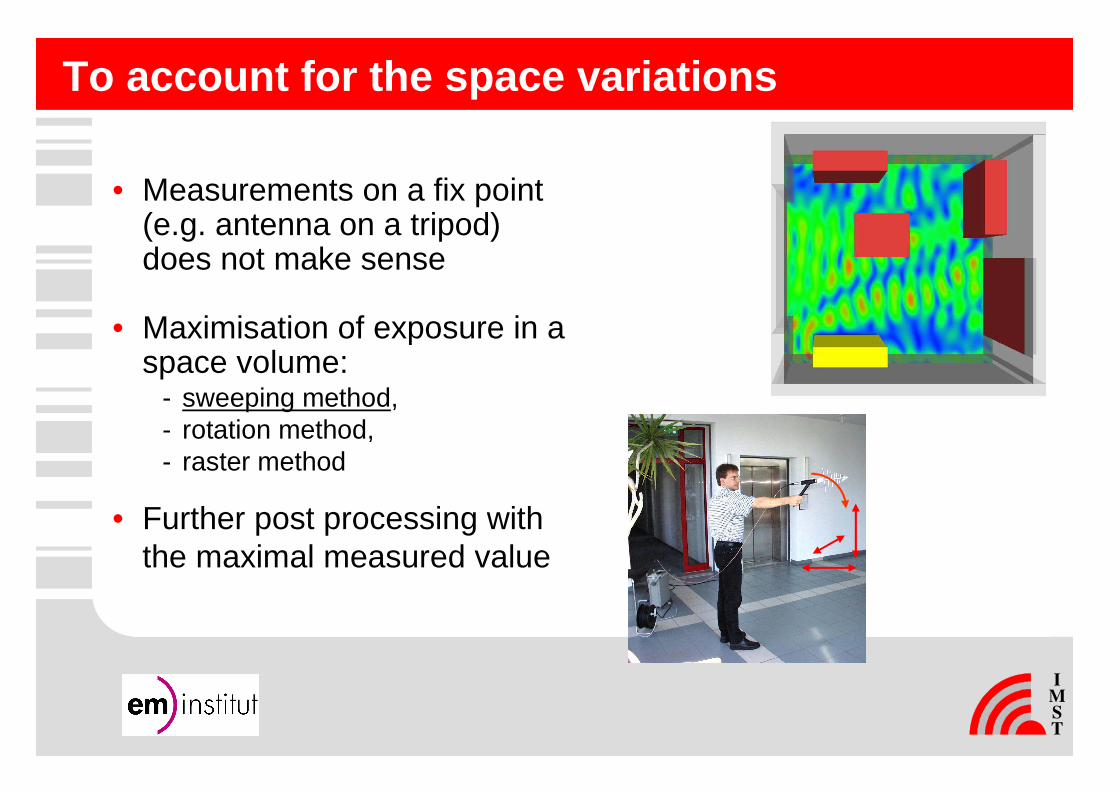
To account for the space variations
• Measurements on a fix point(e.g. antenna on a tripod) does not make sense
• Maximisation of exposure in a space volume:
- sweeping method,- rotation method,- raster method
• Further post processing withthe maximal measured value

To account for the time variations: GSM
• Frequency selectiveequipment
• Measure time constant signalling channels (BCCH)
• Extrapolate their exposure to maximal channel number
• Ignore TCH exposure
• Summarise exposures of all sectors
1820 1830 1840 1850
frequency [MHz]
50
60
70
80
90
100
110
120
BC
CH
sec
tor
1
x
x
x4
x4
elec
tric
fiel
d st
reng
th [d
BµV
/m]
x4
x
BC
CH
sec
tor
3
BC
CH
sec
tor
2
TC
HT
CH
TC
H
� Frequency hopping is automatically accounted for
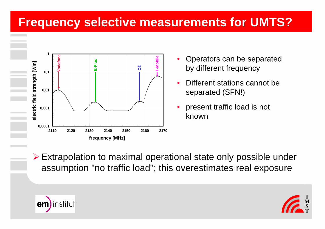
Frequency selective measurements for UMTS?
2110 2120 2130 2140 2150 2160 2170
Frequenz [MHz]
0,0001
0,001
0,01
0,1
1
Ele
ktri
sch
e F
eld
stär
ke [
V/m
]
Vod
afon
e
E-P
lus
O2
T-M
obile • Operators can be separated
by different frequency
• Different stations cannot beseparated (SFN!)
• present traffic load is not known
�Extrapolation to maximal operational state only possible under assumption "no traffic load"; this overestimates real exposure
frequency [MHz]
elec
tric
fiel
d st
reng
th [V
/m]
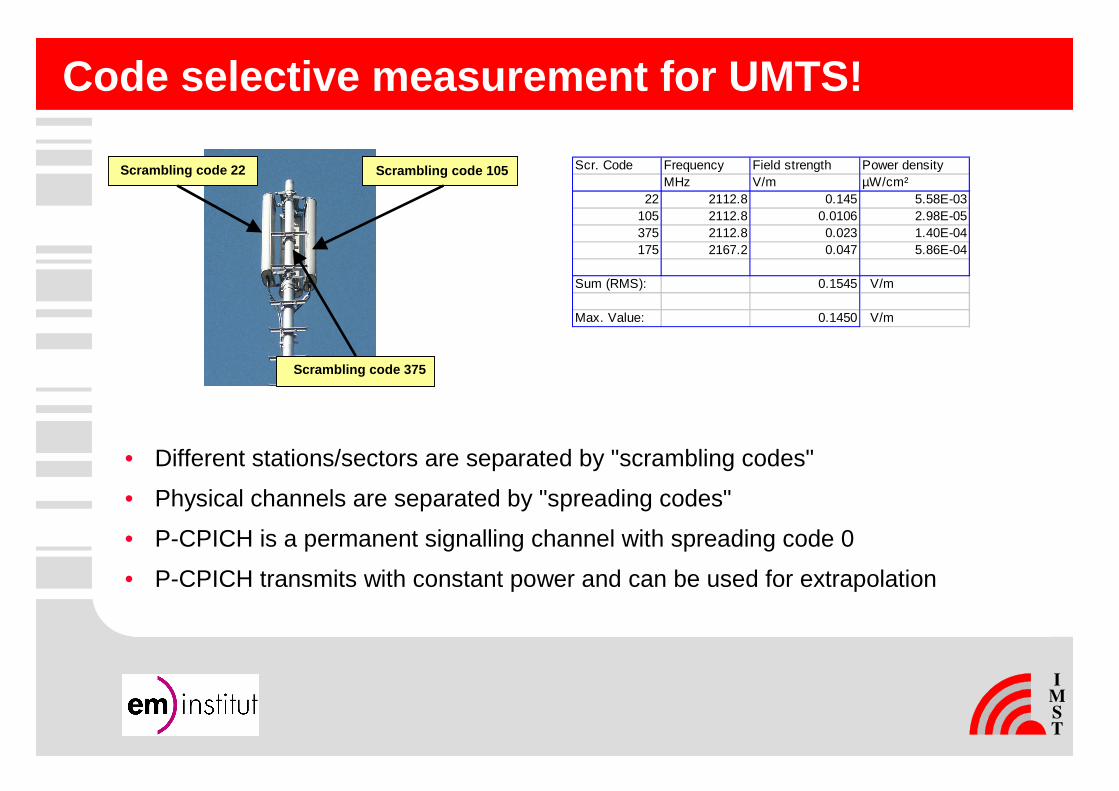
Code selective measurement for UMTS!
• Different stations/sectors are separated by "scrambling codes"
• Physical channels are separated by "spreading codes"
• P-CPICH is a permanent signalling channel with spreading code 0
• P-CPICH transmits with constant power and can be used for extrapolation
Scrambling code 105
Scrambling code 375
Scrambling code 22 Scr. Code Frequency Field strength Power densityMHz V/m µW/cm²
22 2112.8 0.145 5.58E-03105 2112.8 0.0106 2.98E-05375 2112.8 0.023 1.40E-04175 2167.2 0.047 5.86E-04
Sum (RMS): 0.1545 V/m
Max. Value: 0.1450 V/m

Detailed investigations of several code selective d evices
Rohde & SchwarzTSMU
Rohde & SchwarzFSP/ESPI with
code-selective option
Narda SRM-3000
� Investigations on measurement rate, accuracy, dynamic, linearity, reproducibility, uncertainty, ...

Analyser settings for spectral measurements
100 msAuto (Peak)100 ms (RMS)
Sweep time
RMSPeak or RMSDetector
10 MHz≥ 200 kHzVBW
5 MHz*200 kHzRBW
UMTSGSMSetting
� Wrong settings can lead to wrong results (several d B to several 10 dB)
*: Alternatives (bandwidth correction, channel power measurement) possible, but lead to overestimations at NLOS conditions

Influence of personnel on measurement antenna
• Tests in anechoic chamber (defined environment)• Parameters: ground plane lining, frequency, antenna type,
distance of the measurement personnel
measurement antenna

Results: Example 945 MHz (GSM 900)
0 0,5 1 1,5 2 2,5 3
Abstand zur Empfangsantenne [m]
-10
-5
0
5
10
rela
tive
Ab
wei
chu
ng
[d
B]
Legendelogper Pol Hbikon Pol Hlogper Pol Vbikon Pol V
0 0,5 1 1,5 2 2,5 3
Abstand zur Empfangsantenne [m]
-2
-1,5
-1
-0,5
0
0,5
1
1,5
2
rela
tive
Ab
wei
chu
ng
[d
B]
Legendelogper Pol Hbikon Pol Hlogper Pol Vbikon Pol V
w/o ground plane absorbers with ground plane absorbers
� Partially extreme influence by measurement personne l onlow directive antennas
� AT UMTS frequencies: up to 3 dB difference
distance to receive antenna [m]distance to receive antenna [m]
rela
tive
diffe
renc
e [d
B]
rela
tive
diffe
renc
e [d
B]
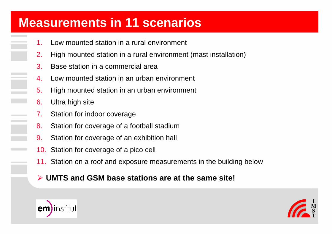
Measurements in 11 scenarios1. Low mounted station in a rural environment
2. High mounted station in a rural environment (mast installation)
3. Base station in a commercial area
4. Low mounted station in an urban environment
5. High mounted station in an urban environment
6. Ultra high site
7. Station for indoor coverage
8. Station for coverage of a football stadium
9. Station for coverage of an exhibition hall
10. Station for coverage of a pico cell
11. Station on a roof and exposure measurements in the building below
� UMTS and GSM base stations are at the same site!
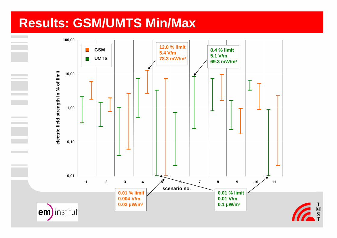
Results: GSM/UMTS Min/Max
0,01
0,10
1,00
10,00
100,00
elec
tric
fiel
d st
reng
th in
% o
f lim
it
1 2 3 4 5 6 7 8 9 10 11
GSM
UMTS
scenario no.
8.4 % limit5.1 V/m69.3 mW/m²
0.01 % limit0.01 V/m0.1 µW/m²
12.8 % limit5.4 V/m78.3 mW/m²
0.01 % limit0.004 V/m0.03 µW/m²
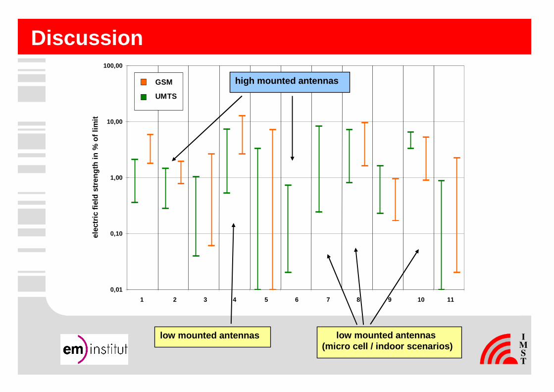
Discussion
0,01
0,10
1,00
10,00
100,00
elec
tric
fiel
d st
reng
th in
% o
f lim
it
1 2 3 4 5 6 7 8 9 10 11
GSM
UMTS
low mounted antennas (micro cell / indoor scenarios)
low mounted antennas
high mounted antennas

Distribution of results
64,4
18,4
4,33,1 3,1
1,8 2,51,2 1,2
0,0 0,0
34,9
18,3 17,5
8,77,1
8,7
1,6 1,60,0 0,8 0,8
0,0
10,0
20,0
30,0
40,0
50,0
60,0
70,0
0 - 1 1 - 2 2 - 3 3 - 4 4 - 5 5 - 6 6 - 7 7 - 8 8 - 9 9 - 10 > 10
field strength in % of limit
rela
tiv n
umbe
r of
poi
nts
in %
UMTS
GSM
median UMTS: 0.72 % of field strength limitmedian GSM: 1.75 % of field strength limit

Distance as a main factor for exposure?
0,01
0,1
1
10
1 10 100 1000 10000
distance to base station [m]
elec
tric
fiel
d st
reng
th [%
of l
imit]
Indoor
Outdoor
Answer: Outdoor no (up to approx. 200 m)Indoor yes
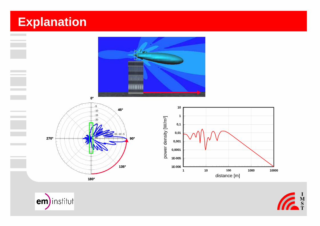
Explanation
-35-35
-30
-30
-25
-25
-20
-20
-15
-15
-10
-10
-5
-5-40
-40
180°
135°
0°
90°270°
45°
-35-35
-30
-30
-25
-25
-20
-20
-15
-15
-10
-10
-5
-5-40
-40
180°
135°
0°
90°270°
45°
1 10 100 1000 10000
Abstand d [m]
1E-006
1E-005
0,0001
0,001
0,01
0,1
1
10
Lei
stu
ng
sflu
ssd
ich
te [
W/m
2]
distance [m]
pow
er d
ensi
ty [W
/m²]
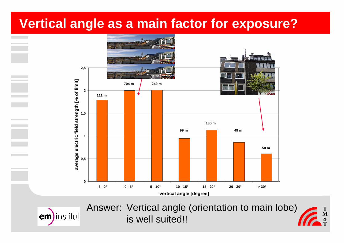
Vertical angle as a main factor for exposure?
Answer: Vertical angle (orientation to main lobe)is well suited!!
0
0,5
1
1,5
2
2,5
-6 - 0° 0 - 5° 5 - 10° 10 - 15° 15 - 20° 20 - 30° > 30°
vertical angle [degree]
aver
age
elec
tric
fiel
d st
reng
th [%
of l
imit]
111 m
704 m 249 m
99 m
136 m
49 m
50 m
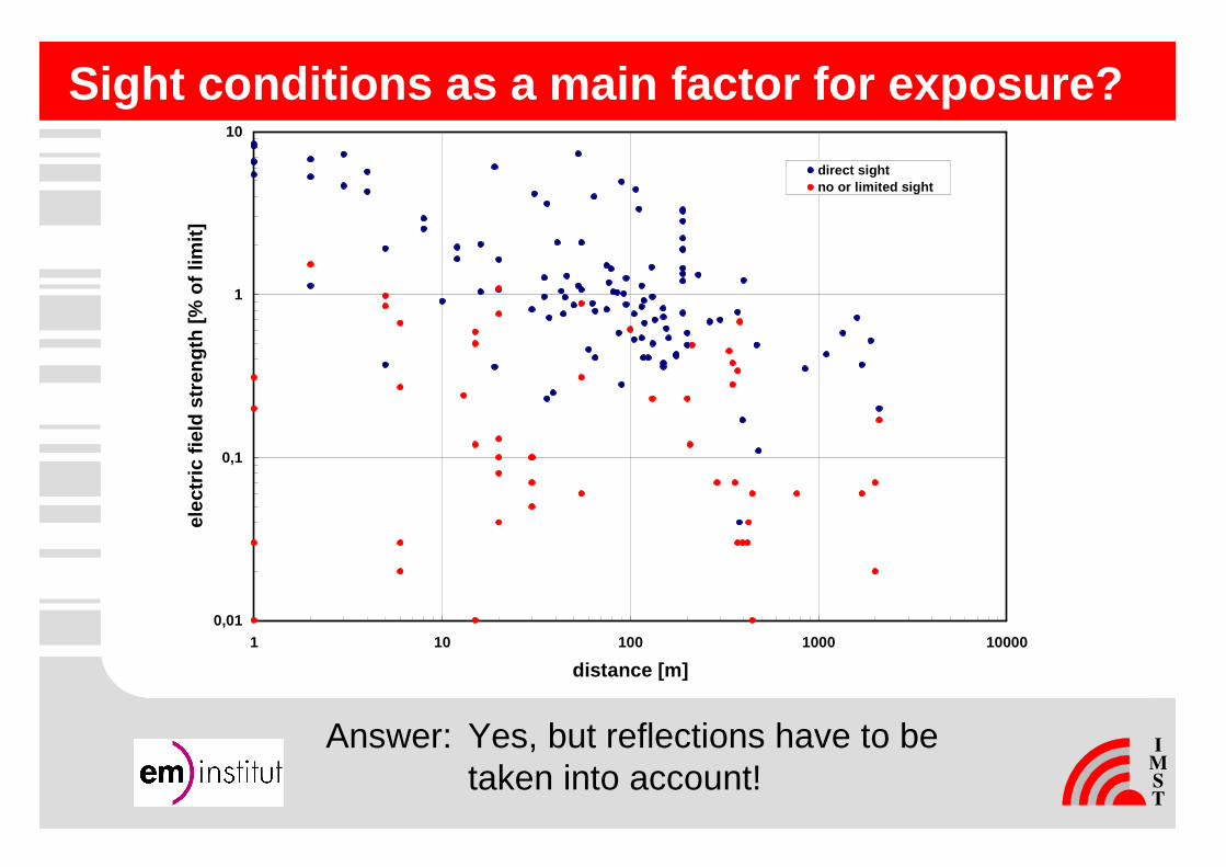
Sight conditions as a main factor for exposure?
Answer: Yes, but reflections have to betaken into account!
0,01
0,1
1
10
1 10 100 1000 10000
distance [m]
elec
tric
fiel
d st
reng
th [%
of l
imit]
direct sightno or limited sight

Relation of G
SM
/ UM
TS
exposure(1)
0 2 4 6 8 10 12 14
1.11.21.31.41.51.61.71.81.9
1.101.111.121.131.141.151.161.171.181.191.201.211.22
2.12.22.32.42.52.62.72.82.9
2.102.112.12
3.13.23.33.43.53.63.73.83.9
3.103.113.223.133.143.153.163.17
4.14.24.34.44.54.64.74.8
measurem
ent point no.
electric field strength [% of limit]
GS
M
UM
TS

Relation of G
SM
/ UM
TS
exposure (2)
0 2 4 6 8 10 12 14
5.15.25.35.45.55.65.75.85.9
5.105.115.125.135.145.155.165.175.185.195.205.215.225.235.245.255.265.27
8.18.28.38.4
9.19.29.39.49.59.6
10.110.210.310.410.510.610.7
11.111.211.311.411.511.611.711.811.9
11.1011.1111.1211.1311.1411.1511.1611.1711.1811.1911.2011.2111.2211.23
measurem
ent point no.
electric field strength [% of limit]
GS
M
UM
TS
�G
SM
> UM
TS
at 85 % of all points (com
pared to limit
)

Broader main lobe of GSM 900 compared to UMTS
GSM900:• Mounting height 30 m• Antenna K 739 681• Downtilt 3°• Transmit power 20 W
UMTS:• Mounting height 30 m• Antenna K 742 212• Downtilt 3°• Transmit power 20 W
Simulation with FieldView, EM-Institut GmbH

Simulated distance profile
0
0,5
1
1,5
2
2,5
3
3,5
0 100 200 300 400 500 600 700 800 900 1000
distance [m]
elec
tric
fiel
d st
reng
th [%
of l
imit]
GSM 900
GSM 1800
UMTS
triple band antenna K 742265, 20 m height, 20 W per system, downtilt 0°each
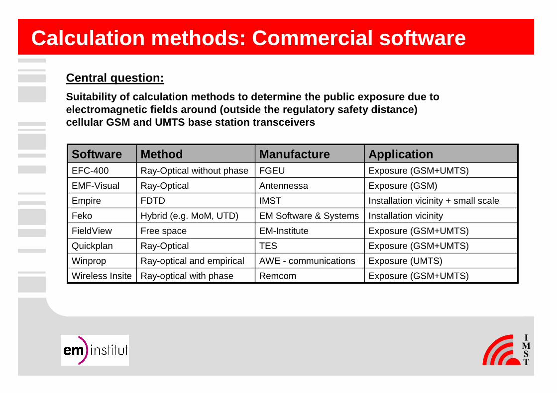
Calculation methods: Commercial software
Exposure (GSM+UMTS)EM-InstituteFree spaceFieldView
Exposure (GSM+UMTS)RemcomRay-optical with phaseWireless Insite
Exposure (UMTS)AWE - communicationsRay-optical and empiricalWinprop
Exposure (GSM+UMTS)TESRay-OpticalQuickplan
Installation vicinityEM Software & SystemsHybrid (e.g. MoM, UTD)Feko
Installation vicinity + small scaleIMST FDTDEmpire
Exposure (GSM)AntennessaRay-OpticalEMF-Visual
Exposure (GSM+UMTS)FGEURay-Optical without phaseEFC-400
ApplicationManufactureMethodSoftware
Central question:
Suitability of calculation methods to determine the public exposure due to electromagnetic fields around (outside the regulato ry safety distance) cellular GSM and UMTS base station transceivers

0
45
90
135
180
225
270
315
0,01
0,1
0,1
1
1
-90 -80 -70 -60 -50 -40 -30 -20 -10 0 10 20 30 40 50 60 70 80 90-35
-30
-25
-20
-15
-10
-5
0
5
10
15
20
Antenna pattern
-90 -80 -70 -60 -50 -40 -30 -20 -10 0 10 20 30 40 50 60 70 80 90-35
-30
-25
-20
-15
-10
-5
0
5
10
15
20D
irect
ivity
[dB
i]
Dire
ctiv
ity [d
Bi]
1. Dependency on frequency 2. Dependency on electr. downtilt
Angle [degrees] Angle [degrees]
3. Dependency on installation vicinity

Antenna pattern: Synthesis
0
45
90
135
180
225
270
315
-50
-40
-40
-30
-30
-20
-20
-10
-10-50-50
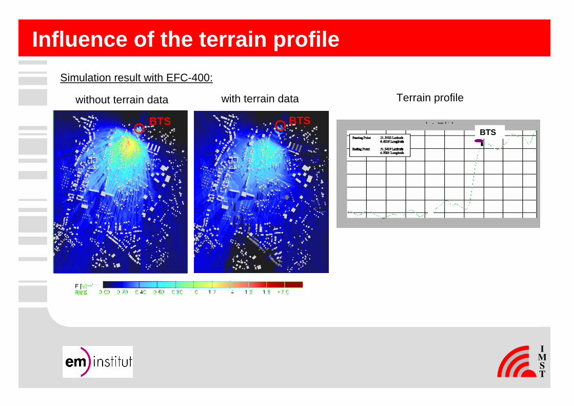
Influence of the terrain profile
BTS
without terrain data with terrain data
Simulation result with EFC-400:
Terrain profile
BTSBTS

Building informationBlack-White picture from land registerSatellite picture
Import in Winprop and Quickplan
� Cooperation with land surveying office NRW

Building information: „Vectorisation“
Vectorising the black building shapes Import in EFC-400
Generate 3rd dimension
Import in Wireless Insite
„Corel Draw“
„Autocad“
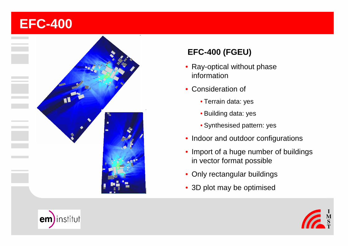
EFC-400
EFC-400 (FGEU)
• Ray-optical without phase information
• Consideration of
• Terrain data: yes
• Building data: yes
• Synthesised pattern: yes
• Indoor and outdoor configurations
• Import of a huge number of buildings in vector format possible
• Only rectangular buildings
• 3D plot may be optimised
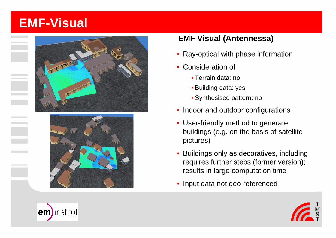
EMF-VisualEMF Visual (Antennessa)
• Ray-optical with phase information
• Consideration of
• Terrain data: no
• Building data: yes
• Synthesised pattern: no
• Indoor and outdoor configurations
• User-friendly method to generate buildings (e.g. on the basis of satellite pictures)
• Buildings only as decoratives, including requires further steps (former version);results in large computation time
• Input data not geo-referenced
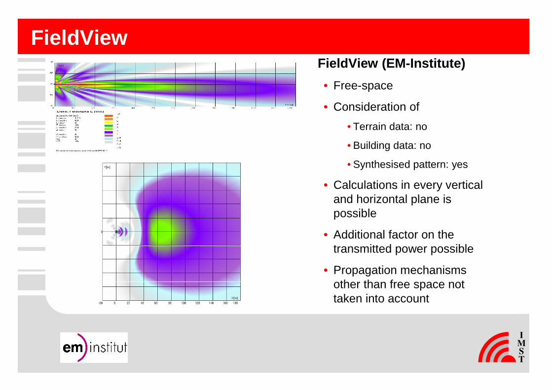
FieldViewFieldView (EM-Institute)
• Free-space
• Consideration of
• Terrain data: no
• Building data: no
• Synthesised pattern: yes
• Calculations in every vertical and horizontal plane is possible
• Additional factor on the transmitted power possible
• Propagation mechanisms other than free space not taken into account
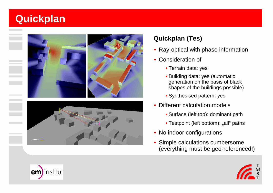
Quickplan
Quickplan (Tes)
• Ray-optical with phase information
• Consideration of• Terrain data: yes
• Building data: yes (automatic generation on the basis of black shapes of the buildings possible)
• Synthesised pattern: yes
• Different calculation models
• Surface (left top): dominant path
• Testpoint (left bottom): „all“ paths
• No indoor configurations
• Simple calculations cumbersome(everything must be geo-referenced!)
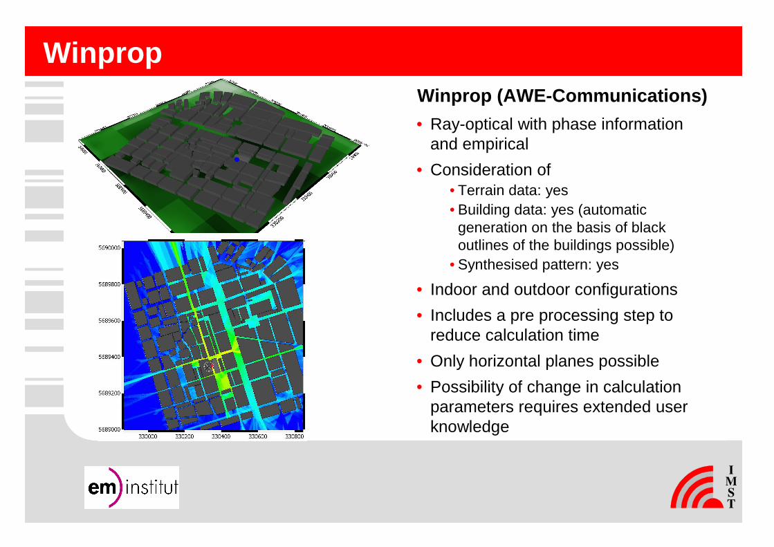
WinpropWinprop (AWE-Communications)
• Ray-optical with phase information and empirical
• Consideration of• Terrain data: yes• Building data: yes (automatic
generation on the basis of black outlines of the buildings possible)
• Synthesised pattern: yes
• Indoor and outdoor configurations
• Includes a pre processing step to reduce calculation time
• Only horizontal planes possible
• Possibility of change in calculation parameters requires extended user knowledge
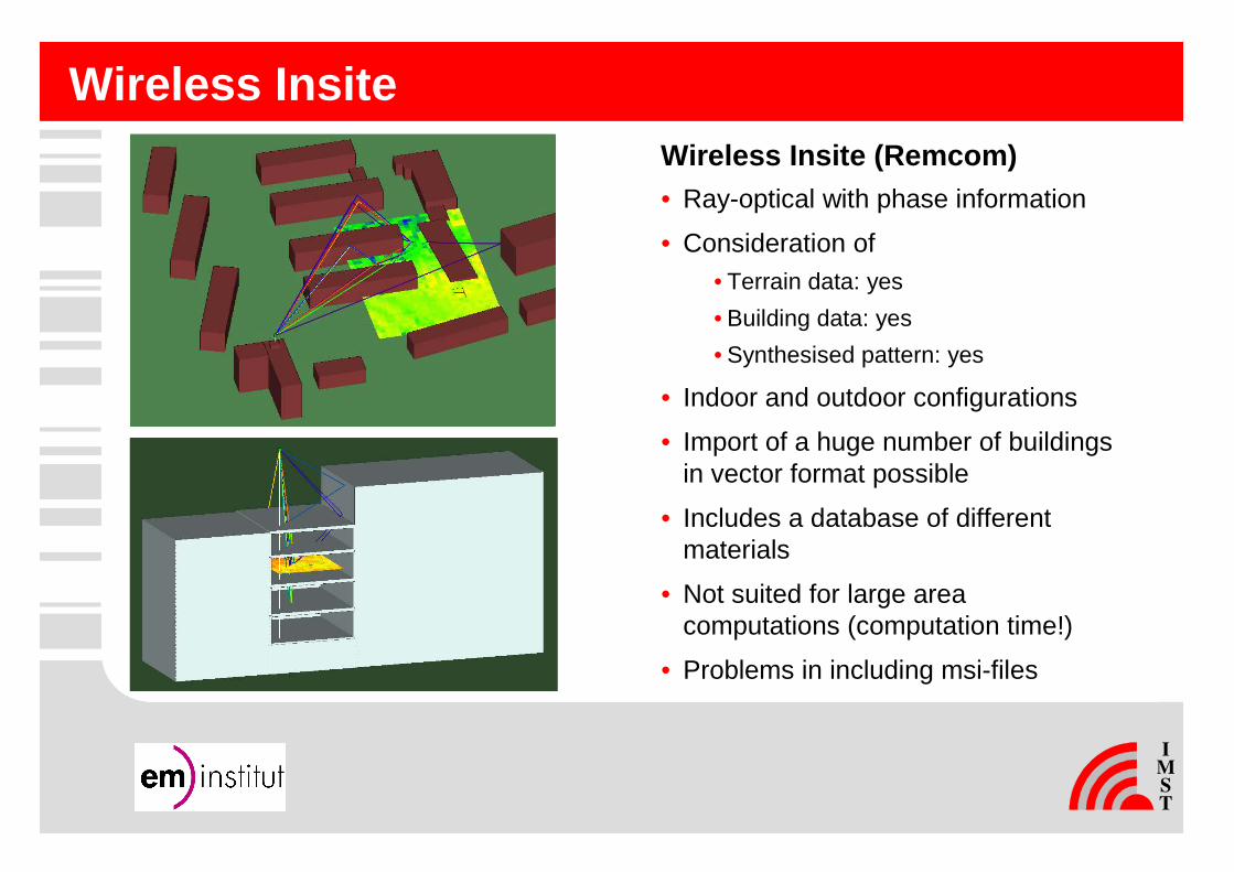
Wireless InsiteWireless Insite (Remcom)• Ray-optical with phase information
• Consideration of• Terrain data: yes
• Building data: yes
• Synthesised pattern: yes
• Indoor and outdoor configurations
• Import of a huge number of buildings in vector format possible
• Includes a database of different materials
• Not suited for large area computations (computation time!)
• Problems in including msi-files
-10
-5
0
5
10
15
20
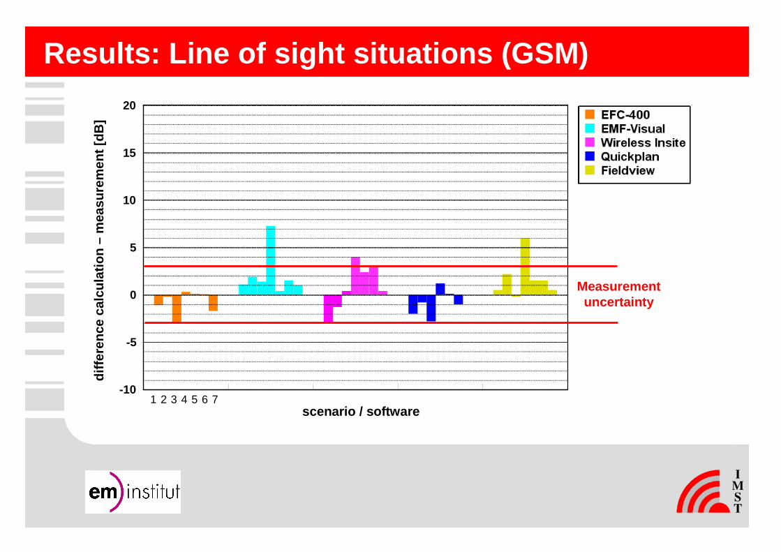
Results: Line of sight situations (GSM)
Measurementuncertainty
diffe
renc
e ca
lcul
atio
n –
mea
sure
men
t [dB
]
scenario / software1 2 3 4 5 6 7

1 2 3 4 5 6 7 8 9 10 11-10
0
10
20
30
40
50
60
70
Results: Non line of sight situations (UMTS)
Measurementuncertainty
below antenna
diffe
renc
e ca
lcul
atio
n –
mea
sure
men
t [dB
]
scenario / software

Outlook: Application of results
Project: Investigation of sleep quality in persons living near a mobile base station – Experimental study on the evaluation of possible psychological and physiological effects under residential conditions(Management: Charite – Universitätsmedizin Berlin)
Objective: - study of diverse sleep parameters in groups near BTS- double blind study- artificial mobile phone base station signal- measurement of exposure: artificial base station,other base stations, other RF exposure
- 60 persons x 6 base station sites