Embed Size (px)
Citation preview

Workshop on Optical LEO Downlinks
Institute of Communications an Navigation German Aerospace Center
10th November 2016

The Transmission Scenario in Optical LEO Downlinks OLEODL-Workshop, DLR-IKN, 10th November 2016 Dirk Giggenbach
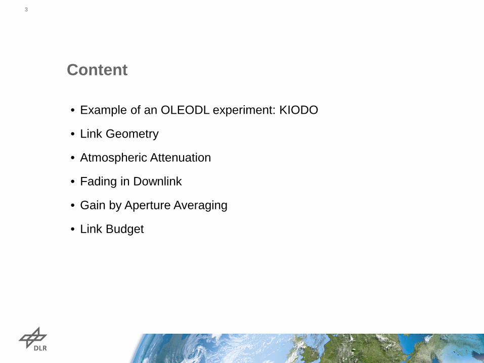
Content
• Example of an OLEODL experiment: KIODO
• Link Geometry
• Atmospheric Attenuation
• Fading in Downlink
• Gain by Aperture Averaging
• Link Budget
3
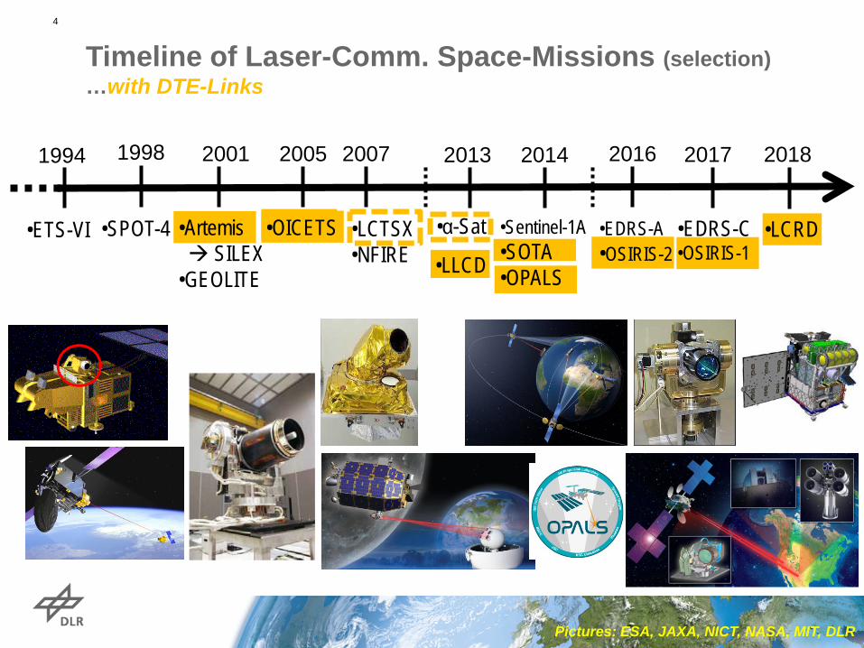
Timeline of Laser-Comm. Space-Missions (selection) …with DTE-Links
2017
•EDRS-C •OSIRIS-1
2013
•α-Sat
•LLCD
2005
•OICETS
2007
•LCTSX •NFIRE
1998
•SPOT-4
2001
•Artemis SILEX •GEOLITE
Pictures: ESA, JAXA, NICT, NASA, MIT, DLR
•ETS-VI
1994 2016
•EDRS-A •OSIRIS-2
2014
•Sentinel-1A •SOTA •OPALS
2018
•LCRD
4

• Cooperation between DLR and JAXA/NICT • Measurement Campaigns in 2006 & 2009 • Channel Characterization:
• Intensity Scintillation and Wavefront-Distortions • Communication Performance by the Bit Error Ratio
KIODO: Kirari Optical Downlinks to Oberpfaffenhofen
5

• Knowledge of Orbit allows open-
loop pointing of OGS‘s Beacon
• Satellite Terminal‘s extended FoV
detects beacon
• Reorientation/Pointing of Downlink
Signal from Satellite
• Data signal also allows precise
tracking at OGS
• Link is terminated at low elevation
Phases of a OLEO Down-Link
6

Typical LEO-DTE Link Geometry Low and High LEO orbit
Orbit: Distance at 5° max. link duration 5°
Sat-Velocity slew-rate at zenith
point-ahead (polar orbit)
400km circular 1804 km 475 s 7.67 km/s 1.1 °/s 51 µrad
900km circular 2992 km 831 s 7.40 km/s 0.48 °/s 49 µrad
7
DTE: Direct-to-Earth

Typical LEO-DTE Elevation Distribution
20%
25%
25%
Normalized Cumulative
500km orbit
Giggenbach, Moll, Fuchs, de Cola, Mata-Calvo, “SPACE COMMUNICATIONS PROTOCOLS FOR FUTURE OPTICAL SATELLITE-DOWNLINKS”, IAC 2011
8

Atmospheric Transmission Coefficient: Detail NIR
Coefficient at various altitudes
9

Scintillating Signal over Elevation
into 40cm OGS-aperture KIODO-2006, 847nm
10

Aperture Averaging in OLEODL: 2 Aperture sizes
power into 5cm:
…same pass: power into 40cm
11
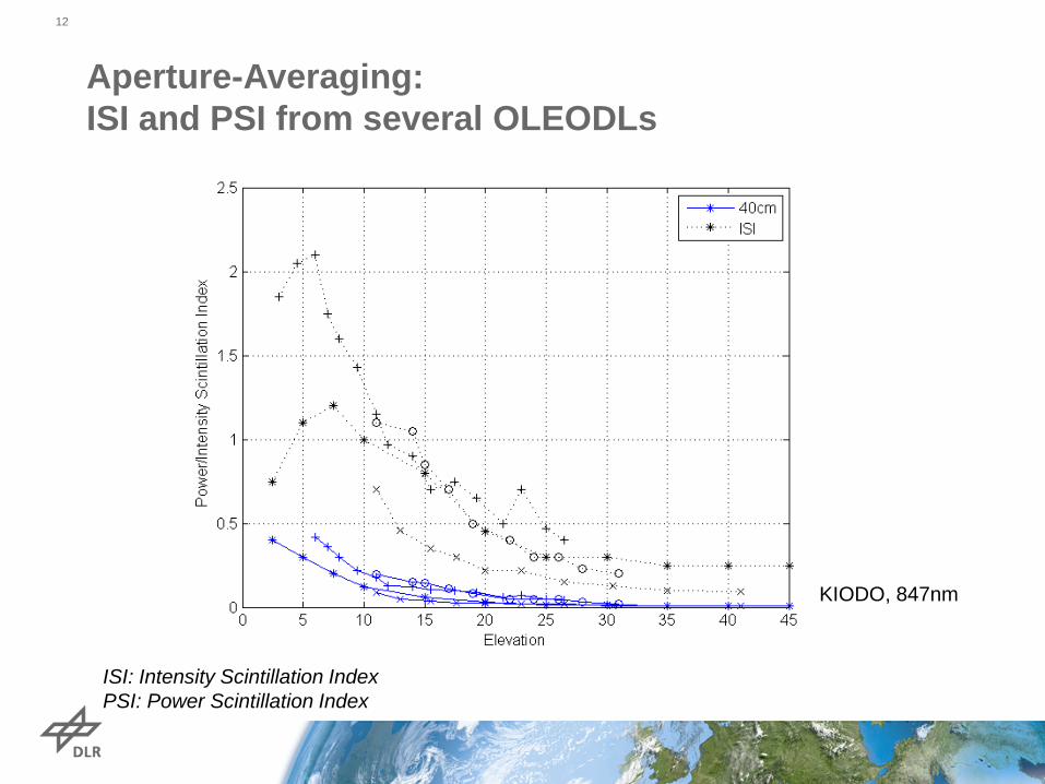
Aperture-Averaging: ISI and PSI from several OLEODLs
12
KIODO, 847nm
ISI: Intensity Scintillation Index PSI: Power Scintillation Index

Aperture Averaging: Scintillation-“Gain“
…with lognormal fading:
13
~9dB
~6dB
Example: 847nm
( )2scint ,I aperturea f Dσ=

Parameter unit 5° 10° 15° 20° 5° 10° 15° 20°mean modulated signal pow er W 1.00 1.00 1.00 1.00 1.00 1.00 1.00 1.00optical Tx loss dB -1.49 -1.49 -1.49 -1.49 -1.49 -1.49 -1.49 -1.49Tx-divergence FWHM mrad 0.04 0.04 0.04 0.04 0.04 0.04 0.04 0.04Tx-divergence 1/e² (full angle) mrad 0.07 0.07 0.07 0.07 0.07 0.07 0.07 0.07Tx-telescope gain dB 98.19 98.19 98.19 98.19 98.19 98.19 98.19 98.19Pointing Penalty dB -3.01 -3.01 -3.01 -3.01 -3.01 -3.01 -3.01 -3.01
data rate Gbps 2.50 10.00 10.00 10.00 1.00 5.00 10.00 10.00Wavelength nm 1550.00 1550.00 1550.00 1550.00 1550.00 1550.00 1550.00 1550.00Modulation Format - IM/DD IM/DD IM/DD IM/DD IM/DD IM/DD IM/DD IM/DDBit Error Rate - 1.0E-06 1.0E-06 1.0E-06 1.0E-06 1.0E-06 1.0E-06 1.0E-06 1.0E-06Receiver Sensitivity @ BER Ph/Bit 800.00 800.00 800.00 800.00 800.00 800.00 800.00 800.00
link distance km 1804.00 1439.00 1175.00 984.00 2992.00 2568.00 2224.00 1947.00Free-space loss dB -263.30 -261.34 -259.58 -258.04 -267.70 -266.37 -265.12 -263.96Scintillation Loss dB -5.00 -3.50 -2.50 -1.70 -5.00 -3.50 -2.50 -1.70Atmospheric attenuation dB -8.00 -4.00 -3.00 -2.00 -8.00 -4.00 -3.00 -2.00
Aperture Diameter cm 60.00 60.00 60.00 60.00 60.00 60.00 60.00 60.00Rx telescope gain (ideal) dB 121.70 121.70 121.70 121.70 121.70 121.70 121.70 121.70Loss due to secondary mirror dB -0.28 -0.28 -0.28 -0.28 -0.28 -0.28 -0.28 -0.28Optical Rx Losses dB -6.02 -6.02 -6.02 -6.02 -6.02 -6.02 -6.02 -6.02Rx-Pow er after Losses dBm -37.21 -29.75 -25.98 -22.64 -41.60 -34.78 -31.53 -28.57
Splitting Ratio to Comm Sensor dB -0.46 -0.46 -0.46 -0.46 -0.46 -0.46 -0.46 -0.46Tracking/Coupling Loss dB -0.97 -0.97 -0.97 -0.97 -0.97 -0.97 -0.97 -0.97Rx-pow er onto comm-detector dBm -38.64 -31.17 -27.41 -24.07 -43.03 -36.20 -32.95 -30.00Coding Gain dB 3.98 3.98 3.98 3.98 3.98 3.98 3.98 3.98
Eff. rx pow er on comm-detectior (incl. Coding) -34.66 -27.19 -23.43 -20.09 -39.05 -32.22 -28.97 -26.02Required Pow er (Rx-sensitivity) dBm -35.91 -29.89 -29.89 -29.89 -39.89 -32.90 -29.89 -29.89Communication Margin dB 1.3 2.7 6.5 9.8 0.8 0.7 0.9 3.9
Rx
400 km Orbit 900 km OrbitTx
Cha
nnel
Com
m.
Syst
emC
omm
s
Typical Link Budgets for 400km and 900km orbit height 14

Summary
• One single OLEODL pass shows extreme static variation over elevation ~15dB
• Additional dynamic variation due to IRT (scintillation) ~10dB
• Aperture Averaging with multimode receivers allows mitigation of IRT ~8dB
• 10 Gbps are practical above 15° elevation
• 10 Years of Experiments and Demonstrations paved the way towards operational use
15

Workshop on Optical LEO Downlinks
Institute of Communications an Navigation German Aerospace Center
10th November 2016