Embed Size (px)
Citation preview

WORKSHOP
ON “LECTURES AND VIRTUAL PRACTICAL DEMONSTRATION”
DR. RAJESH MATHPAL
SCHOOL OF SCIENCES
UTTARAKHAND OPEN UNIVERSITY
TEENPANI, HALDWANI
UTTRAKHAND
MOB:9758417736,7983713112
Email: [email protected]
INTEREFERENCE OF LIGHT In 1680 Huygens proposed the wave theory of light. But at that time, it was not clear about the nature of light wave, its speed and way of propagation. In 1801 Thomas Young performed an experiment called Young’s double slit experiment and noticed that bright and dork fringes are formed which is called inference pattern. At that time it was a surprising phenomenon and is to be explained.
After the Maxwell’s electromagnetic theory it was cleared that light is an electromagnetic wave. In physics, interference is a phenomenon in which two waves superimpose on each other to form a resultant wave of greater or lower or of equal amplitude. When such two waves travel in space under certain conditions the intensity or energy of waves are redistributed at certain points which is called interference of light and we observe bright and dark fringes.
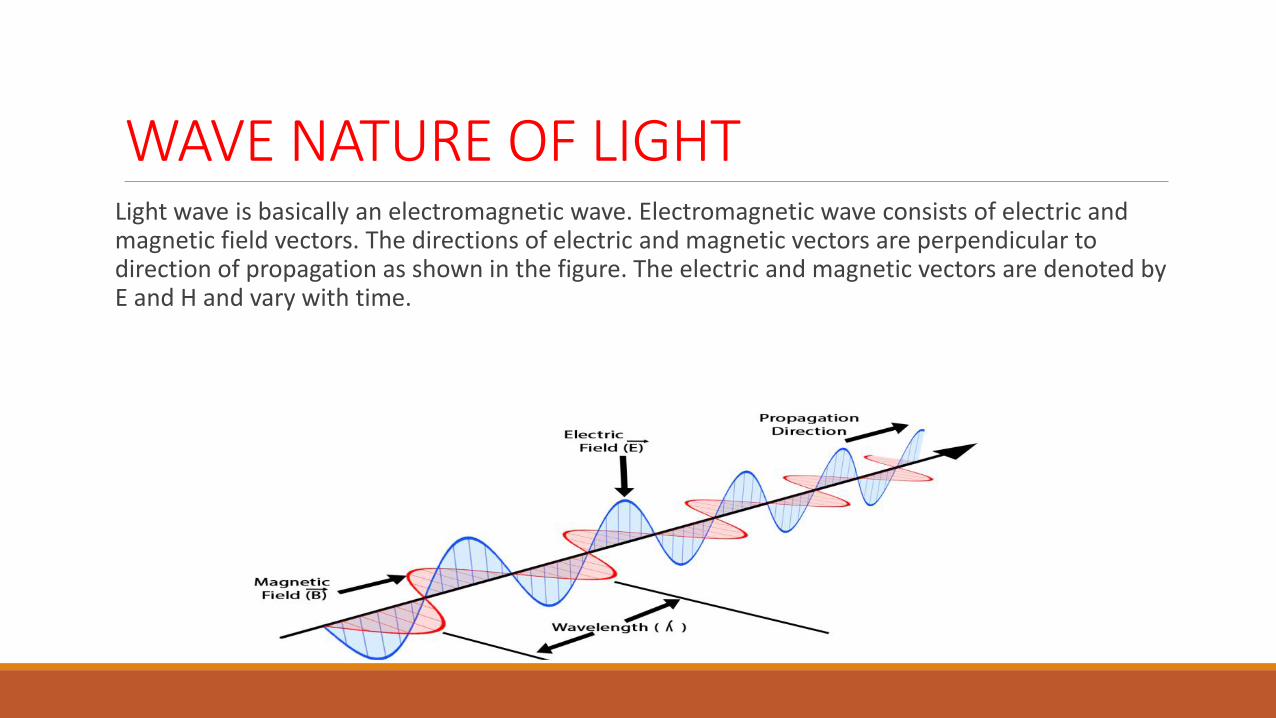
WAVE NATURE OF LIGHT Light wave is basically an electromagnetic wave. Electromagnetic wave consists of electric and magnetic field vectors. The directions of electric and magnetic vectors are perpendicular to direction of propagation as shown in the figure. The electric and magnetic vectors are denoted by E and H and vary with time.
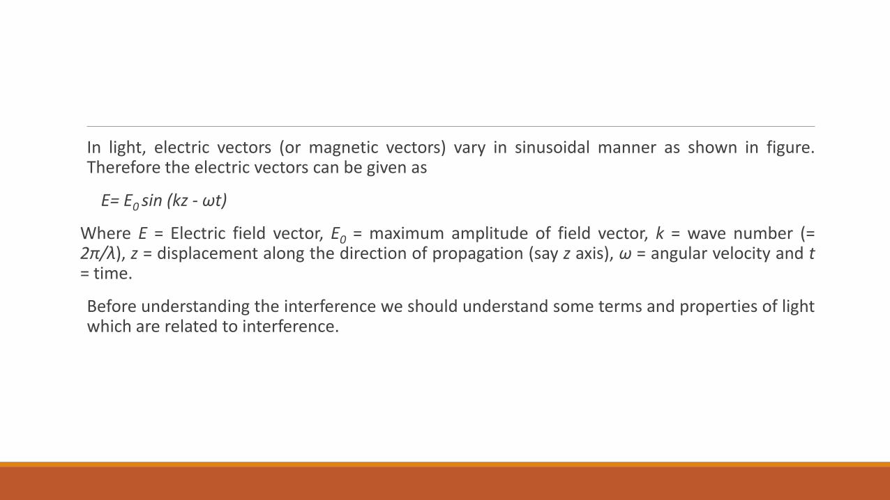
In light, electric vectors (or magnetic vectors) vary in sinusoidal manner as shown in figure. Therefore the electric vectors can be given as
E= E0 sin (kz - ωt)
Where E = Electric field vector, E0 = maximum amplitude of field vector, k = wave number (= 2π/λ), z = displacement along the direction of propagation (say z axis), ω = angular velocity and t = time.
Before understanding the interference we should understand some terms and properties of light which are related to interference.
Monochromatic Light The visible light is a continuous spectrum which consist a large number of wavelengths (approximately 3500Å to 7800Å). Every single wavelength (or frequency) of this continuous spectrum is called monochromatic light. However, the individual wavelengths are sufficiently close and indistinguishable. Some time we consider very narrow band of wave lengths as monochromatic light.
Ordinary light or white light, coming from sun, electric bulb, CFL, LED etc. consists a large number of wave lengths and hence non-monochromatic. But some specific sources like sodium lamp and helium neon laser emit monochromatic lights with wave lengths 589.3 nm and 632.8 nm respectively. It should be noted that sodium lamp, actually emits two spectral lines of wavelengths 589.0 nm and 589.6 nm which are very close together, and source is to be consider monochromatic.
Phase Difference and Coherence
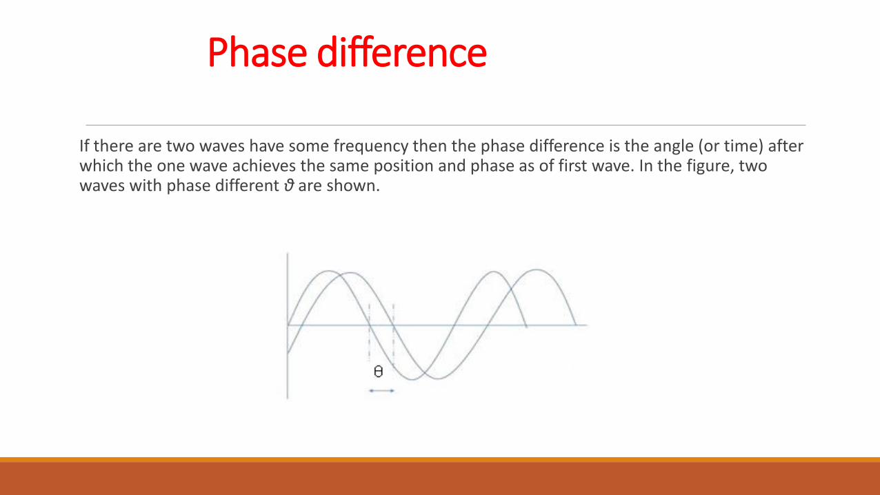
Phase difference
If there are two waves have some frequency then the phase difference is the angle (or time) after which the one wave achieves the same position and phase as of first wave. In the figure, two waves with phase different θ are shown.
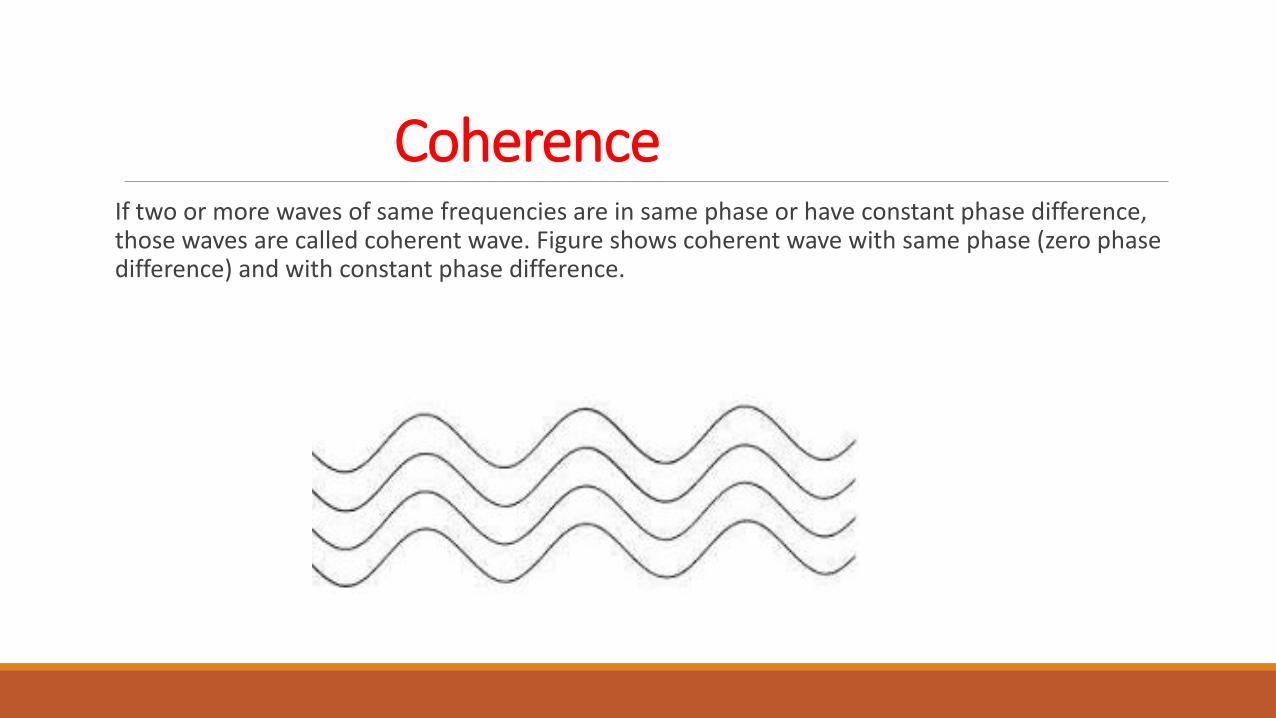
Coherence If two or more waves of same frequencies are in same phase or have constant phase difference, those waves are called coherent wave. Figure shows coherent wave with same phase (zero phase difference) and with constant phase difference.

Optical path and Geometric Path
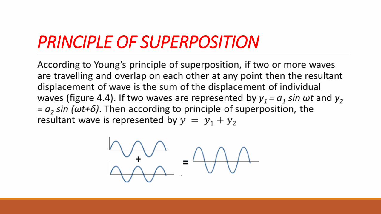
PRINCIPLE OF SUPERPOSITION
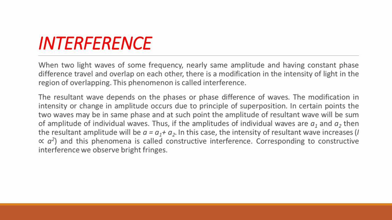
INTERFERENCE
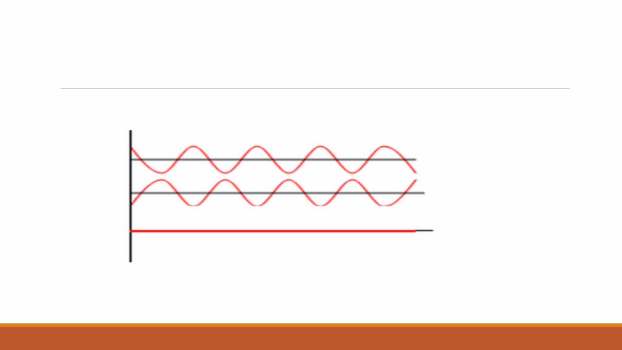
On the other hand, at certain points the two waves may be in opposite phase as shown in figure. In these points the resultant amplitude of waves will be sum of amplitude of individual waves with opposite directions. If the amplitudes of individual waves are a1 and a2 then the resultant amplitude will be a = a1- a2 and the intensity of resultant wave will be minimum. This case is called destructive interference. Corresponding to such points we observe dark fringes. Figure depicts two waves of opposite phase and their resultant.
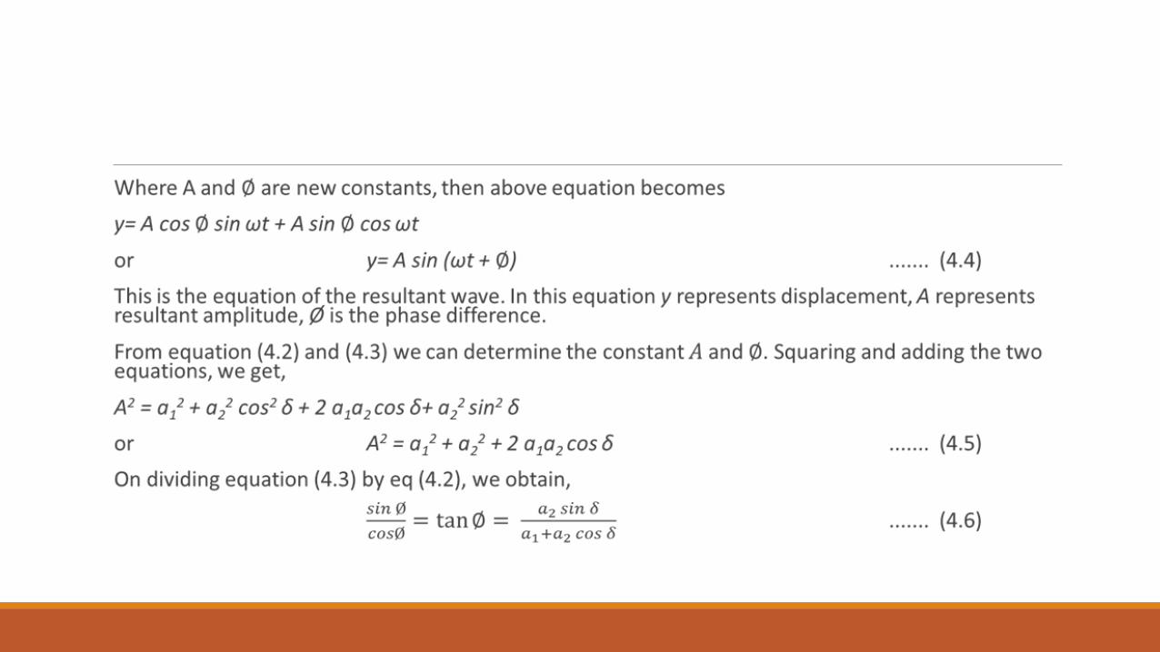
Theory of Superposition
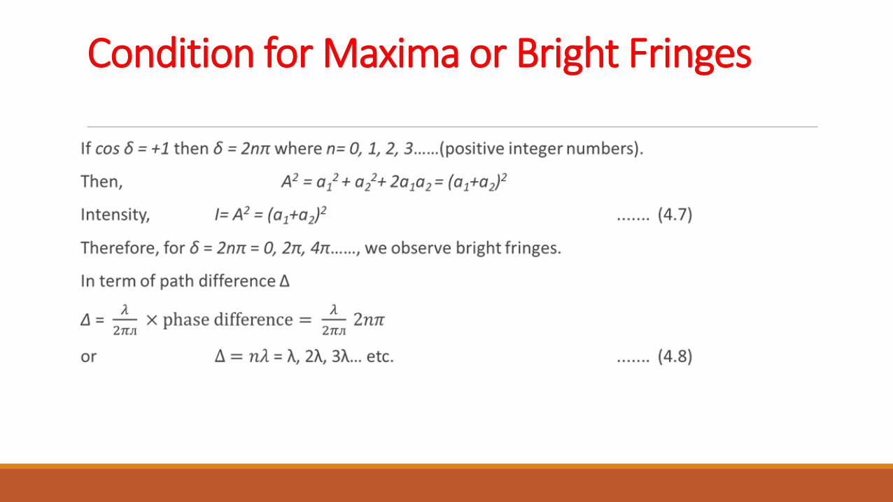
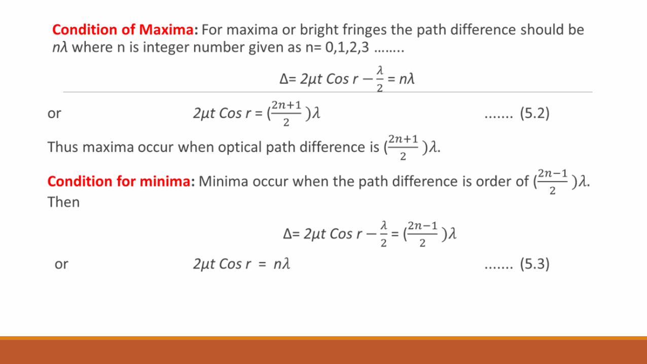
Condition for Maxima or Bright Fringes
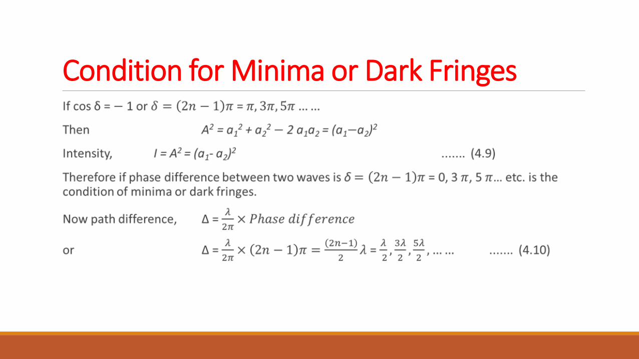
Condition for Minima or Dark Fringes
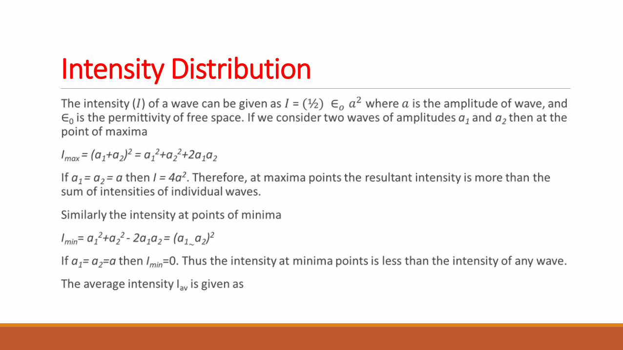
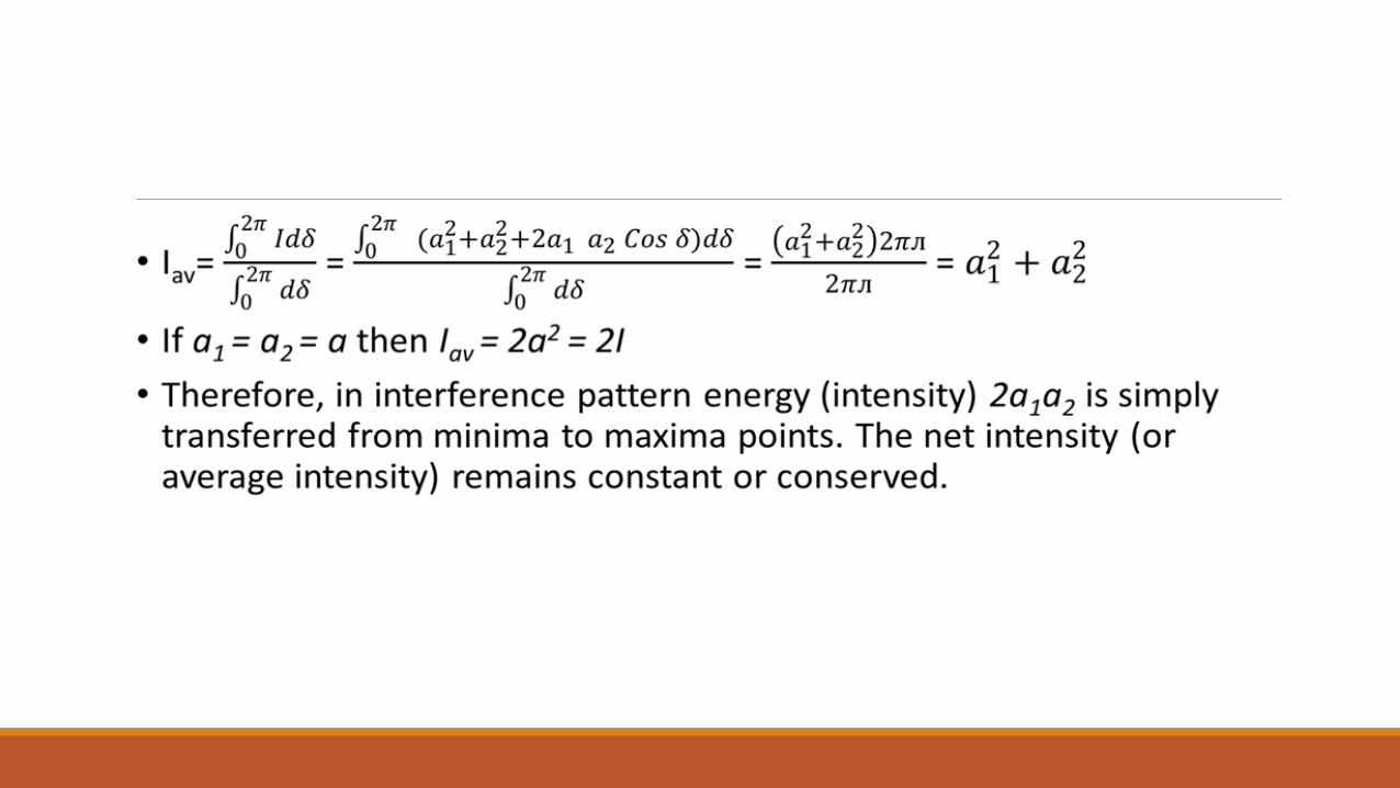
Intensity Distribution
CLASSIFICATION OF INTERFERENCE The interference can be divided into two categories.
Division of Wavefront
In this class of interference, the wave front originating from a common source is divided into two parts by employing mirror, prisms or lenses on the path. The two wave front thus separated traverse unequal paths and are finally brought together to produce interference pattern. Examples are biprism, Lloyd’s mirror, Laser etc.
Division of Amplitude
In this class of interference the amplitude or intensity of incoming beam divided into two or more parts by partial reflection and refraction. Examples are thin films, Newton’s rings, Michelson interferometer etc.
YOUNG’S DOUBLE SLIT EXPERIMENT In 1801, Thomas Young performed double slit experiment in which a light first entered through a pin holes, then again divided into two pinholes and finally brought to superimpose on each other and obtained interferences. Young’s performed experiment with sum light. Now the experiments are modified with monochromatic light and efficient slits.
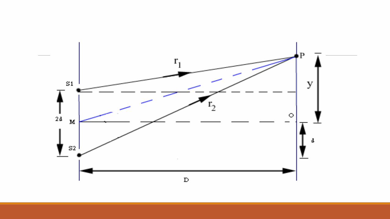
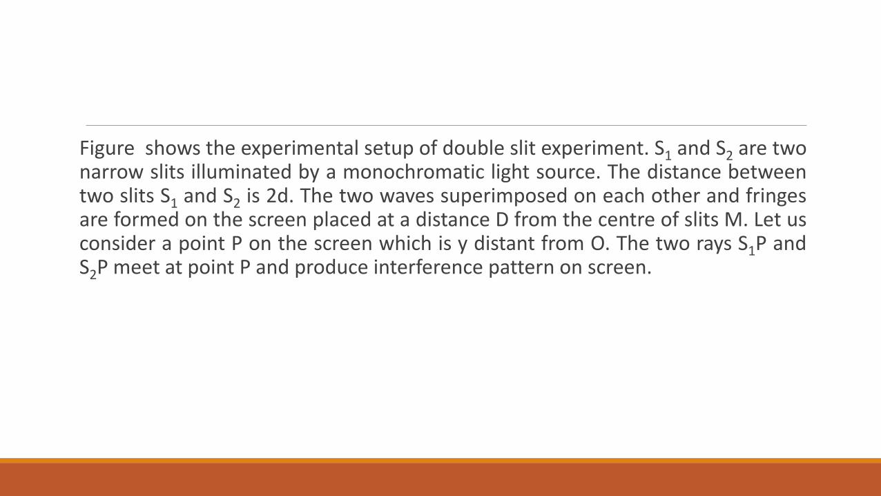
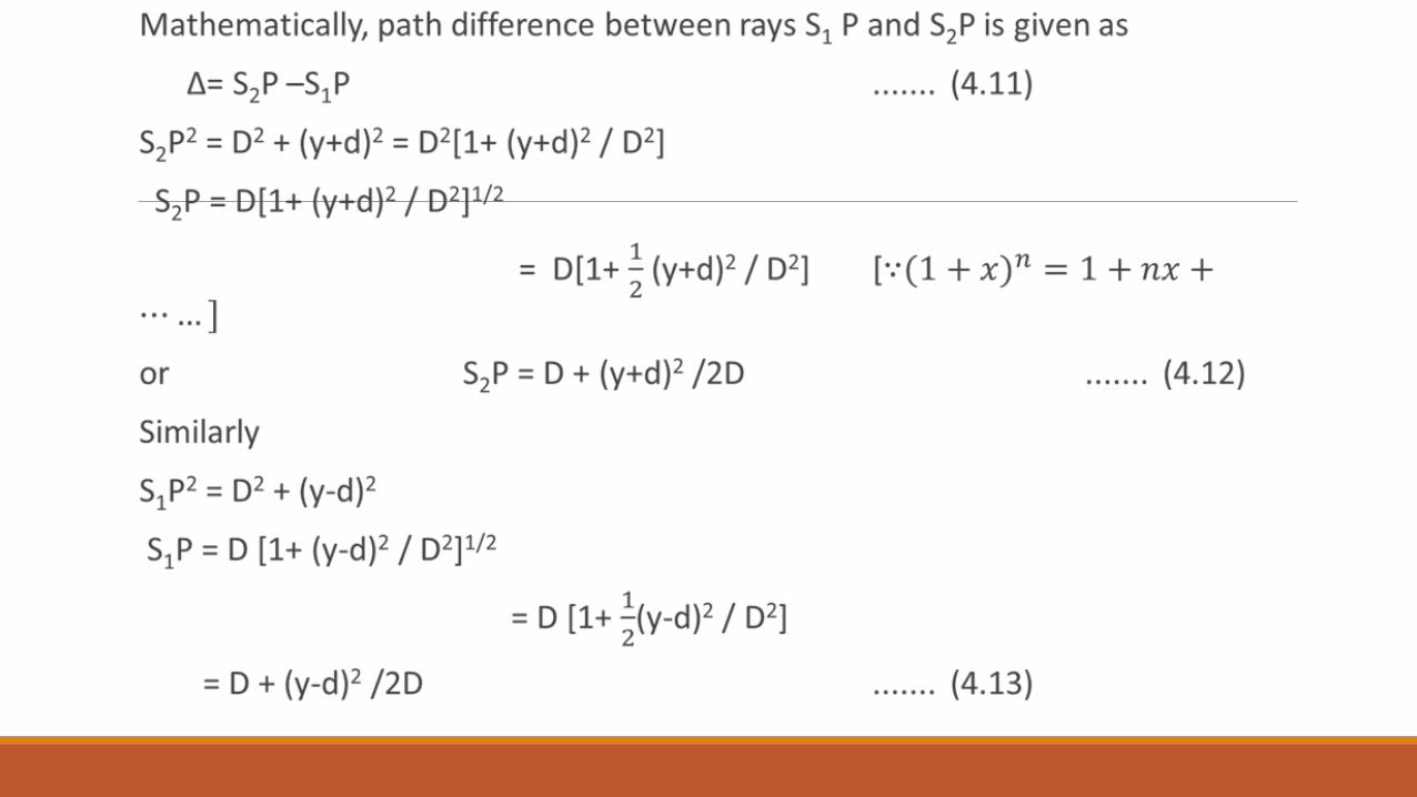
Figure shows the experimental setup of double slit experiment. S1 and S2 are two narrow slits illuminated by a monochromatic light source. The distance between two slits S1 and S2 is 2d. The two waves superimposed on each other and fringes are formed on the screen placed at a distance D from the centre of slits M. Let us consider a point P on the screen which is y distant from O. The two rays S1P and S2P meet at point P and produce interference pattern on screen.
COHERENCE LENGTH AND COHERENCE TIME
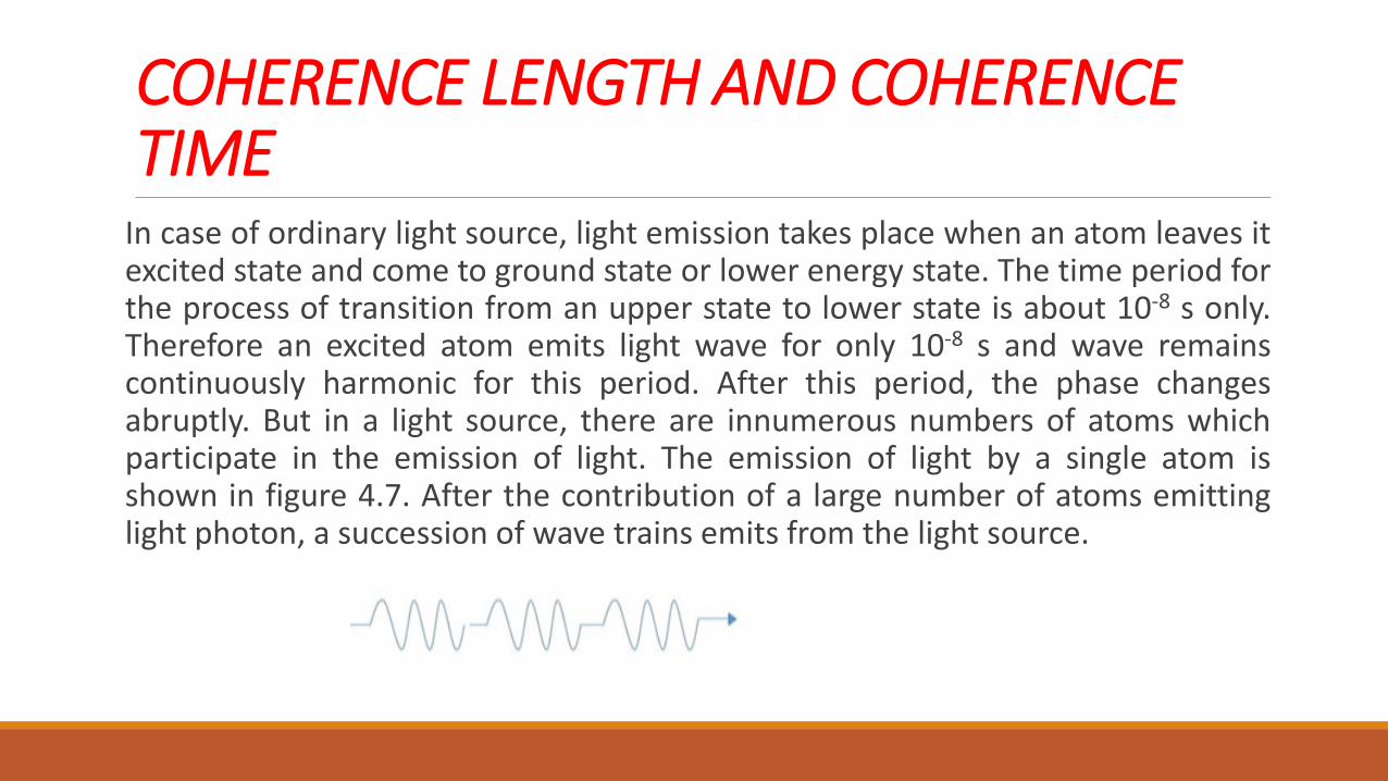
In case of ordinary light source, light emission takes place when an atom leaves it excited state and come to ground state or lower energy state. The time period for the process of transition from an upper state to lower state is about 10-8 s only. Therefore an excited atom emits light wave for only 10-8 s and wave remains continuously harmonic for this period. After this period, the phase changes abruptly. But in a light source, there are innumerous numbers of atoms which participate in the emission of light. The emission of light by a single atom is shown in figure 4.7. After the contribution of a large number of atoms emitting light photon, a succession of wave trains emits from the light source.
Coherence Length Coherence length is propagation distance over which a coherent wave maintains coherence. If the path of the interfering waves or path different is smaller than coherent length, the interference is sustainable and we observe distinct interference pattern.
Coherence Time Coherent time τc is defined as the average time period during which the wave remains sinusoidal and after which the phase change abruptly.
CONDITIONS FOR SUSTAINABLE INTERFERENCE
As we studied the different aspects of interference it is clear that under which conditions interference can take place. But for strong interference or sustained interference some more condition may be summarized. The conditions are:
The interfering waves must have same frequencies. For this purpose we can select a single source.
The interfering waves must be coherent. To maintain the coherence, the path difference of two interfering waves must be less than coherence length.
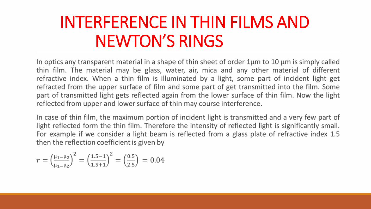
INTERFERENCE IN THIN FILMS AND NEWTON’S RINGS
Thus only 4% of incident light is reflected by the upper surface of glass film and 96% of light is transmitted into the glass plate. Similarly nearly 4% of light is again reflected through the lower surface of glass plate. If we consider the interference due to the light reflected from upper and lower surface of glass plate, the intensity of light will be significantly small.
When white light is incident of thin film, interference pattern is appeared as colourful bands since white light consists different wavelengths, different wavelengths produce interference bands of different colours and thicknesses. Interference in thin films also occurs in nature. Thin wings of many insects and butterflies are layer of thin films. There thin films are responsible for structural colourization which produce different colours by microscopically structured surface, and suitable enough for interference of light.
INTERFERENCE DUE TO PLANE PARALLEL THIN FILM
A plane parallel thin film is transparent film of uniform thickness with two parallel reflecting surfaces. The example is a thin glass film. Light wave generally suffers multiple reflections and refractions at the two surfaces. There are two cases of interference as given below
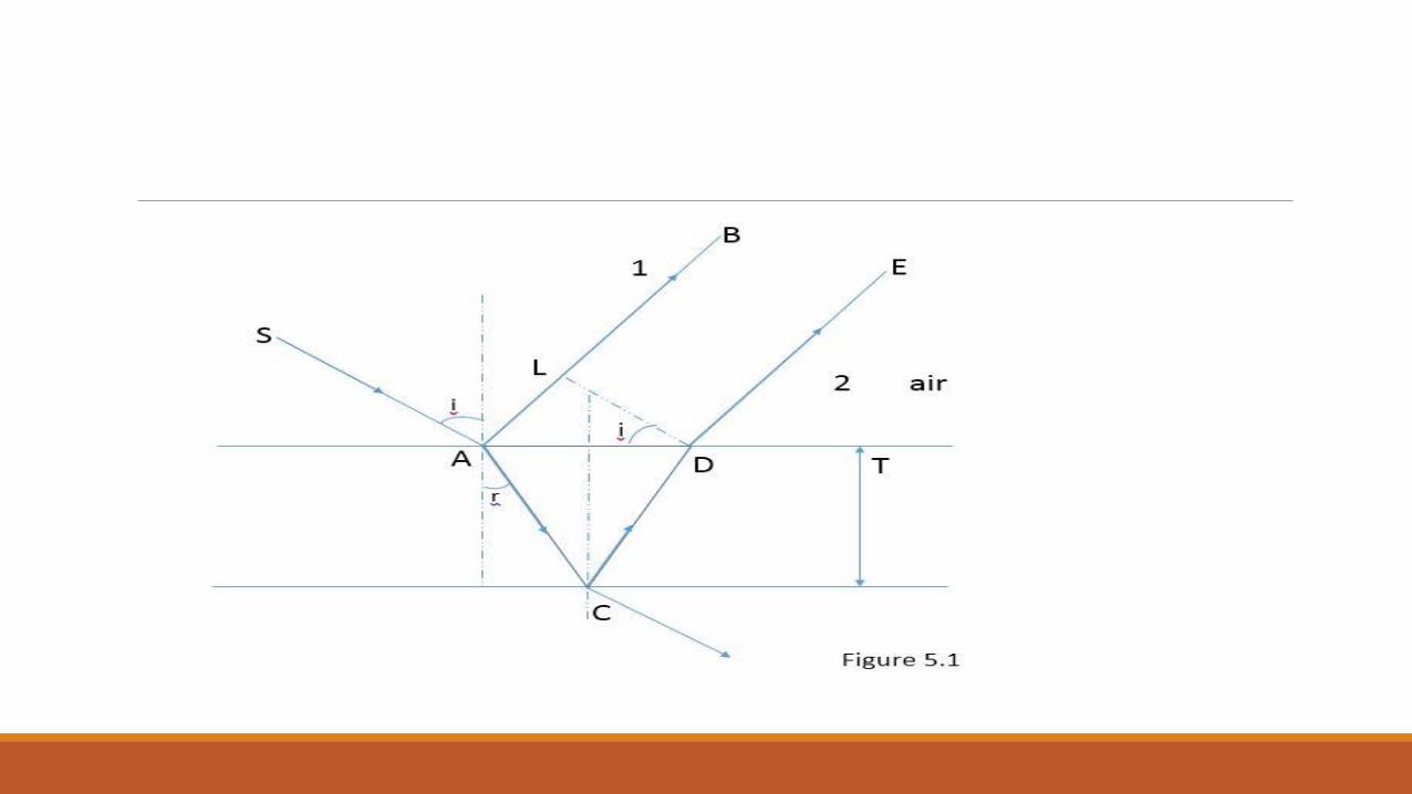
Interference in Case of Reflected Light Let us consider a thin film of thickness t as shown in figure. A monochromatic light ray SA is incident on a thin film with an angle of incident i as shown in figure. The film is made of a transparent material (say glass) of refractive index µ. Some part of light ray reflected at point A along the direction AB and some part of light transmitted into the film along AC direction. The ray AC makes an angle of refraction r at point A, and the angle r becomes angle of incident ACN at point C. Some part of light of ray AC again reflected in the direction CD which comes out from the film along the direction DE. The light rays AB and DE come together and they can produced interference pattern on superposition.
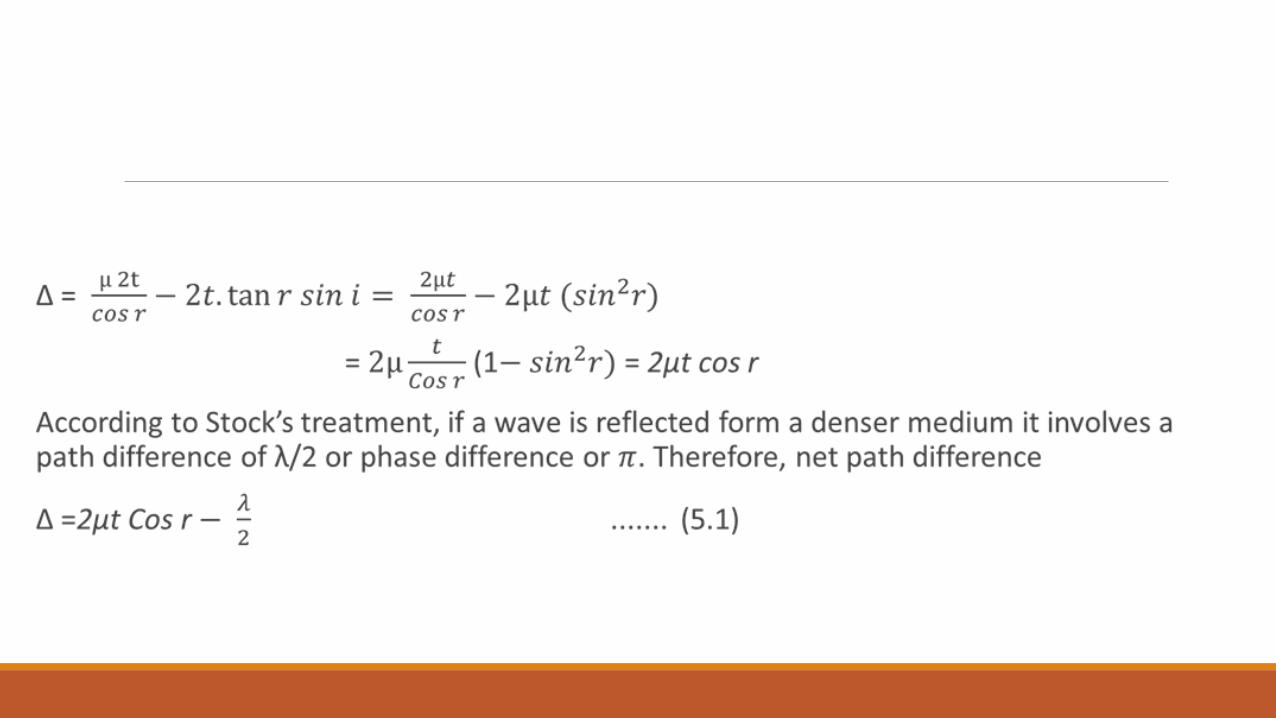
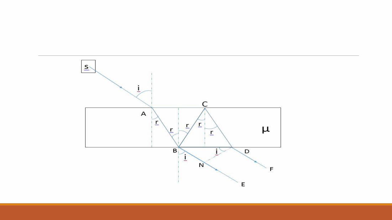
Interference in Case of Refracted Light A light ray SA is incident at point A on a film of refractive index as shown in figure 5.2. Some part of light ray reflected at point A and some part of light transmitted into the film along AB. In case of interference due to refracted light we are not interested in the reflected light. At point B some part of light is again reflected along direction BC, then again reflected at point C and finally refracted at point D and comes out form the medium along DF direction. Now the light rays coming along BE and DF are coherent and can produce interference pattern in the region of superposition.
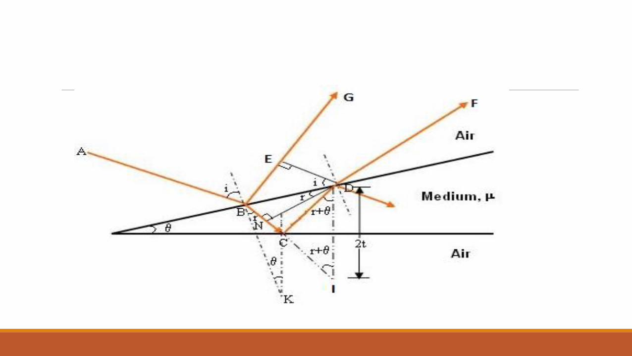
INTERFERENCE IN A WEDGE SHAPED FILM In a wedge shape film, the thickness of the film at one end is zero and it increases consistently towards another end. A glass wedge shaped film is shown in figure. Similarly a wedge shaped air film can be formed by using two glass films touch at one end and separated by a thin wire at another end.
NEWTON’S RINGS
Newton’s rings in a special case of wedge shaped film in which an air film is formed between a glass plate and a convex surface of lens. The thickness of air film is zero at the center and increases gradually towards the outside.
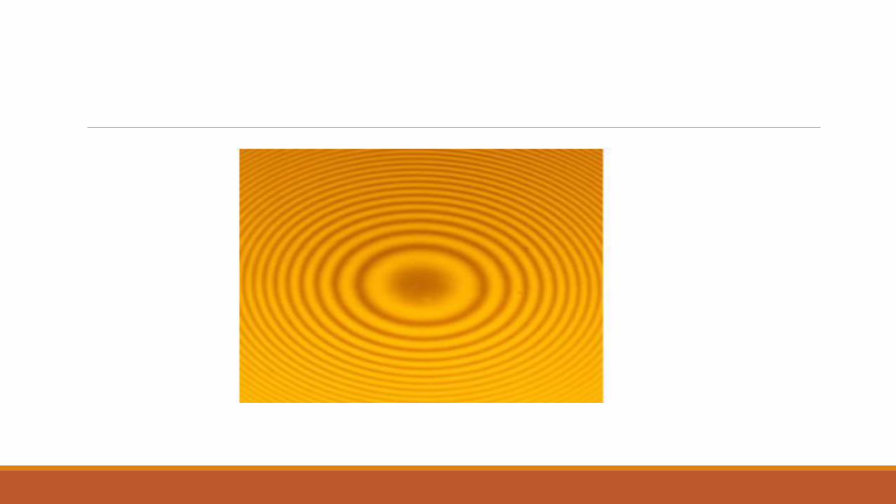
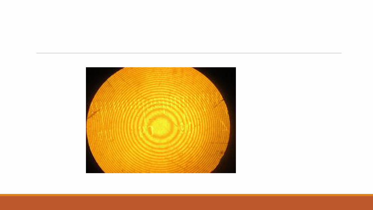
When a plano-convex lens of large focal length is placed on a plane glass plate, a thin air film is formed between the lower surface of plano-convex lens and upper surface of glass plate. When a monochromatic light falls on this film the light reflected from upper and lower surfaces of air film, and after interference of these rays, we get an inner dark spot surrounded by alternate bright and dark rings called Newton’s rings. These rings are first observed by Newton and hence called Newton’s rings.
Experimental Arrangement for Reflected Light
The experimental arrangement for Newton’s rings experiment is shown in Figure. A beam of light from a monochromatic source S is made parallel by using a convex lens L. The parallel beam of light falls on a partially polished glass plate inclined at an angle of 450. The light falls on glass plate is partially reflected and partially transmitted. The reflected light normally falls on the plano-convex lens placed on plane glass plate.
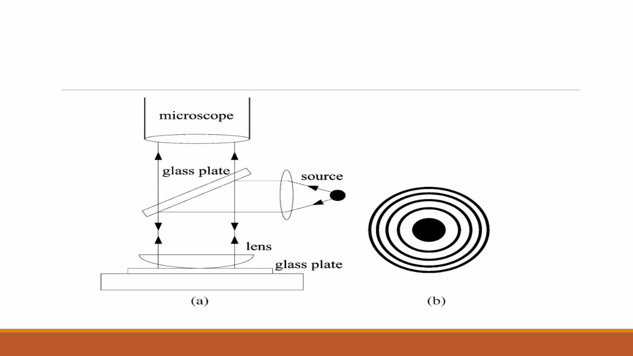
This light reflected from upper and lower surface of the air film form between plane glass plate and plno-convex lens. These rays interfere and rings are observed in the field of view. The figure shows the reflection of light form upper and lower surfaces of air film which are responsible for interference.
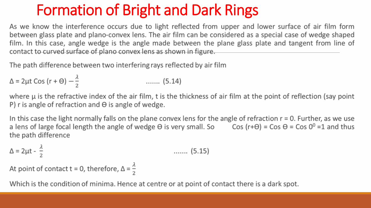
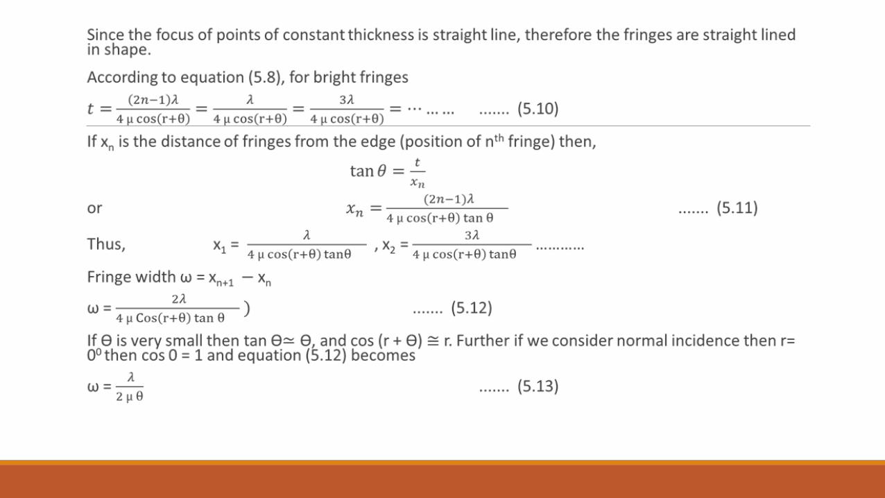
Formation of Bright and Dark Rings
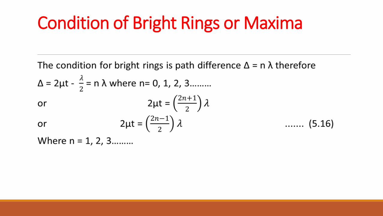
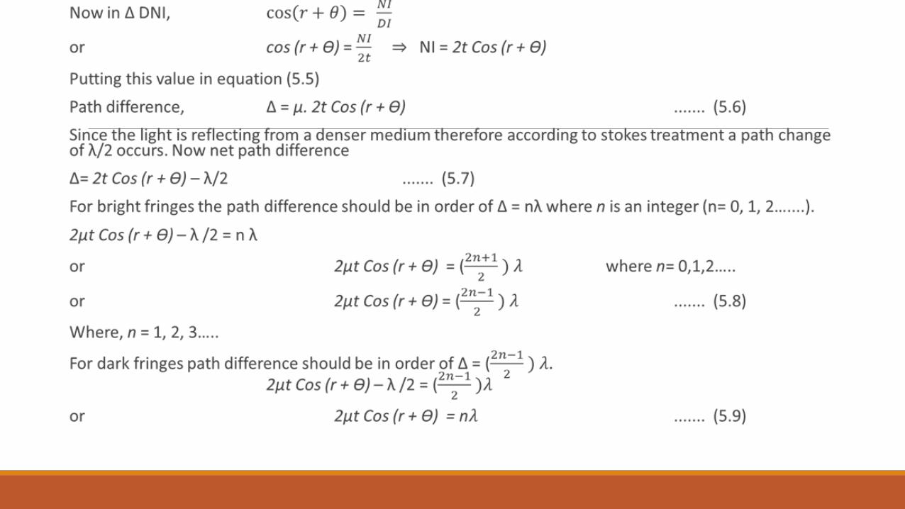
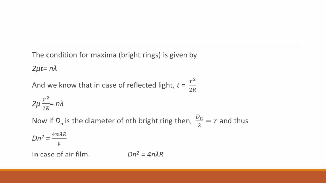
Condition of Bright Rings or Maxima
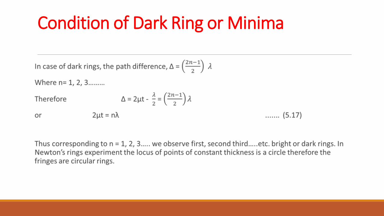
Condition of Dark Ring or Minima
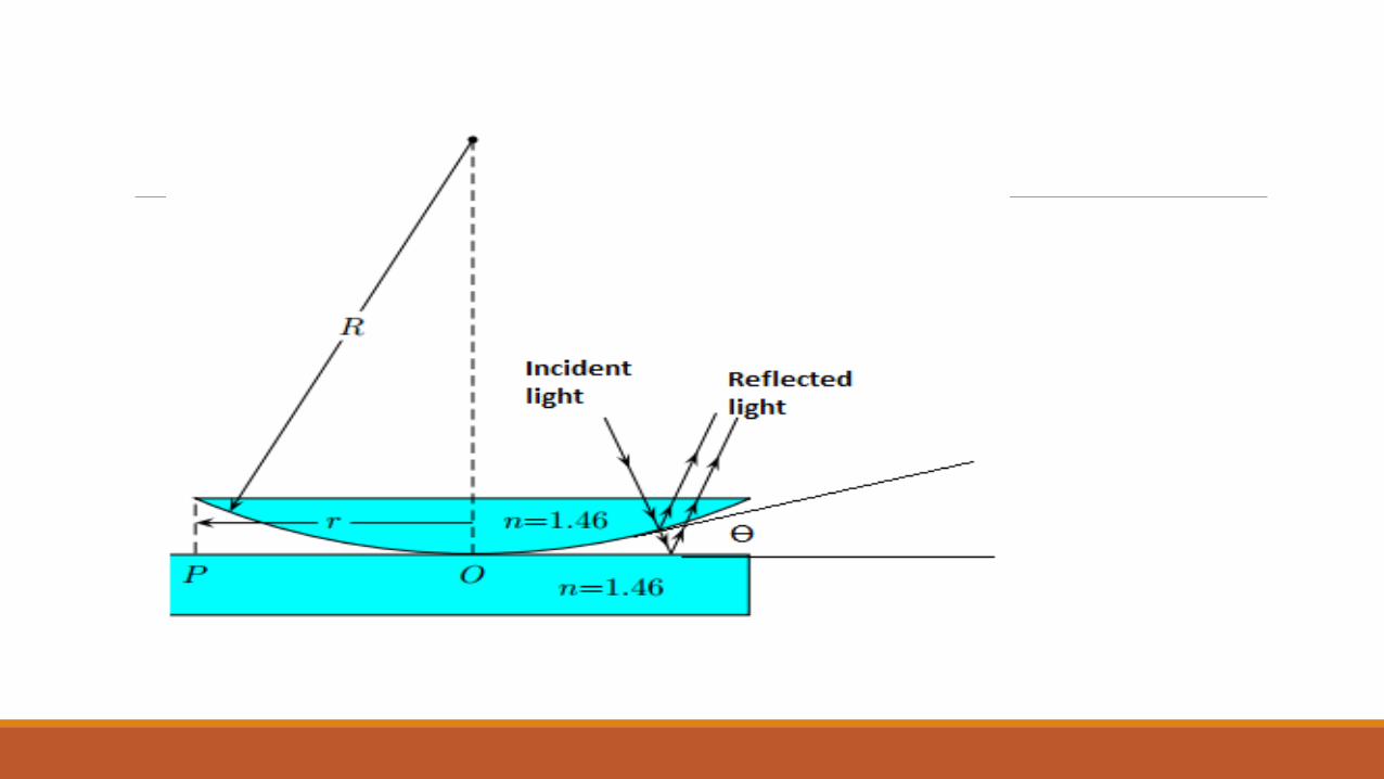
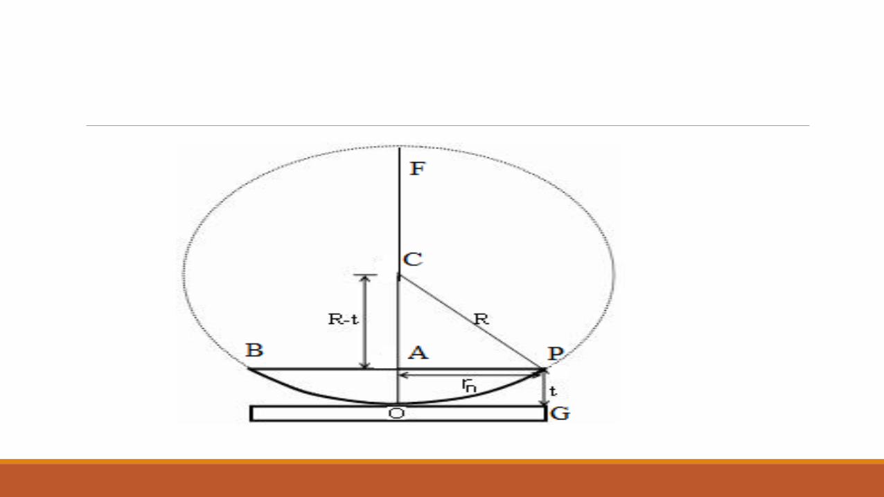
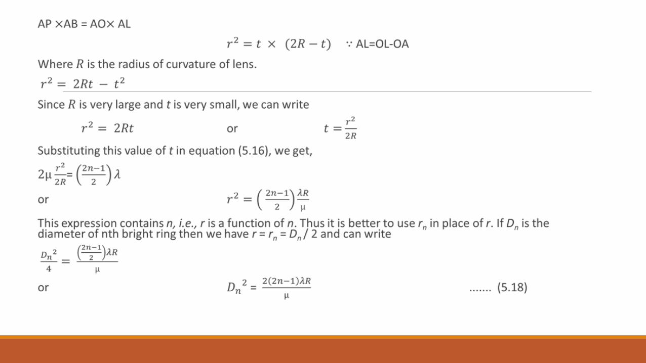
Diameter of Bright and Dark Rings In figure 5.9 the plano-convex lens BOPF is place on glass plate G and O is the point of contact. Suppose, C is the centre of the sphere OBFP from which the plano-convex lens is constructed. P is point on the air film at which the thickness of air film is t. At point P, the light is incident and reflected form the upper and lower surface of air film, and rings are formed. AP is the radius of ring passes through point P. According to property of circle
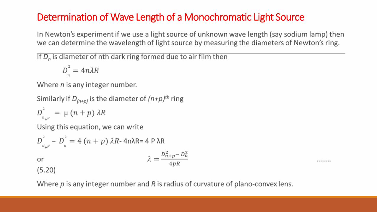
Determination of Wave Length of a Monochromatic Light Source
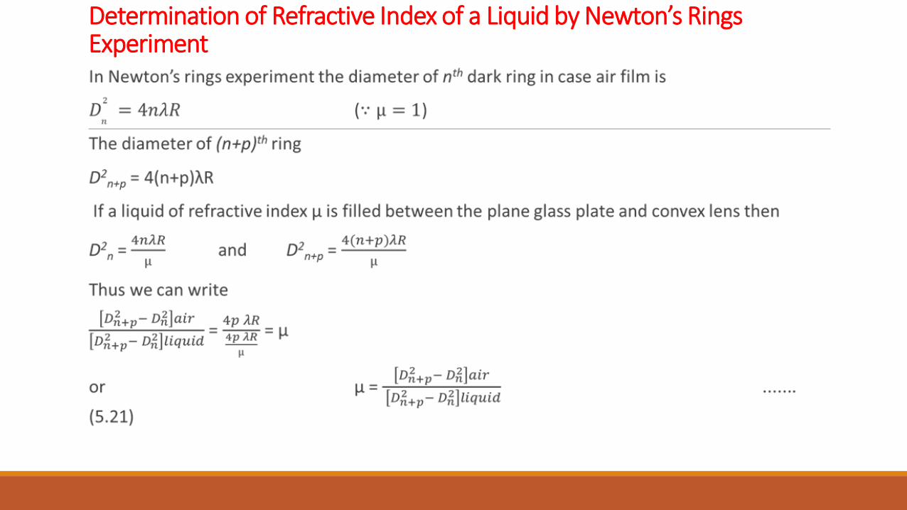
Determination of Refractive Index of a Liquid by Newton’s Rings Experiment
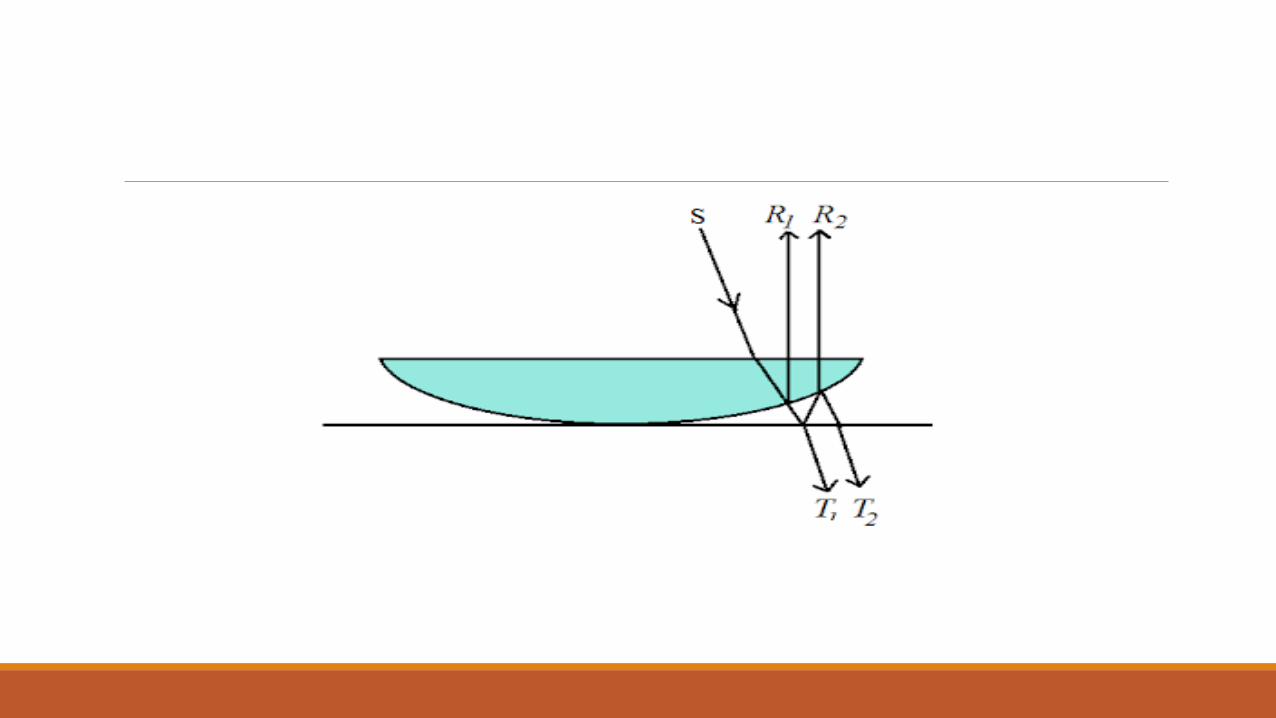
Newton’s Rings in Case of Transmitted Light
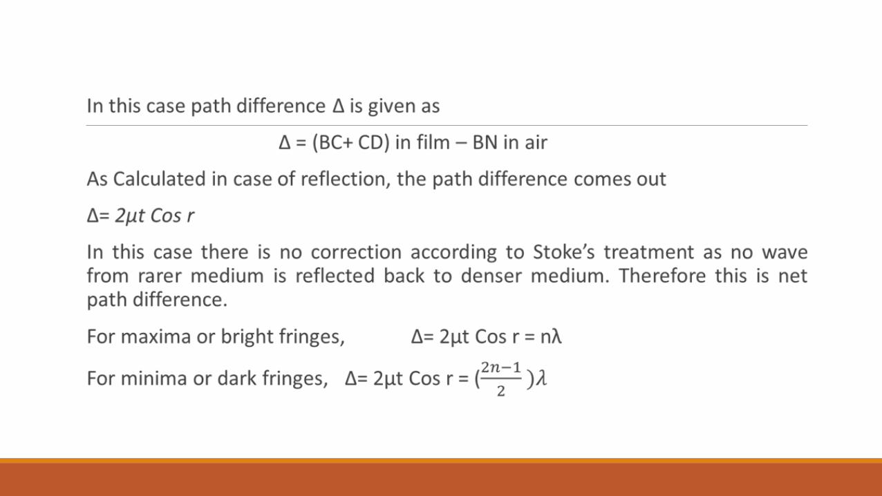
The Newton’s rings can also be formed in case of interference due to transmitted light as shown in figure. In this case the transmitted rays 1 and 2 interfere, and we can observe the rings in the field of view. In this case the net path difference between the rays is ∆= 2µt. since we will not consider the path difference arises due to reflection from denser medium. Therefore this is net path difference.
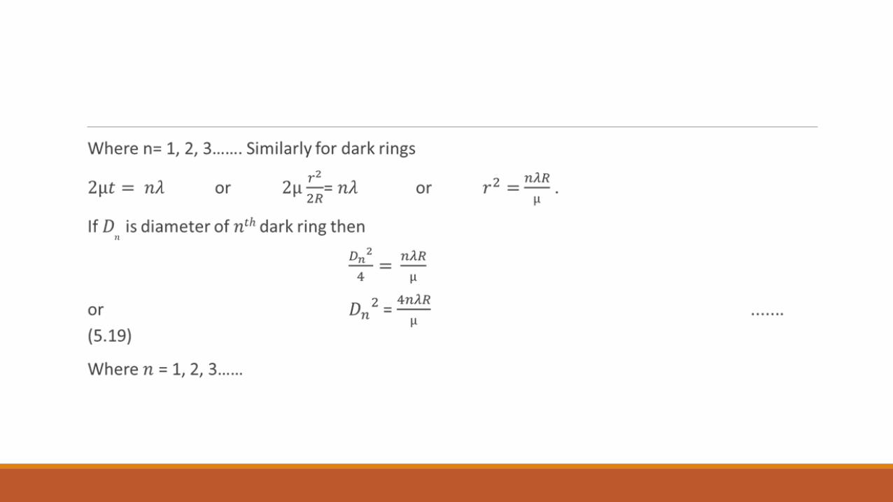
Similarly in case of minima (dark ring) the diameter nth dark ring is given by
Dn2 = 2(2n-1) λR
We can see that, this is an opposite case of reflected light. In case at point of contact the path difference is zero which is condition corresponding to bright fringe thus the centre point is bright. The rings system in this case is shown in figure.
https://youtu.be/6lULYGC6lAE
![€¦ · oõonl ' Jauao) lap p 'onna onnuado ê]apuau .!ssaas 0]01 ep auuoneJ lap auols el - !wene gssed anp a auo!znps el anodul! uou 'apnad103 uou - o.nagpu! !ssed anp :epuoJ In)](https://img.pdfslide.net/doc/110x75/60287d9933d65a064a3ba9cb/oonl-jauao-lap-p-onna-onnuado-apuau-ssaas-001-ep-auuonej-lap-auols-el.jpg)