Embed Size (px)
Citation preview

WORLD EDITOR TRAINING GUIDE
Doc number: ESD-12-P19313
Revision: 1.0, April 2013

World Editor Training Guide April 2013
i .
CONTENTS
CONTENTS ............................................................................................................................... I
INTRODUCTION .....................................................................................................................1 Learning Objectives .............................................................................................................1
PREPARE TO USE KUDA.......................................................................................................2 Run the World Editor from a Local Copy ...........................................................................2
Copy the Kuda Files and Node Assets ...........................................................................2 Start the World Editor ....................................................................................................2
BEHAVIOR BASICS ................................................................................................................4 Move an Object ....................................................................................................................4 Display a Message ...............................................................................................................4 Apply a Condition ................................................................................................................5 Using an Invisible Select Box to Enforce a Sequence .........................................................5
SECURITY DESK SCENARIO PART 1 .................................................................................6 Security Desk Logic .............................................................................................................6 Load Models into the Editor ................................................................................................7 Controlling the Camera ........................................................................................................7 Hiding a Select Object .........................................................................................................8 Select Objects' Effect on Editing .........................................................................................8 Hide the World Editor's Panels ............................................................................................9 Save the Camera View .........................................................................................................9 Create the Behavior to Open the Left-Hand Door ...............................................................9
Define the Trigger for the Behavior ...............................................................................9 Define the Action for the Behavior ..............................................................................10
Create the Behavior to Open the Right-Hand Door ...........................................................11 Close the Doors After Three Seconds ................................................................................11
Create the Timer ..........................................................................................................11 Start the Timer .............................................................................................................11 Close the Left-Hand Door When the Timer Expires ...................................................12 Edit an Existing Behavior ............................................................................................12 Close the Right-Hand Door when the Timer Expires ..................................................12
Using Pre-Defined Camera Positions ................................................................................13 Disable User Camera Control ............................................................................................13 Preview Your Work ...........................................................................................................13
UNDERSTANDING BEHAVIORS .......................................................................................14 Triggers ..............................................................................................................................14 How Triggers Work ...........................................................................................................14 Actions ...............................................................................................................................15

World Editor Training Guide April 2013
ii .
SECURITY DESK SCENARIO PART II ...............................................................................16 Create a Heads Up Display Message .................................................................................16 Control the Display of the HUD ........................................................................................17
Create the Timer and the Behavior to Start the HUD Message ...................................17 Create the Behavior which Displays the HUD ............................................................17 Create the Behavior which Hides the HUD .................................................................17 Control the Pick State for the Error Select Object (ESO) ............................................18 Create the Behavior which Moves the ESO Off-Screen ..............................................18 Create the HUD to Acknowledge that the User has Signed In on the Clipboard ........18 Create the Timer and Behaviors to Display sec_thanksHUD ......................................19 Create the Behavior which Hides sec_thanksHUD when the Timer Expires ..............19 Move the Camera to the Power Supply Unit Position .................................................19 Set the Camera Clipping Planes ...................................................................................20
THE TECH SCRIPT SPREADSHEET ...................................................................................21 Types of Information in the Tech Script ............................................................................21
Lines .............................................................................................................................21 Columns .......................................................................................................................22
Tech Script Conventions ....................................................................................................22 How the Tech Script Reflects the World Editor Hierarchy ...............................................22 Identify Sequence Loops First ...........................................................................................23
POWER SUPPLY UNIT .........................................................................................................24 Logic Flow for the Power Supply Unit Scenario ...............................................................24 Operations Covered ...........................................................................................................24 Initial Steps ........................................................................................................................24 Open the Door ....................................................................................................................25 Hide the Door .....................................................................................................................25 Hide the Select Objects ......................................................................................................25 Planning for Possible User Interactions .............................................................................25 Move the Battery Cable, Tie-Down Shroud, and Its Bolt..................................................26 Duplicating a behavior .......................................................................................................27 Stop Moving.......................................................................................................................27 Keyframed Animation .......................................................................................................28
Connecting the Battery Cable ......................................................................................28 Revealing the Lights ....................................................................................................28 Animation Ranges ........................................................................................................29
Completing the PSU Scenario ...........................................................................................29 Pin1 Logic ....................................................................................................................29 Pin2 Logic ....................................................................................................................30 Closing the Power Supply Door ..................................................................................30
FINE Tuningthe PSU Scenario ..........................................................................................31 Interactive Numeric Entry of Camera Data .................................................................31
How Camera Position Controls the Scenario .....................................................................32 Challenge Activity: Fix Flaws in the PSU Logic ...............................................................32

World Editor Training Guide April 2013
iii .
COOLANT ..............................................................................................................................33 Logic Flow for the Coolant Scenario .................................................................................33 Topics Covered ..................................................................................................................33 Initital Steps .......................................................................................................................33 Building the Scenario .........................................................................................................33 Create the Particle System .................................................................................................34 Create the Multi-Page HUD ...............................................................................................35
Create Page 1 ...............................................................................................................35 Create Pages 2 – 6 ........................................................................................................36 Finish the Coolant Scenario .........................................................................................36 Filtering in the Behaviors List .....................................................................................36 Use the nextPage Command ........................................................................................37
THE SENSORS SCENARIO ..................................................................................................38 Specifications for the Sensors Scenario .............................................................................38 Topics Covered ..................................................................................................................38 Initial Steps ........................................................................................................................38 Create the HUDs ................................................................................................................38 Create the Needle Animation .............................................................................................39 Fly the Sensor Module into Place ......................................................................................39 Create a Movable Interaction .............................................................................................39 Rotate the Multimeter Needle ............................................................................................40
SUPPLEMENTAL INFORMATION .....................................................................................41 Concept Information about the 3D Nodal Hierarchy .........................................................41 Using Kuda's Javascript Libraries ......................................................................................41

World Editor Training Guide April 2011
1
INTRODUCTION
Kuda includes an advanced JavaScript library and a World Editor that allows web developers to build interactive 3D scenarios that can be accessed through a web browser. Kuda abstracts the complexity of 3D behaviors into building blocks for common functions, which simplifies the process of creating a sequence of events that responds to user input. These interactive 3D scenarios are ideal for a variety of training purposes from presenting content to engaging learners in practice activities to testing comprehension and retention in a non-threatening, novel format.
Kuda currently provides functions for camera control, tools for transforming objects, and operations for event sequencing. Kuda's browser-based World Editor uses this library to give subject matter experts and instructional developers an environment for creating engaging 3D content without needing to write programming code. Programmers can expand Kuda by creating additional JavaScript libraries.
The Kuda Content Pipeline diagram shows how the World Editor fits into the overall Kuda architectures.
LEARNING OBJECTIVES
Although Kuda consists of several components, this class focuses on using the World Editor, itself. You will learn the procedures to accomplish the following tasks:
• Import 3D models • Use multiple camera positions • Create timers • Create motions for objects • Create and show heads-up displays (HUD) • Trigger keyframed animations • Create and use a particle system • Make objects draggable • Use camera and object positions to control event sequencing

World Editor Training Guide April 2011
2
PREPARE TO USE KUDA
RUN THE WORLD EDITOR FROM A LOCAL COPY
The Kuda World Editor, as well as the projects which it creates, can be accessed through the Chrome or Firefox web browser. Kuda runs in the WebGL environment, which is supported by versions 4.0 and later of Firefox, and by Chrome.
Copy the Kuda Files and Node Assets
1. Go to http://code.google.com/p/kuda/downloads/list and download either kuda-training-2_0_1.zip or a later version which begins with kuda-full.
Click on the name of the file in the directory list
Open this file with your program used for unzipping files.
2. Unzip the Kuda download into the C drive. This will create a directory named for the Kuda release, and will save the zip file contents into that directory.
3. Rename the directory created in step 2 to Kuda.
4. Go to http://www.nodejs.org and click on the DOWNLOAD button, and then click on the “Other release files” button.
5. Download the file called node.exe and save it into the Kuda directory you created in step 2.
6. Using Windows Explorer, navigate to your Kuda directory.
7. Create a shortcut to node.exe.
Right-click on node.exe.
Select Create Shortcut. An icon will appear called “Shortcut to node.exe.”
Drag the icon out of the Explorer window and onto your desktop.
8. Right click on the shortcut and select Properties. Assuming that your Kuda directory is C:\Kuda,
set the Target parameter to “C:\Kuda\node.exe app”
Set the Start In parameter to “C:\Kuda.”
Click OK.
Start the World Editor
1. Double-click on the node shortcut which you put on your desktop. (This displays a message that Kuda is running at localhost:3000.)
2. Click Run in the security warning, if one appears.
3. Open Chrome or Firefox and, in the address bar, enter localhost:3000. The World Editor loads.
If you use Firefox and find that the World Editor will not load:
For PK Zip 1. Click on Extract Files. 2. Find the directory. 3. Use default settings 4. Press Extract button. 5. Press Close.

World Editor Training Guide April 2011
3
4. Enter “about:config” in the Firefox address bar (with no quotes) and then press the Enter key. You will see a list of parameters which control the behavior of Firefox.
5. In the Filter: line, type “webgl” and press Enter.
6. Find the line that says webgl.force-enabled.
7. Double-click on that line so that the right-hand columns read "user set boolean true."
This will allow Firefox to run the Kuda World Editor.
The following figure shows the opening screen of the World Editor.
World Editor Training Guide April 2011
4
BEHAVIOR BASICS
In the Kuda World Editor, all events are controlled by Behaviors. Behaviors are cause-and-effect operations (or if-then statements if you are familiar with programming). For example: if the user clicks this button, then that door opens; when this timer runs out, a heads-up display shows a warning message. The material in this section explains how to design instructional scenarios from logical sequences of behaviors.
MOVE AN OBJECT
1. Load the file basic_01.html into your bowser. File menu, Open File, kuda/basics/basic_01/basic_01.html
2. Click on the empty background area.
3. Click on the red cube.
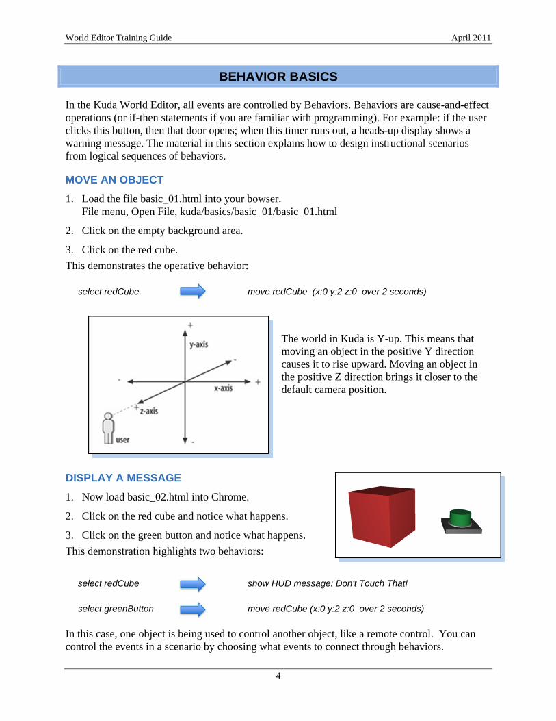
This demonstrates the operative behavior:
select redCube move redCube (x:0 y:2 z:0 over 2 seconds)
The world in Kuda is Y-up. This means that moving an object in the positive Y direction causes it to rise upward. Moving an object in the positive Z direction brings it closer to the default camera position.
DISPLAY A MESSAGE
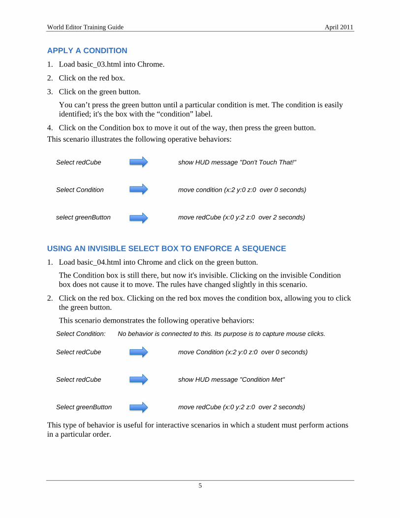
1. Now load basic_02.html into Chrome.
2. Click on the red cube and notice what happens.
3. Click on the green button and notice what happens.
This demonstration highlights two behaviors:
select redCube show HUD message: Don't Touch That! select greenButton move redCube (x:0 y:2 z:0 over 2 seconds)
In this case, one object is being used to control another object, like a remote control. You can control the events in a scenario by choosing what events to connect through behaviors.
World Editor Training Guide April 2011
5
APPLY A CONDITION
1. Load basic_03.html into Chrome.
2. Click on the red box.
3. Click on the green button.
You can’t press the green button until a particular condition is met. The condition is easily identified; it's the box with the “condition” label.
4. Click on the Condition box to move it out of the way, then press the green button.
This scenario illustrates the following operative behaviors:
Select redCube show HUD message "Don't Touch That!"
Select Condition move condition (x:2 y:0 z:0 over 0 seconds)
select greenButton move redCube (x:0 y:2 z:0 over 2 seconds)
USING AN INVISIBLE SELECT BOX TO ENFORCE A SEQUENCE
1. Load basic_04.html into Chrome and click on the green button.
The Condition box is still there, but now it's invisible. Clicking on the invisible Condition box does not cause it to move. The rules have changed slightly in this scenario.
2. Click on the red box. Clicking on the red box moves the condition box, allowing you to click the green button.
This scenario demonstrates the following operative behaviors:
Select Condition: No behavior is connected to this. Its purpose is to capture mouse clicks.
Select redCube move Condition (x:2 y:0 z:0 over 0 seconds)
Select redCube show HUD message "Condition Met"
Select greenButton move redCube (x:0 y:2 z:0 over 2 seconds)
This type of behavior is useful for interactive scenarios in which a student must perform actions in a particular order.

World Editor Training Guide April 2011
6
SECURITY DESK SCENARIO PART 1
This training guide uses a sample scenario for preparing an imaginary group of experiments to load onto an orbital vehicle for spaceflight. The training scenario is broken into four sections:
• The security desk, parts 1 and 2
• The power supply unit (PSU)
• The coolant system
• The sensors
The following activities provide an introduction to using the World Editor's features as you build the first part of the World Editor Training scenario. These activities also set a context for the technical material which follows.
SECURITY DESK LOGIC
When you begin creating a scenario, you usually work from a storyboard that a client provides or that you create. For each section, such as part 1 of the Security Desk Scenario, you will analyze the storyboard and describe how you will meet the objectives.
For example, the Security Desk Scenario requires a sign-in procedure before the student can pass through the entry doors.
The following bulleted items describe the logic flow for building the Security Desk Scenario.
• Two invisible select objects (SO) cover the entire doorway.
– Closer to the camera, and covering the doors, is an invisible error select object (ESO) which captures the mouse click and starts the alternate event path if a user forgets to sign in.
– Behind the invisible error select object is the select object which opens the doors and moves the camera.
• The user clicks on the clipboard to sign in (move the error select object out of the way).
• Clicking on the select object for the doors:
– Opens the doors
– Starts a timer
– When the timer stops, the camera moves to the next position
– In the background, after another timer stops, the doors close

World Editor Training Guide April 2011
7
LOAD MODELS INTO THE EDITOR
The first operation is to load the pre-existing models into the editor.
1. Go back to localhost:3000 in the address bar of your browser.
2. Click on the Geometry tool group in the left-hand pane of the World Editor. The Geometry Browser tool loads by default.
3. At the top of the window, select the Load a Model menu.
This shows a list of the models contained in your public/assets directory. (You placed them there when you downloaded the class materials.)
4. Select the scenery model, and see the model loaded into the 3D view.
5. Repeat this procedure for the following models:
• Security_SO_doors • Security_SO_error • Sec_clipboard • Payload • Table You will not see all the objects in the World Editor when they are loaded.
CONTROLLING THE CAMERA
Learning to use the camera is an important step in operating the World Editor. You first set a camera position which allows you to clearly see and interact with objects.
1. Drag upward on the mouse so that you are looking straight into the scene (front view).
2. Drag downward on the mouse while holding any mouse button so you’re looking straight down on the scene. The position does not have to be precise.
This causes the Camera to orbit around a point in space called the Camera Target. The Camera Target is not something which is drawn in the 3D view.
3. Shift-drag with any mouse button so that the area near the white item on the desk is centered in the view. This causes both the Camera and Camera Target to move along the plane that is perpendicular to the direction in which the camera is facing.
4. Truck the camera in closer by scrolling upward with the mouse wheel.
5. Alternate between trucking the camera in and centering your view using the top and front views. Position the 3D camera so that you can see the gray box, the red sign, and the clipboard.
World Editor Training Guide April 2011
8
HIDING A SELECT OBJECT
Two objects in your camera view are blocking your view of the security doors, and those objects need to be hidden. These are the select objects used for the security doors. Select objects are useful when a selectable feature is made of many sub-objects, or is difficult to click on.
1. If necessary, click the Geometry tool group in the panel so you can see the tool icons.
2. If necessary, select the Geometry Browser tool. When a tool is selected, it is highlighted in bright blue.
3. In the 3D view, click on the gray box blocking your view of the doors. The box will turn bright blue when selected.
4. In the panel on the right-hand side of the World Editor, select the Browser Tree tab (the tab turns blue when it is active).
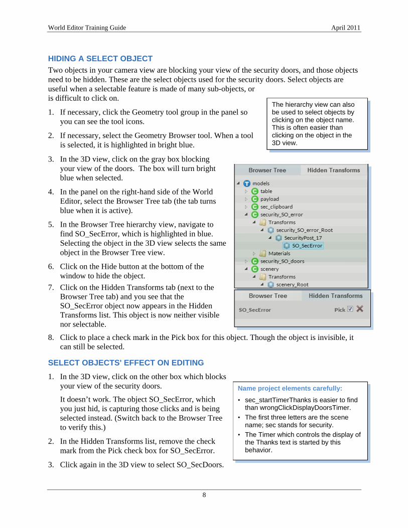
5. In the Browser Tree hierarchy view, navigate to find SO_SecError, which is highlighted in blue. Selecting the object in the 3D view selects the same object in the Browser Tree view.
6. Click on the Hide button at the bottom of the window to hide the object.
7. Click on the Hidden Transforms tab (next to the Browser Tree tab) and you see that the SO_SecError object now appears in the Hidden Transforms list. This object is now neither visible nor selectable.
8. Click to place a check mark in the Pick box for this object. Though the object is invisible, it can still be selected.
SELECT OBJECTS' EFFECT ON EDITING
1. In the 3D view, click on the other box which blocks your view of the security doors.
It doesn’t work. The object SO_SecError, which you just hid, is capturing those clicks and is being selected instead. (Switch back to the Browser Tree to verify this.)
2. In the Hidden Transforms list, remove the check mark from the Pick check box for SO_SecError.
3. Click again in the 3D view to select SO_SecDoors.
The hierarchy view can also be used to select objects by clicking on the object name. This is often easier than clicking on the object in the 3D view.
Name project elements carefully:
• sec_startTimerThanks is easier to find than wrongClickDisplayDoorsTimer.
• The first three letters are the scene name; sec stands for security.
• The Timer which controls the display of the Thanks text is started by this behavior.

World Editor Training Guide April 2011
9
4. Click on the Hide button to hide SO_SecDoors.
Now the security doors are visible.
5. Turn on Pick for SO_SecDoors and SO_SecError so that they will function as invisible select objects.
HIDE THE WORLD EDITOR'S PANELS
The World Editor's panels can cover a portion of your camera view. To see what is within the camera's field of view, you need to temporarily hide these panels.
1. Move the mouse so that the cursor is hovering over the right-hand panel. An arrow appears at the edge which separates that panel from the 3D view.
2. Click on that arrow, and the panel will recede into the window border.
3. Use the same technique to hide the left-hand panel, and you'll be able to better see what is framed in your camera position.
4. Adjust the camera view so that you can clearly see the clipboard on the desk, as well as the payload in the room beyond the security doors and the sign on the wall above the clipboard.
5. To unhide the panels, click the arrows at the borders of the World Editor window.
SAVE THE CAMERA VIEW
1. In the left-hand panel, click on the Camera tool group and then click the Viewpoints tool to bring up the Viewpoint panels on the right.
You can type information into the Camera Information input fields if you already know the appropriate numbers, or you can automatically fill them in with numbers from the current camera position.
2. In the Create a Viewpoint panel, click on the Use Current Camera button.
3. Type the name sec_camPos into the Save Viewpoint field, and click the Save button.
If you have difficulty finding a good camera position, the following values work well.
Camera Position 0.5 1.6 3
Camera Target 0.2 1.3 0
CREATE THE BEHAVIOR TO OPEN THE LEFT-HAND DOOR
Define the Trigger for the Behavior
1. In the left panel, select the Behaviors tool group. If it is not already selected, click on the Behaviors tool.
The Behaviors Editor is divided into two windows. The top window is used to create behaviors, and the bottom window lists behaviors which have been saved.

World Editor Training Guide April 2011
10
The Create Behavior window is divided into three columns.
2. In the Triggers column, select the Model category from the drill-down menu.
3. Select the Citizen named security_SO_doors.
A 3D object file loaded into the World Editor is a Citizen. A Citizen can have many named sub-objects. In this window, the M does not stand for Model but denotes things which can send a Message. The C stands for Citizen. T stands for Trigger. In the pickable shapes category, all the sub-objects can send a message that triggers various actions to occur.
4. Select the pickable shapes category.
5. Select the object named SO_SecDoors.
The Model category lists all the 3D models which have been loaded into the Kuda World Editor. Those models are listed as Citizens. Each model can contain one or more pickable shapes, depending on the internal structure of that model. Because you may need to repeatedly access the various pickable shapes, note which shapes are components of which 3D models.
Define the Action for the Behavior
1. Click in the Action drill-down menu and select the Model category.
2. Select the scenery citizen.
3. Select the transforms category. You are creating a behavior which will cause this model to move.
4. Select the scenery_root citizen. This 3D model has a group called scenery_root which holds all its sub-models.
5. Open the scenery_G group.
6. Select the SecDoor_L citizen.
7. Select the functions category.
8. Select move from within the functions category.
Some data input fields appear so you can specify how to move the object.

World Editor Training Guide April 2011
11
Enter -0.5 for X, 0 for Y, and 0 for Z in the delta parameters.
Enter 1 for time, which causes the move to take 1 second to complete.
In the Save Behavior text field, enter sec_openDoorLeft as the behavior name, and press the Save button.
You have just created a behavior so that clicking on SO_SecDoors causes SecDoor_L to slide open. In the Behaviors panel, you’ll see your newly created behavior.
CREATE THE BEHAVIOR TO OPEN THE RIGHT-HAND DOOR
1. For the trigger, select Model / security_SO_doors / pickable shapes / SO_SecDoors
2. For the Action, select Model / scenery / transforms / scenery_root / scenery_G / SecDoor_R / functions / move
3. Enter 0.5 for X, 0 for Y, 0 for Z, and 1 second for the time.
4. Save this behavior as sec_openDoorRight.
CLOSE THE DOORS AFTER THREE SECONDS
The behaviors which close the doors are nearly identical to the behaviors which open the doors. Since the doors will remain open a fixed amount of time after being opened, you'll use a timer to close the doors. The trigger which causes the doors to open will work for starting this timer. Begin by creating the timer which is the trigger for closing the doors.
Create the Timer
1. Select the Timers tool on the left-hand panel, in the Behaviors tool group.
2. Enter 3 for the start time (durations of Timers are entered in seconds).
3. In the Name field, Enter sec_timerHoldDoorsOpen and Save the timer.
Start the Timer
1. In the behaviors tool, select for the Trigger: Model / security_SO_doors / pickable shapes / SO_SecDoors
2. For the Action, choose Timer / sec_timerHoldDoorsOpen / functions / start
3. Save this behavior as sec_startTimerHoldDoorsOpen. When the doors begin opening, a three-second timer starts. You'll use the end of this timer as a Trigger to close the doors.

World Editor Training Guide April 2011
12
Under the Hood In 3D animation, every 3D model is controlled by a transform. The transform holds the position, rotation, and scale values for a 3D model. When you move, rotate (turn), or scale a 3D model, you are sending new data to that model's transform. The transform also contains data regarding an object's pickable state as well as its visibility, so remember to look in the transforms category when you set values for those.
Close the Left-Hand Door When the Timer Expires
1. From the Behaviors tool, set up a trigger from Timer / sec_timerHoldDoorsOpen / messages / stop
2. For the Action, choose: Model / scenery / transforms / scenery_root / scenery_G / SecDoor_L / functions / move
3. Enter 0.5, 0, 0 for the delta, and 1 second for the time.
4. Save this behavior as sec_closeDoorLeft.
Edit an Existing Behavior
1. In the list of behaviors at the bottom of the screen, find the behavior called sec_openDoorRight.
2. To the right of that behavior name click the Edit behavior button, which looks like a pencil.
Your previously saved behavior is loaded into the editor.
3. Change the time parameter from 1 to 0.5, and then save this behavior as openRightDoorFast.
Notice sec_openDoorRight is no longer listed. When you edited the behavior, you changed its name rather than creating a similar behavior under a new name. Saving a behavior under a different name does not create a new behavior; it renames the existing behavior. (Later, you will use the Duplicate This Behavior button to create an additional similar behavior.)
4. If the editor (the top window) currently has a behavior loaded, click the Clear button. This does not erase values from a behavior or delete a behavior. It just clears the data from the editor window.
5. Click the Edit button for openRightDoorFast.
6. Change the time back to 1, the name back to sec_openDoorRight, and then save it.
Close the Right-Hand Door when the Timer Expires
1. For the Trigger, choose Timer / sec_timerHoldDoorsOpen / messages / stop
2. For the Action, choose Model / scenery / transforms / scenery_root / scenery_G / SecDoor_R / functions / move
3. Enter -0.5, 0, 0 for the delta, and 1 second for the time.
4. Save this behavior as sec_closeDoorRight.

World Editor Training Guide April 2011
13
What’s Next
The next section provides more detailed information about Behaviors in the World Editor.
USING PRE-DEFINED CAMERA POSITIONS
Before you can preview what you’ve created, you need to tell the camera to go to your saved position so you can interact with your scene.
1. Go to the Behaviors editor and, for the Trigger, select [Any source] / ready. This trigger sends a signal when all objects are loaded and the world is ready for interaction.
2. For the Action, select Camera / Main Camera / functions / moveToView.
3. In the parameter fields that appear,
Click in View field.
Select Viewpoint / sec_camPos.
Enter 0 (zero) for the time value, because this camera move will be instant.
Save this behavior as cam_gotoSec.
DISABLE USER CAMERA CONTROL
Because you will control the camera's movement with defined viewpoints, you need to disable user control of the camera.
1. For the trigger, select [Any source] / ready
2. For the action, select Camera / Main Camera / functions / disableControl
3. Save this behavior as cam_keepViews.
PREVIEW YOUR WORK
1. Turn on Pick for SO_SecDoors but not for SO_SecError. (You'll do that later.)
2. Save your project! This is important to do before you Preview a project.
In the left-hand panel, near the top, click in the Unsaved Project text entry field.
Type a name for your project.
Click on the Save button.
3. After saving, click again in the same text field (which now shows your project name), and then click the Preview button. After the camera moves into position, try clicking on the doors. The doors should open, pause, and then close.
4. After you have previewed your project, click the Stop Preview button.

World Editor Training Guide April 2011
14
UNDERSTANDING BEHAVIORS
In the World Editor, a Behavior is the link from a Trigger to an Action. When you load an object or model into the World Editor, Kuda automatically creates Triggers associated with the object.
You select a Trigger which causes an Action to be performed when the Trigger event occurs.
Trigger + Action = Behavior
TRIGGERS
The following list items are examples of various triggers.
• If the world is ready
• If an object is loaded (or unloaded)
• If an object is clicked on (selected)
• If an animation starts (or stops)
• If a turn or move starts (or stops)
• If the camera starts moving, stops moving, or arrives at a particular viewpoint
• A particle system can act as a trigger. It sends a message when it starts and stops. This message can start another action.
– A Trail particle effect is started (or stopped)
– Burst particle effect is shown
– An emitter particle effect is shown
• If a Scene is loaded (or unloaded)
• If an HUD is shown
• If a timer starts or stops
HOW TRIGGERS WORK
One Trigger can cause multiple Actions to take place. A Trigger is permanently linked to an Action and can’t be redefined during the execution of a scenario.
For example, consider the issues in defining a behavior that allows a user to click on a door to open it, and then click on the same door to close it.
a) Clicking on a door (the Trigger) causes the door to rotate to an open position – the Action. (The World Editor uses the term Turn for rotation.)
b) After the door is open, you will want to close it. You have already defined a behavior to open the door in the open direction when a user clicks on the door. You can't change that behavior in the middle of your scenario.

World Editor Training Guide April 2011
15
One approach could employ swapping out visible objects. With this method, each model only has one trigger.
a) If the door is closed, clicking on it causes it to open.
b) Once the door is open, it instantly moves off-screen and another model of an open door instantly moves to its place.
c) Clicking on the open door causes it to close, and then swaps out the open door for the closed door model.
A problem with this method is screen refresh rates and timing. The World Editor does not support volumes of time such as keyframes. So as the door races off-screen, a screen refresh could simultaneously occur and cause the door to be redrawn somewhere along the path.
For this reason, a better approach is to use invisible Select Objects.
a) The door is closed, but it can’t be clicked on because an invisible Select Object (SO) is in the way.
b) Clicking on the invisible SO causes the door to open and disables "pick" for that SO.
c) Clicking on the open door closes the door and re-enables pick for the SO.
No behaviors need to be redefined mid-stream for this to work.
ACTIONS
You define Actions to control the resulting effects when a Trigger is initiated. The following list shows examples of typical Actions.
• Start (or stop) an animation
• Enable or disable user-control of the camera
• Move the camera to a specified view or along a curve
• Manually place the camera's target point or move the camera
• Move or rotate an object
• Display, hide, or change the page in a heads up display HUD
• Display, hide, or change the selectability (Pick) of objects
• Start, stop, or burst a Particles event
• Set a scene change
• Start, stop, reset, or resume a timer
What’s Next
The next section guides you through part two of the Security Desk section of the scenario. In this section, you will learn how to use invisible select objects and to create heads up display (HUD) messages to give instructions to a user.

World Editor Training Guide April 2011
16
SECURITY DESK SCENARIO PART II
When you previewed and saved the project, you created behaviors to open the security doors and then close them again after a short delay. In this section, you will create the following behaviors.
• Create and display text messages to instruct the user
• Move the camera to the next position after the doors open
• Require the user to click on the clipboard (as a form of signing in) before approaching the power supply unit
CREATE A HEADS UP DISPLAY MESSAGE
A user won’t be allowed through the security doors until he or she clicks on the clipboard, so you will create a heads up display (HUD) message to remind the user.
1. On the left-hand panel, click on the HUD tool group and then click on the HUD tool.
The HUD Outline panel appears on the right.
2. Click in the text entry field and type the name sec_ErrorHUD, then click on the Create New Display button.
The title of the HUD appears at the top of the panel along with buttons to add or remove pages.
3. Click the Add Page button.
4. Click the Add Text button to create the message which will display if the user tries to enter the doors without signing in.
The Set Text Properties panel appears.
5. In the Text field, enter the following:
You must first sign in! (Use the clipboard.)
6. Complete the remaining fields as follows:
Parameter Values Notes
Width 160
Position x: 300, y: 200 The Position field specifies the number of pixels from the upper-left corner of the screen to the center of the HUD.
Color 1, 1, 0.6, 1 The default color is yellow.
Size 14
Font Helvetica
Style Bold
Alignment Center
7. Click the Save button.
The newly created HUD appears in the HUD Outline. Clicking on a Page of any HUD in the outline will display that HUD page in the 3D view.

World Editor Training Guide April 2011
17
CONTROL THE DISPLAY OF THE HUD
Create the Timer and the Behavior to Start the HUD Message
1. Using the method you already learned, create a 2 second timer and save it as sec_errorTimer.
The Timers tool is in the Behaviors tool group. The procedure is covered on page 11, if you need to review.
2. Select the Behaviors tool.
3. In the Triggers column, select: Model / security_SO_error / pickable shapes / SO_SecError
security_SO_error is the file name where the 3D object, SO_SecError, is saved.
4. For the Action, choose Timer / sec_errorTimer / functions / start
5. In the Name field, type in sec_startErrorTimer and click the Save button.
Create the Behavior which Displays the HUD
1. In the Triggers column, select: Model / security_SO_error / pickable shapes / SO_SecError
2. In the Actions panel, select the HudDisplay category, the Sec_ErrorHUD citizen, the functions group, and the "show" action
3. In the Behaviors panel, save this behavior as sec_errorShowHUD.
Create the Behavior which Hides the HUD
1. In the Triggers panel, select the Timer category, the sec_errorTimer citizen, the messages group, and the stop event.
2. Similar to displaying the HUD, select the "hide" Action for sec_errorHUD.
3. Save this behavior as sec_errorHide.
Note that the same Trigger (selecting SO_SecError) caused multiple Actions to take place: starting the timer and displaying the HUD. You now have a heads-up display which appears for 2 seconds when a user clicks on the error select object.

World Editor Training Guide April 2011
18
Control the Pick State for the Error Select Object (ESO)
Before you previewed the project (on page 13), you turned off Pick for the ESO. If you could pick the ESO, it would block your ability to pick the select object, and the doors would not work.
In this procedure, you need to be able to select the ESO to work with it, and you will learn about the benefits of using the Geometry Browser.
1. In the left-hand panel, click on the Geometry tool group and then click the Geometry Browser tool.
The Geometry Browser allows you to pick objects for editing, even if they have pick disabled for the 3D viewport. Using the Geometry Browser, you can also find where 3D models exist in the object hierarchies. This can make finding those objects easier when you create Behaviors.
2. Select the Hidden Transforms tab and turn on Pick for SO_SecError.
Create the Behavior which Moves the ESO Off-Screen
1. Go to the Behaviors editor.
2. For the Trigger, choose Model / sec_clipboard / pickable shapes / pCylinderShape27
3. For the Action, choose Model / security_SO_error / transforms / security_SO_error_root / security_SO_error / functions / move
4. Enter 0 for X (horizontal) movement, 30 for Y (upward) movement, and 0 for Z (forward) movement.
When the user clicks on the clipboard, this behavior moves the ESO up, far outside the camera view. In this position, the user can no longer click on the ESO.
5. Save this behavior as sec_hideESO.
Create the HUD to Acknowledge that the User has Signed In on the Clipboard
1. Open the HUD panel and create a new HUD named sec_thanksHUD.
2. Add a page, and then add a Text element to that HUD.
3. Set the parameters as follows:
Parameter Values Notes
Text Thank you!
Width 120
Position x: 500, y: 300 The Position field specifies the number of pixels from the upper-left corner of the screen to the center of the HUD.
Color 1, 1, 0.6, 1 The default color is yellow.
Size 18

World Editor Training Guide April 2011
19
This structure is common in this project:
1. Selecting an object displays a HUD and starts a Timer.
2. When the Timer expires, it hides the HUD.
Font Helvetica
Style Bold
Alignment Center
4. Click the Save button to save this HUD.
Create the Timer and Behaviors to Display sec_thanksHUD
1. Create a 2 second timer called sec_timerThanks.
2. In the Behavior Editor, select for a trigger: Model / sec_clipboard / pickable shapes / pCylinderShape27
3. In the Actions panel, select Timer / sec_timerThanks / functions / start.
4. Save this behavior as sec_startTimerThanks.
5. Now create another behavior which uses selection of pCylinderShape27 as the Trigger and which causes sec_thanksHUD to be displayed.
6. Save this behavior as sec_showThanksHUD.
Create the Behavior which Hides sec_thanksHUD when the Timer Expires
1. Select Timer / sec_timerThanks / messages / stop for the trigger.
2. For the Action, hide sec_thanksHUD.
3. Save this behavior as sec_hideThanksHUD.
Move the Camera to the Power Supply Unit Position
1. Create a 1 second timer, and save it as sec_Timer_entryDelay.
2. Create a behavior so when the user picks SO_SecDoors, sec_Timer_entryDelay starts.
3. Save the Behavior as sec_startTimer_entryDelay.
4. Position the camera so you have a clear view of the power supply unit doorway. Use the mouse controls as you did on page 7.
5. When you are satisfied with your camera position, press the Use Current Camera button in the Create a Viewpoint panel.
6. Before you save the Viewpoint, follow the procedures in the next section.
This clipboard object, pCylinderShape27, was not named well before it was exported from Maya. You'll encounter such badly named objects at times.
World Editor Training Guide April 2011
20
Set the Camera Clipping Planes
To draw 3D objects efficiently, 3D programs use clipping planes. When a 3D program displays a scene, the scene must be organized based on how distant objects are from the camera. Overlapping objects which are almost equidistant from the camera can generate a drawing error called z-fighting. The near and far clipping planes limit the depth of the region of interest from the front of the scene to the back of the scene relative to the position of the camera. Enclosing the region of interest more tightly with clipping planes increases the precision with which the software can organize the objects, reducing or eliminating z-fighting. This benefit comes with a cost: objects which are closer to the camera than the near clipping plane, or which are further from the camera than the far clipping plane will not be drawn in the 3D view.
Because the camera will be looking at objects from a close vantage point, you need to adjust the clipping planes. The Near and Far fields for the clipping planes are in the Create a Viewpoint panel, just above the Use Current Camera button.
1. Set the Near Plane to 0.02 and the Far Plane to 30.
2. Save this camera position as psu_camPos.
3. Set the end of sec_Timer_entryDelay to cause the camera to move to psu_camPos over 3 seconds. (Remember that the Action is Camera / Main Camera / moveToView)
4. Save this behavior as sec_camGotoPSU.
What’s Next
The next section describes using a Tech Script spreadsheet to keep track of the behaviors in a scenario. This is a good time for a short break.

World Editor Training Guide April 2011
21
THE TECH SCRIPT SPREADSHEET
So far, the names of Citizens and Behaviors have been as descriptive as possible, denoting the chapter (or scenario), the type of Citizen, and the type of Action performed by a Behavior. While this is helpful for finding a particular Behavior, such as a start, hide, or show in the Behaviors tool, it quickly becomes necessary to have a detailed list of all behaviors in a project. The Technical Script is a spreadsheet approach to recording and managing all the constructs you create and manipulate in a scenario.
In a spreadsheet program, load the file TechScript.xlsx.
This spreadsheet begins with a list of all the Actions which take place once all objects have been loaded and the scene is ready for interaction.
Examine the Security Desk scenario, listed in lines 13 through 28.
TYPES OF INFORMATION IN THE TECH SCRIPT
The information in the columns and rows of the Tech Script reflects all the objects, triggers, actions, and interactions for the entire scenario. The information is organized into lines and columns.
Lines
The lines of information are organized into sections for each part of the scenario. In each section, the lines list all the behaviors with their exploded contents. The lines are also ordered to make it easy to see the sequence of actions and interactions among the objects in each section.
Lines 13 through 126 list all the behaviors in this project, followed by details on the particle system, details for some HUD displays, a list of all timers and their durations, and finally a list of all camera positions.
World Editor Training Guide April 2011
22
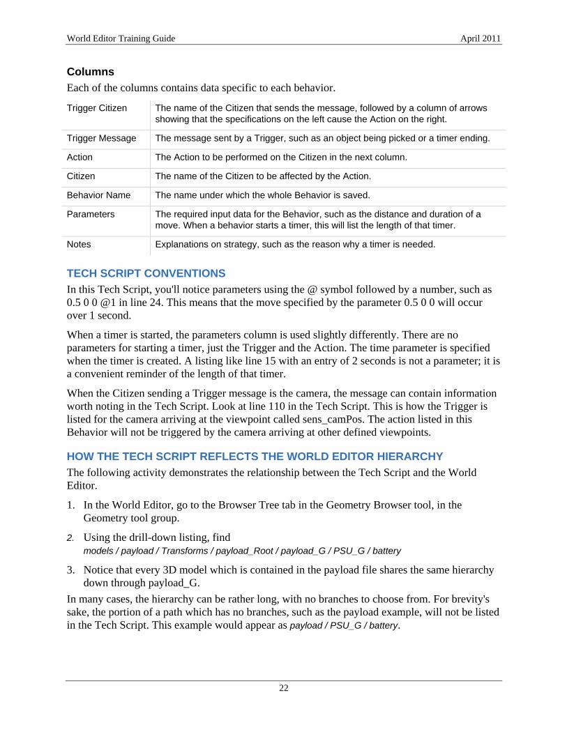
Columns
Each of the columns contains data specific to each behavior.
Trigger Citizen The name of the Citizen that sends the message, followed by a column of arrows showing that the specifications on the left cause the Action on the right.
Trigger Message The message sent by a Trigger, such as an object being picked or a timer ending.
Action The Action to be performed on the Citizen in the next column.
Citizen The name of the Citizen to be affected by the Action.
Behavior Name The name under which the whole Behavior is saved.
Parameters The required input data for the Behavior, such as the distance and duration of a move. When a behavior starts a timer, this will list the length of that timer.
Notes Explanations on strategy, such as the reason why a timer is needed.
TECH SCRIPT CONVENTIONS
In this Tech Script, you'll notice parameters using the @ symbol followed by a number, such as 0.5 0 0 @1 in line 24. This means that the move specified by the parameter 0.5 0 0 will occur over 1 second.
When a timer is started, the parameters column is used slightly differently. There are no parameters for starting a timer, just the Trigger and the Action. The time parameter is specified when the timer is created. A listing like line 15 with an entry of 2 seconds is not a parameter; it is a convenient reminder of the length of that timer.
When the Citizen sending a Trigger message is the camera, the message can contain information worth noting in the Tech Script. Look at line 110 in the Tech Script. This is how the Trigger is listed for the camera arriving at the viewpoint called sens_camPos. The action listed in this Behavior will not be triggered by the camera arriving at other defined viewpoints.
HOW THE TECH SCRIPT REFLECTS THE WORLD EDITOR HIERARCHY
The following activity demonstrates the relationship between the Tech Script and the World Editor.
1. In the World Editor, go to the Browser Tree tab in the Geometry Browser tool, in the Geometry tool group.
2. Using the drill-down listing, find models / payload / Transforms / payload_Root / payload_G / PSU_G / battery
3. Notice that every 3D model which is contained in the payload file shares the same hierarchy down through payload_G.
In many cases, the hierarchy can be rather long, with no branches to choose from. For brevity's sake, the portion of a path which has no branches, such as the payload example, will not be listed in the Tech Script. This example would appear as payload / PSU_G / battery.

World Editor Training Guide April 2011
23
While navigating the Browser Tree, you'll see that some of the items have a blue cube icon. Those items are Transforms, meaning that they are the items you might want to move or turn or set the Pick state.
IDENTIFY SEQUENCE LOOPS FIRST
In a sequence of choices, some choices lead users into a sequence which returns them to the same situation. An example is clicking the Error Select Object covering the security doors before clicking on the clipboard to sign in. The user could trigger this same event loop over and over, and still end up in the same situation – needing to click on the clipboard.
It makes sense then, when writing the Tech Script, to document the possible sequence loops first. Then document the path the user should take to a new situation (or vantage point). From the new vantage point, continue to document the sequence loops first, followed by the correct path.

World Editor Training Guide April 2011
24
POWER SUPPLY UNIT
From this point, the remaining Behaviors in the training scenario become more complex. You have also learned and practiced many of the basic operations for the World Editor. The training guide will begin referring to the Tech Script instead of providing detailed procedures for creating behaviors. The training guide will also highlight strategy points and help you understand why certain structural approaches were chosen.
LOGIC FLOW FOR THE POWER SUPPLY UNIT SCENARIO
• User clicks on the door to open it
• User has to connect the power cable before he or she can pull either of the startup pins
• Need error select objects for these pins
• Clicking on the tie-down shroud for the power cable frees and connects that cable
• The initial lights turn on, and the error select object (ESO) for top pin is disabled
• A click on first pin causes the lights to start flashing
• The lights are not changing color. They’re bright red planes that move back inside the power supply, revealing the dark “light” underneath, then move back out where visible when that light “turns on.”
• Clicking on the second pin triggers the second portion of the lights animation.
• A success message appears a short time after the second pin is removed
OPERATIONS COVERED
• Use the end of one move to trigger another move
• Set acceleration when moving an object
• Disable movement after a time and then turn off an object's visibility
• Control an object’s selectability
• Define keyframe animation ranges and trigger animation playback
• Use the end of a keyframe animation as a trigger
INITIAL STEPS
1. Load the objects needed for this scenario:
• PSULights • Cable
2. Move the camera to PSU_camPos by going to the Camera Viewpoints panel and clicking on that viewpoint label.
This procedure does not create a behavior. You are moving the camera within the editor so that you can better see the content for editing.

World Editor Training Guide April 2011
25
OPEN THE DOOR
1. Make Picking PSU_doorShape trigger turning psu_doorShape 0 160 0 over 2 seconds.
2. Save this behavior as psu_openDoor.
HIDE THE DOOR
In preview mode or a published project, a user can click on the door to open it. However, this doesn't work while you're editing the project. To get the door out of the way, you need to temporarily hide it.
In the Geometry Browser, click on the door to select it, then press the Hide button.
HIDE THE SELECT OBJECTS
The object on the right-hand side inside the compartment is the Power Supply Unit (PSU). There are two gray boxes (select objects) labeled SO_pin1 and SO_pin2.
Hide and set to pickable both SO_pin1 and SO_pin2.
This reveals the pins which the user will pull to properly start the PSU.
PLANNING FOR POSSIBLE USER INTERACTIONS
If your scenario is part of a class activity or learning assessment, you need to provide feedback when a user clicks on something unintended, incorrect, or at the wrong time. These are the potential sequence loops described on page 23.
In the Power Supply section, the user must connect the battery cable before removing the power supply startup pins. To address an incorrect attempt to remove the pins before connecting the battery cable, you'll place an error select object to cover both pins. The error select object will trigger a message telling the user to connect the battery cable first.
An error select object is ready in your assets directory, waiting to be loaded. You can refer to earlier sections of this Training Guide to review procedures, if necessary.
1. Load SO_PSUpins_error, then select and hide it.
2. Create a HUD named psu_pinsErrorHUD.
3. Enter the following message: Connect the battery cable before pulling the startup pins.
4. Save the HUD.
5. Create a 2.5-second timer and save it as psu_pinsErrorTimer.
6. Create a behavior so that picking SO_PSUpins_error starts psu_pinsErrorTimer.
(Remember that for any select object to function, Pick must be turned on.)

World Editor Training Guide April 2011
26
7. Create a behavior so that picking SO_PSUpins_error shows psu_pinsErrorHUD.
8. Create a behavior so that when psu_pinsErrorTimer stops, it hides psu_pinsErrorHUD.
MOVE THE BATTERY CABLE TIE-DOWN SHROUD AND ITS BOLT
The stop trigger is very useful when the motion of one object needs to finish before another object starts moving. In this activity, the trigger is the user's selection of the red box (the tie-down shroud) at the end of the cable, which causes a bolt to rotate and rise out of its socket. When the bolt has finished turning, both the bolt and the tie-down shroud will fly off-screen.
1. Create the behavior specified in line 36 of the Tech Script, so that the bolt spins 720 degrees on Y over 2 seconds when payload / PSU_G / pwr_tieDownShroud is selected.
When you assign an action to pwr_tieDownBolt, notice that the bolt has a child object named pCylinder29. That is the shaft of the bolt and its movement is entirely controlled by the movement of the bolt head, which is called pwr_tieDownBolt.
When applying a function to any object or transform, you want to select the functions menu that is immediately below the Citizen name. (For details on what a Node is, see page 41.)
2. Create the behavior listed on line 37 to make the bolt rise. The idea is to imitate a bolt being unscrewed, so you want the bolt to rise slowly from its socket while it spins.
The bolt and tie-down shroud should fly off-screen only after the bolt has stopped moving. To ensure that these motions don't overlap, you will use the stop message from pwr_tieDownBolt to trigger the bolt and shroud flying off-screen.
The movement of the bolt is controlled by its transform, so the stop message is found in the transforms category, not the pickable shapes category.
3. Select Model / payload / transforms / PSU_G / pwr_tieDownBolt / messages / stop as the trigger.
Next, you define an action to assign acceleration to the bolt's transform
1. Choose the setMoving function and leave the velocity fields blank (with the x y and z still in the fields.) Do not enter zeros in the velocity fields.
2. Enter the values 0.4 0.2 0.2 in the acceleration fields.
3. Save this behavior as psu_flyBolt.
4. Create a similar behavior to make the tie-down shroud fly off-screen. (line 39 of the tech script)
Acceleration works for flying the bolt and shroud off-screen because the movement is smooth and fast enough to keep the interaction flowing.
Vector Values
When you specify the values for an action that requires movement, you generally enter values along the x, y, and z axes; which indicate vector entry fields. If you enter a value into one of those fields, you have to enter values for the other two.
For the setMoving action, you entered no information for the velocity vector, so you left all three fields at their defaults: x, y, and z. To specify acceleration, if one of the fields did not need a value, entering 0.4 0.2 z would cause the fields to turn red, indicating an error condition. In this case, you would need to enter numerical values in all of the fields such as 0.4 0.2 0.

World Editor Training Guide April 2011
27
There are some items in the Tech Script which are added later as the scenario is refined. When you see lines that are not mentioned in this guide, such as line 46, please ignore them for now.
DUPLICATING A BEHAVIOR
You need a Timer to stop the movement of the bolt and shroud. That timer will be triggered by the same event which triggered the previous behaviors – the stop message from pwr_tieDownBolt. To make this next behavior, you can duplicate the previously created behavior, edit the action, and save the behavior under a new name.
1. Create a timer called psu_flyTimer with a value of 2 seconds.
2. In the behaviors list window, click on the Behavior category heading to sort the listing by behavior name. You can similarly sort the items by the trigger or action.
3. Find the psu_flyBolt behavior and then click the icon with a green arrow in the right-hand column.
This creates a behavior called Copy of psu_flyBolt. Note that for the alphabetical sorting, the Copy of portion of the name is ignored.
4. To the left of the Duplicate behavior button, click the pencil icon for Copy of psu_flyBolt.
5. Edit the action so that this behavior causes psu_flyTimer to start and save this behavior as psu_startFlyTimer.
STOP MOVING
When the bolt and tie-down shroud are moving, they use a small amount of CPU power, so it's best for performance reasons to stop the movement. After the bolt and tie-down shroud have had sufficient time to move off screen, you'll stop their movement and then set their transforms to be hidden. The cancelMoving command provides a very easy way to remove all acceleration and velocity from an object.
1. Create the behavior on line 41 to stop the bolt from moving after the timer expires. The cancelMoving action is located in a node's functions category.
2. Use the end of psu_flyTimer to trigger setVisible on pwr_tieDownBolt. Enter the values visible = false and recurse = true to hide the bolt head and its shaft.
The true or false setting for recurse controls whether the visibility value is recursively applied. To make an object and its children invisible, you would set visible to false and recurse to true.
3. Create the behaviors on lines 43 and 44 to stop and hide the tie-down shroud.
Internal Identifiers Kuda internally identifies behaviors, triggers, and actions by unique identifier numbers. The new behavior is identical to psu_flyBolt, except (aside from the difference in name) it has a different internal identifier number. Internal identifiers allow you to change the name of various items without losing the links and dependencies associated with those items.

World Editor Training Guide April 2011
28
Animation Frame Rates
Kuda and the Kuda World Editor load models in Collada format. Collada is a versatile format, facilitating the exchange of data between different 3D editing programs.
Currently, Collada exporters appear to not save the animation frame rates in exported files. Instead, animation keys are stored with their time specified in decimal seconds. Because the frame rate is unknown, Kuda assumes a frame rate of 60 frames per second.
If you define an animation range for a 3D object, but need to convert from 24 frames-per-second data to 60, multiply your 24 fps keyframe numbers by 2.5. To go from 25 fps to 60, multiply by 2.4.
KEYFRAMED ANIMATION
Now that the bolt and tie-down shroud have been removed, the battery cable will connect to the power supply. The battery cable uses keyframe animation which was created in Maya. Kuda can play keyframe-animated sequences saved in the Collada object files.
Connecting the Battery Cable
1. Select the Animation tool group and the Animator tool to bring up the Create Animation panel on the right-hand side of the World Editor.
2. From the Select a Model menu, select the cable.
3. For the cable, leave the range at 2 to 120.
If you want to use only a portion of the keyframes to define an animation, set the range using the sliders or through numeric entry in the Select Keyframes section.
4. Do not add any loops to this animation.
You only want the animation to play through once, or the cable will keep re-appearing at its starting position and re-connecting.
5. Save the animation as psu_animCableConnect.
6. Create the Behavior on line 45 of the Tech Script so that the end of psu_flyTimer causes the cable animation to play.
Revealing the Lights
When the cable connects to the power supply, some of the lights are already red, but they should be black until the cable connects.
Each light is made of two objects, one black and one red. When a light is turned off, the red object is hidden from the 3D camera behind a black object. All of the red lights are in a group (technically in a transform) called PSULights / bright_g.
In this operation, you set the group of red lights to be invisible at the start of the scenario. The lights will become visible after the cable connects.
1. Create the psu_hideLights behavior, shown on line 10 of the Tech Script.
2. In the Create Behavior panel, under Triggers, use AnimationGroup / psu_animCableConnect /
stop to create the behavior on line 47.
This uses the end of psu_animCableConnect to trigger the lights becoming visible.
3. Create a similar behavior so that the end of psu_animCableConnect sets SO_psuPins_error to not be pickable (Tech Script line 48).

World Editor Training Guide April 2011
29
Animation Ranges
The lights have two animated sequences which are used separately but are contained in the same 3D object file. You'll now define two ranges of keyframes as separately addressable animations.
1. Go to the Animator panel and select PSULights as the model.
2. Set the Keyframe range from 0 to 62, and click the choice Add a Loop.
3. Set the Loop value to -1, causing this animation to loop until another behavior stops it.
4. Save this animation definition as psu_animLights1.
5. With the PSULights model still selected in the Create Animation panel, set the range from 63 to 150.
6. Create a loop, set it to repeat, and save this animation as psu_animLights2 (similar to step 3).
COMPLETING THE PSU SCENARIO
Pin1 Logic
Originally, the ESO covered both pins. Now that the original ESO has been disabled, the user can click on both pin 1and pin 2. However, the scenario specifies that the user must select pin 1 before pin 2, so you need another ESO to cover pin 2.
1. Load the model psu_pin2_ESO and set it to hidden and pickable.
This procedure is accomplished using the panel at the bottom of the 3D view while the Geometry Browser tool is active.
Hide the object using the panel, then turn on the Pick check mark in the Hidden Transforms tab of the Geometry Browser.
When the pick setting of this ESO needs to be disabled, it will be done with a behavior.
2. Create psu_pin2errorTimer, which is 2.5 seconds in duration.
3. Create psu_pin2ErrorHUD, which says "For proper startup, remove pin 1 first."
4. Create the Behaviors on Tech Script lines 49 through 51 to display and hide the HUD.
5. Create the Behavior on Tech Script line 52 to use setMoving to move the pin off-screen when the user picks SO_pinShape1.
6. When the pin is removed, the lights should start blinking, so use the same Trigger to cause PSU_animLights1 to play. Save this Behavior as psu_startBlinks1.
7. Once pin 1 has been removed, you want the user to remove pin 2. Create the Behavior on line 55 of the Tech Script to disable the pick for the ESO covering pin 2.
8. The same pick should start a timer which will disable the motion of pin1, so create the Behaviors on lines 54, 56, and 57.
World Editor Training Guide April 2011
30
Pin2 Logic
1. When Pin2 is selected, the procedure is very similar to that for Pin1, with the exception that you must stop PSU_animLights1 before starting PSU_animLights2. Here you will use the stop message from PSU_animLights1 to trigger the start of PSU_animLights2. Create the Behaviors in lines 58 - 63.
2. Pin2 being pulled completes the user tasks for the Power Supply scenario, so create a congratulatory HUD which says: Good, the Power Supply seems to be working correctly.
Now close up the Power Supply compartment and move to the cooling system.
Closing the Power Supply Door
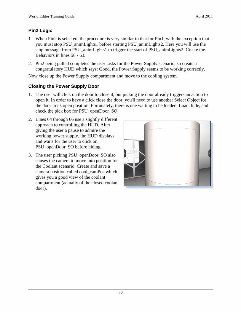
1. The user will click on the door to close it, but picking the door already triggers an action to open it. In order to have a click close the door, you'll need to use another Select Object for the door in its open position. Fortunately, there is one waiting to be loaded. Load, hide, and check the pick box for PSU_openDoor_SO.
2. Lines 64 through 66 use a slightly different approach to controlling the HUD. After giving the user a pause to admire the working power supply, the HUD displays and waits for the user to click on PSU_openDoor_SO before hiding.
3. The user picking PSU_openDoor_SO also causes the camera to move into position for the Coolant scenario. Create and save a camera position called cool_camPos which gives you a good view of the coolant compartment (actually of the closed coolant door).

World Editor Training Guide April 2011
31
FINE TUNINGTHE PSU SCENARIO
Before saving your project:
1. Go to the Hidden Transforms tab in the Geometry Browser and unhide the PSU_door.
2. Increment the version number and save your project.
3. Preview the project.
You'll notice some issues which need adjustment. In particular, when the bolt and tie-down shroud fly off the screen, the wait is too long before the cable connects to the battery. Look at lines 40 through 45 of the Tech Script: the psu_flyTimer controls the delay before the cable connects. Shortening that timer to 1.5 seconds fixes the issue.
Edit psu_flyTimer and change its start time to 1.5 seconds.
Also, the lights are a bit too difficult to see from the camera position. You need to create a new camera position which lets you see the lights a bit better, while still seeing the door. Remember to keep the door in view so that the user can click on the door in order to move to the Coolant scenario.
Interactive Numeric Entry of Camera Data
1. Select the Viewpoints tool in the Camera tool group.
2. At the bottom of your 3D display, a camera position editor appears. This editor is different from the Create a Viewpoint panel on the right-hand side. The Create a Viewpoint panel allows you to set values for a camera in order to save its position as a preset. The panel at the bottom of your 3D view gives you immediate feedback, moving your camera as soon as you enter the numbers.
3. Click in the fields in that panel and enter the following numbers:
4. In the Create a Viewpoint panel, click the Use Current Camera button.
5. Save this camera position as psu_camPos2.
6. Create a behavior so that when psu_flyTimer stops, the camera moves to psu_camPos2 over three seconds (Tech Script line 46).
7. Save and preview your project again.

World Editor Training Guide April 2011
32
HOW CAMERA POSITION CONTROLS THE SCENARIO
When the scenario starts from the beginning, the camera is at the security desk. Access to the payload is blocked by the select objects for the security doors. If the user had control of the camera and could move it past the security doors without opening them, the user would be able to entirely skip the security desk sequence. The select objects for the PSU compartment are active while the camera is still at the security desk. Similarly, the select objects for the coolant and sensors scenarios are active from the start of the scenario. The main tool used to control the flow of the scenario is the positioning of the camera.
Using the term “see” rather loosely (because the select objects are actually invisible) this sequence uses a principle that "if the user can't see it, they can't click on it." Technically, it would be more accurate to say that if an object is occluded then the user can't click on it. An occluded object is one which the camera has no line-of-sight to because something else is blocking the view - whether the occluded object is visible or not. But most people don't use the term "occluded" very often.
Remember the ESO covering the select object for the security doors at the security desk. In a similar way, the user cannot click on the select objects for the coolant scenario while at the PSU camera position, because the body of the payload is in the way. Camera position is a powerful tool in controlling what options are available to the user.
CHALLENGE ACTIVITY: FIX FLAWS IN THE PSU LOGIC
The PSU scenario as implemented assumes that the user follows all the steps in the correct order: opens the door, clicks on the battery cable tie-down shroud, clicks on pin 1 and pin 2, waits for the success HUD, and then closed the door.
In the PSU scenario, you placed Error Select Objects and created instructive HUD messages in anticipation of choices the user could make. However, the PSU scenario still contains some possible user actions which could interfere with the intended flow. A scenario designer needs to anticipate the choices a user might make, and create interactions to ensure that the scenario unfolds as planned.
For example, at the end of the PSU scenario, the user might see the PSU blinking lights, infer that the PSU is operational, and click on the door to close it before the congratulatory HUD is displayed. Although the camera has moved to the Coolant position, the HUD will still appear when the pre-success timer expires, but out of sequence. Because the command to hide the HUD was issued early when the user closed the door, the command to display the HUD remains in effect until it is replaced by the next HUD messages in the Coolant scenario.
In another faulty scenario, if a user inadvertently clicks on the invisible select object that closes the door, he or she could skip the PSU scenario entirely.
To challenge your knowledge:
• Implement preventative mechanisms for the examples listed above.
• Test the scenario to discover other logic flaws and implement methods to prevent them.

World Editor Training Guide April 2011
33
COOLANT
LOGIC FLOW FOR THE COOLANT SCENARIO
• The user must first release the coolant into the system. (Click the lower bolt first.)
• When the lower bolt is loosened, play an animation of coolant filling the view glass.
• After a short pause, show coolant gas venting from the nozzle.
• Show a HUD and make sure the user lets the coolant vent for 6 seconds to purge air.
• After coolant has vented for 6 seconds, the user shuts the upper valve, sealing the system (the gas stops venting).
TOPICS COVERED
• Using multiple text objects in one HUD
• Using the HUD nextPage command
• Using particle systems
INITITAL STEPS
Load the coolant_green model
BUILDING THE SCENARIO
1. Create the Behavior to open the coolant system door, as shown on Tech Script line 73.
2. Hide the coolant system door so that you can edit the contents of the coolant compartment. Remember to unhide this door before you save and preview your project.
3. Create the HUD and Behaviors from lines 74–76 relating to the second bolt. The user should not touch the second bolt until the coolant system vents.
4. cool_greenDelay is the timer which delays the green liquid from filling the display glass. Create the behaviors which start that timer and move the bolt (lines 77–79).
5. Define the animation for the object coolant_green, and save that animation as anim_CoolantRises. The range is from frame 249 to frame 625.
6. Create the Behaviors in lines 80 – 81. The end of the timer cool_greenDelay starts the animation, anim_CoolantRises. The end of the animation starts another timer, cool_mistVentDelay.
World Editor Training Guide April 2011
34
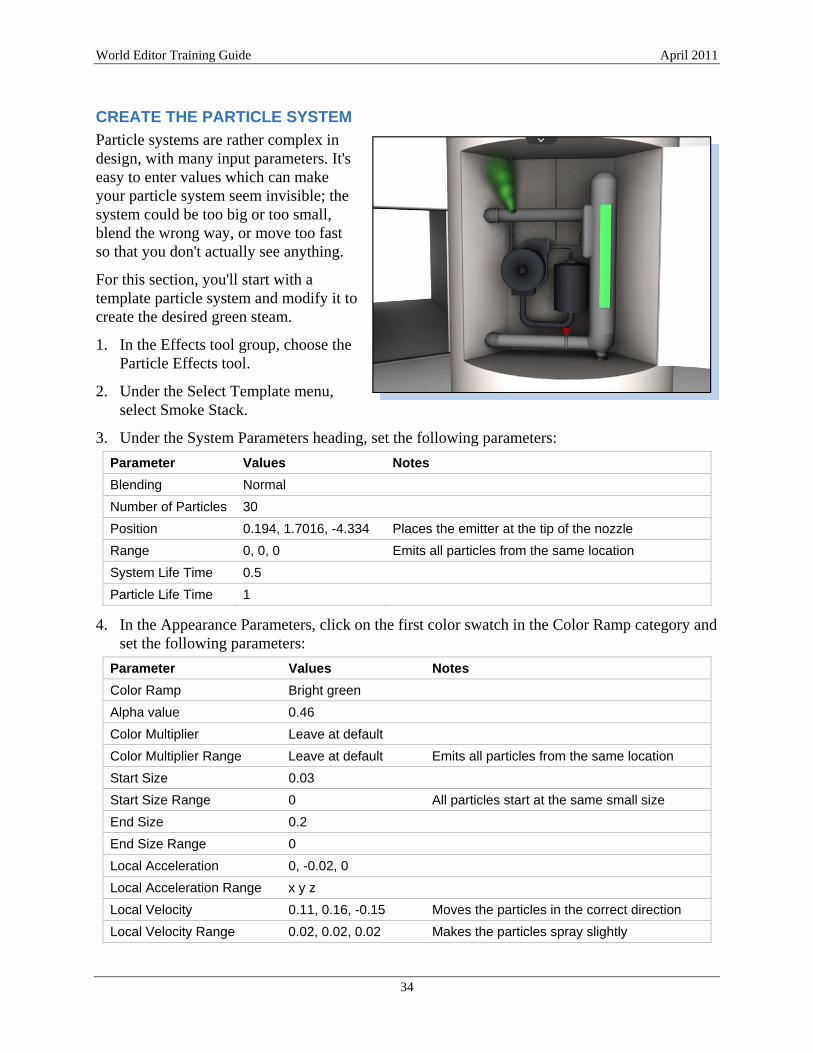
CREATE THE PARTICLE SYSTEM
Particle systems are rather complex in design, with many input parameters. It's easy to enter values which can make your particle system seem invisible; the system could be too big or too small, blend the wrong way, or move too fast so that you don't actually see anything.
For this section, you'll start with a template particle system and modify it to create the desired green steam.
1. In the Effects tool group, choose the Particle Effects tool.
2. Under the Select Template menu, select Smoke Stack.
3. Under the System Parameters heading, set the following parameters:
Parameter Values Notes
Blending Normal
Number of Particles 30
Position 0.194, 1.7016, -4.334 Places the emitter at the tip of the nozzle
Range 0, 0, 0 Emits all particles from the same location
System Life Time 0.5
Particle Life Time 1
4. In the Appearance Parameters, click on the first color swatch in the Color Ramp category and set the following parameters:
Parameter Values Notes
Color Ramp Bright green
Alpha value 0.46
Color Multiplier Leave at default
Color Multiplier Range Leave at default Emits all particles from the same location
Start Size 0.03
Start Size Range 0 All particles start at the same small size
End Size 0.2
End Size Range 0
Local Acceleration 0, -0.02, 0
Local Acceleration Range x y z
Local Velocity 0.11, 0.16, -0.15 Moves the particles in the correct direction
Local Velocity Range 0.02, 0.02, 0.02 Makes the particles spray slightly

World Editor Training Guide April 2011
35
The Range values control the amount of random deviation from another set value. In this case, the Range setting alters to Local Velocity by as much as 0.02.
5. Skip the rest of the particle effect parameters, and go to the bottom of the Create Particle Effect panel.
6. Enter cool_ventParticles for the Particle Effect Name, and click Save.
7. Create the Behavior on line 82 to display the particle system at the end of the cool_mistVentDelay timer.
CREATE THE MULTI-PAGE HUD
So far, you have created single-page HUDs. When you create a HUD and create more than one page within it, you can use the nextPage and prevPage commands to move between pages of that HUD. For the countdown timer, you'll create a multi-page HUD and use the nextPage command each time a second elapses.
To get a different text effect for the numbers which appear in the countdown, you'll also create multiple text objects for each page of the HUD. Because a multi-page HUD will, by default, start by showing its first page, you'll create the countdown pages in reverse order. Using this method means you don't have to set the HUD to a specific page before displaying it.
Create Page 1
To create the background text:
1. Create a HUD named cool_ventAdvisorHUD and create a Page for that HUD. The page is automatically named Page 1.
2. Create a text object for that page, with a position of 353 by 320.
3. Set the Color to 1, 1, 0.6, 1, and the text to 14-point Helvetica.
4. Set the Style to Bold, the Alignment to Left, and enter this Text:
To purge the system of air, allow the system to vent for ______ seconds. (Leave 6 spaces between "for" and "seconds.")
5. Set the Width to 150 and save the text object.
To create the foreground text:
1. Press the Add Text button again to create a second Text object for Page 1.
2. Set the position to 332 by 374.
3. Set the Color to a bright orange,
To make it easier to set a consistent orange color, pick a numeric value which you can type into the R, G, and B numeric fields at the bottom of the color picker. The example scenario uses the values 240 150 40. After typing in a number, hit the Tab key twice to get to the next numeric input field.

World Editor Training Guide April 2011
36
4. Set the size to 20, the font to Helvetica, and the Style to Bold.
5. Set the Alignment to Center, and enter the number 6 for the text.
6. Set the Width to 30, and Save Text as sec6_text.
Create Pages 2 – 6
In the HUD Outline, at the bottom of the Heads-Up Display tool, your current page is highlighted in blue.
1. Click on the level above, which is labeled cool_ventAdvisorHUD.
2. In the top portion of that tool panel, click the Add Page button to add a new page.
3. Create Page 2 almost exactly as you created Page 1, except enter the number 5 instead of 6.
4. Continue with this pattern through Page 6, which will show only 1 second left.
Finish the Coolant Scenario
Once you have created the behavior cool_start_sec7 on lines 83, you can use the Duplicate button to make the creation of other behaviors much easier.
1. Click on the Duplicate button to create a Copy of cool_start_sec7.
2. Click on the edit button for that new behavior.
When you edit the trigger, the menu will already be on the stop message from cool_mistVentDelay.
3. Open cool_ventSec7 and select its stop message.
Similarly, the action menu will be centered on cool_ventSec7 start.
4. Select the start message from cool_ventSec6 instead.
5. Name this behavior cool_start_sec6.
6. Duplicate cool_start_sec6 and edit it to become cool_start_sec5.
7. Repeat this pattern to create the behaviors on lines 86, 88, 90, 92, and 94.
Filtering in the Behaviors List
To keep from having to search through so many pages of behaviors, you can enter a pattern into the filter field (the field with the magnifying glass icon) and type in a pattern.
If you filter for the behavior names which start with cool_, you won't see duplicated behaviors you created; duplicated behavior names start with Copy of. However, if you filter using the Trigger name, you will see your countdown behaviors and the duplicates as well.
Click in the filter field, type Timer.cool, and look at the filtered list of behaviors.
To see only the behaviors that are related to the coolant venting sequence, add an underscore with the word vent so that the filter pattern is now Timer.cool_vent. You will see a more precise listing of related behaviors.

World Editor Training Guide April 2011
37
Use the nextPage Command
1. Create the behavior on line 85 of the Tech Script. This automatically shows page 1 of the HUD.
2. Duplicate cool_show_sec6HUD.
3. Edit the duplicate, setting the trigger to be the stop signal from timer cool_ventSec6 and the action to be nextPage function for cool_ventAdvisorHUD. The nextPage function causes the HUD to now display page 2, which has the countdown at 5 seconds.
4. Save this behavior as cool_show_sec5HUD.
5. Repeat this pattern to create the behaviors on lines 89, 91, 93, and 95.
6. Create a HUD which says “Good - the coolant system seems to be sealed. Now prepare the sensors.” Name it cool_successHUD.
7. Create a good camera position (sens_camPos) so you can see the Sensors compartment.
8. Create the behaviors from lines 96 through 106. Those behaviors are very similar to what you have created so far.
Question: Why can't I create a generic timer with a duration of one second, and simply reset and re-use that same timer repeatedly for the countdown?
Answer: You need a unique trigger for the end of each second. Otherwise, the end of the timer with 5 seconds left would look identical to the end of the timer with 1 second left. To have six similar events occur in sequence, you need six unique timers.

World Editor Training Guide April 2011
38
THE SENSORS SCENARIO
SPECIFICATIONS FOR THE SENSORS SCENARIO
In this scenario, the user must connect the sensor module to its receptacle before attempting to measure the resistance between the recording modules. After connecting the sensor module, the user should wiggle it to verify that it has properly snapped into place.
TOPICS COVERED
• Using a draggable manipulator
• Using nested animations
INITIAL STEPS
1. Load these objects: multimeter, sens_bananaClipSocket_ESO, and sensors.
2. Because the multimeter and sensors would be visible from other camera positions, create the behaviors on lines 8 and 9 to initially hide them.
3. In the Browser Tree, select sens_bananaClipSocket_ESO, hide it, and set it to be pickable.
Note: This only works for sens_bananaClipSocket_ESO and not for sens_bananaClipSocket_ESO_root.
4. Define the sens_flyIn animation for the sensors object. (This is in the Animation tool group, using the Animator tool.) This animation lasts from frame 0 to frame 145.
5. Define the anim_multiFlyIn animation for the multimeter from frame 0 to 150.
6. Create a 3-second timer and save it as sens_successTimer.
7. Create the behavior on line 111 so that the sensors become visible when the camera arrives at sens_camPos.
8. Create the behavior on line 112 which opens the sensor compartment door.
CREATE THE HUDS
1. Create a HUD named sens_errorHUD which says: “You can't measure the resistance across the sensor connectors until you first connect the sensor unit.”
2. Create sens_successHUD which says: “Very good! All instruments check out appropriately. The payload is ready for flight.”

World Editor Training Guide April 2011
39
CREATE THE NEEDLE ANIMATION
A keyframed animation wiggles the needle of the multimeter after it has been rotated to the proper reading. If the animation had also included the rotation from zero up to the desired value, the animation would not have been repeatable. To control the value which the needle reads and retain the benefit of the keyframed animation, you'll play the keyframed animation on an object which has already been rotated by a turn function.
1. Go to the Animator tab, and define an animation for the multimeter from frames 152 to 450.
2. Add a loop and set its repeat value to -1 so that it loops constantly.
3. Save this Animation as anim_multiNeedle.
FLY THE SENSOR MODULE INTO PLACE
1. Create a 4-second time called sens_errorTimer.
2. Create a behavior such that selecting sens_bananaClipSocket_ESO causes sens_errorHUD to display. (sens_show_errorHUD on line 113)
3. Duplicate sens_show_errorHUD and set the duplicate to start sens_errorTimer. Save that behavior as sens_start_ErrorTimer (line 114).
4. Create the behavior on line 115 to hide the HUD when the timer runs out.
5. Create the behavior on line 116 which flies the sensor module into place when its red connector (group3_connector) is picked.
CREATE A MOVABLE INTERACTION
1. Create a HUD called sens_moduleHUD which says “Wiggle the sensor unit to verify that the mounts have latched properly.”
Now you will create a behavior triggered by the stop message from sens_flyIn.
2. For the action, open the transforms under the sensors citizen and locate the setMovable function under the sensor node. (do not assign this Action to sensor_connector by mistake)
3. Enter the letters yz (must be lower case) for the plane field, and set the limits to: -0.001 0.001 -0.001 0.001. The ordering of those limit parameters is: Minimum in the U direction (horizontal), Maximum in U, Minimum in V (vertical), Maximum in V.
4. This behavior makes the sensor module able to be dragged with the mouse by a total of 2 mm on the YZ plane.
5. Create the behavior on line 119 so that sensors / transforms / sensor_g / sensor / messages /
move hides the HUD. The move message is sent when a movable object is dragged with the mouse.
6. Duplicate sens_hideModuleHUD and set the Action of the duplicate behavior to set sens_bananaClipSocketESO to not be pickable. No recursion is needed for this setPickable.

World Editor Training Guide April 2011
40
FLY THE MULTIMETER INTO PLACE
Before you fly the multimeter into place using its keyframed animation, you will need to unhide it. Because of the structure of the multimeter 3D object, multiple steps will be required to unhide it properly.
In the Geometry Browser Tree, open multimeter / Transforms / multimeter_root / multimeter_G so that you can see the contents of that transform.
Notice that SO_meter is under the same parent node (multimeter_G) as the parts of the meter which are meant to be visible. If you recursively set multimeter_G to be visible, it also sets SO_meter to be visible. You will need to add an extra behavior to re-hide SO_meter after you unhide multimeter_G.
1. Create the behavior on line 110. This behavior unhides multimeter_G when the camera arrives at sens_camPos.
2. Create the behavior on line 121 which hides SO_meter before the multimeter is flown into the camera view.
ROTATE THE MULTIMETER NEEDLE
1. Create the behavior on line 122 which flies the multimeter into place.
2. In the Browser Tree, open multimeter / needle_animG.
The transform called needle_animG has the keyframed animation data. The lowest-level transform is called needle.
3. Create the behavior on line 123 so that picking the select object rotates the needle node negative 50 degrees on its Y axis over 1 second.
4. Create the behavior on line 125 so that when the needle finishes turning, it makes the select object no longer pickable. This prevents over-rotating the needle.
5. Create the behavior on line 126 so that the stop message from the turn also triggers the needle animation loop to begin playing.
6. Create the behaviors on lines 124 and 127 to finish the Payload project.

World Editor Training Guide April 2011
41
SUPPLEMENTAL INFORMATION
CONCEPT INFORMATION ABOUT THE 3D NODAL HIERARCHY
Similar in concept to nodes in a flow chart, a node in a 3D application is anything which can receive and/or send information. A 3D model has its shape stored in one type of node, with at least one transform node. Transform nodes are used in Kuda to translate (move), rotate, and scale objects, as well as to control their visibility and pickable state. A number of 3D models, each with their own transform, can be grouped under another transform node.
A car, which is made of many movable objects, is a good example which would benefit from a group transform node. The wheels need to be able to turn, the doors need to be able to rotate open, but when the car moves forward the doors and wheels should move with the car body. To accomplish this, you would make the doors and wheels children of the transform which moves the car body.
Timers are also nodes. Timers receive signals to start, stop, and reset, as well as sending messages when they start and stop. As you build the payload project, you will see progressively more items in the Trigger and Action menus which have a C for Citizen.
USING KUDA'S JAVASCRIPT LIBRARIES
The World Editor is one component of the Kuda suite of tools. Kuda also provides Javascript libraries that allow you to program more sophisticated scenarios than the World Editor alone can support. For examples and more information, go to the websites
http://code.google.com/p/kuda/wiki/Samples http://stable.kuda.googlecode.com/hg/public/doc/index.html

![Digital Camera - Panasonic · [ENGLISH] Basic Operating Instructions Digital Camera Model No. DMC-SZ8 Please read these instructions carefully before using this product, and save](https://img.pdfslide.net/doc/110x75/5c5fb55209d3f25d398b5154/digital-camera-panasonic-english-basic-operating-instructions-digital-camera.jpg)