Embed Size (px)
Citation preview
WORLD METEOROLOGICAL ORGANIZATION
COMMISSION FOR BASIC SYSTEMS
OPAG ON INFORMATION SYSTEMS AND SERVICES
MEETING OF THE EXPERT TEAM ONDATA REPRESENTATION AND CODES
FINAL REPORT
ARUSHA, 17-21 FEBRUARY 2003

EXECUTIVE SUMMARY
The Meeting of the Expert Team on Data Representation and Codes (ET/DR&C) was held, at the kind invitation of the United Republic of Tanzania, in Arusha, from 17 to 21 February 2003.
The Team reviewed the status of validation tests for the new FM 92 GRIB Edition 2 encoding/decoding. Further validation tests and experimental exchanges were recommended for some templates: PDT 4.10 and 4.14, GDT 3.1000/1100/1200 and PDT 4.1000/1001/1002/1100/1101. The Team proposed, for experimental testing, the addition of two new compression schemes based on JPEG 2000 and PNG. Clarifications of regulations for scaling, use of local Tables and local Templates, and for spatial differencing were developed. The guide for GRIB Edition 2 was finalized.
Several Centres reported on experimental and operational exchanges of fields in GRIB2. Japan Meteorological Agency (JMA) had a separate GRIB2 encoder for specific generated products and a decoder for limited products. Provision of three and six month ensemble forecast products in GRIB2 should start next autumn for national and international users; new products in field form would be considered in GRIB Edition 2. NCEP has both a Fortran 90 and C version of an encoder/decoder. An experimental project (called National Digital Forecast Database) managed by NWS/TDL made use of GRIB2. ECMWF should start migration to GRIB2 and provide EPS probabilities on the GTS in 2003. A decoder will be available to decode these products. EUMETSAT is generating Cloud mask products in GRIB2. Satellite images will also be available in GRIB2. A decoder for this type of data is available to users upon request. It is still to be included in the PUMA work-station.
The Team agreed to define a new Common Code Table C-12 for recording Sub-Centre entries linked to originating Centres. The Team agreed that recording of Sub-Centres in the WMO Manual should be a recommended practice, and recommended also the allocation of entries in Table C-11 for all non-listed NMCs, RSMCs, RTH, etc.
The Team discussed, finalized and recommended additions of descriptors to BUFR Tables. Descriptors with pre-operational status were recommended for oceanographic data and for new satellite data, including ENVISAT and AIRS satellites. A proposal to encode in BUFR all SIGMET data (to be validated), including description in 3-D of meteorological features, was finalized. The Team also recognized the possible usefulness of a separate Master Table for satellite data to help managing the continuously increasing number of related descriptors. A proposal will be coordinated by EUMETSAT for the next meeting of the ET/DR&C.
The recommended BUFR templates for transmission of traditional observations were revisited by the Team. For PILOT and TEMP data, it was agreed to indicate by a note that the first time corresponds to the nominal time of observation, and to indicate that the first latitude and longitude are those of the launching site. Time increment in seconds and increments of high accuracy latitude and longitude will be reported at each level. These additions will satisfy requirements of high resolution modeling. In the BUFR/CREX template for SYNOP and SYNOP MOBIL data, it was agreed to qualify the descriptor 0 20 014 as “height of top of the clouds above mean sea level” and to express the significant cloud layers using delayed replication.
The Team considered the impact that a change to a new edition in November 2005 might have on the migration process. The Team agreed to debate on this issue during the coming year to reach a final decision at its next meeting.
The Team noted that new experimental or operational exchange of new BUFR data was taking place. Experimental transmission of Buoy, BATHY and TESAC data by Service Argos in BUFR should start during 2003. JMA is planning to disseminate SHIP data in BUFR, and is already disseminating wind profiler data in BUFR. Météo-France will soon disseminate JASON 1 satellite data in BUFR. Within the EUMETNET PWS-GTS project, CHMI (Czech Republic), KNMI (Netherlands) and SHMI (Slovakia) are disseminating AWS observations in BUFR. DWD (Germany) will start in July 2003. As part of its EARS (EUMETSAT ATOVS Retransmission Service) project, EUMETSAT encodes in BUFR the level 1c ATOVS data.
i
In order to correct a weakness in the text of some regulations, the Team agreed to clearly specify, in code forms FM 71, FM 72, FM 73, FM 75, FM 76, FM 81, FM 82 and FM 83 that, when several reports are included in a bulletin then each report inside the bulletin does not need to have the code name and MMJJJ indicated.
The Team proposed a potential list of keynote lecturers and defined a programme for a workshop on use of XML in meteorology.
To facilitate the implementation of new descriptors in Code Tables, the Team recommended that the Secretariat create a MS-Word merged file of all Table B and Table D entries, with an indicator attached to each entry: version number, or pre-operational or for validation. Another file in ASCII format for direct computer program processing will be created with the help of a data processing centre.
The Team agreed that samples of BUFR and CREX Templates will be placed in an Attachment to the Manual, and should include links to the general reporting practices. Appropriate common sequences may be generated as required. The Team recommended this activity to be performed under the responsibility of the WMO Secretariat. A consultant might be hired for a few weeks to finalize the task. The new Annex on reporting practices and the Templates, once finalized, will have to be reviewed by appropriate Teams of CBS.
ii
CONTENTS PAGE
1. ORGANIZATION OF THE MEETING.............................................................................................................11.1 Opening of the meeting.................................................................................................................................. 1
Annex to 1.1.1 - Participants list....................................................................................................................131.2 Approval of the agenda................................................................................................................................... 12. GRIB CODE FORM........................................................................................................................................ 12.1 STATUS AND COORDINATION OF VALIDATION TESTS FOR GRIB 2 ENCODING/DECODING .................12.2 VALIDATION OF SPECIAL TEMPLATES FOR THE TRANSMISSION IN GRIB 2 OF CROSS-SECTIONS
AND HOVMÖLLER TYPE DIAGRAMS...........................................................................................................22.3 ADDITION OF NEW COMPRESSION SCHEMES..........................................................................................2
Annex to 2.3.5.............................................................................................................................................. 142.4 OTHER ADDITIONS OR MODIFICATIONS TO GRIB EDITION 2...................................................................32.4.1 New regulation related to scaling....................................................................................................................3
Annex to 2.4.1.2........................................................................................................................................... 182.4.2 Albers equal-area projection in GRIB2............................................................................................................3
Annex to 2.4.2.............................................................................................................................................. 182.4.3 Need for a Note on use of Local Tables or Templates in GRIB Edition 2 .........................................................3
Annex to 2.4.3.............................................................................................................................................. 192.4.4 Addition of note to DRT 5.2 and 5.3................................................................................................................3
Annex to 2.4.4.............................................................................................................................................. 202.5 REPORT ON EXPERIMENTAL AND OPERATIONAL EXCHANGES OF FIELDS IN GRIB2............................43. BUFR AND CREX.......................................................................................................................................... 43.1 ADDITIONS FOR SATELLITE DATA..............................................................................................................43.1.1 ENVISAT data................................................................................................................................................ 4
Annex to 3.1.1.............................................................................................................................................. 213.1.2.1 Additional entries for AIRS satellite data in BUFR...........................................................................................4
Annex to 3.1.2.1........................................................................................................................................... 363.1.2.2 Other additional entries for satellite data in BUFR..........................................................................................4
Annex to 3.1.2.2........................................................................................................................................... 393.2 UPDATED PROPOSAL FOR ENCODING SIGMETS IN BUFR.......................................................................5
Annex to 3.2.2.............................................................................................................................................. 403.3 NEW ORIGINATING CENTRES AND SUB-CENTRES....................................................................................5
Annex to 3.3................................................................................................................................................. 463.4 OTHER ADDITIONS TO BUFR/CREX............................................................................................................53.4.1 Additions for oceanographic data....................................................................................................................5
Annex to 3.4.1.............................................................................................................................................. 473.4.2 BUFR regulations: Points which require clarification........................................................................................5
Annex to 3.4.2.............................................................................................................................................. 503.4.3 Identification of ship's movement in the BUFR template for SHIP data.............................................................6
Annex to 3.4.3.............................................................................................................................................. 503.4.4 BUFR Templates for PILOT and TEMP data with identification of radiosonde drift...........................................6
Annex to 3.4.4.............................................................................................................................................. 513.4.5 BUFR/CREX template for SYNOP and SYNOP MOBIL data...........................................................................5
Annex to 3.4.5.............................................................................................................................................. 553.5 ADDITIONS RELATED TO A NEW EDITION OF BUFR..................................................................................63.5.4 Full date in BUFR........................................................................................................................................... 7
Annex to 3.5.4.............................................................................................................................................. 603.5.5 Other addition with a new edition....................................................................................................................7
Annex to 3.5.5.............................................................................................................................................. 603.6 IMPLICATIONS OF A NEW EDITION OF BUFR.............................................................................................73.7 IMPLEMENTATION OF EXPERIMENTAL EXCHANGES OF OBSERVATIONS IN BUFR/CREX.....................74. MODIFICATIONS TO TRADITIONAL ALPHANUMERIC CODES...................................................................84.1 MODIFICATIONS TO AERONAUTICAL METEOROLOGICAL CODES...........................................................84.2 HARMONIZATION OF REGULATION FOR REPORT HEADER......................................................................85. FINALISING GUIDE TO GRIB EDITION 2......................................................................................................9
Annex to 5.................................................................................................................................................... 616. WORKSHOP ON USE OF XML AND DEFINITION OF METEOROLOGICAL OBJECTS IN XML...................97. MANUAL ON CODES.................................................................................................................................. 107.1 IMPLEMENTATION OF THE PROCEDURES FOR MODIFICATION TO TABLE DRIVEN CODES................10
Annex to 7.1.2.............................................................................................................................................. 637.2 PROPOSED MANUAL ON REPORTING PRACTICES..................................................................................118. ACTIONS PLAN........................................................................................................................................... 118.1 NEXT MEETING.......................................................................................................................................... 118.2 TASKS......................................................................................................................................................... 119. CLOSURE OF THE MEETING.....................................................................................................................12List of acronyms...................................................................................................................................................... 64
1
REPORT OF THE MEETING OF THE EXPERT TEAM ONDATA REPRESENTATION AND CODES
(Arusha, 17-21 February 2003)
1. ORGANIZATION OF THE MEETING
1.1 OPENING OF THE MEETING
1.1.1 At the kind invitation of the United Republic of Tanzania, the Meeting of the Expert Team on Data Representation and Codes (ET/DR&C) took place at Mount Meru Hotel in Arusha from 17 to 21 February 2003 (the participants’ list can be found in the Annex to this paragraph). The Meeting was opened on Monday 17 February at 9.30 a.m. by Mr Mohamed Matitu, Manager of International Relations in Tanzania Meteorological Agency (TMA). Mr Matitu welcomed the Experts and recalled the importance of the work of the Team. He stressed that it was the first time this Expert Team meets in a developing country. It was an hopeful sign for the WMO strategy to share the advanced knowledge and technology with developing countries, especially the African countries. Mr Matitu wished to all Experts a good stay in Tanzania.
1.1.2 The representative of the WMO Secretariat thanked Tanzania for hosting the meeting. He thanked Tanzania Meteorological Agency for providing excellent hospitality and facilities and having work hard for the organisation and logistic of the meeting. He thanked especially the local organisers from TMA, Mr Matitu and Mr Scylla Sillayo (member of the Expert Team) and all the other staff involved, for their good work. The Team had several challenging tasks on the agenda, in particular: further refine GRIB 2 Tables and Templates, finalize the GRIB 2 Guide, consider the need for a new edition of BUFR and plan a workshop on XML, in additions to the usual examination of the set of requests for additions to the Codes Tables.
1.1.3 Mr Jean Clochard, Chairman of the Team, after having thanked Tanzania, welcomed the participants. He then led the Team with diplomacy and efficiency.
1.2 APPROVAL OF THE AGENDA
The Team agreed to the content of the agenda as proposed (see Table of Contents in front).
2. GRIB 2 CODE FORM
2.1 STATUS AND COORDINATION OF FINAL VALIDATION TESTS FOR GRIB 2 ENCODING/DECODING
2.1.1 Templates referred in the Code Manual as “not validated” were revisited. In 2001 and 2002, several new templates were defined at ET/DR&C level, and some also were fixed. What follows is a result of a recent survey which included answers received from NCEP, ECMWF, JMA and UKMO.
2.1.1.1 EPS related templates
- Product Definition Templates 4.9, 4.11, 4.12 and 4.13 were cross-validated between NCEP, ECMWF and JMA.
- PDT 4.10 and 4.14: no validation work was performed. - PDT 4.3 and 4.4 were fixed in 2002 (addition of missing information describing properties
of the cluster) but it is not certain that existing encoding/decoding packages have been adjusted accordingly, except at USA/NDFD.
1

2.1.1.2 Templates for support of non-horizontal grids
These templates were designed in 2001 to handle cross sections, time sections and Hovmöller-type diagrams. Up to now, only NCEP (USA) has implemented these templates.
2.1.2 Proposal
The Team recommended as an editorial change to remove the preliminary note in the Manual attached to Template 4.9 since this Template is now validated. The Team urged Centres to validate PDT 4.10 and 4.14 in order to get more results/work on these templates. The Team reminded concerned Centres that PDT 4.3 and 4.4 have changed.
2.2 VALIDATION OF SPECIAL TEMPLATES FOR THE TRANSMISSION IN GRIB 2 OF CROSS-SECTIONS AND HOVMÖLLER TYPE DIAGRAMS
The Team asked that at least a second Centre implement GDT 3.1000/1100/1200 and PDT 4.1000/1001/1002/1100/1101 to enable cross-validation, and look for assessment from users who have an interest in these templates.
2.3 ADDITION OF NEW COMPRESSION SCHEMES
2.3.1 GRIB2 was designed to be extensible and is now capable of storing satellite and radar data, which are inherently images and thus may benefit from being encoded into a standard graphic format. In addition, numerical model data can also be effectively encoded with an image-encoding algorithm since, after the model gridpoint data is scaled to retain the desired precision and the minimum value is subtracted out, the resulting grid can be thought of and processed as a grayscale image.
2.3.2 Throughout the past many years, much research and development has been conducted regarding image compression and standardization of graphic formats, so it seems as though it should be possible to take advantage of these results for incorporation as new compression techniques within GRIB2. Two prominent standards are supported by the International Organization for Standardization (ISO) and the NCEP (USA) proposed to the Team methodologies by which they might be incorporated for use in GRIB2. These two standards are JPEG 2000 (http://www.jpeg.org/JPEG2000.html) and PNG (http://www.libpng.org/pub/png), and they were chosen not only because of their inclusion in ISO/IEC international standards, but also because of their demonstrated effectiveness on sample data as well as their intent to be license and royalty free. This last point is currently the subject of some further investigation, as obviously it will be necessary to adhere to any requirements that may be imposed by ISO or other scientific bodies in exchange for being allowed to make use of their work in the creation of new templates for GRIB2. The current understanding is that such requirements would likely be limited to the inclusion of footnotes and/or certain disclaimers within any such GRIB2 templates.
2.3.3 NCEP indicated that several simulations had already been run comparing the JPEG 2000 (with lossless compression) and PNG compression algorithms against the current GRIB2 packing methods. The tests were run on various output fields from the NCEP 12km ETA model, and the results showed an impressive savings of storage space when using the two new methods, albeit at the expense of additional system processing time that was, in most cases, quite significant.
2.3.4 The following two standards were considered by the Team.
2.3.4.1 JPEG 2000
The JPEG 2000 image coding system uses wavelet transforms and subsequent arithmetic coding to encode an image. The compressed image is stored in the code stream syntax described in Part 1 of the standard (ISO/IEC 15444-1:2000). The JPEG 2000 standard contains both lossless
2
and lossy compression algorithms allowing users the option of specifying an increased compression rate in exchange for some noise in the data.
2.3.4.2 Portable Network Graphics (PNG)
The PNG encoding algorithm applies one of several invertible filters to each scanline of an image, and then subsequent compression is obtained using the zlib (http://www.gzip.org/zlib/zlib.html) deflate algorithm. The PNG specification is currently under consideration by ISO/IEC JTC 1/SC24. PNG image compression is lossless.
2.3.5 The team agreed that the two templates listed in Annex to this paragraph be used for validation and experimental testing.
2.4 OTHER ADDITIONS OR MODIFICATIONS TO GRIB EDITION 2
2.4.1 New regulation related to scaling
2.4.1.1 Within GRIB edition 2, some entities in sections 3 (Grid Description Section) and 4 (Product Description Section) are documented in a scaled way. A typical example may be given by the value associated to a vertical level. This was defined to avoid use of decimal shifted units; and also to avoid floating-point descriptors, which may lead to ambiguities. The description of these entities is a pair of descriptors: a scaled factor (on a single octet), and a scaled value (on four octets); however, it is not indicated in the Manual how to use it precisely. There is still an ambiguity on the sign convention for this factor.
2.4.1.2 The Team therefore agreed to add a new general regulation (considered as editorial change since it only adds a clarification) as listed in Annex to this paragraph.
2.4.2 Albers equal-area projection in GRIB2
In GRIB edition 2 Manual, the Code Table 3.1 (Grid Definition Template Number) exhibits for code entry 30 (Lambert conformal) a note stating that it is “also called Albers equal-area”. As mentioned by a user from USA (from the geographical community) the note referred to was clearly erroneous. Lambert conformal projection preserves angles, whilst Albers’s preserves areas; such properties may not be reached at the same time, except for very simple transformations. The confusion came from the fact that these projections share the same descriptors list. The Team then agreed to:
- remove the wrong note for entry 30 in Code Table 3.1- add a new entry 31 in Code Table 3.1, called “Albers equal-area”- Introduce a new template 3.31- submit these changes as listed in Annex to this paragraph for pre-operational
implementation.
2.4.3 Need for a Note on use of Local Tables or Templates in GRIB Edition 2.
Following a request from Japan, the Team agreed to add a Note clarifying the use of Local Tables or Templates in GRIB Edition 2 (see Annex to this paragraph).
2.4.4 Addition of note to DRT 5.2 and 5.3
The Team agreed that to avoid misunderstanding such as raised in the GRIB2 guide for spatial differencing, a note should be added to these templates (see Annex to this paragraph).
3
2.5 REPORT ON EXPERIMENTAL AND OPERATIONAL EXCHANGES OF FIELDS IN GRIB2
NCEP has both a Fortran 90 and C version of an encoder/decoder. An experimental project (called National Digital Forecast Database) managed by NWS/TDL makes use of GRIB2, with a participation from NCEP.
ECMWF should start migration to GRIB2 and provide EPS probabilities on the GTS in 2003. A decoder will be available to decode these products.
JMA has separate encoder for specific generated products and decoder for limited products, and an extra package will be developed for domestic use of products of very short range forecast on precipitation. Provision of 3 and 6 months ensemble forecast products should start next autumn for national and international users. New products in field form would be considered in GRIB edition 2.
EUMETSAT is generating Cloud mask products in GRIB2. Satellite images will also be available in GRIB 2. A decoder for this type of data is available to user at request. It is still to be included in the PUMA work-station.
3. BUFR AND CREX
3.1 ADDITIONS FOR SATELLITE DATA
3.1.1 ENVISAT data
In March 2002, ENVISAT satellite was successfully launched by ESA. ENVISAT is now completing its commissioning phase. The satellite carries a number of instruments among which ASAR, MERIS, AATSR, RA-2, GOMOS, MIPAS and SCIAMACHY are of meteorological interest. ECMWF developed software to extract ENVISAT PDS data and create BUFR data containing subset information available in the original data set. At the same time some evaluation of SCIAMACHY, MIPAS, GOMOS and ASAR data has been done at ECMWF. The Team agreed to the corresponding additions in BUFR Tables as listed in Annex to this paragraph and urged centres concerned to finalize validation of these entries, in order to declare them pre-operational since the data are already available for exchange.
3.1.2 Other Satellite data
3.1.2.1Additional entries for AIRS satellite data in BUFR
During the past couple of years, much work has been done to represent and exchange AIRS satellite data in BUFR. In order to assist in this effort, a Table B descriptor was proposed last year as “ALLOCATED ENTRIES (AWAITING VALIDATION)”. Since then, and using the sequences described below (although not the actual Table D numbers), successful data exchange had taken place between centers in the U.S.A., Canada, and Europe (among others), and the usefulness of the below descriptors has been demonstrated. Therefore, the Team now requested that the descriptors as listed in Annex to this paragraph be approved for “PRE-OPERATIONAL” status.
3.1.2.2 Other additional entries for satellite data in BUFR
4
The Team agreed to a request by NCEP USA for new BUFR table entries for use with certain types of satellite data. Some entries (see Annex to this paragraph) are ready for “PRE-OPERATIONAL” status, while others are requested only as “ALLOCATED ENTRIES (AWAITING VALIDATION)”.
5
3.2 UPDATED PROPOSAL FOR ENCODING SIGMETS IN BUFR
3.2.1 Following an original joint proposal presented by the representatives from Australia and ICAO for the encoding of volcanic ash SIGMET messages in BUFR, the U.S. National Weather Service’s Aviation Weather Center proceeded to expand the proposal to include a methodology for the encoding of all types of SIGMET messages, including those for tropical cyclones, turbulence, icing, etc. However, one major issue still remained to be decided, and that was the issue of whether to allow for the ability to define volumes of any shape as a SIGMET target region, versus only being able to define volume regions which, when viewed from above, have sides that are always perpendicular to the ground between two 0-07-010 flight levels (i.e. base and top). In other words, it might be useful to be able to use the code figure “3” within 0-08-007 and thereby define a sequence of points describing 3-D volume. The current ICAO Annex 3 regulations do not allow for such odd-shaped objects; however, the US Aviation Weather Center has the intention to soon make such a proposal to ICAO, so it is useful to allow for this possibility now rather than to create some new descriptors and sequences that may soon become obsolete.
3.2.2 The proposal of the Team (see Annex to this paragraph) was simpler but retained the ability to define volumes of any reasonable shape as a SIGMET target region. This approach allowed for the specification of volumes defined by a sequence of horizontal sections on flight levels. The Team felt that the overall proposal was ready to be validated, and requested members of the ET/DR&C, and also the UK Met Office as a WAFS center, to assist the US Aviation Weather Center personnel in this task through the generation and exchange of various test messages encoded according to the specifications of this proposal.
3.3 NEW ORIGINATING CENTRES AND SUB-CENTRES
Following a request from USA to add a list of Sub-Centres to US NWS, NCEP, the Team agreed to define a new Common Code Table C-12 for recording Sub-Centres entries linked to originating centres (see Annex to this paragraph). This table being just a new way of presenting information will be considered as additional entries and can be included in the next supplement to the Manual (pre-operational). However, the Team raised the question of mandatory reporting and recording of Sub-Centres in the WMO Manual. The Team agreed that it should be a recommended practice and agreed to add a note to Table C-12 saying that Sub-centres should be recorded in the Manual on Codes and that entries should be given to the WMO secretariat. The Meeting recommended also the allocation of entries in Table C-11 for all non-listed NMCs, RSMCs, RTH, etc.. according to English alphabetical order.
3.4 OTHER ADDITIONS TO BUFR/CREX
3.4.1 Additions for oceanographic data
The Team approved a set of new BUFR descriptors requested by the Data Buoy Cooperation Panel (DBCP) for buoy data in BUFR and by the Ship Of Opportunity Programme (SOOP) to transmit XBT data. The proposed additions to code tables would need validation, except the new entries for Common Code tables which can be seen as pre-operational. The additions can be found in Annex to this paragraph.
3.4.2 BUFR regulations: Points which require clarification
Six proposals to amend some notes and regulations were submitted by Chris Long from UKMO. These additions were examined by the Team who approved the first one as listed in Annex to this paragraph. This change should be considered as editorial since it simply adds clarification to the existing regulation. However, for the five other amendments the Team considered they deserved further studies in relation to the current practices.
6
3.4.3 Identification of ship's movement in the BUFR template for SHIP data
The Team considered a proposal from Eva Cervena following a request from the Royal Netherlands Meteorological Institute (KNMI) to qualify or rename the descriptors for Direction of motion of moving observing platform and for Speed of motion of moving observing platform. KNMI intends to produce messages not only in the SHIP code, but also in BUFR. It was noted that in the SHIP code:
Ships' movement in the SHIP code is expressed by Dsvs, where
Ds = True direction of resultant displacement of the ship during the three hours preceding the time of observation,vs = Ship's average speed made good during the three hours preceding the time of observation.
In the BUFR template for SHIP data, however, Ds and vs are represented by descriptors 0 01 012 and 0 01 013, respectively:
0 01 012
Direction of motion of moving observing platform Degree true
0 01 013
Speed of motion of moving observing platform m s-1
The current element names of both 0 01 012 and 0 01 013 suggest "instantaneous" character of the element, which might cause misunderstanding when encoding ship data. The Team agreed to keep the existing names in Table B, but add an appropriate note in the SHIP BUFR template and a note in Table B indicating the parameter may have different meanings (see Annex to this paragraph). These additions will be considered as editorial.
3.4.4 BUFR Templates for PILOT and TEMP data with identification of radiosonde drift
The BUFR templates for PILOT and TEMP data were revisited by the Team at the request of Eva Cervena. It was agreed to Indicate by a note that the first time is the nominal time of observation. It was also agreed to indicate that the first latitude and longitude were those of launching site. Then time increment in seconds and increments of high accuracy latitude and longitude will be reported at each level. These additions will satisfy requirements of high resolution modeling (see Annex to this paragraph)
3.4.5 BUFR/CREX template for SYNOP and SYNOP MOBIL data
The BUFR/CREX template for SYNOP and SYNOP MOBIL data were revisited by the Team at the request of Eva Cervena. It was agreed to qualify the descriptor 0 20 014 as “height of top of the clouds above mean sea level”, add two entries to Code Table 0 08 002 and to express the significant cloud layers using delayed replication (see Annex to this paragraph).
3.5 ADDITIONS RELATED TO A NEW EDITION OF BUFR
3.5.1 Representation of probabilities and other forecast values
The Team considered that the requirements expressed in the previous Meeting of the Expert Team in 2002 in Prague for representation of probabilities and other forecast values were still valid and remained part of a set of additions necessary in a new edition of BUFR.
7
3.5.2 New operators
The Team considered that the requirements expressed in the previous Meeting of the Expert Team in 2002 in Prague for new operators were still valid and remained part of a set of additions necessary in a new edition of BUFR.
3.5.3 Data category and sub-category definitions
The Team agreed to satisfy the requirement for official definition of data sub-category in BUFR. However, it was agreed that existing local sub-categories should remain available since they were used by many data processing centers. It was recommended that in the frame of new edition changes, a new two-octet field be defined to contain the official international sub-category. The new table could be structured in a manner similar to the Common Table C-12 for sub-centres. The Team wished that the Secretariat, assisted by member(s) of the Team, define an exhaustive list of known data sub-categories for submission to the Meeting next year.
3.5.4 Full date in BUFR
Following the problems encountered during the Y2K transition, the Team agreed to modify the system of reporting dates in BUFR, using the opportunity of the new edition. The proposed format for the new BUFR Edition 4 is to follow the system adopted for GRIB Edition 2 (as listed in Annex to this paragraph). The Team recommended however that a significance for the date recorded in Section 1 was a possibility (similar to what is done in GRIB Edition 2), whose real necessity and content should be studied before finalising the proposals for BUFR next edition.
3.5.5 Other addition with a new edition
The Team agreed to change the regulation which make mandatory the padding of even number of octets, to a padding to a full octet (see Annex to this paragraph). The Team also recognized the possible usefulness of a separate Master Table for satellite data to help managing the continually increasing number of related descriptors. A proposal will be coordinated by EUMETSAT for the next meeting of the ET/DR&C. 3.6 IMPLICATIONS OF A NEW EDITION OF BUFR
The Team considered the impact that a change to a new edition in November 2005, might have on the migration process. The Team considered that few changes would be required in a BUFR decoder or encoder, and that it ought not delay migration, especially if the software houses were performing well, being confident that the updating of decoders for BUFR data should not slow or hamper the migration process.. However, the decoder will have to be re-installed and that could be a difficulty for the remote countries. The alternative could be to postpone this new edition 4 to 2007, or to implement it in part with only the new operators which could affect only the specific data types using these features. The Team agreed to debate on this issue during the coming year to reach a final decision at its next Meeting.
3.7 IMPLEMENTATION OF EXPERIMENTAL EXCHANGES OF OBSERVATIONS IN BUFR (OR CREX)
3.7.1 The Meeting was pleased to note that experimental transmission of Buoy data by Service Argos in BUFR should start during 2003. A test period was expected to last for a couple of months or more depending upon results from the tests. Meteorological centres interested to participate in the tests are invited to contact the Technical Coordinator of the DBCP, Mr. Etienne Charpentier ([email protected]). After the test period, operational distribution of buoy data in BUFR will start for those buoys reporting via Argos and which data are processed at the
8
US Argos Global Processing Centre of Largo, USA (KARS), and at the French Argos Global Processing Centre of Toulouse, France (LFPW). Parallel distribution of buoy data in BUOY code will continue for an undefined period from these centres.
3.7.2 A limited number of ships are transmitting their XBT data via Argos (less than 20 ships). As Service Argos is developing BUFR encoding capability for buoy data, such capability might be used for GTS distribution of XBT data from those ships as well. In that case, as for the buoy data, and for an undefined period, data should be distributed in both BUFR and BATHY code forms.
3.7.3 Most of the profiling floats are presently reporting via Argos. As Service Argos is developing BUFR encoding capability for buoy data, such capability might be used for GTS distribution of profiling float data as well (as early as mid-2003). In that case, as for the buoy data, and for an undefined period, data should be distributed in both BUFR and TESAC code forms. Before a coordinated approach can be proposed, decision to go to BUFR will be made by individual float operators.
3.7.4 Japan Meteorological Agency is planning to disseminate SHIP data in BUFR, and it is already disseminating wind profiler data in BUFR.
3.7.5 Météo-France will soon disseminate JASON 1 satellite data in BUFR.
3.7.6 Within the EUMETNET PWS-GTS project, CHMI (Czech Republic), KNMI (Netherlands) and SHMI (Slovakia) are disseminating AWS observations in BUFR. DWD (Germany) will start in July 2003.
3.7.7 As part of its EARS (EUMETSAT ATOVS Retransmission Service) project, EUMETSAT operates a network of local receiving stations across the North Atlantic region for data from the NOAA spacecraft. The data are processed at these stations and the level 1c ATOVS data are then encoded in BUFR at EUMETSAT’s headquarters prior to insertion onto the GTS at RTH Offenbach. The timeliness of these data (less than 30 minutes from satellite over pass to RTH Offenbach) makes them very valuable for NWP centres operating with a short cut-off time. More details of EARS are available from the web site, http://www.eumetsat.de.
4. MODIFICATIONS TO TRADITIONAL ALPHANUMERIC CODES
4.1 MODIFICATIONS TO AERONAUTICAL CODES
CBS Ext. (02) approved only Amendment 72 to Annex 3, because Amendment 73 was still subject to examination by ICAO Member States. The ICAO representative had indicated that a document will be submitted at the next Meeting of the Team.
4.2 HARMONIZATION OF REGULATION FOR REPORT HEADER
A weakness in the text of some regulations had been noted by Dr John Hodkinson from UKMO. In the regulations for FM 75 CLIMAT, one can read in:
75.1 "The code name CLIMAT TEMP or CLIMAT TEMP SHIP and the group MMJJ shall appear as a prefix to individual reports."
and in:
9
75.2 "... Individual reports in the bulletin shall contain neither the code names nor the code group MMJJ."
The Team agreed that these regulations need clarification. It is understood that when a report is standing alone, then reg. 75.1 applies. When several reports are in a bulletin, then each report inside the bulletin does not need to have the code name and MMJJJ indicated. The same problem can be found in other code forms: FM 71, FM 72, FM 73, FM 76, FM 81, FM 82 and FM 83. It was probably an old formulation, which had been kept through the ages, and it was not well expressed. The Team recommended to modify all the regulations xx.1, saying: “…prefix to an individual report.” and the regulations xx.2 saying: "In this case, individual reports in the bulletin shall contain neither ...." and apply that to all the code forms concerned. It should be considered as an editorial correction.
5. FINALISING GUIDE TO GRIB EDITION 2
The Team agreed to small additions in the Guide to GRIB Edition 2 to finalize the excellent work performed by Dr Cliff Dey. (see Annex to this paragraph)
6. WORKSHOP ON USE OF XML AND DEFINITION OF METEOROLOGICAL OBJECTS IN XML
6.1 DEFINITION OF METEOROLOGICAL OBJECTS IN XML
The Team examined a proposal submitted by a Sub-group of EGOWS (European Group on Operational Worskstation Systems) on Meteorological Objects. The Team agreed that there should be a tight coupling with BUFR. It recognized that BUFR Tables would have to be updated to include these objects. The Meeting agreed to introduce progressively these objects into BUFR Tables when requirements are expressed and clearly defined. The Meeting found that the list of meteorological objects needed further revision.
6.2 ORGANISATION OF AN XML WORKSHOP
6.2.1 XML (eXtensible Markup Language) is becoming increasingly important in the exchange of data and it is desirable for WMO to develop standards for the use of XML in meteorology. The Expert Team on Data Representation and Codes did not believe that it had the necessary expertise to develop these standards and suggests that a workshop be held to start the process of developing meteorological XML standards. Participants in the workshop should be either XML specialists or meteorological experts with experience in XML. Organisations who have experience in representing or exchanging meteorological data in XML should be encouraged to send representatives.
6.2.2 Some organisations believed to have relevant XML expertise include:
- The Russian Federal service for Hydrometeorology and Environment monitoring, who have very extensive XML experience.
- The US Navy, with Observational Markup Format (OMF) and other XML initiatives, some in conjunction with other branches of the US armed services
- The WMO Expert Team on Integrated Data Management (ET/IDM)- The European working Group on Operational Workstation Systems (EGOWS)- The Canadian Marine Environmental Data Service (MEDS)- The UK MetOffice
10
- The Meteorological Systems (formerly Regional Computing) section of the Australian Bureau of Meteorology, who have developed several XML based data formats
Active participation should also be sought from any other organisations that have relevant expertise or experience.
6.2.3 An agenda for such a workshop could include:
1. Review the current usage of XML in meteorology.2. Examine existing XML standards and decide if they are suitable for use in meteorology or
can be adapted to be suitable.3. Suggest standards for the representation and exchange of meteorological data in XML,
preferably in a language independent form.4. Suggest standards for the use of XML technology to permit the automated translation of
meteorological data from a language independent standard (as defined by agenda item 2) to an end user’s language. Values from code and flag tables, unit names, element names and other information would be translated to the user’s preferred language while retaining the XML structure of the data.
7. MANUAL ON CODES
7.1 IMPLEMENTATION OF THE PROCEDURES FOR MODIFICATIONS TO CODE TABLES
7.1.1 The Team took note of the difficulty with the present system of Code Tables updating and maintenance. In the WMO Web server are:
The operational Tables (extract from the Manual on Codes) The Tables of pre-operational entries, notes and regulations The Table entries, notes and regulations awaiting validation.
All this information is kept in Word 97 files. The last two files contain the information sorted by application requests and not by table entry number. It is difficult to find if an entry has been already attributed or not with the present system. It is also difficult to convert these files into information that a computer program (decoder/encoder) can process. In order to overcome those difficulties, the Team recommended that the Secretariat create a Word merged file of all Table B and Table D entries, with an indicator attached to each entry: version number, or pre-operational or for validation. Another file in ASCII format for direct computer program processing will be made, based on the word file, perhaps with the help of a data processing centre. Such an ASCII file would help updating tables in BUFR packages. Both new files will be kept in the WMO server.
7.1.2 In order to facilitate the processing of requests for allocation of new table entries by the Secretariat, the Team agreed to recommend a standard format for definition of new descriptors as defined in Annex to this paragraph.
7.1.3 The Team recommended also that entries to all Common Code Tables be approved by the chairman of ET/DR&C and chairman of OPAG/ISS just by email to speed up their implementation.
11
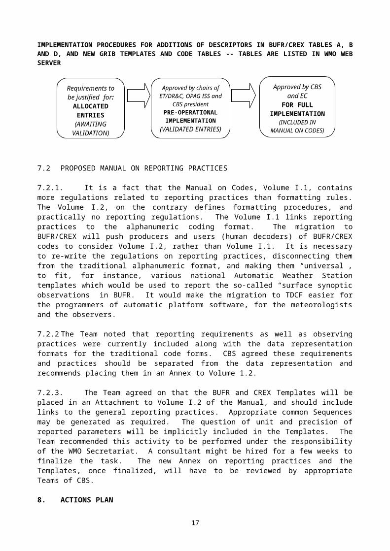
IMPLEMENTATION PROCEDURES FOR ADDITIONS OF DESCRIPTORS IN BUFR/CREX TABLES A, B AND D, AND NEW GRIB TEMPLATES AND CODE TABLES -- TABLES ARE LISTED IN WMO WEB SERVER
7.2 PROPOSED MANUAL ON REPORTING PRACTICES
7.2.1. It is a fact that the Manual on Codes, Volume I.1, contains more regulations related to reporting practices than formatting rules. The Volume I.2, on the contrary defines formatting procedures, and practically no reporting regulations. The Volume I.1 links reporting practices to the alphanumeric coding format. The migration to BUFR/CREX will push producers and users (human decoders) of BUFR/CREX codes to consider Volume I.2, rather than Volume I.1. It is necessary to re-write the regulations on reporting practices, disconnecting them from the traditional alphanumeric format, and making them “universal”, to fit, for instance, various national Automatic Weather Station templates which would be used to report the so-called “surface synoptic observations” in BUFR. It would make the migration to TDCF easier for the programmers of automatic platform software, for the meteorologists and the observers.
7.2.2 The Team noted that reporting requirements as well as observing practices were currently included along with the data representation formats for the traditional code forms. CBS agreed these requirements and practices should be separated from the data representation and recommends placing them in an Annex to Volume 1.2.
7.2.3. The Team agreed on that the BUFR and CREX Templates will be placed in an Attachment to Volume I.2 of the Manual, and should include links to the general reporting practices. Appropriate common Sequences may be generated as required. The question of unit and precision of reported parameters will be implicitly included in the Templates. The Team recommended this activity to be performed under the responsibility of the WMO Secretariat. A consultant might be hired for a few weeks to finalize the task. The new Annex on reporting practices and the Templates, once finalized, will have to be reviewed by appropriate Teams of CBS.
8. ACTIONS PLAN
8.1 NEXT MEETING:It was suggested to have the next meeting in a place situated in RA II or RA V to be able organize a follow-up training event in the same manner as it was done in Arusha.
8.2 TASKS: ECMWF and NCEP with possible help of NWS/MDL to validate PDTs 4.10 and 4.14 (2.1.2) Some Centres to validate GDTs 3.1000/1100/1200 and PDTs 4.1000/1001/1100/1101, and
check users feed-back (2.2). Some Centres to validate and experimentally test JPEG DRT 5.40000 and DT 7.40000 and
PNG DRT 5.40010 and DT 7.40010 (2.3.5). Centres to validate ENVISAT templates (3.1.1) NCEP and Australian Weather Bureau to validate SIGMET in BUFR Centres to validate oceanographic additions (3.4.1)
12
Requirements to be justified for:ALLOCATED
ENTRIES(AWAITING
VALIDATION)
Approved by chairs of ET/DR&C, OPAG ISS
and CBS presidentPRE-OPERATIONALIMPLEMENTATION
(VALIDATED ENTRIES)
Approved by CBS and EC
FOR FULL IMPLEMENTATION
(INCLUDED IN MANUAL ON
CODES)
Secretariat, assisted by member(s) of the Team, to define an exhaustive list of known data sub-categories (3.5.3)
Members to study necessity of date significance for a new edition of BUFR (3.5.4) Proposal for a new Satellite Master Table by Simon Elliott (EUMETSAT) (3.5.5) Team to debate on content of new edition and its impact on migration (3.6) Members test buoy data from service ARGOS in BUFR (3.7.1) Document by ICAO at next meeting on Amendment 73 (4.1) Organisation of XML Workshop by Secretariat (6.2) Secretariat to create merged Word file with all new descriptor entries and a file for computer
processing with the help of a data processing centre (7.1.1) Finalize reporting practices and common sequences - Secretariat and consultant (7.2.3) Validation of BUFR templates for traditional observations including TEMP, PILOT, SYNOP,
CLIMAT and updating METAR and SPECI Templates.
9. CLOSURE OF THE MEETING
The Meeting was closed by the Chairman of the ET/DR&C at 14.00 on Friday 21 February 2003.
_______________
13
ANNEX TO PARAGRAPH 1.1.1
ET/DR&C, Arusha, 17-21 February 2003
List of Participants
Mr Jean CLOCHARD, Chair Météo-France42 Avenue Coriolis31057 TOULOUSE CEDEXFRANCETel: (33 5) 6107 8104Fax: (33 5) 6107 8109Email: [email protected]
Mr Charles SANDERSBureau of MeteorologyGPO Box 1289KMELBOURNE VIC 3001AUSTRALIATel: (613) 9669 4040Fax: (613) 9669 4023Email: [email protected]
Ms Eva CERVENACzech Hydrometeorological InstituteNa Šabatce 17143 06 PRAGUE - KOMORANYCZECH REPUBLICTel: +(420 2) 4403 2215Fax: +(420 2) 4403 2235Email: [email protected]
Mr Atsushi SHIMAZAKIJapan Meteorological Agency1-3-4 Otemachi Chiyoda-kuTOKYO 100JAPANTel: (813) 3218 3825Fax: (813) 3211 8404Email: [email protected]
Mr Scylla M. SILLAYOTanzania Meteorological AgencyP.O. Box 3056DAR ES SALAAMUNITED REPUBLIC OF TANZANIATel: (255) 22 2 110 282
2 110 231Fax: (22) 22 2 112 471Email: [email protected]
Mr John HENNESSYECMWFShinfield ParkREADING BERKSHIRE RG2 9AXUNITED KINGDOMTel: (44118) 9499400Fax: (44118) 9869450 Email: [email protected]
Dr Simon ELLIOTTEUMETSATAm Kavalleriesand 31D-64295 DARMSTADTGERMANYTel: +49 6151 807 385Fax: +49 6151 807 304Email: [email protected]
WMO SECRETARIATMr Joël MARTELLETWorld Meteorological Organization7 bis, avenue de la PaixCase postale No. 2300CH-1211 GENEVA 2SwitzerlandTel: +41 22 730 8313Fax: +41 22 730 8021E-mail: [email protected]
14
ANNEX TO 2.3.5
JPEG 2000
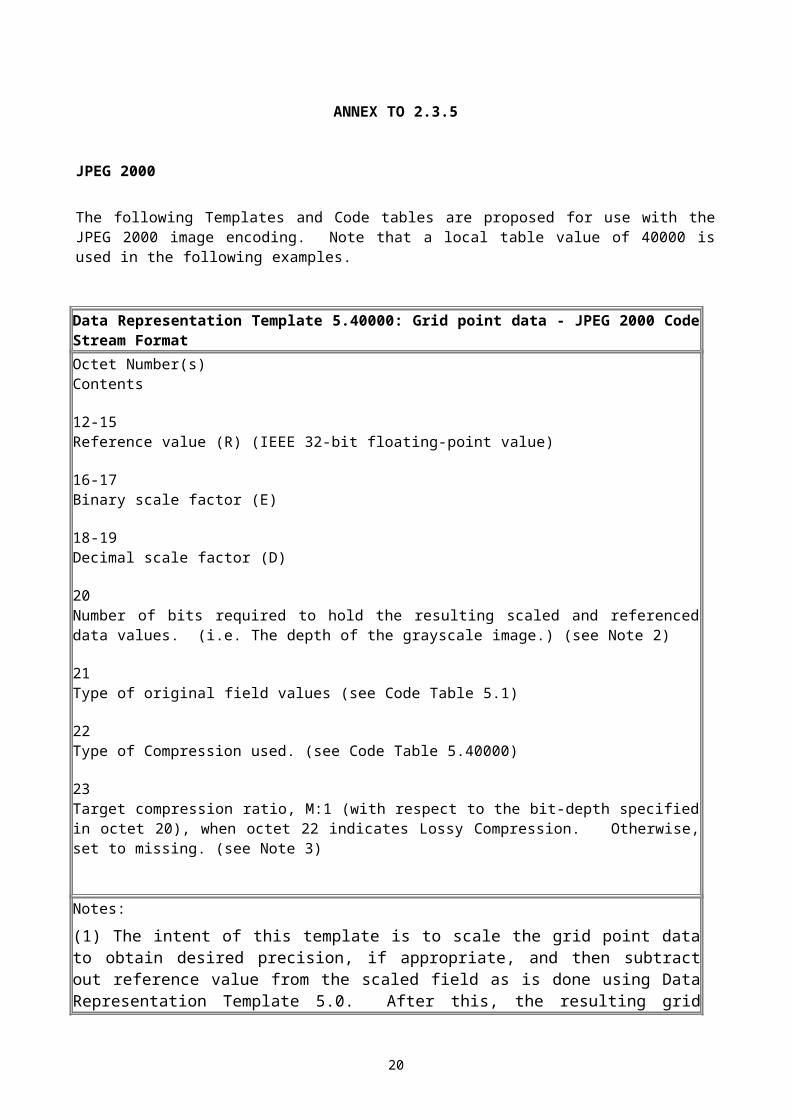
The following Templates and Code tables are proposed for use with the JPEG 2000 image encoding. Note that a local table value of 40000 is used in the following examples.
Data Representation Template 5.40000: Grid point data - JPEG 2000 Code Stream FormatOctet Number(s)Contents
12-15Reference value (R) (IEEE 32-bit floating-point value)
16-17Binary scale factor (E)
18-19Decimal scale factor (D)
20Number of bits required to hold the resulting scaled and referenced data values. (i.e. The depth of the grayscale image.) (see Note 2)
21Type of original field values (see Code Table 5.1)
22Type of Compression used. (see Code Table 5.40000)
23Target compression ratio, M:1 (with respect to the bit-depth specified in octet 20), when octet 22 indicates Lossy Compression. Otherwise, set to missing. (see Note 3)
Notes:
(1) The intent of this template is to scale the grid point data to obtain desired precision, if appropriate, and then subtract out reference value from the scaled field as is done using Data Representation Template 5.0. After this, the resulting grid point field can be treated as a grayscale image and is then encoded into the JPEG 2000 code stream format. To unpack the data field, the JPEG 2000 code stream is decoded back into an image, and the original field is obtained from the image data as described in regulation 92.9.4, Note (4).
(2) The JPEG 2000 standard specifies that the bit-depth must be in the range of 1 to 38 bits.
(3) The compression ratio M:1 ( e.g. 20:1 ) specifies that the encoded stream should be less than (1/M)*depth*number_of_data points bits, where depth is specified in octet 20 and number_of_data points is specified in octets 6-9 of the Data Representation Section.
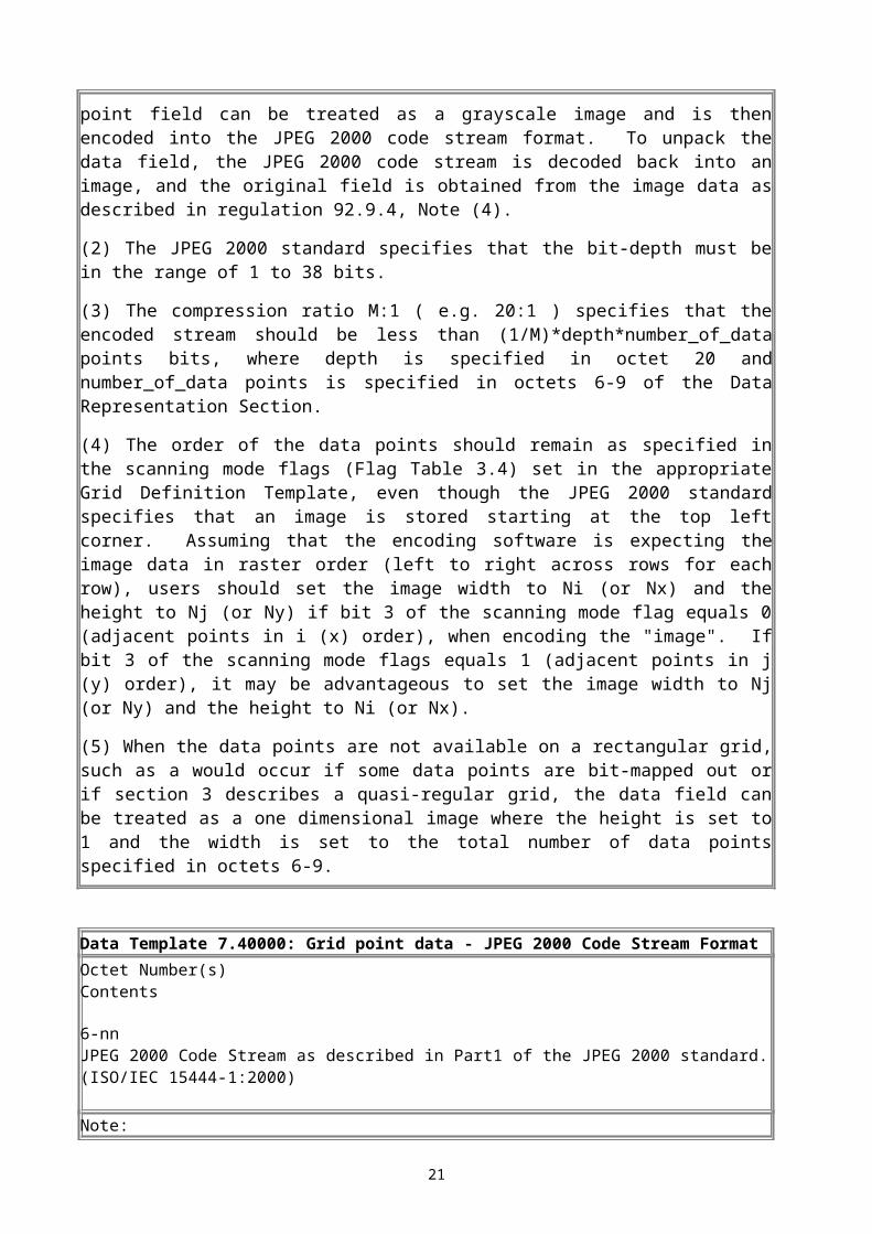
(4) The order of the data points should remain as specified in the scanning mode flags (Flag Table 3.4) set in the appropriate Grid Definition Template, even though the JPEG 2000 standard
15
specifies that an image is stored starting at the top left corner. Assuming that the encoding software is expecting the image data in raster order (left to right across rows for each row), users should set the image width to Ni (or Nx) and the height to Nj (or Ny) if bit 3 of the scanning mode flag equals 0 (adjacent points in i (x) order), when encoding the "image". If bit 3 of the scanning mode flags equals 1 (adjacent points in j (y) order), it may be advantageous to set the image width to Nj (or Ny) and the height to Ni (or Nx).
(5) When the data points are not available on a rectangular grid, such as a would occur if some data points are bit-mapped out or if section 3 describes a quasi-regular grid, the data field can be treated as a one dimensional image where the height is set to 1 and the width is set to the total number of data points specified in octets 6-9.
Data Template 7.40000: Grid point data - JPEG 2000 Code Stream FormatOctet Number(s)Contents
6-nnJPEG 2000 Code Stream as described in Part1 of the JPEG 2000 standard. (ISO/IEC 15444-1:2000)
Note:
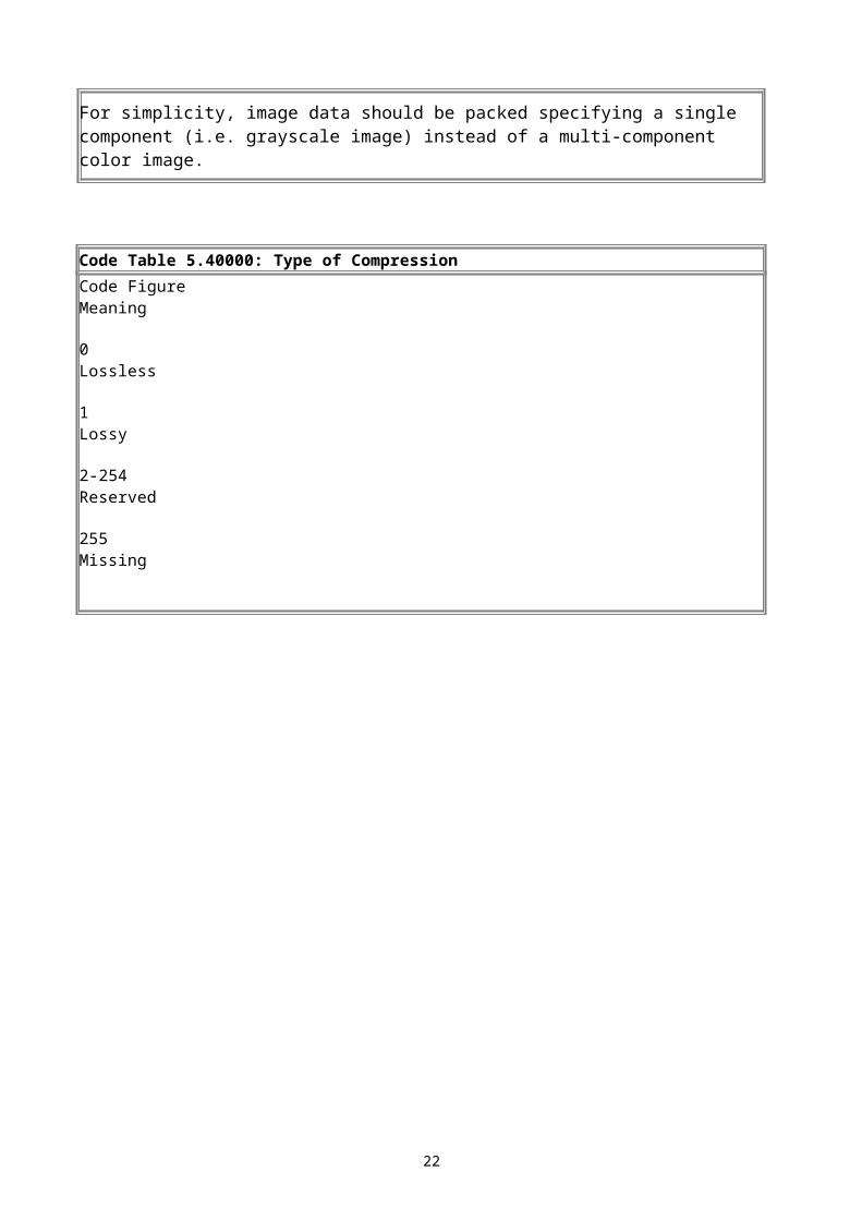
For simplicity, image data should be packed specifying a single component (i.e. grayscale image) instead of a multi-component color image.
Code Table 5.40000: Type of CompressionCode FigureMeaning
0Lossless
1Lossy
2-254Reserved
255Missing
16

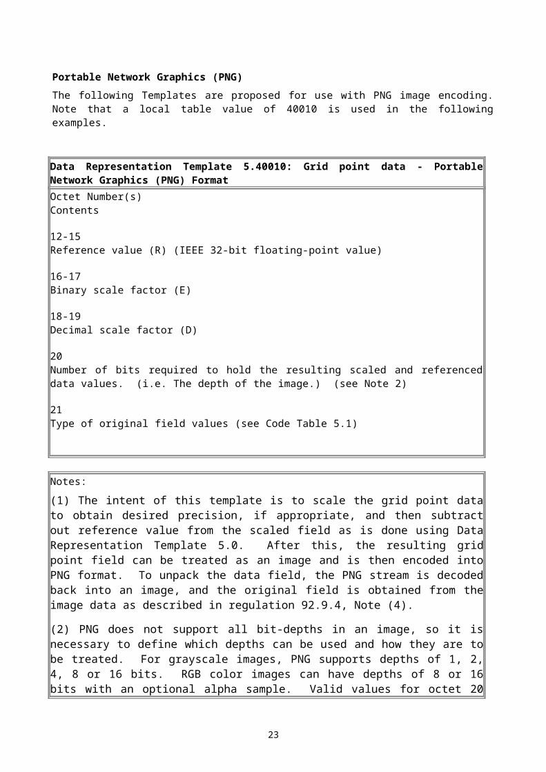
Portable Network Graphics (PNG)The following Templates are proposed for use with PNG image encoding. Note that a local table value of 40010 is used in the following examples.
Data Representation Template 5.40010: Grid point data - Portable Network Graphics (PNG) FormatOctet Number(s)Contents
12-15Reference value (R) (IEEE 32-bit floating-point value)
16-17Binary scale factor (E)
18-19Decimal scale factor (D)
20Number of bits required to hold the resulting scaled and referenced data values. (i.e. The depth of the image.) (see Note 2)
21Type of original field values (see Code Table 5.1)
Notes:
(1) The intent of this template is to scale the grid point data to obtain desired precision, if appropriate, and then subtract out reference value from the scaled field as is done using Data Representation Template 5.0. After this, the resulting grid point field can be treated as an image and is then encoded into PNG format. To unpack the data field, the PNG stream is decoded back into an image, and the original field is obtained from the image data as described in regulation 92.9.4, Note (4).
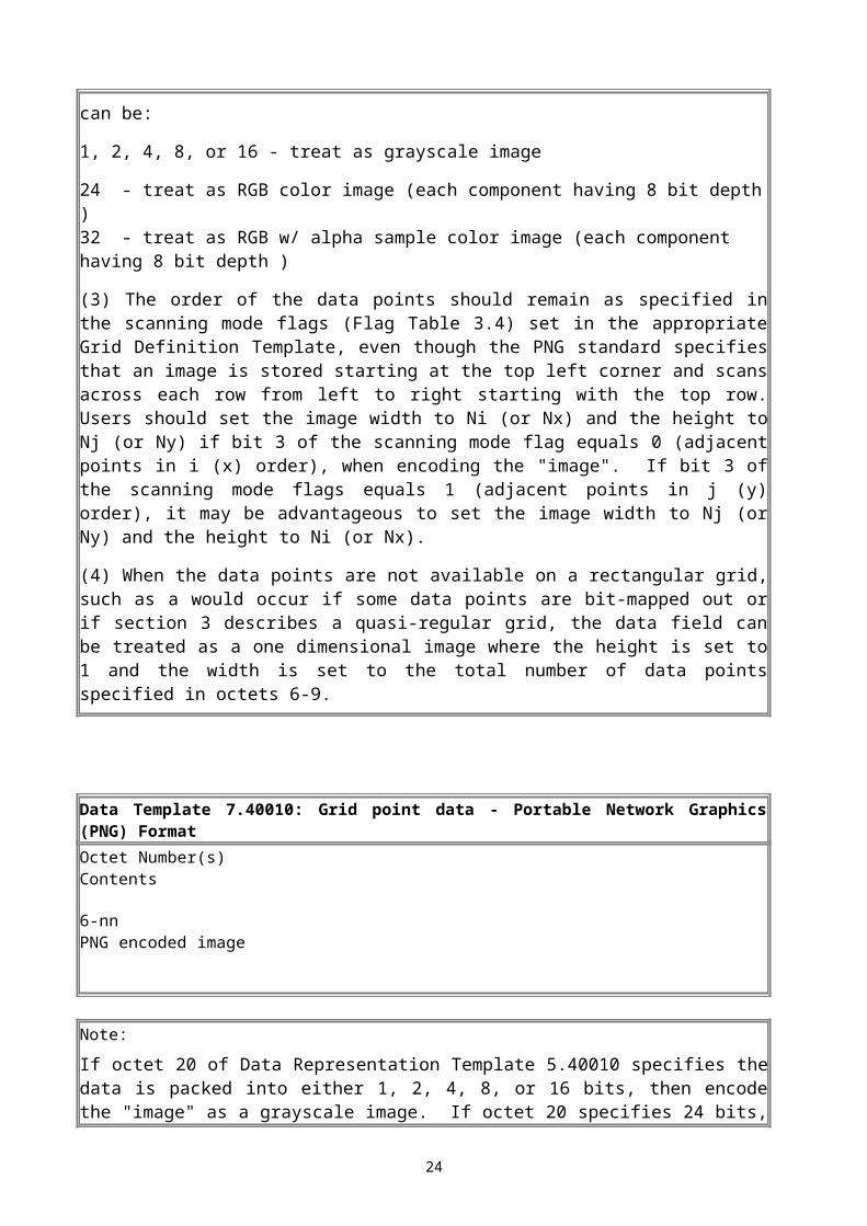
(2) PNG does not support all bit-depths in an image, so it is necessary to define which depths can be used and how they are to be treated. For grayscale images, PNG supports depths of 1, 2, 4, 8 or 16 bits. RGB color images can have depths of 8 or 16 bits with an optional alpha sample. Valid values for octet 20 can be:
1, 2, 4, 8, or 16 - treat as grayscale image
24 - treat as RGB color image (each component having 8 bit depth ) 32 - treat as RGB w/ alpha sample color image (each component having 8 bit depth )
(3) The order of the data points should remain as specified in the scanning mode flags (Flag Table 3.4) set in the appropriate Grid Definition Template, even though the PNG standard specifies that an image is stored starting at the top left corner and scans across each row from left to right starting with the top row. Users should set the image width to Ni (or Nx) and the height to Nj (or Ny) if bit 3 of the scanning mode flag equals 0 (adjacent points in i (x) order), when encoding the "image". If bit 3 of the scanning mode flags equals 1 (adjacent points in j (y)
17
order), it may be advantageous to set the image width to Nj (or Ny) and the height to Ni (or Nx).
(4) When the data points are not available on a rectangular grid, such as a would occur if some data points are bit-mapped out or if section 3 describes a quasi-regular grid, the data field can be treated as a one dimensional image where the height is set to 1 and the width is set to the total number of data points specified in octets 6-9.
Data Template 7.40010: Grid point data - Portable Network Graphics (PNG) FormatOctet Number(s)Contents
6-nnPNG encoded image
Note:
If octet 20 of Data Representation Template 5.40010 specifies the data is packed into either 1, 2, 4, 8, or 16 bits, then encode the "image" as a grayscale image. If octet 20 specifies 24 bits, encode the "image" as an RGB color image with 8 bit depth for each color component, and finally if octet 20 is 32, encode the "image" as a RGB color image with an alpha sample using an 8 bit depth for each of the four components.
18
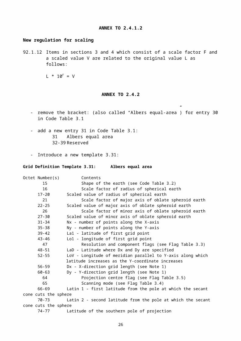
ANNEX TO 2.4.1.2
New regulation for scaling
92.1.12 Items in sections 3 and 4 which consist of a scale factor F and a scaled value V are related to the original value L as follows:
L * 10F = V
ANNEX TO 2.4.2
- remove the bracket: (also called “Albers equal-area”) for entry 30 in Code Table 3.1
- add a new entry 31 in Code Table 3.1:31 Albers equal area32-39 Reserved
- Introduce a new template 3.31:
Grid Definition Template 3.31: Albers equal area
Octet Number(s) Contents 15 Shape of the earth (see Code Table 3.2) 16 Scale factor of radius of spherical earth 17-20 Scaled value of radius of spherical earth 21 Scale factor of major axis of oblate spheroid earth 22-25 Scaled value of major axis of oblate spheroid earth 26 Scale factor of minor axis of oblate spheroid earth 27-30 Scaled value of minor axis of oblate spheroid earth 31-34 Nx - number of points along the X-axis 35-38 Ny - number of points along the Y-axis 39-42 La1 - latitude of first grid point 43-46 Lo1 - longitude of first grid point 47 Resolution and component flags (see Flag Table 3.3) 48-51 LaD - Latitude where Dx and Dy are specified 52-55 LoV - Longitude of meridian parallel to Y-axis along which latitude increases as the Y-
coordinate increases 56-59 Dx - X-direction grid length (see Note 1) 60-63 Dy - Y-direction grid length (see Note 1) 64 Projection centre flag (see Flag Table 3.5) 65 Scanning mode (see Flag Table 3.4) 66-69 Latin 1 - first latitude from the pole at which the secant cone cuts the sphere 70-73 Latin 2 - second latitude from the pole at which the secant cone cuts the sphere 74-77 Latitude of the southern pole of projection 78-81 Longitude of the southern pole of projection
Notes:(1) Grid lengths are in units of 10-3 m, at the latitude specified by LaD.(2) If Latin 1 = Latin 2, then the projection is on a tangent cone.(3) The resolution flags (bits 3-4 of Flag Table 3.3) are not applicable(4) LoV is the longitude value of the meridian which is parallel to the Y-axis (or columns of the grid) along
which latitude increases as the Y-coordinate increases (the orientation longitude may or may not appear on a particular grid).
19
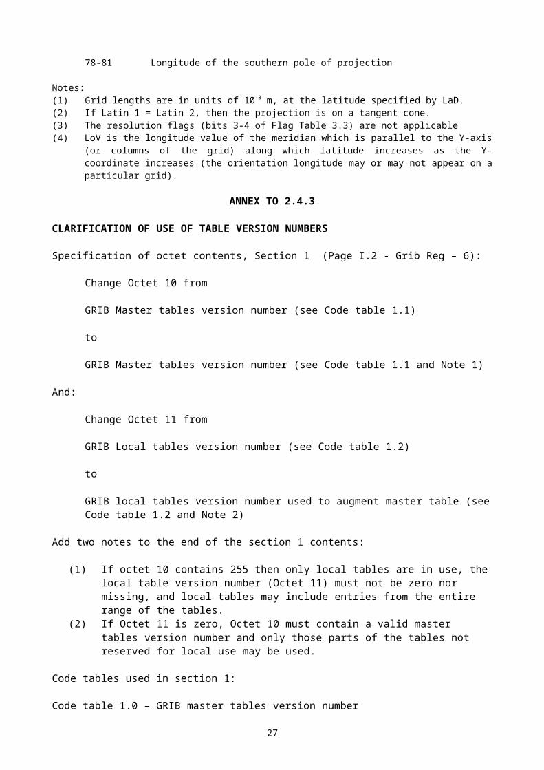
ANNEX TO 2.4.3
CLARIFICATION OF USE OF TABLE VERSION NUMBERS
Specification of octet contents, Section 1 (Page I.2 - Grib Reg – 6):
Change Octet 10 from
GRIB Master tables version number (see Code table 1.1)
to
GRIB Master tables version number (see Code table 1.1 and Note 1)
And:
Change Octet 11 from
GRIB Local tables version number (see Code table 1.2)
to
GRIB local tables version number used to augment master table (see Code table 1.2 and Note 2)
Add two notes to the end of the section 1 contents:
(1) If octet 10 contains 255 then only local tables are in use, the local table version number (Octet 11) must not be zero nor missing, and local tables may include entries from the entire range of the tables.
(2) If Octet 11 is zero, Octet 10 must contain a valid master tables version number and only those parts of the tables not reserved for local use may be used.
Code tables used in section 1:
Code table 1.0 – GRIB master tables version number
Change:
255 Local table usedto
255 Master tables not used. Local table entries and local templates may use the entire range of the table, not just those sections marked “Reserved for local use”.
20
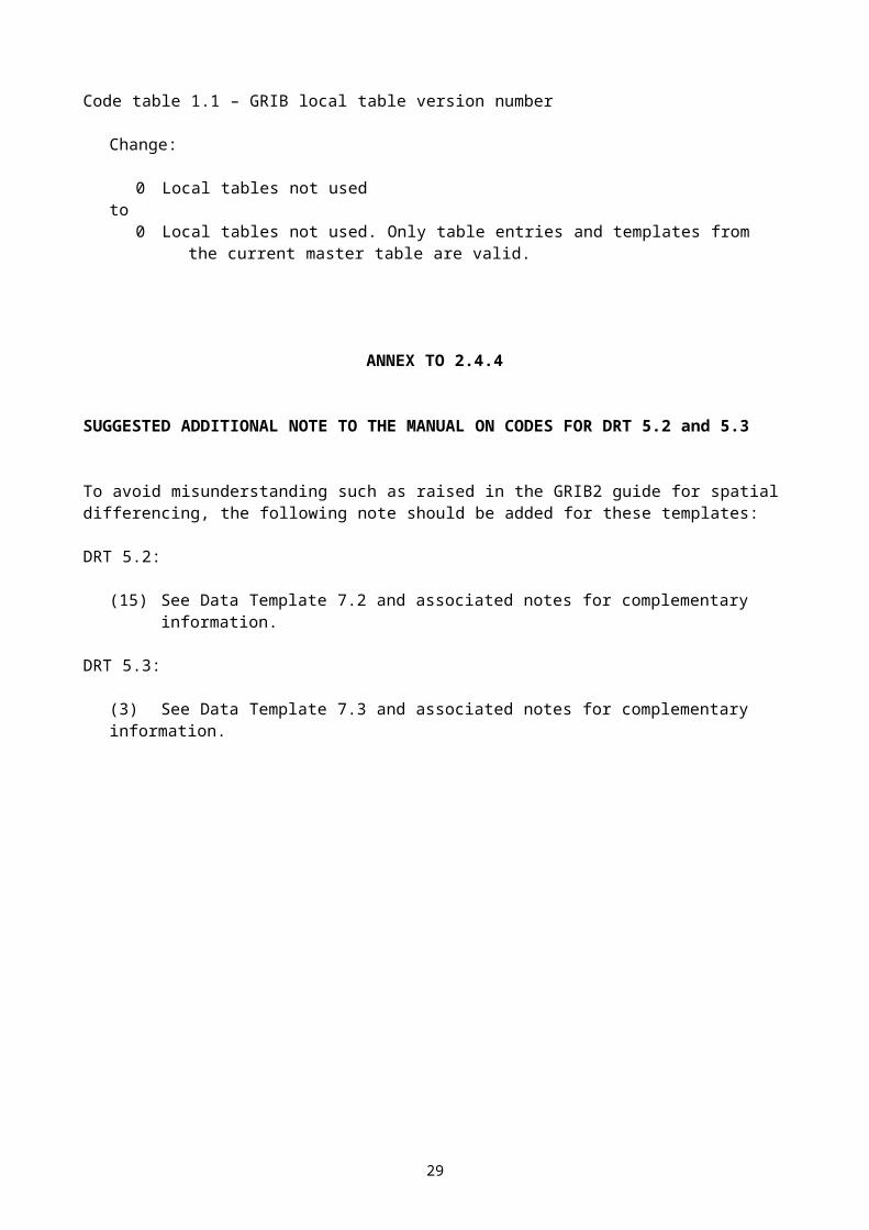
Code table 1.1 – GRIB local table version number
Change:
0 Local tables not usedto
0 Local tables not used. Only table entries and templates from the current master table are valid.
ANNEX TO 2.4.4
SUGGESTED ADDITIONAL NOTE TO THE MANUAL ON CODES FOR DRT 5.2 and 5.3
To avoid misunderstanding such as raised in the GRIB2 guide for spatial differencing, the following note should be added for these templates:
DRT 5.2:
(15) See Data Template 7.2 and associated notes for complementary information.
DRT 5.3:
(3) See Data Template 7.3 and associated notes for complementary information.
21
ANNEX TO 3.1.1
ADDITIONS FOR ENVISAT DATA
a) AATSR - Advanced Along Track Scanning Radiometer is the advanced version of the ATSR system operated on ERS1 and ERS2. The main objective of the AATSR is precise measurement of sea surface temperature (SST).
Proposal for standard WMO BUFR Table B entries:------------------------------------------------
025061 SOFTWARE IDENTIFICATION CCITTIA5 0 0 96 AND VERSION NUMBER001096 STATION ACQUISITION CCITTIA5 0 0 160002174 MEAN ACROSS TRACK PIXEL NUMERIC 0 0 9 NUMBER012180 AVERAGED 12 MICRON BT FOR K 2 0 16 ALL CLEAR PIXELS AT NADIR012181 AVERAGED 11 MICRON BT FOR K 2 0 16 ALL CLEAR PIXELS AT NADIR012182 AVERAGED 3.7 MICRON BT K 2 0 16 FOR ALL CLEAR PIXELS AT NADIR012183 AVERAGED 12 MICRON BT FOR K 2 0 16 ALL CLEAR PIXELS, FORWARD VIEW012184 AVERAGED 11 MICRON BT K 2 0 16 FOR ALL CLEAR PIXELS, FORWARD VIEW012185 AVERAGED 3.7 MICRON BT K 2 0 16 FOR ALL CLEAR PIXELS, FORWARD VIEW012186 MEAN NADIR SEA SURFACE K 2 0 16 TEMPERATURE012187 MEAN DUAL VIEW SEA K 2 0 16 SURFACE TEMPERATURE021086 NUMBER OF PIXELS IN NADIR NUMERIC 0 0 9 ONLY, AVERAGE021087 NUMBER OF PIXELS IN DUAL NUMERIC 0 0 9 VIEW, AVERAGE033043 AST CONFIDENCE FLAG TABLE 0 0 8
033043 FLAG TABLE AST CONFIDENCE
Bit No. Meaning
1 SEA MDS. NADIR ONLY SST RETRIEVAL USED 3.7 MICRON CHANNEL. LAND MDS RESERVED 2 SEA MDS. DUAL VIEW SST RETRIEVAL USED 3.7 MICRON CHANNEL. LAND MDS RESERVED 3 NADIR VIEW CONTAINS DAY TIME DATA 4 FORWARD VIEW CONTAINS DAY TIME DATA 5-7 RESERVED All MISSING VALUE
Common Code Table C-5: 001007 - satellite identifier Add 60 for ENVISAT
22
Proposal for standard WMO BUFR Table D entries: -----------------------------------------------
312045 - AATSR sea surface temperatures
312045 001007 Satellite identifier 002019 Satellite instruments 001096 Station acquisition 025061 Software identification and version number 005040 Orbit number 301011 Date 301013 Time 301021 Lat/long 007002 Height or altitude 012180 Average 12 micron BT for all clear pixels at nadir 012181 Average 11 micron BT for all clear pixels at nadir 012182 Average 3.7 micron BT for all clear pixels at nadir 012183 Average 12 micron BT for all clear pixels, forward
view 012184 Average 11 micron BT for all clear pixels, forward
view 012185 Average 3.7 micron BT for all clear pixels, forward
view 002174 Mean across track pixel number 021086 Number of pixels in nadir only, average 012186 Mean nadir sea surface temperature 021087 Number of pixels in dual view, average 012187 Mean dual view sea surface temperature 033043 ATS confidence
b) SCIAMACHY- The Scanning Imaging Absorbtion Spectrometer for Atmospheric Cartography. The instrument provides spectra measured from light transmitted, back scattered or reflected by trace gases in the atmosphere.
Use standard entry 310020
c) MIPAS - The Michelson Interferometer for Passive Atmospheric Sounding. The instrument measures atmospheric radiation emitted by trace gases in the infrared spectral range 4.14 to 14.6 micro meters.
BUFR Table B reserved entry:
013098 INTEGRATED WATER VAPOUR KG/M**2 8 0 30 DENSITY
BUFR table D reserved entry:
310030 310022 Satellite id, product type 301011 Date 301013 Time 301021 Lat/long 304034 Lat/long, solar elevation, number of layers 310029 Layer, ozone, height, temperature and water vapour
23
310029 110000 031001 Delayed replication 201138 Change data width 202130 Change scale 007004 Pressure 007004 Pressure 202000 Cancel operator 201000 Cancel operator 015020 Integrated ozone density 010002 Height 012101 Temperature 013098 Integrated water vapour density
d) GOMOS - The Global Ozone Monitoring by Occulation of Stars Gomos measures tangential atmospheric ultraviolet, visual and infrared light.
The BUFR template is the same as for MIPAS data
e) MERIS - The Medium Resolution Imaging Spectrometer: The instrument produces multi-spectral images obtained in a downward viewing push broom imaging manner. The 15 bands acquire radiance in the visible and near infra-red bands.
BUFR table B reserved entries:
010080 VIEWING ZENITH ANGLE DEGREE 2 -9000 15027080 VIEWING AZIMUTH ANGLE DEGREE TRUE 2 0 16013093 CLOUD OPTICAL THICKNESS NUMERIC 0 0 8013095 TOTAL COLUMN WATER VAPOUR KG/M**2 4 0 19
BUFR table D reserved entries:
312050 001007 Satellite identifier 002019 Instrument type 001096 Station acquisition 025061 Software identification 005040 Orbit number 301011 Date 301013 Time 301021 Lat/long 007025 Solar zenith angle 005022 Solar azimuth 010080 Viewing zenith angle 027080 Viewing azimuth angle 008003 Vertical significance 007004 Pressure 013093 Cloud optical thickness 008003 Vertical significance 201131 Change data width 202129 Change scale 007004 Pressure
24
007004 Pressure 202000 Cancel operator 201000 Cancel operator 013095 Total column water vapour
25
f) ASAR - The Advanced Synthetic Aperture Radar is a high resolution imaging radar.
Ocean cross spectra - ( WVS )
312051 001007 Satellite identifier 002019 Satellite instrument type 001096 Station acquisition 025061 Software identification 005040 Orbit number 008075 Ascending/descending orbit qualifier 301011 Date 301013 Time 301021 Lat/long 001012 Direction of motion of moving observing platform 201131 Change data width 001013 Speed of motion of moving observing platform 201000 Cancel operator 010032 Satellite distance to Earth centre 010033 Altitude (platform to ellipsoid) 010034 Earth radius 007002 Height 008012 Land/sea qualifier 025110 Image processing summary 025111 Number of input data gaps 025102 Number of missing lines excluding data gaps 002104 Antenna polarisation 025103 Number of directional bins 025104 Number of wave-length bins 025105 First directional bin 025106 Directional bin step 025107 First wave-length bin 025108 Last wave-length bin 002111 Radar incidence angle 002121 Mean frequency 002026 Cross track resolution 002027 Along track resolution 021130 Spectrum total energy 021131 Spectrum maximum energy 021132 Direction of spectrum max on higher resolution grid 021133 Wavelength of spectrum max on higher resolution grid 021064 Clutter noise estimate 025014 Azimuth clutter cut-off 021134 Range resolution of cross covariance spectrum 107018 Replicate next 7 descriptors 18 times 005030 Direction (spectral) 105024 Replicate 5 descriptors 24 time 201130 Change data width 006030 Wave number (spectral) 201000 Cancel operator 021135 Real part of cross spectra 021136 Imaginary part of cross spectra 033044 ASAR quality
New Table B descriptors
010032 SATELLITE DISTANCE TO EARTH M 1 0 27 CENTRE 010033 ALTITUDE (PLATFORM TO ELLIPSOID) M 1 0 27010034 EARTH RADIUS M 1 0 27025110 IMAGE PROCESSING SUMMARY FLAG TABLE 0 0 10
26

025111 NUMBER OF INPUT DATA GAPS NUMERIC 0 0 8025102 NUMBER OF MISSING LINES EXCLUDING NUME 0 0 8 DATA GAPS 025103 NUMBER OF DIRECTIONAL BINS NUMERIC 0 0 8025104 NUMBER OF WAVE-LENGHT BINS NUMERIC 0 0 8025105 FIRST DIRECTIONAL BIN DEGREES 3 0 19025106 DIRECTIONAL BIN STEP DEGREES 3 0 19025107 FIRST WAVE-LENGHT BIN M 3 0 29025108 LAST WAVE-LENGHT BIN M 3 0 29021130 SPECTRUM TOTAL ENERGY NUMERIC 6 0 28021131 SPECTRUM MAX ENERGY NUMERIC 6 0 28021132 DIRECTION OF SPECTRUM MAX ON DEGREES 3 0 19 HIGHER RESOLUTION GRID 021133 WAVE-LENGHT OF SPECTRUM MAX ON M 3 0 29 HIGHER RESOLUTION GRID 021134 RANGE RESOLUTION OF CRESS RAD/M 3 0 19 COVARIANCE SPECTRUM 021135 REAL PART OF CROSS SPECTRA NUMERIC 3 -524288 20 POLAR GRID NUMBER OF BINS 021136 IMAGINARY PART OF CROSS SPECTRA NUMERIC 3 -524288 20 POLAR GRID NUMBER OF BINS 033044 ASAR QUALITY INFORMATION FLAG TABLE 0 0 15
Flag table 025100 IMAGE PROCESSING SUMMARY
bit number Meaning
1 Raw data analysis used for raw data correction. Correction done using default parameters 2 Raw data analysis used for raw data correction. Correction done using raw data analysis results 3 Antenna elevation pattern correction applied 4 Nominal chirp replica used 5 Reconstructed chirp used 6 Slant range to ground range Conversion applied 7-9 Reserved All 10 Missing value
Flag table 033044 ASAR QUALITY INFORMATION
bit number Meaning
1 Input data mean outside nominal range flag 2 Input data standard deviation outside nominal range flag 3 Number of input data gaps > threshold value 4 Percentage of missing lines > threshold value 5 Doppler centroid uncertain. Confidence measure < specific
value 6 Doppler ambiguity estimate uncertain. Confidence measure <
specific value 7 Output data mean outside nominal range flag 8 Output data standard deviation outside nominal range flag 9 Chirp reconstruction failed or is of low quality flag 10 Data set missing 11 Invalid downlink parameters 12 Azimuth cut-off iteration count. The azimuth cut- off fit did
not converge within minimum number of iterations 13 Azimuth cut-off fit did not converge within a minimum number
of iterations
27
14 Phase information confidence measure. The imaginary spectral peak is less than
a minimum threshold, or the zero lag shift is greater than a minimum threshold
All 15 Missing value
28
OCEAN WAVE SPECTRA--------------------
Table D sequence
312053 001007 Satellite identifier 002019 Satellite instrument type 001096 Station acquisition 025061 Software identification and version number 005040 Orbit number 008075 Ascending/descending orbit qualifier 301011 Date 301013 Time 301021 Lat/long 001012 Direction of motion of moving observing platform 201131 Change data width 001013 Speed of motion of moving observing platform 201000 Cancel operator 010032 Satellite distance to Earth centre 010033 Altitude (platform to ellipsoid) 010034 Earth radius 007002 Height or altitude 008012 Land/sea qualifier 025110 Image processing summary 025111 Number of input data gaps 025102 Number of missing lines excluding data gaps 002104 Antenna polarisation 025103 Number of directional bins 025104 Number of wave-length bins 025105 First directional bin 025106 Directional bin step 025107 First wave-length bin 025108 Last wave-length bin 011001 Wind direction 011002 Wind speed 022160 Normalized inverse wave age 025138 Average signal to noise ratio 201130 Change data width 202129 Change scale 022021 Height of waves 202000 Cancel operator 201000 Cancel operator 033048 Confidence measure for SAR inversion 033049 Confidence measure for wind retrieval 002026 Cross track resolution 002027 Along track resolution 021130 Spectrum total energy 021131 Spectrum max energy 021132 Direction of spectrum max 021133 Wave-length of spectrum max 025014 Azimuth clutter cut-off 106036 Replicate 6 descriptors 36 times 005030 Direction (spectral) 104024 Replicate 4 descriptors 24 time 201130 Change data width 006030 Wave number (spectral) 201000 Cancel operator 022161 Wave spectra 033044 ASAR quality
29
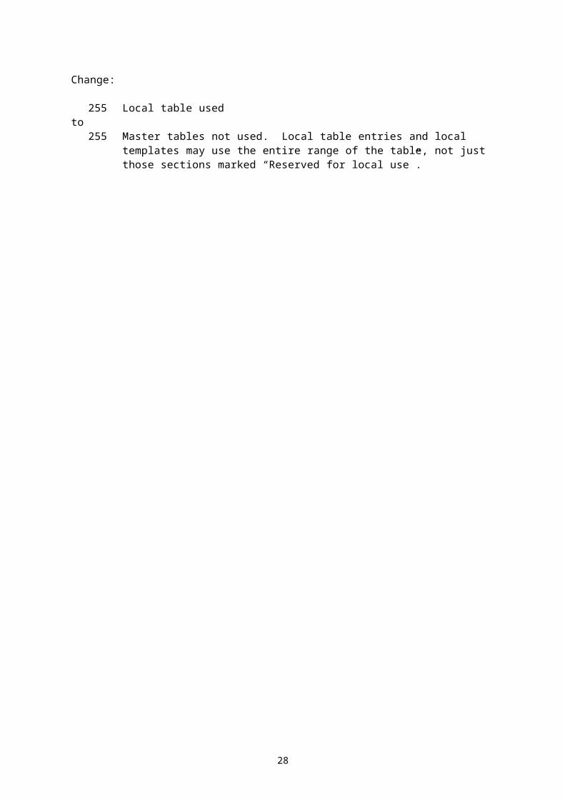
Table B descriptors
022160 NORMALIZED INVERSE WAVE AGE NUMERIC 6 0 21 025138 AVERAGE SIGNAL TO NOISE NUMERIC 0 -2048 12 RATIO 033048 CONFIDENCE MEASURE OF SAR CODE TABLE 0 0 2 INVERSION 033049 CONFIDENCE MEASURE OF WIND CODE TABLE 0 0 2 RETRIEVAL 022161 WAVE SPECTRA M**4 4 0 27
Code table 033048 CONFIDENCE MEASURE OF SAR INVERSION
code figure Meaning
0 inversion successful 1 inversion not successful 2 reserved 3 Missing
Code table 033049 CONFIDENCE MEASURE OF WIND RETRIEVAL
code figure Meaning
0 external wind direction used during inversion 1 External wind direction not used during inversion 2 reserved 3 Missing
g) RA2 - Radar Altimeter-2 -----------------------
312052 001007 Satellite identifier 002019 Satellite instrument type 001096 Station acquisition 025061 Software identification 005040 Orbit number 025120 Ra2 L2 processing flag 025121 Ra2 L2 processing quality 025124 MWR L2 processing flag 025125 MWR L2 processing quality 025122 Hardware configuration for RF 025123 Hardware configuration for HPA 301011 Date 301013 Time 301021 Lat/long 007002 Height or altitude 002115 Instrument operations 033047 Measurement confidence data 010081 Altitude of COG above reference ellipsoid 010082 Instantaneous altitude rate 010083 Off nadir angle of the satellite from platform data 010084 Off nadir angle of the satellite from waveform data 002116 Percentage of 320 MHz band processed 002117 Percentage of 80 MHz band processed 002118 Percentage of 20 MHz band processed 002156 Percentage of valid Ku ocean retracker measurements
30
002157 Percentage of valid S ocean retracker measurements 014055 Solar activity index 022150 Number of 18 Hz valid points for Ku band 022151 Ku band ocean range 022152 STD of 18Hz Ku band ocean range 022153 Number of 18 Hz valid points for S band 022154 S band ocean range 022155 STD of 18 Hz S band ocean range 022156 Ku band significant wave height 022157 STD of 18 Hz Ku band significant wave height 022158 S band significant wave height 022159 STD 18 Hz S band significant wave height 021137 Ku band corrected ocean backscatter coefficient 021138 STD Ku band corrected ocean backscatter coefficient 021139 Ku band net instrumental correction for AGC 021140 S band corrected ocean backscatter coefficient 021141 STD S band corrected ocean backscatter coefficient 021142 S band net instrumental correction for AGC 010085 Mean sea surface height 010086 Geoid height 010087 Ocean depth/land elevation 010088 Total geocentric ocean tide height solution 1 010089 Total geocentric ocean tide height solution 2 010090 Long period tide height 010091 Tidal loading height 010092 Solid earth tide height 010093 Geocentric pole tide height 011002 wind speed 025126 Model dry tropospheric correction 025127 Inverted barometer correction 025128 Model wet tropospheric correction 025129 MWR derived wet tropospheric correction 025130 Ra2 ionospheric correction on Ku band 025131 Ionospheric correction from Doris on Ku band 025132 Ionospheric correction from model on Ku band 025133 Sea state bias correction on Ku band 025134 Ra2 ionospheric correction on S band 025135 Ionospheric correction from Doris on S band 025136 Ionospheric correction from model on S band 025137 Sea state bias correction on S band 013096 MWR water vapour content 013097 MWR liquid water content 011085 u component of model wind vector 011086 v component of model wind vector 012188 Interpolated 23.8 GHz brightness temp from MWR 012189 Interpolated 36.5 GHz brightness temp from MWR 002158 RA- 2 instrument 002159 MWR instrument 033052 S band ocean retracking quality 033053 Ku band ocean retracking quality 021143 Ku band rain attenuation 021144 Altimeter rain flag
31
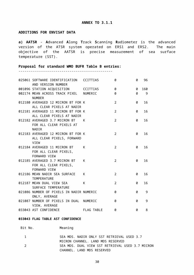
Table B descriptors
002119 RA - 2 INSTRUMENT OPERATIONS CODE TABLE 0 0 3002116 PERCENTAGE OF 320 MHZ BAND PROCESSED % 0 0 7002117 PERCENTAGE OF 80 MHZ BAND PROCESSED % 0 0 7002118 PERCENTAGE OF 20 MHZ BAND PROCESSED % 0 0 7002156 PERCENTAGE OF VALID KU OCEAN % 0 0 7 RETRACKER MEASUREMENTS 002157 PERCENTAGE OF VALID S OCEAN % 0 0 7 RETRACKER MEASUREMENTS 002158 RA - 2 INSTRUMENT FLAG TABLE 0 0 9002159 MWR INSTRUMENT FLAG TABLE 0 0 8010081 ALTITUDE OF COG ABOVE REFERENCE M 3 0 31 ELLIPSOID 010082 INSTANTANEOUS ALTITUDE RATE M/S 3 -65536 17010083 OFF NADIR ANGLE OF THE SATELLITE DEGREE 2 -36000 17 FROM PLATFORM DATA 010084 OFF NADIR ANGLE OF THE SATELLITE FROM WAVEFORM DATA DEGREE 2 -36000 17010085 MEAN SEA SURFACE HEIGHT M 3 -131072 18010086 GEOID HEIGHT M 3 -131072 18010087 OCEAN DEPTH/LAND ELEVATION M 1 -131072 18010088 TOTAL GEOCENTRIC OCEAN TIDE HEIGHT M 3 -32768 16 SOLUTION 1 010089 TOTAL GEOCENTRIC OCEAN TIDE HEIGHT M 3 -32768 16 SOLUTION 2 010090 LONG PERIOD TIDE HEIGHT M 3 -32768 16010091 TIDAL LOADING HEIGHT M 3 -32768 16010092 SOLID EARTH TIDE HEIGHT M 3 -32768 16010093 GEOCENTRIC POLE TIDE HEIGHT M 3 -32768 16011085 U COMPONENT OF THE MODEL WIND M/S 1 -4096 13 VECTOR 011086 V COMPONENT OF THE MODEL WIND M/S 1 -4096 13 VECTOR 012188 INTERPOLATED 23.8 GHZ BRIGHTNESS T K 2 0 16 FROM MWR 012189 INTERPOLATED 36.5 GHZ BRIGHTNESS T K 2 0 16 FROM MWR 013096 MWR WATER VAPOUR CONTENT KG/M**2 2 0 14013097 MWR LIQUID WATER CONTENT KG/M**2 2 0 14014055 SOLAR ACTIVITY INDEX NUMERIC 0 -32768 14021137 KU BAND CORRECTED OCEAN DB 2 -32768 16 BACKSCATTER COEFFICIENT 021138 STD KU BAND CORRECTED OCEAN DB 2 -32768 16 BACKSCATTER COEFFICIENT 021139 KU BAND NET INSTRUMENTAL DB 2 -2048 12 CORRECTION FOR ACG 021140 S BAND CORRECTED OCEAN DB 2 -32768 16 BACKSCATTER COEFFICIENT 021141 STD S BAND CORRECTED OCEAN DB 2 -32768 16 BACKSCATTER COEFFICIENT 021142 S BAND NET INSTRUMENTAL DB 2 -1024 11 CORRECTION FOR ACG 021143 KU BAND RAIN ATTENUATION DB 2 -1073741824 31021144 ALTIMETER RAIN FLAG FLAG TABLE 0 0 2022150 NUMBER OF 18 HZ VALID POINTS NUMERIC 0 0 10 FOR KU BAND 022151 KU BAND OCEAN RANGE M 3 0 31022152 STD OF 18 HZ KU BAND OCEAN RANGE M 3 0 16022153 NUMBER OF 18 HZ VALID POINTS FOR NUMERIC 0 0 10 S BAND 022154 S BAND OCEAN RANGE M 3 0 31
32

022155 STD OF 18 HZ S BAND OCEAN RANGE M 3 0 16022156 KU BAND SIGNIFICANT WAVE HEIGHT M 3 0 16022157 STD 18 HZ KU BAND SIGNIFICANT M 3 0 16 WAVE HEIGHT 022158 S BAND SIGNIFICANT WAVE HEIGHT M 3 0 16022159 STD 18 HZ S BAND SIGNIFICANT WAVE M 3 0 16 HEIGHT 025120 RA2_L2_PROCESSING FLAG CODE TABLE 0 0 2025121 RA2_L2_PROCESSING QUALITY % 0 0 7025122 HARDWARE CONFIGURATION FOR RF CODE TABLE 0 0 2025123 HARDWARE CONFIGURATION FOR HPA CODE TABLE 0 0 2025124 MWR L2 PROCESSING FLAG CODE TABLE 0 0 2025125 MWR L2 PROCESSING QUALITY % 0 0 7025126 MODEL DRY TROPOSPHERIC CORRECTION M 3 -32768 16025127 INVERTED BAROMETER CORRECTION M 3 -32768 16025128 MODEL WET TROPOSPHERIC CORRECTION M 3 -32768 16025129 MWR DERIVED WET TROPOSPHERIC M 3 -32768 16 CORRECTION 025130 RA2 IONOSPHERIC CORRECTION ON KU M 3 -32768 16 BAND 025131 IONOSPHERIC CORRECTION FROM DORIS M 3 -32768 16 ON KU BAND 025132 IONOSPHERIC CORRECTION FROM MODEL M 3 -32768 16 ON KU BAND 025133 SEA STATE BIAS CORRECTION ON M 3 -32768 16 KU BAND 025134 RA2 IONOSPHERIC CORRECTION ON S M 3 -32768 16 BAND 025135 IONOSPHERIC CORRECTION FROM DORIS M 3 -32768 16 ON S BAND 025136 IONOSPHERIC CORRECTION FROM MODEL M 3 -32768 16 ON S BAND 025137 SEA STATE BIAS CORRECTION ON S M 3 -32768 16 BAND 033052 S BAND OCEAN RETRACKING QUALITY FLAG TABLE 0 0 21033053 KU BAND OCEAN RETRACKING FLAG TABLE 0 0 21 QUALITY 033047 MEASUREMENT CONFIDENCE DATA FLAG TABLE 0 0 31
Code table 002180 INSTRUMENT OPERATIONS
Code figure Meaning
0 Intermediate Frequency Calibration Mode (IF CAL) 1 Built-In Test Equipment Digital (BITE DGT) 2 Built-In test Equipment Radio Frequency (BITE RF) 3 Preset tracking ( PSET TRK) 4 Preset LOOP OUT 5 ACQUISITION 6 TRACKING 7 MISSING VALUE
33
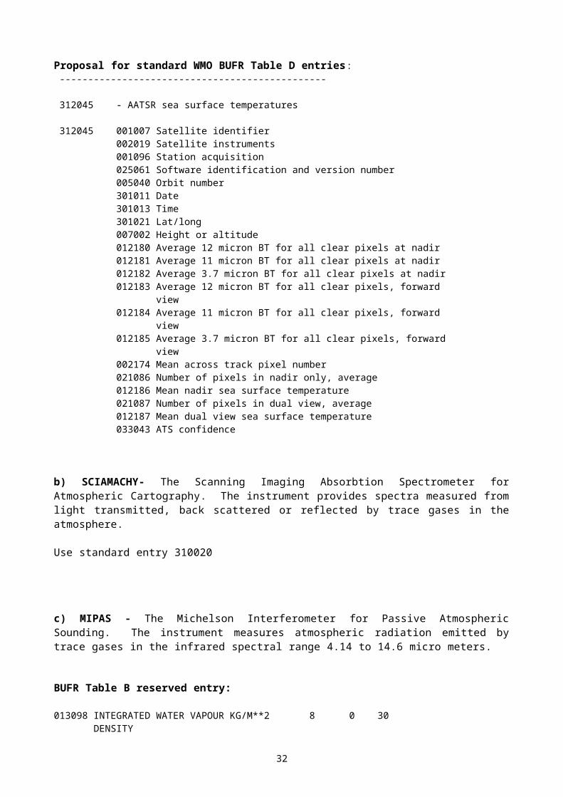
Flag table 002158 RA - 2 INSTRUMENT
bit number Meaning
1 MISMATCH IN RED VEC HPA 2 MISMATCH IN RED VEC RFSS 3 PTR CALIBRATION BAND 320 MHz (Ku) 4 PTR CALIBRATION BAND 80 MHz (Ku) 5 PTR CALIBRATION BAND 20 MHz (Ku) 6 PTR CALIBRATION BAND 160 MHz (S) 7 Ku FLIGHT CALIBRATION PARAMETERS AVAILABLE 8 S FLIGHT CALIBRATION PARAMETERS AVAILABLE All Missing value
PTR - Pulse target response HPA - High Power Amplifier RFSS - Radio Frequency Sub-System RED - Redundancy
Flag table 002159 MWR INSTRUMENT
bit number Meaning 1 Temperature inconsistency 2 Data is missing 3 Redundancy channel 4 Power bus protection 5 Overvoltage/Overload protection 6 Reserved 7 Reserved ALL Missing
MWR - Microwave radiometer
Flag table 021144 Altimeter rain flag
bit number Meaning
1 RAIN all Missing value
Code table 025120 RA2_l2_processing flag
code figure Meaning
0 Percentage of DSRs free of processing errors during Level 2 processing is greater than the acceptable threshold
1 Percentage of DSRs free of processing errors during Level 2 processing is less than the acceptable threshold
2 Reserved 3 Missing value
DSR - Data set record
34
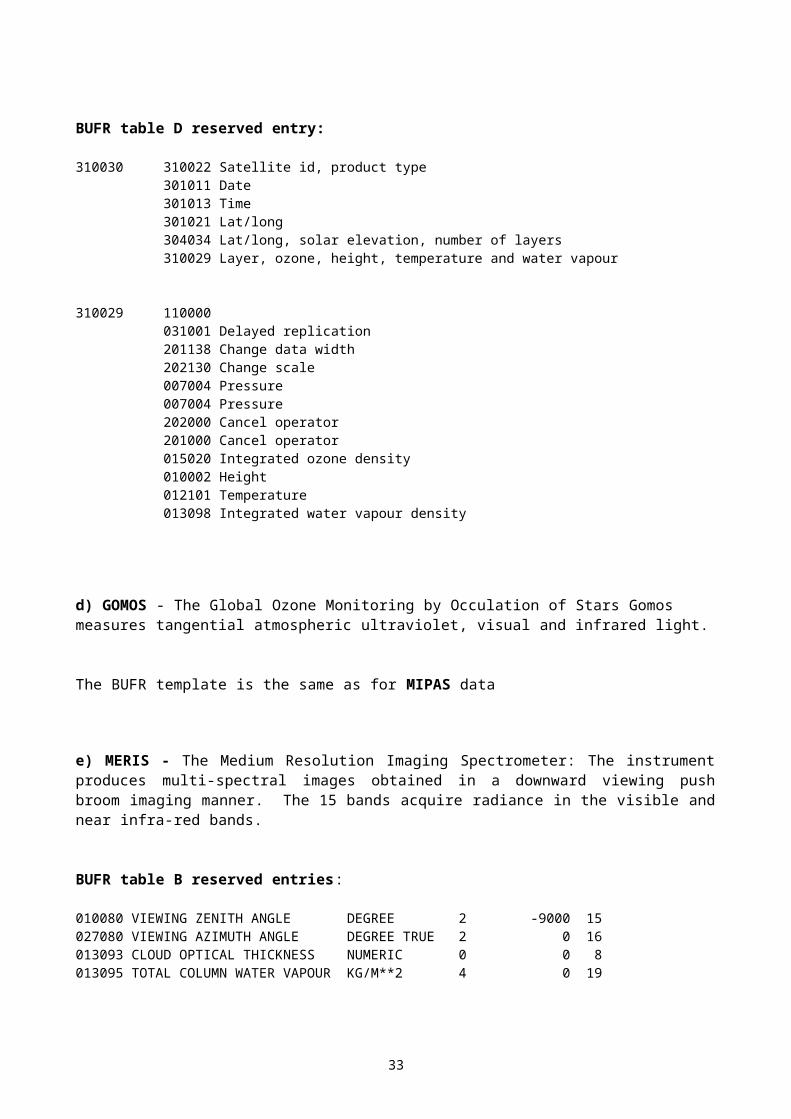
Code table 025122 Hardware configuration for RF Code figure Meaning
0 Hardware configuration for RF is A 1 Hardware configuration for RF is B 2 Reserved 3 Missing
RF - Radio frequency
Code table 025123 Hardware configuration for HPA
Code figure Meaning
0 Hardware configuration for HPA is A 1 Hardware configuration for HPA is B 2 Reserved 3 Missing
Code table 025124 MWR l2 processing flag
Code figure Meaning
0 Percentage of DSRs free of processing errors during Level 2 processing is greater than the acceptable threshold 1 Percentage of DSRs free of processing errors during Level 2 processing is less than the acceptable threshold 2 Reserved 3 Missing
DSR - Data Set Record MWR - Microwave radiometer
Flag table 033053 Ku band ocean retracking quality
bit number Meaning
1-20 First 20 least significant bits correspond to the 20 values (one per data block containing 0=valid measurement,
1=invalid) bit 1 applies to the 20th data block All Missing
Flag table 033052 S band ocean retracking quality
bit number Meaning
1-20 First 20 least significant bits correspond to the 20 values (one per data block containing 0=valid measurement,
1=invalid) bit 1 applies to the 20th data block All Missing
35
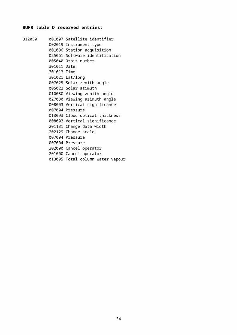
Flag table 033047 Measurement confidence data
bit number Meaning
1 Error detected and attempts to recover made 2 Anomaly in on-board data handling (OBDH) value detected 3 Anomaly in Ultra Stable Oscillator Processing (USOP) value
detected 4 Errors detected by on-board computer 5 Automatic gain control (AGC) out of range 6 Rx delay fault. Rx distance out of range 7 Wave form samples fault identifier. Error 8 Reserved 9 Reserved 10 Reserved 11 Reserved 12 Brightness temperature (channel 1) out of range 13 Brightness temperature (channel 2) out of range 14 Reserved 15 Ku Ocean retracking error 16 S Ocean retracking error 17 Ku Ice 1 retracking error 18 S Ice 1 retracking error 19 Ku Ice 2 retracking error 20 S Ice 2 retracking error 21 Ku Sea Ice retracking error 22 Arithmetic fault error 23 Meteo data state. No map 24 Meteo data state. 1 map 25 Meteo data state 2 maps degraded 26 Meteo data state 2 maps nominal 27 Orbit propagator status for propagation mode, several errors 28 Orbit propagator status for propagation mode, warning
detected 29 Orbit propagator status for initialisation mode, several
errors30 Orbit propagator status for initialisation mode, warning
detectedAll 31 Missing
36
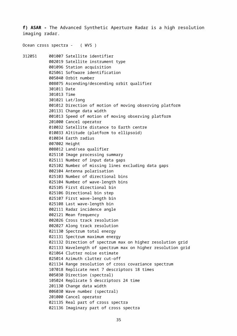
ANNEX TO 3.1.2.1
DESCRIPTORS FOR AIRS SATELLITE DATA for “PREOPERATIONAL STATUS”
In BUFR Table B:
Log-10 of principal components normalized fit to data0-25-052 Numeric 4 0 15
In BUFR Table D:
------------------------------------------------------------3-10-050 Satellite collocated 1C reports with 3 instruments------------------------------------------------------------
3-10-051 Satellite position and instrument temperatures3-10-052 Satellite instrument type and position (AIRS)1-01-000 Delayed replication of 1 descriptor0-31-002 Extended delayed descriptor replication factor3-10-053 Satellite channels and brightness temperatures with expanded
channel set (AIRS)1-01-004 Replicate 1 descriptor 4 times3-10-054 Satellite visible channels and albedos with expanded channel
set0-20-010 Cloud cover (total)3-10-052 Satellite instrument type and position (AMSU-A)1-01-015 Replicate 1 descriptor 15 times3-10-053 Satellite channels and brightness temperatures with expanded
channel set (AMSU-A)3-10-052 Satellite instrument type and position (HSB)1-01-005 Replicate 1 descriptor 5 times3-10-053 Satellite channels and brightness temperatures with expanded
channel set (HSB)
--------------------------------------------------------3-10-051 Satellite position and instrument temperatures--------------------------------------------------------
0-01-007 Satellite identifier0-05-040 Orbit number2-01-133 Change data width0-05-041 Scan line number2-01-000 Cancel change data width2-01-132 Change data width0-25-070 Major frame count2-01-000 Cancel change data width2-02-126 Change scale0-10-007 Height of station2-02-000 Cancel change scale0-07-025 Solar zenith angle0-05-022 Solar azimuth1-02-009 Replicate 2 descriptors 9 times0-02-151 Radiometer identifier0-12-064 Instrument temperature
37
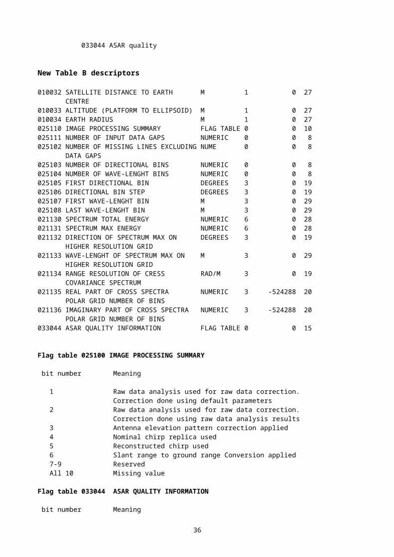
------------------------------------------------3-10-052 Satellite instrument type and position------------------------------------------------
0-02-019 Satellite instruments3-01-011 Year, month, day3-01-012 Hour, minute2-02-131 Change scale2-01-138 Change data width0-04-006 Second2-01-000 Cancel change data width2-02-000 Cancel change scale3-01-021 Latitude and longitude (high accuracy)0-07-024 Satellite zenith angle0-05-021 Bearing or azimuth0-05-043 Field of view number
------------------------------------------------------------------------------3-10-053 Satellite channels and brightness temperatures with expanded channel
set------------------------------------------------------------------------------
2-01-134 Change data width0-05-042 Channel number2-01-000 Cancel change data width0-25-076 Log-10 of temperature-radiance central wave number for ATOVS0-33-032 Channel quality flags for ATOVS0-12-163 Brightness temperature (scale 2)
--------------------------------------------------------------------------3-10-054 Satellite visible channels and albedos with expanded channel set--------------------------------------------------------------------------
2-01-134 Change data width0-05-042 Channel number2-01-000 Cancel change data width0-25-076 Log-10 of temperature-radiance central wave number for ATOVS0-33-032 Channel quality flags for ATOVS2-01-131 Change data width2-02-129 Change scale1-02-002 Replicate 2 descriptors 2 times0-08-023 First-order statistics0-14-027 Albedo0-08-023 First-order statistics2-02-000 Cancel change scale2-01-000 Cancel change data width
---------------------------------------------------------3-10-055 Satellite radiance/channel principle components---------------------------------------------------------
3-10-051 Satellite position and instrument temperatures3-10-052 Satellite instrument type and position (AIRS)1-02-020 Replicate 2 descriptors 20 times0-25-076 Log-10 of temperature-radiance central wave number for ATOVS0-25-052 Log-10 of principal components normalized fit to data1-01-000 Delayed replication of 1 descriptor0-31-002 Extended delayed descriptor replication factor
38
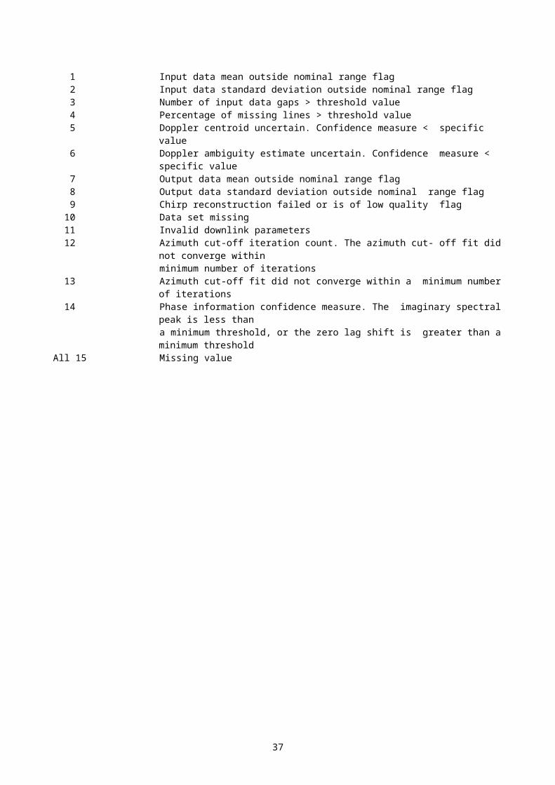
0-25-050 Principal components of satellite radiance
39
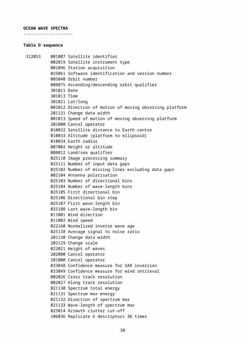
ANNEX TO 3.1.2.2
ADDITIONAL ENTRIES FOR SATELLITE DATA
For “PRE-OPERATIONAL” status:
(1) Within existing descriptor 0-02-163 “Height assignment method”, add the following new table entry:
0 AUTO EDITOR
(2) Within existing descriptor 0-01-007 “Satellite identifier”, add the following new table entries:
720 TOPEX721 GFO (GEOSAT Follow On)
(3) New table entry (was previously listed under “ALLOCATED ENTRIES (AWAITING VALIDATION)”, but has since been validated within processing of altimeter data):
Satellite cycle number0-05-044 Numeric 0 0 11B-05-044 Numeric 0 4
For “ALLOCATED ENTRIES (AWAITING VALIDATION)” status:
Satellite zenith angle0-07-026 Degrees 4 -900000 21B-07-026Degrees 4 7
40
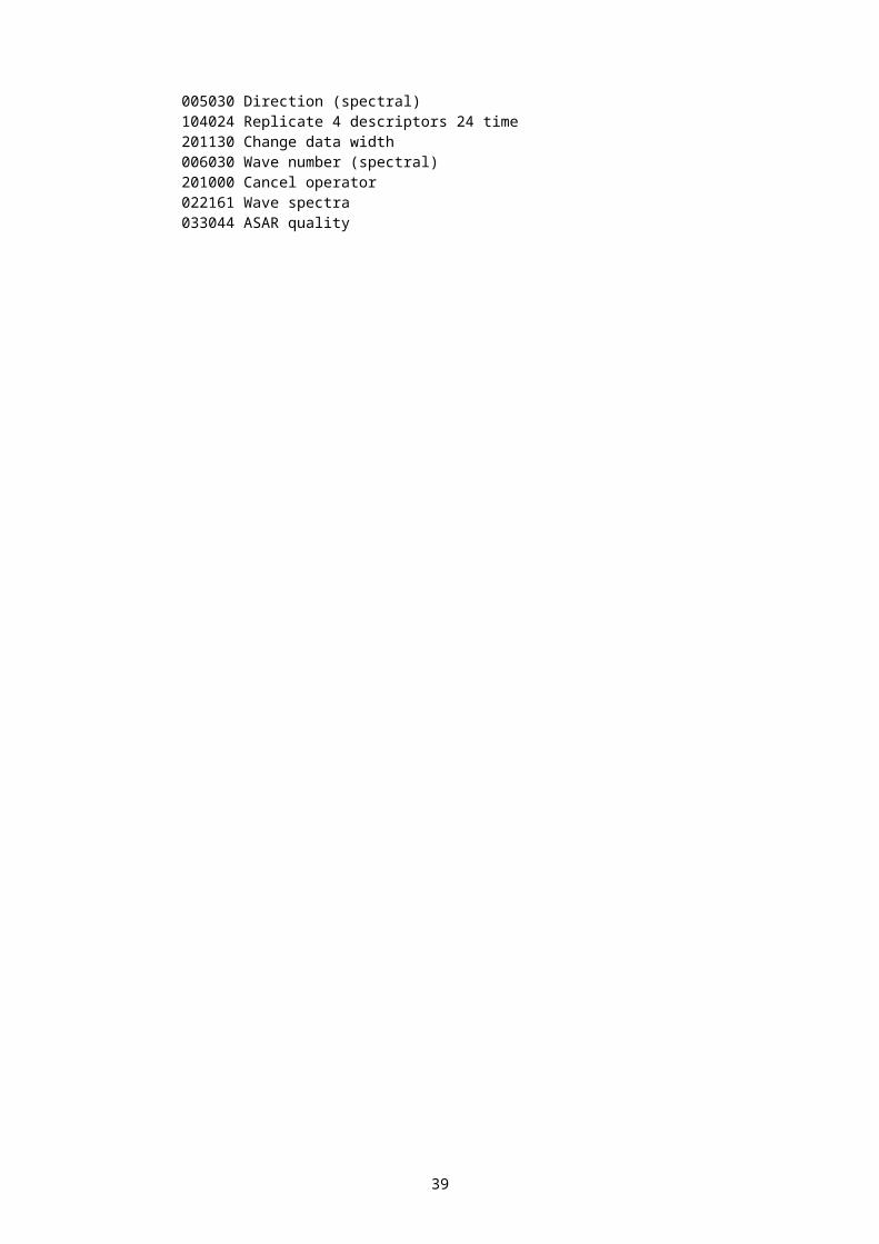
ANNEX TO 3.2.2
FOR CODING SIGMET WITH VOLUME ADDITIONS (I.E. ENHANCED PROPOSAL)
Proposed Table B entries
Table Reference
Element name BUFR CREX
F X Y Unit Scale Ref. value
Data width
Unit Scale Data width
0 01 037 SIGMET sequence identifier
CCITT IA5 0 0 24 Character 0 3
0 01 065 ICAO region identifier
CCITT IA5 0 0 256 Character 0 32
0 08 019 Qualifier for following centre identifier
Code table 0 0 4 Code table
0 2
0 08 079 Change in status of following product
Code table 0 0 3 Code table
0 1
0 10 064 SIGMET cruising level
Code table 0 0 3 Code table
0 1
0 20 028 Expected change in intensity
Code table 0 0 3 Code table
0 1
0 27 035 Length of phenomenon
m -3 0 13 m -3 4
0 28 035 Width of phenomenon
m -3 0 13 m -3 4
Add the following new categories to Table A within BUFR and CREX:
13 Forecasts14 Warnings
Add the following new code table values for the descriptors to Table B within BUFR:
0 08 01121 Thunderstorm22 Tropical Cyclone23 Mountain Wave24 Duststorm25 Sandstorm
0 20 00815 Obscured (OBSC)16 Embedded (EMBD)
0 20 024 5 Severe
41
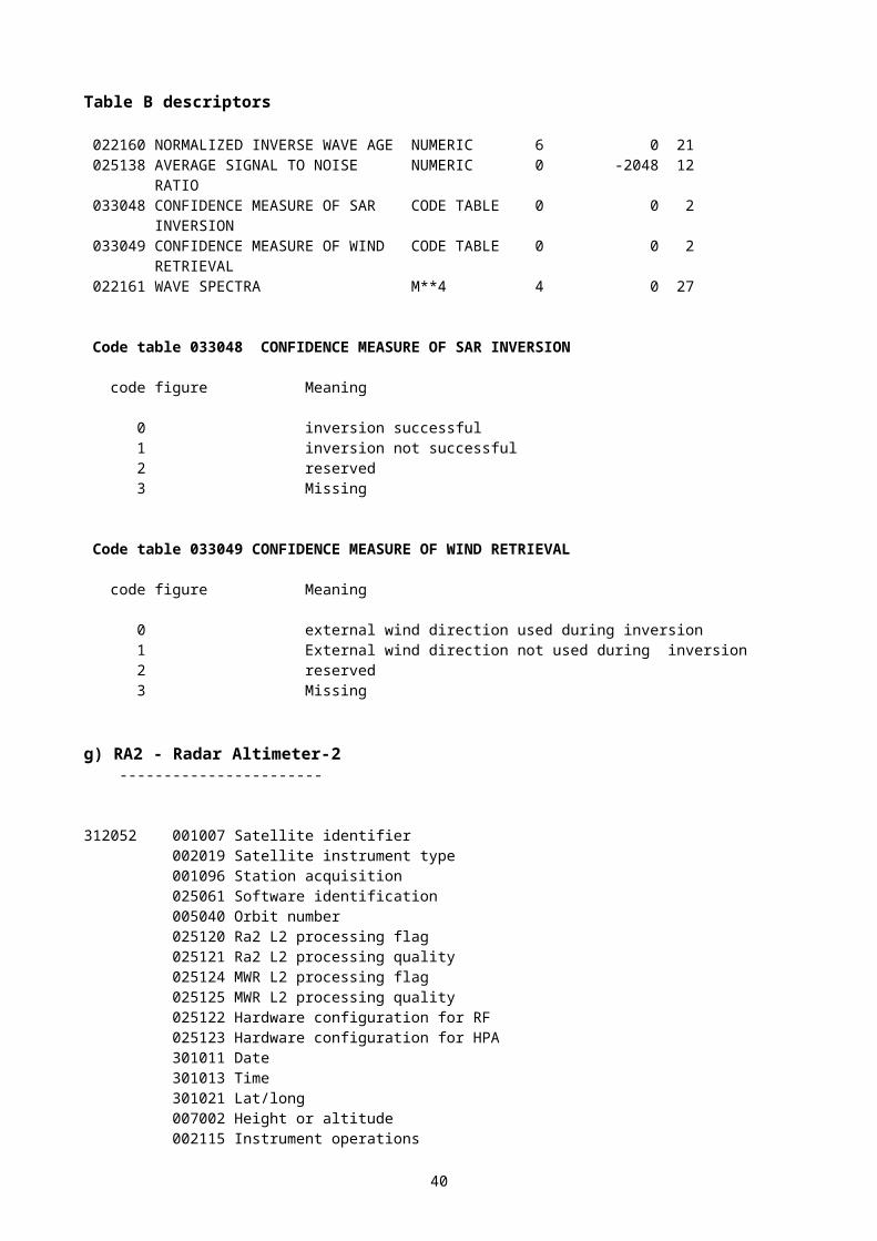
Code tables for proposed new Table B descriptors:
Code figure
0 08 019Qualifier for following centre identifier
0 Reserved1 ATS (Air Traffic Service) unit serving FIR (Flight Information Region)2 FIR (Flight Information Region)3 UIR (Upper Information Region)4 CTA (Control Area)5 VAAC (Volcanic Ash Advisory Centre)6 MWO (Meteorological Watch Office) issuing SIGMET7-14 Reserved15 Missing value
Code figure
0 08 079Change in status of following product
0 Cancelled1-6 Reserved7 Missing value
Code figure
0 10 064SIGMET cruising level
0 Subsonic1 Transonic2 Supersonic3-6 Reserved7 Missing value
Code figure
0 20 028Expected change in intensity
0 No change (NC)1 Forecast to weaken (WKN)2 Forecast to intensify (INTSF)3-6 Reserved7 Missing value
42
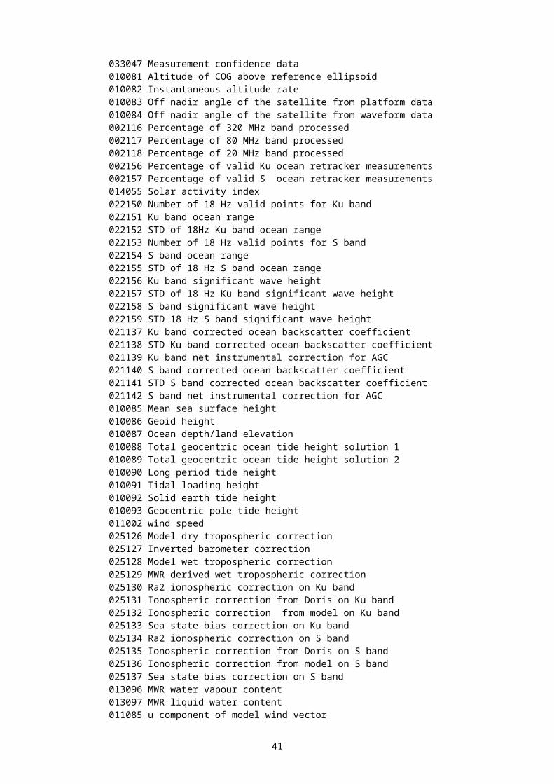
New Table D descriptors:
(Description of a feature in 3-D or in 2-D, in the last case replication = 1)
3 01 027 1 01 000 Replicate one descriptor0 31 001 Replication count3 01 028 Description of horizontal section 1
(Horizontal section of a feature described as a polygon or a line or a point; in the last case replication = 1)
3 01 028 0 07 010 Flight Level1 02 000 Replicate two descriptors 2
0 31 001 Replication count0 05 002 Latitude (coarse accuracy)0 06 002 Longitude (coarse accuracy)
(SIGMET header)3 16 030 1 02 002 Replication of 2 descriptors two times (Define validity period)
3 01 011 Year, Month, Day3 01 012 Hour, Minute0 01 037 SIGMET sequence identifier0 10 064 SIGMET cruising level0 08 019 Qualifier for location identifier, 1=ATS unit serving FIR0 01 062 Short ICAO location identifier1 02 000 Replicate two descriptors0 31 001 Replication count0 08 019 Qualifier for location identifier, 2=FIR, 3=UIR, 4=CTA0 01 065 ICAO region identifier0 08 019 Qualifier for location identifier, 6=MWO0 01 062 Short ICAO location identifier0 08 019 Qualifier for location identifier, Missing=Cancel
(SIGMET, Obs or Fcst location and motion)3 16 031 0 08 021 Time Significance, 16=Analysis, 4=Forecast
3 01 011 Year, Month, Day3 01 012 Hour, Minute0 07 010 Flight level (base)0 07 010 Flight level (top)0 27 035 Length of phenomenon0 28 035 Width of phenomenon0 08 007 Dimensional significance, 1=point, 2=area, 3=volume3 01 027 Description of feature0 19 005 Direction of motion0 19 006 Speed of motion0 19 007 Radius of feature0 08 007 Dimensional significance, Missing=cancel0 20 028 Expected change in intensity0 08 021 Time significance, Missing=cancel
1 3-D features should be described by a set of horizontal sections in successive ascending flight levels. 2 Polygon should be described by a sequence of contiguous points.
43
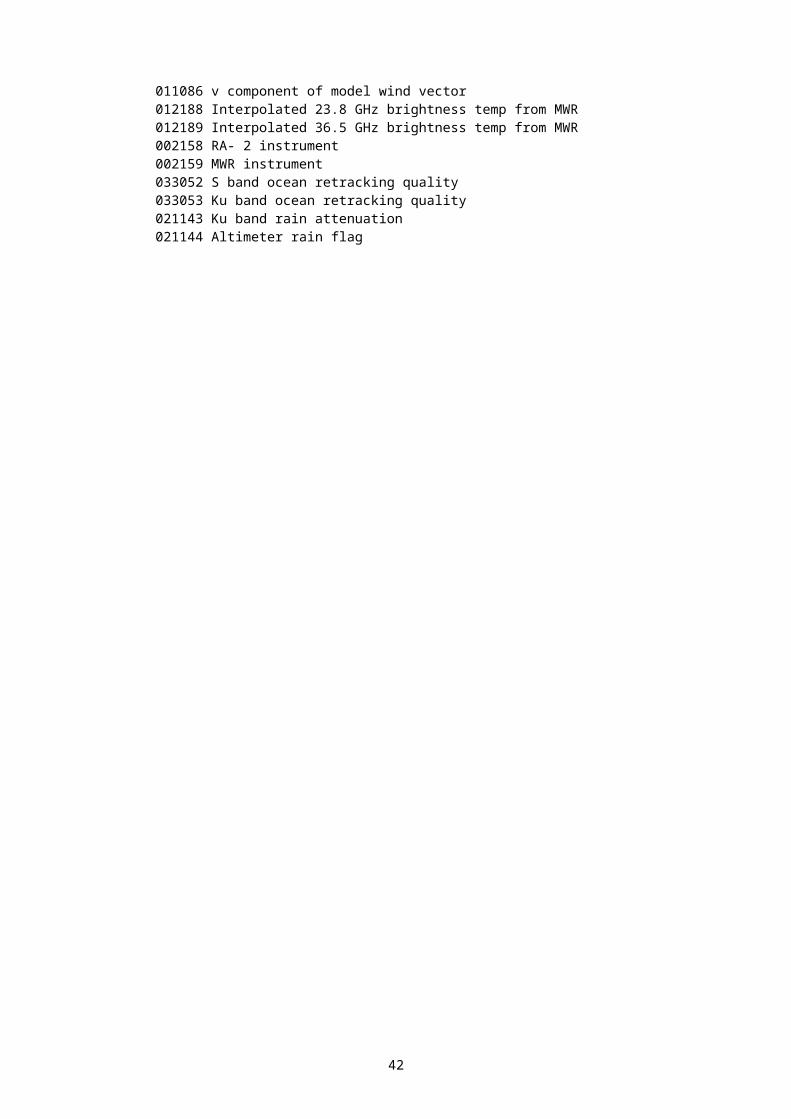
(SIGMET, Fcst position)3 16 032 0 08 021 Time Significance, 4=Forecast
3 01 011 Year, Month, Day3 01 012 Hour, Minute0 08 007 Dimensional significance, 1=point, 2=area1 01 000 Replicate one descriptor0 31 001 Replication count3 01 023 Latitude, longitude
0 08 007 Dimensional significance, Missing=cancel0 08 021 Time significance, Missing=cancel
(SIGMET, Outlook)3 16 033 0 08 021 Time Significance, 4=Forecast
3 01 011 Year, Month, Day3 01 012 Hour, Minute1 07 000 Replicate 7 descriptors0 31 001 Replication count0 07 010 Flight level (base)0 07 010 Flight level (top)0 08 007 Dimensional significance, 1=point, 2=area, 3=volume3 01 027 Description of feature0 08 007 Dimensional significance, Missing=cancel0 08 021 Time significance, Missing=cancel
(Volcanic Ash SIGMET)3 16 034 3 16 030 SIGMET Header
0 08 011 Meteorological feature, 17=Volcano0 01 022 Name of feature0 08 007 Dimensional significance, 0=Point3 01 023 Location0 08 007 Dimensional significance, Missing=Cancel0 20 090 Special Clouds, 5=Clouds from volcanic eruptions3 16 031 SIGMET Obs or Fcst location and motion1 01 000 Delayed replication0 31 000 Short replication factor3 16 032 SIGMET Fcst position1 01 000 Delayed replication0 31 001 Delayed replication factor3 16 033 SIGMET Outlook0 08 011 Meteorological feature, Missing=Cancel
(Thunderstorm SIGMET)3 16 035 3 16 030 SIGMET Header
0 08 011 Meteorological feature, 21=Thunderstorm0 20 023 Other weather phenomenon, bit 2=Squalls or all 18 bits = Missing0 20 021 Type of precipitation, bit 14=Hail or all 30 bits=Missing0 20 008 Cloud distribution 15=OBSC, 16=EMBD, 12=FRQ, 31=Missing3 16 031 SIGMET Obs or Fcst location and motion0 08 011 Meteorological feature, Missing=Cancel
44
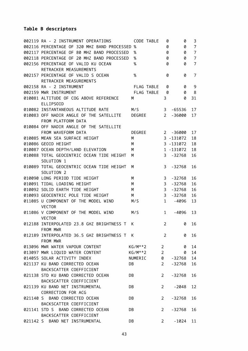
(Tropical Cyclone SIGMET)3 16 036 3 16 030 SIGMET Header
0 08 011 Meteorological feature, 22=Tropical Cyclone0 01 027 WMO storm name3 16 031 SIGMET Obs or Fcst location and motion1 01 000 Delayed replication0 31 000 Short replication factor3 16 032 SIGMET Fcst position1 01 000 Delayed replication0 31 001 Delayed replication factor3 16 033 SIGMET Outlook0 08 011 Meteorological feature, Missing=Cancel
(Turbulence SIGMET)3 16 037 3 16 030 SIGMET header
0 08 011 Meteorological feature, 13=Turbulence0 11 031 Degree of turbulence, 10=Mod, 11=Severe3 16 031 SIGMET Obs or Fcst location and motion0 08 011 Meteorological feature, Missing=Cancel
(Icing SIGMET)3 16 038 3 16 030 SIGMET header
0 08 011 Meteorological feature, 15=Airframe Icing0 20 041 Airframe icing, 7=Severe0 20 021 Type of precip, bit 3=Liquid freezing precip or all 30 bits = Missing3 16 031 SIGMET Obs or Fcst location and motion0 08 011 Meteorological feature, Missing=Cancel
(Mountain Wave SIGMET)3 16 039 3 16 030 SIGMET header
0 08 011 Meteorological feature, 23=Mountain Wave0 20 024 Intensity of phenomena, 5=Severe3 16 031 SIGMET Obs or Fcst location and motion0 08 011 Meteorological feature, Missing=Cancel
(Duststorm SIGMET)3 16 040 3 16 030 SIGMET header
0 08 011 Meteorological feature, 24=Duststorm0 20 024 Intensity of phenomena, 3=Heavy3 16 031 SIGMET Obs or Fcst location and motion0 08 011 Meteorological feature, Missing=Cancel
(Sandstorm SIGMET)3 16 041 3 16 030 SIGMET header
0 08 011 Meteorological feature, 25=Sandstorm0 20 024 Intensity of phenomena, 3=Heavy3 16 031 SIGMET Obs or Fcst location and motion0 08 011 Meteorological feature, Missing=Cancel
45
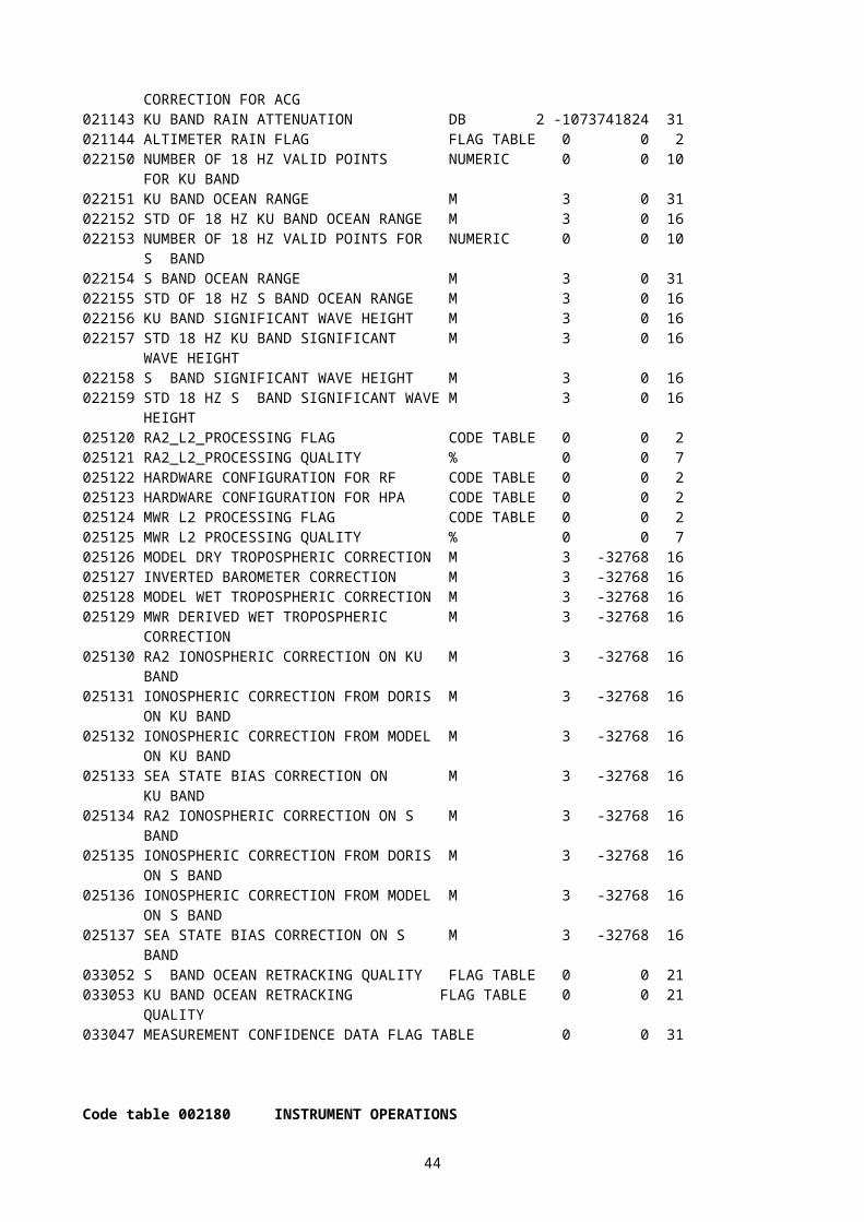
(Cancellation of SIGMET) 3 16 042 3 16 030 SIGMET header
0 08 079 Change in status of following product, 0 = Cancelled1 02 002 Replication of 2 descriptors two times (Define validity period)3 01 011 Year, Month, Day of the SIGMET to be cancelled3 01 012 Hour, Minute of the SIGMET to be cancelled0 01 037 SIGMET sequence identifier of the SIGMET to be cancelled0 10 064 SIGMET cruising level of the SIGMET to be cancelled 0 08 079 Change in status of following product, Missing = Cancel
46
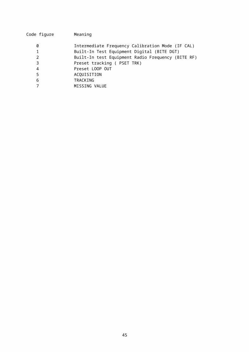
ANNEX TO 3.3
Common Code Table C-12: Sub-Centres of Originating Centres (entries in Tables C-1 and C-11)
ORIGINATING CENTRES SUB-CENTRESCode figure
Name Code figure
Name
C-1C-11
Octet 5, Section 1 of BUFROctet 26, Section 1 of GRIB
0 No Sub-CentreRegion IV00007 US NWS, NCEP 1 NCEP Reanalysis Project
2 NCEP Ensemble Products3 NCEP Central Operations4 Environmental Modeling Center5 Hydrometeorological Prediction
Center6 Marine Prediction Center7 Climate Prediction Center8 Aviation Weather Center9 Storm Prediction Center
10 Tropical Prediction Center11 NWS Techniques Development
Laboratory12 NESDIS Office of Research and
Applications13 Federal Aviation Administration14 NWS Meteorological Development
Laboratory00161 U.S. NOAA Office of Oceanic
and Atmospheric Research1 Great Lakes Environmental
Research Laboratory2 Forecast Systems Laboratory
Region VI00074 UK M.O., Bracknell (RSMC) 1 Shanwick Oceanic Area Control
Centre
47
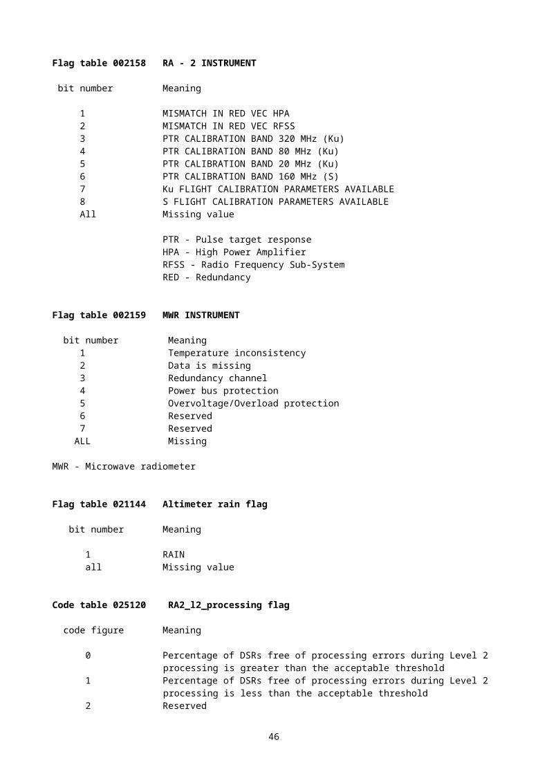
ANNEX TO 3.4.1
ADDITIONS FOR OCEANOGRAPHIC DATA
1) Proposed new BUFR descriptors for buoy data
Tab BUFR CREXRef Name Unit Scal
eRef Widt
hUnit Scal
eWidth
008xxx Artificial correction of sensor height to another value
Code 0 0 3 Code 0 1
022xxx Lagrangian drifter drogue status
Code 0 0 3 Code 0 1
008yyy Type of equipment Code 0 0 6 Code 0 2025yyy Battery voltage V 1 0 12 V 1 4025uuu Operator or manufacture
defined parameterNum 1 -16384 15 Num 1 5
Type of equipmentCode table 0 08 yyy
0 Sensor1 Transmitter2 Receiver3 Observing platform
4-62 Reserved63 Missing value
0 02 038 to be used instead of 0 22 yyy suggestion, will need renaming to include salinity reference, for example
0 02 038 element name
“Method of water temperature and/or salinity measurement”
0 08 xxxArtificial correction of sensor height to another value
Code figure Meaning0 Height is not corrected1 Height is artificially corrected to standard level using a formula2 Reserved3 Missing value
Note: Standard level is indicated by the descriptor of class 7, which immediately follows. Value of this class 7 descriptor is forced to missing in case height is not corrected. It is possible to indicate the real height of the sensor by preceding the descriptor by relevant class 7 descriptor.
0 22 yyyLagrangian drifter drogue status
Code figure Meaning0 Drogue is detached1 Drogue is attached2 Drogue status unknown3 Missing value
48

Proposed new template for buoy data
Proposed modifications appear in bold and red below
001003 - WMO region001020 - WMO region sub-area001005 - Buoy/platform identifier002001 - Type of station002036 - Buoy type002149 - Type of data buoy301011 - Date301012 - Time008021 - Time significance (value = “26" (time of last known position))301011 - Date301012 - Time008021 - Time significance (value = "missing")301021 - Latitude and longitude (high accuracy)027004 - Alternate latitude (high accuracy)028004 - Alternate longitude (high accuracy)007030 - Height of station above MSL001051 - Platform Transmitter ID (CCITT IA5)002148 - Data collection and/or Location system001012 - Platform drift direction001014 - Platform drift speed002040 - Method of removing platform direction and speed from current033022 - Quality of buoy satellite transmission033023 - Quality of buoy location033027 - Location quality class (range of radius of 66% confidence)022063 - Total water depth302021 - Waves302022 - Wind waves302023 - Swell waves008yyy – Type of equipment (observing platform)025yyy – Battery voltage008yyy – Type of equipment (transmitter)025yyy – Battery voltage008yyy – Type of equipment (receiver)025yyy – Battery voltage008yyy – Type of equipment – Value Missing = cancel002034 - Drogue type022yyy – Lagrangian drifter drogue status007070 - Drogue depth002190 - Lagrangian drifter submergence025086 - Depth correction indicator002035 - Cable length002168 - Hydrostatic pressure of lower end of cable020031 - Ice deposit (thickness)002038 - Method of water temperature and/or salinity measurement306004 - Digitization, depth/salinity method, depths/salinities/temperatures002030 - Method of current measurement306005 - Time/duration of current measurement, depths/directions/speeds007031 - Height of barometer above MSL008yyy – Type of equipment (sensor)012064 - Instrument temperature302001 - Pressure and pressure change008yyy – Type of equipment – Value Missing = cancel 007032 - Height of sensor above marine deck platform (for temp.&hum. measurement)007033 - Height of sensor above water surface (for temp.&hum. measurement)012101 - Dry-bulb temperature (scale 2)012103 - Dew-point temperature (scale 2)013003 - Relative humidity
49
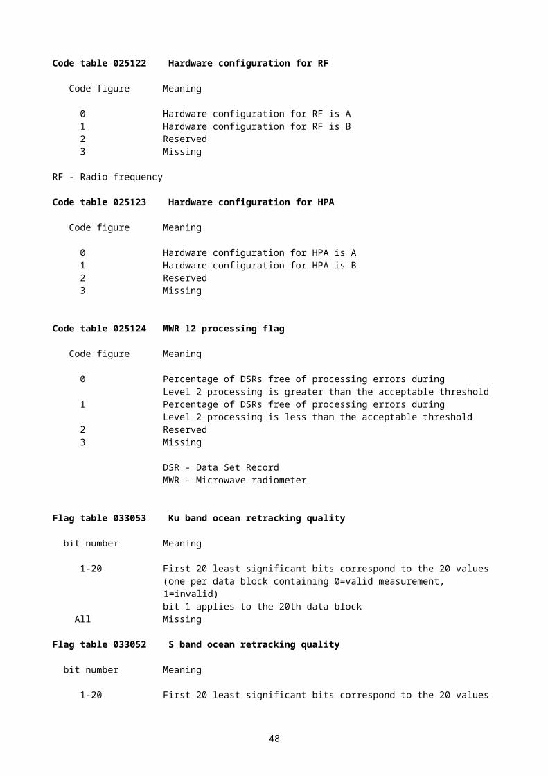
007032 - Height of sensor above marine deck platform (for wind measurement)007033 - Height of sensor above water surface (for wind measurement)008xxx – Artificial correction of sensor height to another value007033 - Height of sensor above water surface (here height of anemometer to which it is artificially corrected)002169 - Anemometer type002002 - Type of instrumentation for wind measurement008021 - Time significance (value = “2" (time averaged))004025 - Time period in minutes011001 - Wind direction011002 - Wind speed008021 - Time significance (value = "missing”)004025 - Time period in minutes011043 - Maximum wind gust direction011041 - Maximum wind gust speed008xxx – Artificial correction of sensor height to another value (set to missing to reset previous value)007033 - Height of sensor above water surface (set to missing to cancel previous value)007032 - Height of sensor above marine deck platform (for precipitation measurement)004024 - Time period in hours013011 - Total precipitation007032 - Height of sensor above marine deck platform (set to missing to cancel the previous value)008021 - Time significance (value = “3" (accumulated))004024 - Time period in hours014021 - Global radiation, integrated over period specified008021 - Time significance (value = "missing”)025yyy – Operator or manufacturer defined parameter (#1)025yyy – Operator or manufacturer defined parameter (#2)025yyy – Operator or manufacturer defined parameter (#3)
2) Requirements by the Ship Of Opportunity Programme (SOOP)
Additions to BUFR tables required
Additions needed to Common code table C-3, Instrument type for water profile measurement with fall rate equation coefficients
Code figure forIxIxIx
Code figure for BUFR(code table 0 22 067)
Instrument Make Equation Coefficientsa b
855 855 Profiling Float, NINJA, no conductivity sensor
Not applicable
856 856 Profiling Float, NINJA, SBE conductivity sensor
Not applicable
857 857 Profiling Float, NINJA, FSI conductivity sensor
Not applicable
858 858 Profiling Float, NINJA, TSK conductivity sensor
Not applicable
900 900 Sippican T-12 XBT 9.727 -0.0000473
Additions needed to Common code table C-4, Water temperature profile recorder types
Code figure forXRXR
Code for BUFR(Code table 0 22 068)
Recorder type
70 70 CSIRO Devil-1 XBT acquisition system71 71 CSIRO Devil-2 XBT acquisition system
50

ANNEX TO 3.4.2
CLARIFICATION TO BUFR REGULATION
Note (1) to Class 04 should be modified from “shall be indicated…” to: "… may be indicated …".
ANNEX TO 3.4.3
FOR SHIP TEMPLATES
Add Note in Templates of SHIP to descriptor 0 01 012:
*Means course made good (average course over the ground) during the three hours preceding the time of observation
Add Note in Templates of SHIP to descriptor 0 01 013:
*Means speed made good (average speed over the ground) during the three hours preceding the time of observation
Add a Note in Table B to descriptors 0 01 012 and 0 01 013 indicating the parameters may have different meanings and the corresponding value may be integrated on different periods.
51
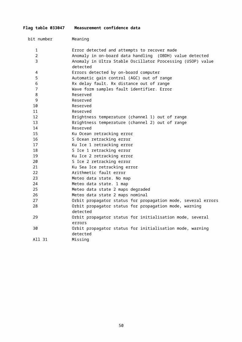
ANNEX TO 3.4.4
BUFR TEMPLATES FOR VERTICAL SOUNDING DATA WITH DESCRIPTION OF RADIOSONDE POSITION DURING THE ASCENT
1 BUFR templates for PILOT, PILOT SHIP, PILOT MOBIL
a) with pressure as the vertical coordinate
Identification and instrumentation3 01 001 0 01 001 WMO block number Numeric
0 01 002 WMO station number Numeric0 01 011 Ship or mobile land station identifier CCITT IA50 02 011 Radiosonde type Code table0 02 014 Tracking technique/status of system used Code table0 02 003 Type of measuring equipment used Code table
Nominal date/time, horizontal and vertical coordinates of launch site
3 01 011 0 04 001 Year Year0 04 002 Month Month0 04 003 Day Day
3 01 012 0 04 004 Hour Hour0 04 005 Minute Minute
3 01 021 0 05 001 Latitude (high accuracy) Degree, scale 50 06 001 Longitude (high accuracy) Degree, scale 5
0 07 030 Height of station ground above mean sea level m, scale 10 07 031 Height of barometer above mean sea level m, scale 10 07 007 Height of release of sonde above mean sea level m0 33 024 Station elevation quality mark (for mobile stations) Code table
Date/time of the launch0 08 021 Time significance
(value = 18 (launch time))Code table
3 01 011 0 04 001 Year Year0 04 002 Month Month0 04 003 Day Day
3 01 012 0 04 004 Hour Hour0 04 005 Minute Minute
Level data1 07 000 Delayed replication of 7 descriptors 0 31 001 Delayed descriptor replication factor Numeric
Data from a single level0 04 016 Time increment in seconds (since launch time)0 08 001 Vertical sounding significance Flag table0 07 004 Pressure Pa, scale –10 05 011 Latitude increment since launch site (high accuracy) Degree, scale 50 06 011 Longitude increment since launch site (high
accuracy)Degree, scale 5
0 11 001 Wind direction Degree true0 11 002 Wind speed m s-1, scale 1
Wind shear data0 08 001 Vertical sounding significance Flag table0 07 004 Pressure Pa, scale –1
52
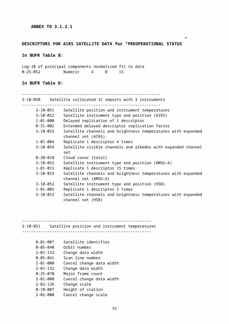
3 01 023 0 05 002 Latitude (coarse accuracy) Degree, scale 20 06 002 Longitude (coarse accuracy) Degree, scale 2
0 11 061 Absolute wind shear in 1 km layer below m s-1, scale 10 11 062 Absolute wind shear in 1 km layer above m s-1, scale 1
b) with height as the vertical coordinate
Identification and instrumentation3 01 001 0 01 001 WMO block number Numeric
0 01 002 WMO station number Numeric0 01 011 Ship or mobile land station identifier CCITT IA50 02 011 Radiosonde type Code table0 02 014 Tracking technique/status of system used Code table0 02 003 Type of measuring equipment used Code table
Nominal date/time, horizontal and vertical coordinates of launch site
3 01 011 0 04 001 Year Year0 04 002 Month Month0 04 003 Day Day
3 01 012 0 04 004 Hour Hour0 04 005 Minute Minute
3 01 021 0 05 001 Latitude (high accuracy) Degree, scale 50 06 001 Longitude (high accuracy) Degree, scale 5
0 07 030 Height of station ground above mean sea level m, scale 10 07 007 Height of release of sonde above mean sea level m0 33 024 Station elevation quality mark (for mobile stations) Code table
Date/time of the launch0 08 021 Time significance
(value = 18 (launch time))Code table
3 01 011 0 04 001 Year Year0 04 002 Month Month0 04 003 Day Day
3 01 012 0 04 004 Hour Hour0 04 005 Minute Minute
Level data1 07 000 Delayed replication of 7 descriptors 0 31 001 Delayed descriptor replication factor Numeric
Data from a single level0 04 016 Time increment in seconds (since launch time)0 08 001 Vertical sounding significance Flag table0 07 004 Pressure Pa, scale –10 05 011 Latitude increment since launch site (high accuracy) Degree, scale 50 06 011 Longitude increment since launch site (high
accuracy)Degree, scale 5
0 11 001 Wind direction Degree true0 11 002 Wind speed m s-1, scale 1
Wind shear data0 08 001 Vertical sounding significance Flag table0 07 009 Geopotential height gpm3 01 023 0 05 002 Latitude (coarse accuracy) Degree, scale 2
0 06 002 Longitude (coarse accuracy) Degree, scale 2
53
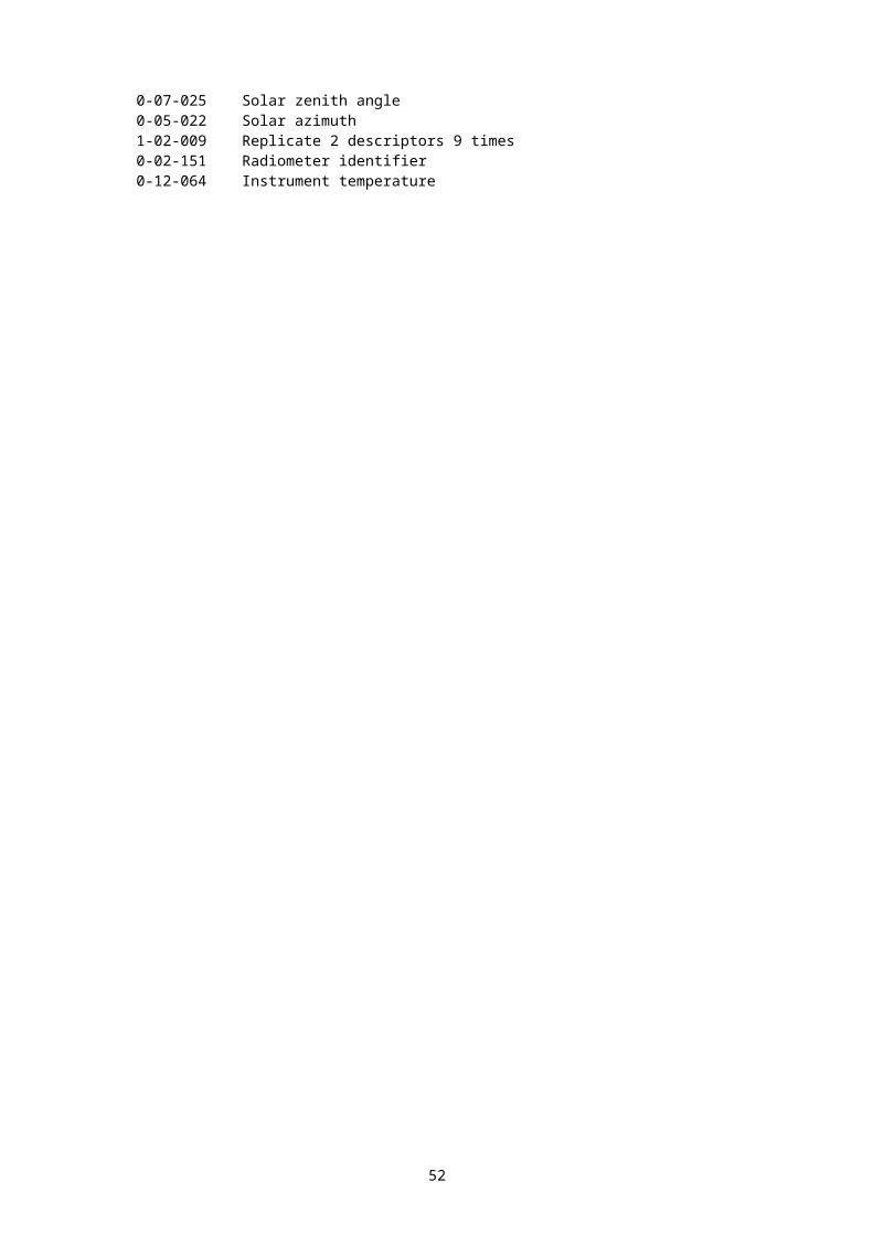
0 11 061 Absolute wind shear in 1 km layer below m s-1, scale 10 11 062 Absolute wind shear in 1 km layer above m s-1, scale 1
Notes: (1) If horizontal coordinates of the sonde are not available, latitude and longitude (coarse accuracy) of the location of launch shall be reported for 3 01 023.
2.2 BUFR templates for TEMP, TEMP DROP, TEMP SHIP, TEMP MOBIL
Identification and instrumentation3 01 001 0 01 001 WMO block number Numeric
0 01 002 WMO station number Numeric0 01 011 Ship or mobile land station identifier CCITT IA50 01 006 Aircraft identifier (for dropsondes) CCITT IA50 02 011 Radiosonde type Code table0 02 013 Solar and infrared radiation correction Code table0 02 014 Tracking technique/status of system used Code table0 02 003 Type of measuring equipment used Code table
Nominal date/time, horizontal and vertical coordinates of launch site
3 01 011 0 04 001 Year Year0 04 002 Month Month0 04 003 Day Day
3 01 012 0 04 004 Hour Hour0 04 005 Minute Minute
3 01 021 0 05 001 Latitude (high accuracy) Degree, scale 50 06 001 Longitude (high accuracy) Degree, scale 5
0 07 030 Height of station ground above mean sea level m, scale 10 07 031 Height of barometer above mean sea level m, scale 10 07 007 Height of release of sonde above mean sea level m0 33 024 Station elevation quality mark (for mobile stations) Code table
Sea water temperature0 22 043 Sea/water temperature (for ship stations) K, scale 2
Cloud data0 08 002 Vertical significance Code table0 20 011 Cloud amount (of low or middle clouds Nh) Code table0 20 013 Height of base of cloud (h) m, scale –10 20 012 Cloud type (low clouds CL) Code table0 20 012 Cloud type (middle clouds CM) Code table0 20 012 Cloud type (high clouds CH) Code table
Date/time of the launch0 08 021 Time significance
(value = 18 (radiosonde launch time))Code table
3 01 011 0 04 001 Year Year0 04 002 Month Month0 04 003 Day Day
3 01 012 0 04 004 Hour Hour0 04 005 Minute Minute
Level data1 10 000 Delayed replication of 10 descriptors 0 31 001 Delayed descriptor replication factor Numeric
Data from a single level
54
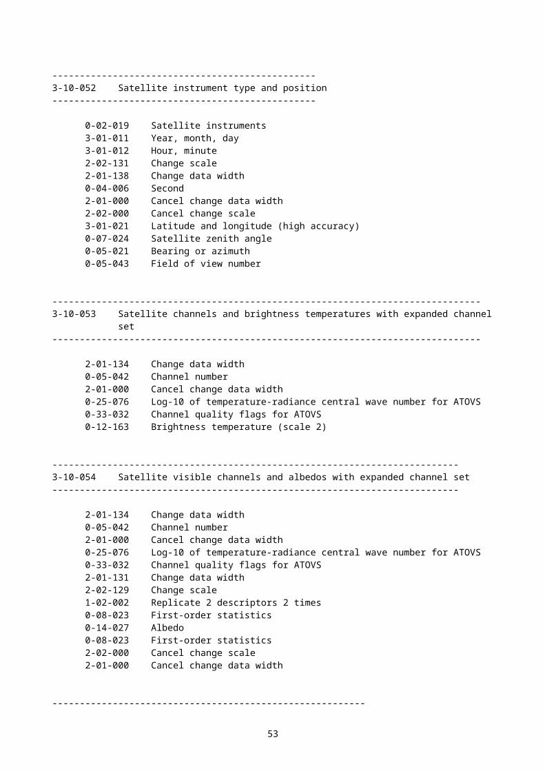
0 04 016 Time increment (since the launch time) Seconds0 08 001 Vertical sounding significance Flag table0 07 004 Pressure Pa, scale –10 10 009 Geopotential height gpm0 05 011 Latitude increment since launch site (high accuracy) Degree, scale 50 06 011 Longitude increment since launch site (high
accuracy)Degree, scale 5
0 12 101 Temperature/dry-bulb temperature (scale 2) K, scale 20 12 103 Dew-point temperature (scale 2) K, scale 20 11 001 Wind direction Degree true0 11 002 Wind speed m s-1, scale 1
Wind shear data0 08 001 Vertical sounding significance Flag table0 07 004 Pressure Pa, scale –13 01 023 0 05 002 Latitude (coarse accuracy) Degree, scale 2
0 06 002 Longitude (coarse accuracy) Degree, scale 20 11 061 Absolute wind shear in 1 km layer below m s-1, scale 10 11 062 Absolute wind shear in 1 km layer above m s-1, scale 1
Notes: (1) If horizontal coordinates of the sonde are not available, latitude and longitude (high accuracy) of the location of launch shall be reported for 3 01 023.
55
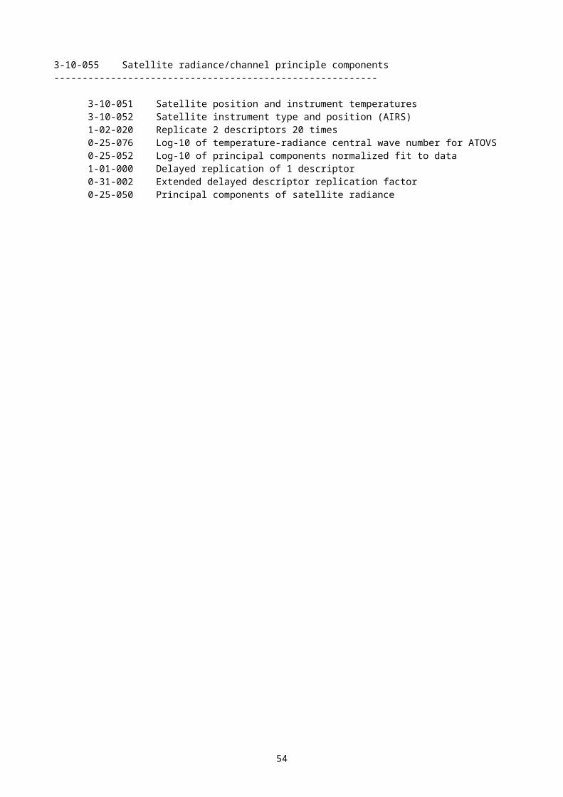
ANNEX TO 3.4.5
ADDITION TO CODE TABLES
Vertical significance 0 08 002 Only adding two entries to 0 08 002
10 Cloud layer with base below and top above the station11 Cloud layer with base and top below station level
To clarify the meaning o existing 0 08 002 entries
1 First non-Cb significant layer2 Second non-Cb significant layer3 Third non-Cb significant layer
Validation of BUFR template for SYNOP (and SYNOP MOBIL)
To modify the name of 0 20 014 to read (in Template):Height of top of the clouds above mean sea level.
56
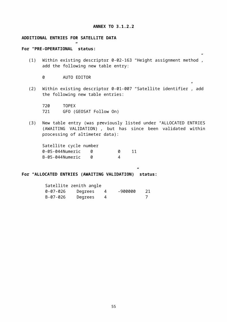
Example of BUR template expressing the significant cloud layers using delayed replication
BUFR template for SYNOP and SYNOP MOBIL data
Surface station identification, time, horizontal and vertical coordinates
Unit, scale
3 01 001 0 01 001 WMO block number II Numeric, 00 01 002 WMO station number iii Numeric, 0
0 01 015 Station or site name CCITT IA5, 00 01 011 Mobile land station identifier
D.....D = missing for fixed land stations
CCITT IA5, 0
0 01 003 WMO region number Code table, 00 02 001 Type of station Code table, 03 01 011 0 04 001 Year Year, 0
0 04 002 Month Month, 00 04 003 Day YY Day, 0
3 01 012 0 04 004 Hour GG Hour, 00 04 005 Minute gg Minute, 0
3 01 021 0 05 001 Latitude (high accuracy) Degree, 50 06 001 Longitude (high accuracy) Degree, 5
0 07 030 Height of station ground above msl m, 10 07 031 Height of barometer above msl m, 10 33 024 Station elevation quality mark
im = missing for fixed land stations
Code table, 0
Pressure data3 02 001 0 10 004 Pressure
PoPoPoPo
Pa, –1
0 10 051 Pressure reduced to mean sea level PPPP Pa, –10 10 061 3-hour pressure change
ppp Pa, –1
0 10 063 Characteristic of pressure tendency a Code table, 00 07 004 Pressure (standard level)
a3 = 925, 850, 700, ..hPa = missing for lowland stations
Pa, –1
0 10 009 Geopotential height of the standard level hhh = missing for lowland stations
gpm, 0
Temperature and humidity data0 07 032 Height of sensor above local ground
(for temperature measurement) m, 2
0 12 101 Temperature/dry-bulb temperature (sc. 2) snTTT K, 20 12 103 Dew-point temperature (sc. 2) snTdTdTd K, 20 13 003 Relative humidity %, 0
Visibility data 0 07 032 Height of sensor above local ground
(for visibility measurement) m, 2
0 20 001 Horizontal visibility VV m, –1Precipitation past 24 hours
57
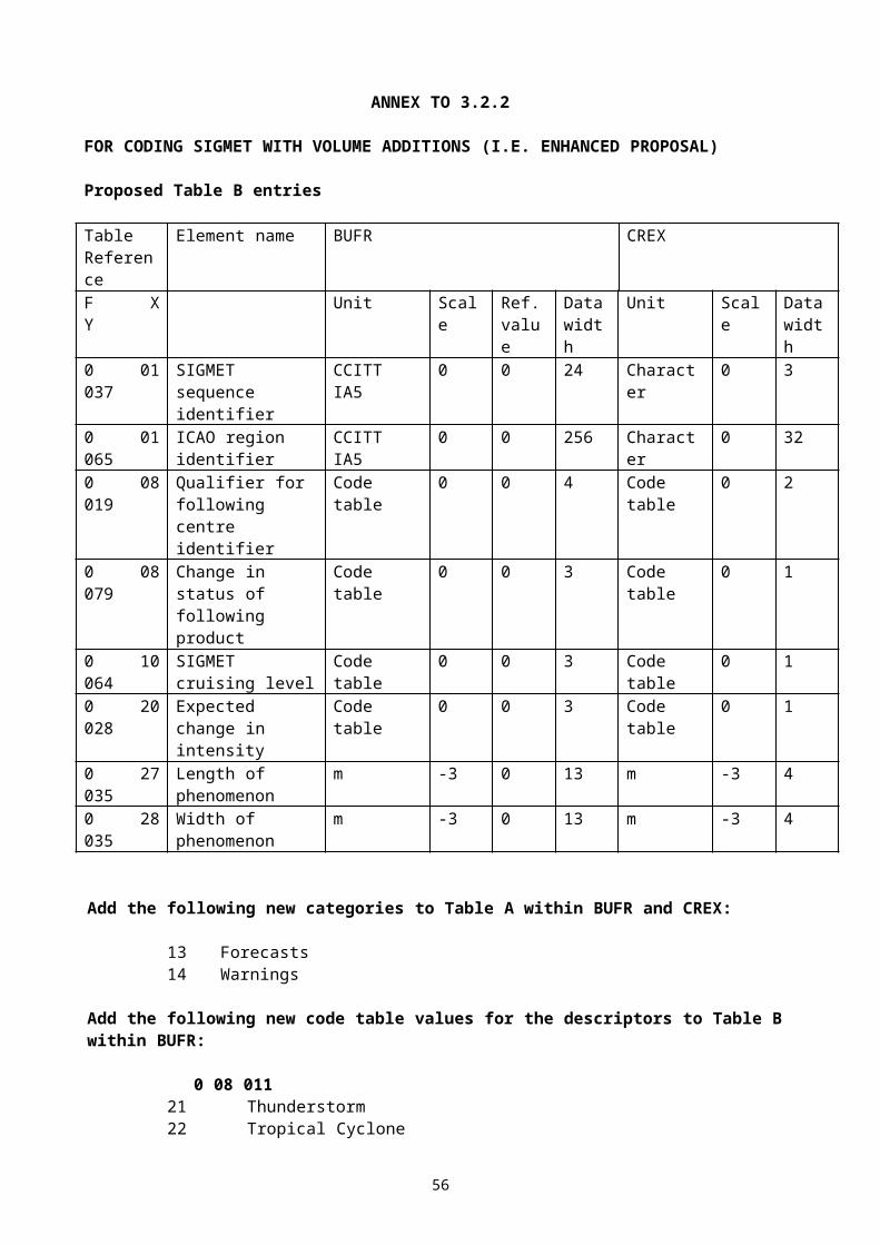
0 07 032 Height of sensor above local ground(for precipitation measurement)
m, 2
0 13 023 Total precipitation past 24 hours RRRR trace = - 0.1 (gr. 7RRRR)
kg m-2, 1
0 07 032 Height of sensor above local ground(set to missing to cancel the previous value)
m, 2
Cloud data3 02 004 0 20 010 Cloud cover (total) N
If N = 9, /, then 0 20 010 = missing. %, 0
0 08 002 Vertical significance if only CL are observed, 0 08 002 = 7 (low cloud),if only CM are observed, 0 08 002 = 8 (middle cloud),if only CH are observed, 0 08 002 = 9 (high cloud),if N = 9, then 0 08 002 = 5,if N = 0 or /, then 0 08 002 = missing;else 0 08 002 = 0
Code table, 0
0 20 011 Cloud amount (of low or middle clouds) Nh
If N = 0, then 0 20 011 = 0,if N = 9, then 0 20 011 = 9,if N = /, then 0 20 011 = missing.
Code table, 0
0 20 013 Height of base of cloud hIf N = 0 or /, then 0 20 013 = missing.If clouds with bases below and tops above station level are reported, 0 20 013 = missing or has a negative value.
m, –1
0 20 012 Cloud type (low clouds) CL
0 20 012 = CL + 30,if N = 0, then 0 20 012 = 30,if N = 9 or /, then 0 20 012 = 62.
Code table, 0
0 20 012 Cloud type (middle clouds) CM
0 20 012 = CM + 20,if N = 0, then 0 20 012 = 20,if N = 9 or / or CM = /, then 0 20 012 = 61.
Code table, 0
0 20 012 Cloud type (high clouds) CH
0 20 012 = CH + 10,if N = 0, then 0 20 012 = 10,if N = 9 or / or CH = /, then 0 20 012 = 60.
Code table, 0
1 01 000 Delayed replication of 1 descriptor 0 31 001 Delayed descriptor replication factor
If sky clear (N = 0), then 0 31 001 = 0 (no significant cloud layer data)
Numeric, 0
3 02 005 0 08 002 Vertical significanceIn any Cb layer, 0 08 002 = 4 , else:in the first replication: if N = 9, then 0 08 002 = 5,if N = /, then 0 08 002 = missing,else 0 08 002 = 1;in the other replications 0 08 002 = 2, 3, 4.
Code table, 0
0 20 011 Cloud amount Ns
In the first replication: If N = /, then 0 20 011 = missing,else 0 20 011 = Ns;
Code table, 0
58
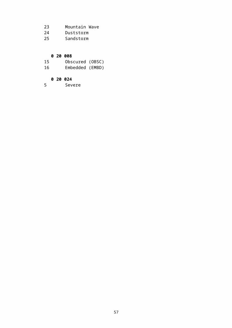
in the other replications 0 20 011 = Ns.0 20 012 Cloud type C
if N = 9, /, then 0 20 012 = missing,else 0 20 012 = C.
Code table, 0
0 20 013 Height of base of cloud hshs
If clouds with bases below and tops above station level are reported, 0 20 013 = missing or has a negative value.
m, -1
Clouds with bases below station level(SYNOP, Section 4)
1 05 000 Delayed replication of 5 descriptors 0 31 001 Delayed descriptor replication factor
If no clouds with bases below station level areobserved, then 0 31 001 = 0
Numeric, 0
0 08 002 Vertical significance = 10 or 11 Code table, 00 20 011 Cloud amount N' Code table, 00 20 012 Cloud type C' Code table, 00 20 014 Height of top of cloud above mean sea level H'H' m, -1, 40 20 017 Cloud top description Ct Code table, 0
State of ground, snow depth, ground minimum temperature
0 20 062 State of ground (with or without snow) E or E' If E = <0, ... , 9>, then 0 20 062 = E, if E' = <0, ... , 9>, then 0 20 062 = E' + 10, if state of ground is not reported, 0 20 062 = missing.
Code table, 0
0 13 013 Total snow depth sss no snow cover = 0 less than 0.005 m = - 0.01 (sss = 997) not continuous = - 0.02 (sss = 998)If snow depth not reported, 0 13 013 = missing.
m, 2
0 12 113 Ground minimum temperature, sc.2, snTgTg
past 12 hours K, 2
Present and past weather 0 20 003 Present weather
ww Code table, 0
0 04 024 Time period At 00, 06, 12, 18 UTC = - 6.At 03, 09,15, 21 UTC = - 3.
Hour, 0
0 20 004 Past weather (1) W1 Code table, 00 20 005 Past weather (2) W2 Code table, 0
Evaporation measurement0 04 024 Time period in hours = - 24 Hour, 00 02 004 Type of instrument for evaporation or iE
crop type for evapotranspirationCode table, 0
0 13 033 Evaporation /evapotranspiration EEE kg m-2, 1Sunshine data
0 04 024 Time period in hours = - 24 Hour, 00 14 031 Total sunshine in minutes
SSS Minute, 0
Radiation data0 04 025 Time period in minutes = - 60 Minute, 0
59
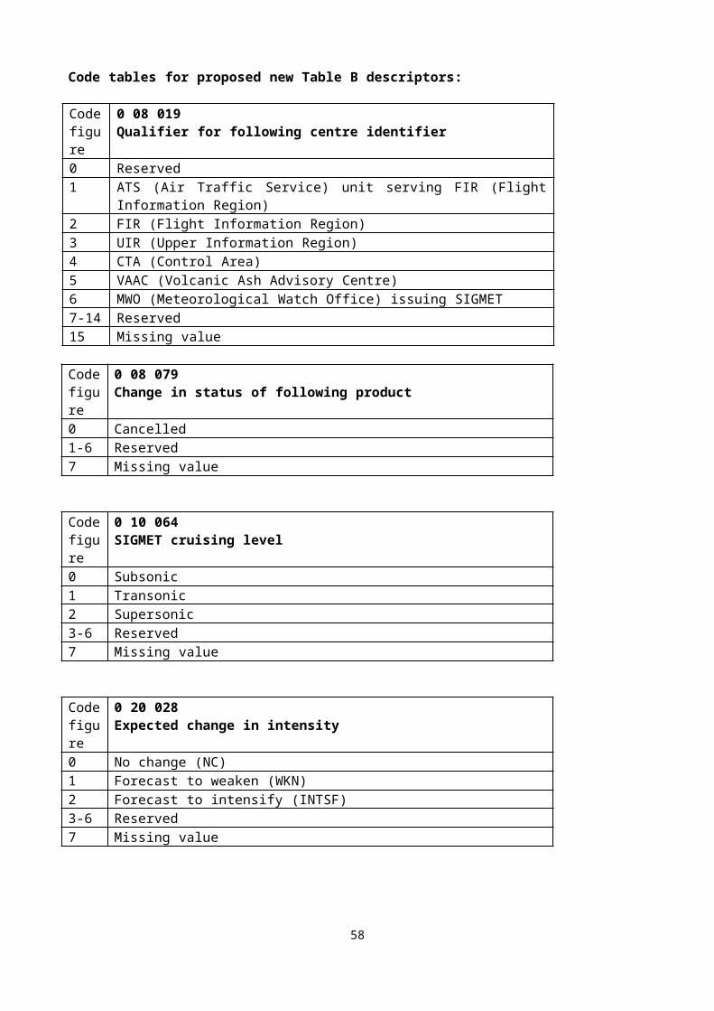
0 14 002 Long-wave radiation, integrated over period specified 553SS 4FFFF or 553SS 5FFFF J m-2, -3
0 14 004 Short-wave radiation, integrated over period specified 553SS 6FFFF
J m-2, -3
0 14 016 Net radiation, integrated over period specified 553SS 0FFFF or 553SS 1FFFF J m-2, -4
0 14 028 Global solar radiation (high accuracy), integrated over period specified 553SS 2FFFF
J m-2, -2
0 14 029 Diffuse solar radiation(high accuracy), integrated over period specified 553SS 3FFFF
J m-2, -2
0 14 030 Direct solar radiation (high accuracy), integrated over period specified 55408 4FFFF
J m-2, -2
Precipitation measurement0 07 032 Height of sensor above local ground
(for precipitation measurement) m, 2
1 02 002 Replicate next 2 descriptors 2 times0 04 024 Time period in hours
tR Hour, 0
0 13 011 Total precipitation / total water equivalent RRR of snow no precipitation = 0 trace = - 0.1
kg m-2, 1
Extreme temperature data0 07 032 Height of sensor above local ground
(for temperature measurement) m, 2
0 04 024 Time period in hours Hour, 00 04 024 Time period in hours (see Note 1)
(= 0, if the period ends at the time of observation)Hour, 0
0 12 111 Maximum temperature at height and over periodspecified snTxTxTx
K, 2
0 04 024 Time period in hours Hour, 00 12 112 Minimum temperature at height and over period
specified snTnTnTn
K, 2
Wind data0 07 032 Height of sensor above local ground
(for wind measurement) m, 2
0 02 002 Type for instrumentation for wind measurement iw
Flag table, 0
0 08 021 Time significance = 2 (time averaged) Code table, 00 04 025 Time period = - 10
(or number of minutes after a significant change of wind, if any)
Minute, 0
0 11 001 Wind direction dd If dd = 00 (calm) or dd = 99 (variable), 0 11 001 = 0.
Degree true, 0
0 11 002 Wind speed ff
m s-1, 1
60
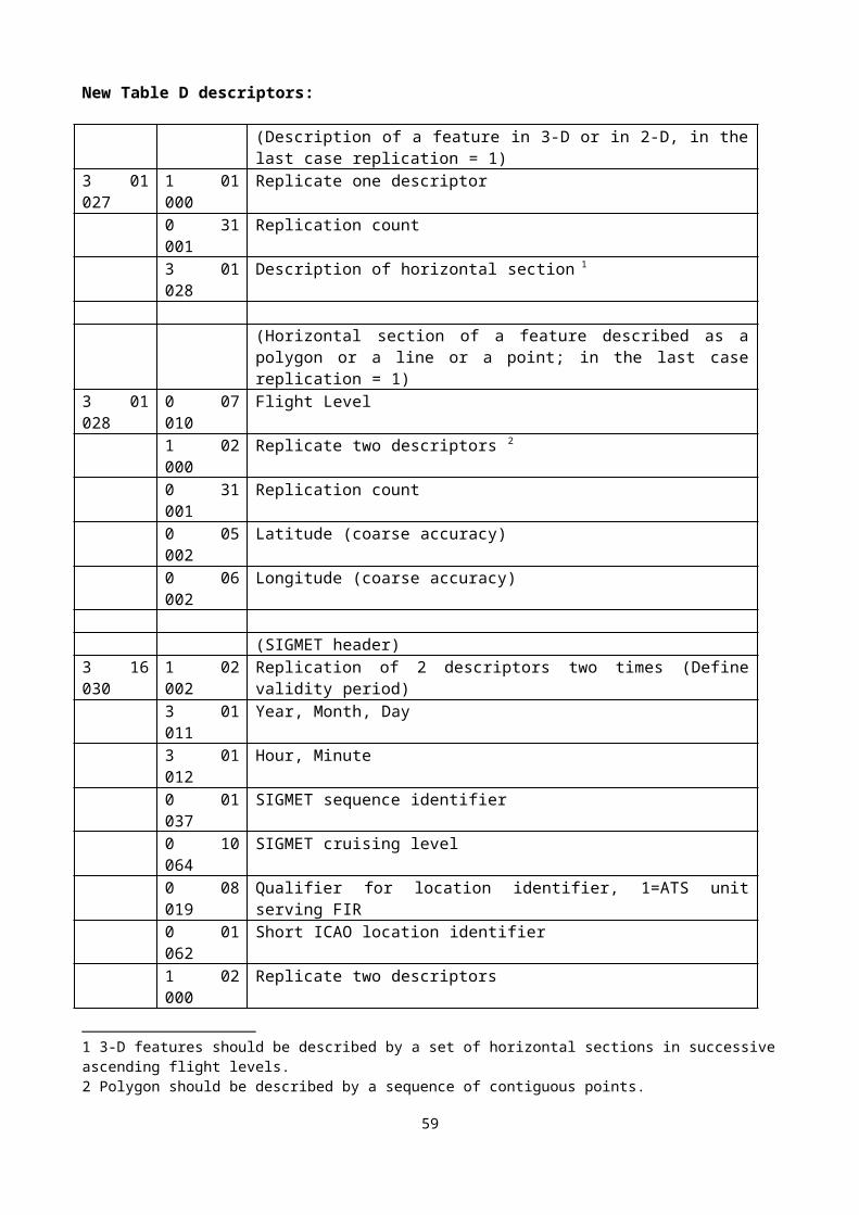
0 08 021 Time significance (set to missing to cancel the previous value)
Code table, 0
1 03 002 Replicate next 3 descriptors 2 times0 04 025 Time period Minute, 00 11 043 Maximum wind gust direction Degree true, 00 11 041 Maximum wind gust speed e.g. fmfm and fxfx
(gr. 910fmfm and gr. 911fxfx)m s-1, 1
Notes: 1) Within RA-IV, the maximum temperature at 1200 UTC is reported for the previous calendar
day (i.e. the ending time of the period is not equal to the nominal time of the report). To construct the required time range, descriptor 004024 has to be included two times. If the period ends at the nominal time of the report, value of the second 004024 shall be set to 0.
61
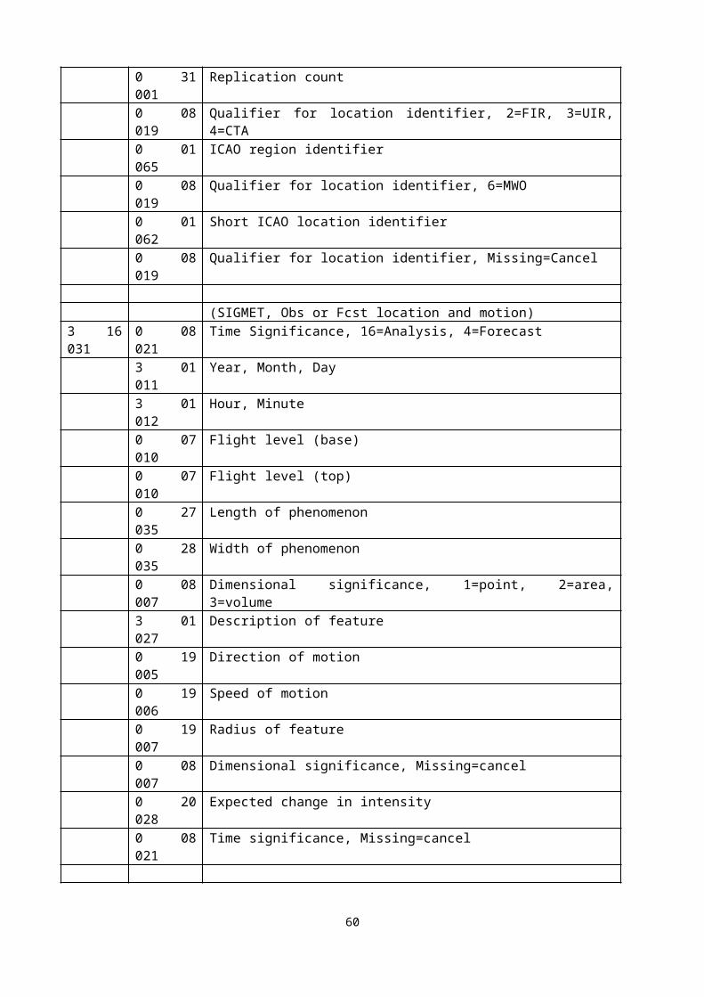
ANNEX TO 3.5.4
Proposed modified Section 1 for BUFR Edition 4 for full date inclusion:
13-14 Year (4 digits) |15 Month |16 Day | Most typical for the BUFR message content17 Hour |18 Minute |19 Second |20- Reserved for local use by ADP centres
ANNEX TO 3.5.5
Modify regulation 94.1.3 to say:
94.1.3 Each section included in the code form shall always contain an integer multiple of 8 bits (octet). This rule shall be applied by appending bits set to zero to the section where necessary.
62
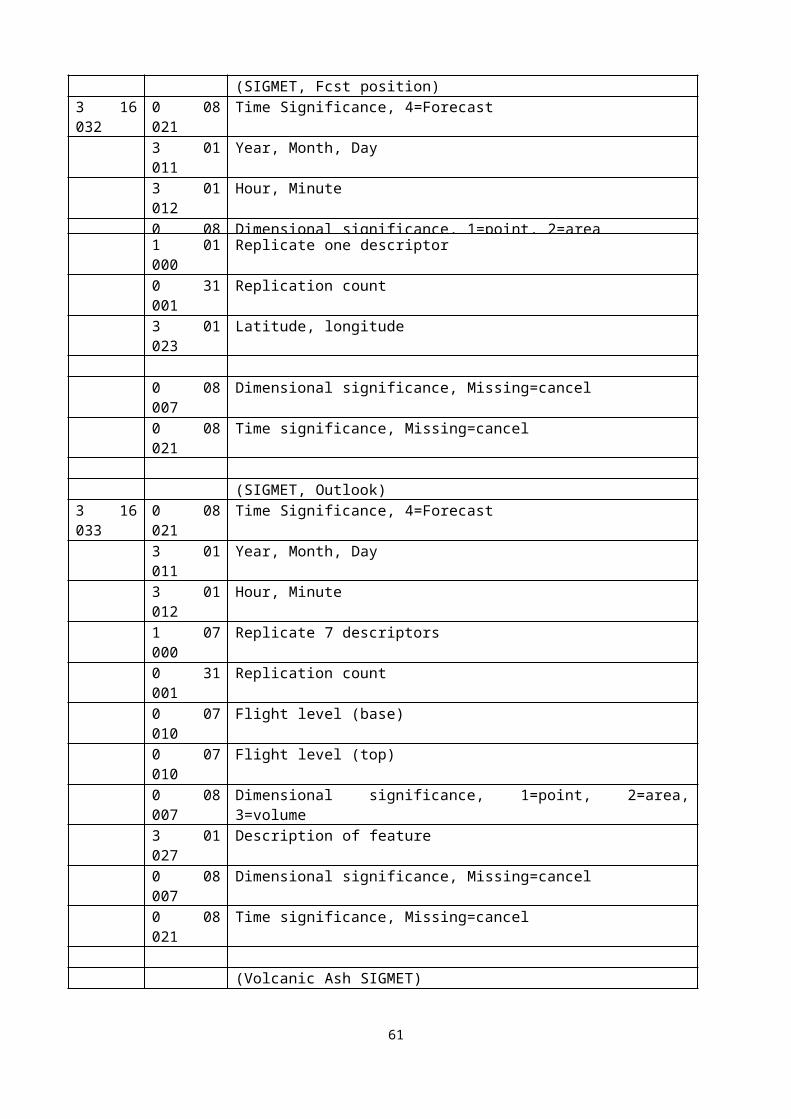
ANNEX TO 5
MODIFICATIONS TO THE LAYER 3 OF THE GRIB2 GUIDE
Text to be replaced at page 74 (after formula giving the pressure at a given sigma level)
The hybrid coordinate system has been introduced in numerical models to have both sigma-type levels near the earth and pressure levels at the top of the atmosphere. The above formula is generalized as follows:
Ph = ah Psfc + bh
Hybrid vertical coordinate values, when present, are encoded as the pair of numbers ah and bh in IEEE 32-bit floating point format. Each pair …(remaining text unchanged)
NOTE: also change “a ” and “b P” references in following expanded example (p. 75) to (a1, b1) … (a10, b10).
Complex packing
Note pages 80 and 85 within the Guide: text to be inserted as a substitute to Cliff remarks at these pages (end of 3.3.1.1 and end of 3.3.2.1).
As pointed out in the GRIB2 Manual, complex packing for grid-point is intended to reduce data section size as compared to simple packing. This is achieved at the expense of extra descriptors per group. In order to keep the volume of these descriptors as low as possible, group widths and lengths have their minimum value subtracted. As a complement, lengths may be scaled using the length increment feature.
This may be used in conjunction with splitting algorithm to determine groups of data. Efficient algorithms with a good quality/price ratio are based on the determination of groups starting from a basic length, say B, and possible extensions of either B or a shorter (incremental) length I. For example, B and I could be 15 and 3, respectively.
In such a case, all groups (but the last one) will have a minimum length of B and length increments multiple of I (assuming B is a multiple of I, which is easy to choose). So B would be stored in octets 38-41, I in octet 42, and the effective length of last groups (reference for group lengths not removed) in octets 43-46.
Finally, the number of bits NL necessary to store the scaled group lengths (the Kn values in Note 14 of the Manual) will be stored in octet 47. Note that as soon as I is bigger than 1, N L is reduced relative to using an increment of 1, leading to save space in Data Section.
The Kn values are stored in Data Section for all NG groups. The encoded value of Kn for n= NG is not relevant for decoding, and a zero value may be used.
Spatial differencing
Note page 84 of the Guide. All modifications to be done on this page:
63
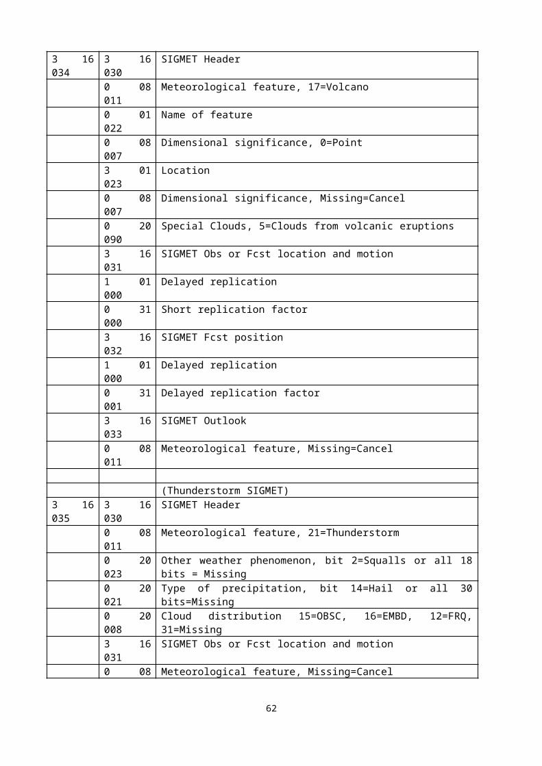
Change start of first sentence of first paragraph as follows:
“For first order spatial differencing, a field of scaled values f (integers) is replaced by….”
In second paragraph, change 3rd sentence as follows:
“The overall minimum of the difference values will usually be negative therefore the Note (4) of Data Template 7.3 about the sign bit applies.”
64

ANNEX TO 7.1.2
In order to facilitate the processing of requests for allocation of new table entries by the Secretariat, the Team agreed to a standard format for definition of new descriptors when passing the information in document or email.
The format should be:
In Word table format as (possible in Attached file, ftp, etc..):
TABLE REFERENCE
TABLE
ELEMENT NAME
BUFR CREX
UNIT SCALE REF. VALUE
DATA WIDTH
(Bits)UNIT SCALE
DATAWIDTH
(Characters)F X Y0 01 001 WMO block
numberNumeri
c0 0 7 Numeri
c0 2
0 01 002 WMO station number
Numeric
0 0 10 Numeric
0 3
Or in ASCII as (column separated by space, but inside name with dash):
0 01 001 WMO-Block-number Numeric 0 0 7 Numeric 0 2
or as (column separated by commas, but inside name with space):
0,01,001,WMO Block number, Numeric,0,0,7,Numeric,0,2
65
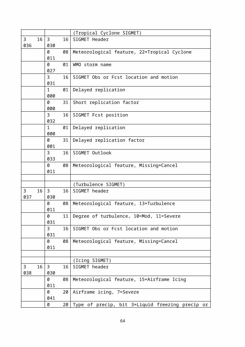
ANNEX LIST OF ACRONYMSACARS AirCraft Addressing and Reporting SystemADS Astrophysics Data System (USA)AFWA Air Force Weather AgencyAIRS Advanced Infra-Red SounderAMDAR Aircraft Meteorological Data RelayAMSU Advanced Microwave Sounding UnitANSI American National Standards InstituteAPI Application Program InterfaceAWIPS Advanced Weather Interactive Processing SystemAWS Automatic Weather StationATSR Along Tack Scanning RadiometerBUFR Binary Universal Form for data RepresentationCBS Commission for Basic SystemsCBS-Ext.(98) Extraordinary session of CBS held in 1998CCl Commission for Climatology (WMO)CIMO Commission for Instruments and Methods of ObservationsCOST European Co-Operation in the field of Scientific and Technical researchCREX Character Representation form for data EXchangeDBCP Drifting Buoy Cooperation PanelDBMS Data Base Management SystemDCP Data Collection PlatformDIF Directory Interchange FormatDPFS Data Processing and Forecasting SystemsDRT Data Representation TemplateDT Data TemplateDWD Deutscher Wetter DienstEANPG European Air Navigation Planning GroupEARS EUMETSAT ATOVS Retransmission ServiceEC Executive Council of the WMOECMWF European Centre for Medium-range Weather ForecastEGOWS European Group on Operational Worskstation SystemsEPS Ensemble Prediction SystemESA European Space AgencyET Expert TeamET/EDF Expert Team on Evolution of Data FormatsET/DR&C Expert Team on Data Representation and CodesEUMETNET European Meteorological NetworksEUMETSAT EUropean organisation for the exploitation of METeorological SATellitesFNMOC Fleet Numerical Meteorology and Oceanography CentreFORTRAN FORmula TRANslation FTP File Transfer ProtocolGDPS Global Data Processing SystemGDT Grid Definition TemplateGIF Graphic Interchange FormatGIS Geographic Information SystemGOS Global Observing SystemGRIB 1 Processed data in the form of GRId-point values expressed in Binary form - GRIB
Edition 1GRIB 2 General Regularly distributed Information in Binary form - GRIB Edition 2GTS Global Telecommunications SystemHTML Hyper Text Markup LanguageICAO International Civil Aviation OrganisationICT Implementation/Coordination Team (of CBS)ICT/DRC Implementation/Coordination Team on Data Representation and Codes ID IdentifierIEC International Electrotechnical CommissionIEEE Institution of Electrical and Electronics EngineersIOC International Oceanographic CommissionISO International Standards OrganizationJCOMM Joint WMO/IOC Technical Commission for Oceanography and Marine Meteorology
66
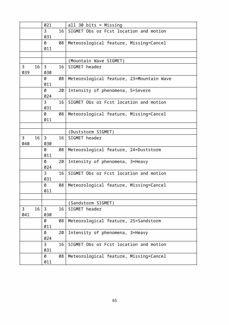
JMA Japan Meteorological AgencyJPEG Joint Photographic Experts Group formatLINUX Not an acronym – name of an operating systemMS/DOS /Disk Operating SystemMSG METEOSAT Second GenerationMSS Message Switching SystemMTDCF Migration to Table Driven Code FormsMTN Main Telecommunications Network (of the GTS)NASA National Aeronautics and Space AdministrationNCDC National Climatic Data Centre (USA)NCEP National Centre for Environment Prediction (USA)NESDIS National Environmental Satellite Data and Information ServiceNMC National Meteorological CentreNMHS National Meteorological or Hydrological ServiceNMS National Meteorological ServiceNWP Numerical Weather PredictionNWS National Weather ServiceOMF weather Observation Markup FormatOPAG Open Programme Area Group (of CBS)OPAG-ISS Open Programme Area Group on Information Systems and ServicesPDT Product Definition TemplatePNG Portable Network GraphicRA Regional Association (WMO)RASS Radio Acoustic Sounding SystemRDBC Regional Data Bank CentreRSMC Regional Specialised Meteorological CentreRTH Regional Telecommunication HubSGDR&C Sub-Group on Data Representation and Codes (CBS)SGML Standard Generalized Markup LanguageSI System InternationalSOOP Ship Of Opportunity ProgrammeSST Sea Surface TemperatureTCP Tropical Cyclone ProgrammeTCP/IP Transport Control Protocol/Internet ProtocolTDL Techniques Development LaboratoryTIFF Tagged Image File FormatUKMO United Kingdom Meteorological OfficeUNIX Not an acronym – name of an operating systemUTC Universal Time CoordinateVOS Voluntary Observing ShipWAFC World Area Forecasting Centre (ICAO)WAFS World Area Forecasting SystemWGDM Working Group on Data Management (CBS)WGS Working Group on StandardsWMO World Meteorological OrganizationWWW World Weather WatchW3C World Wide Web ConsortiumXBT eXpendable Bathy ThermographXCTD eXpendable Conductivity Temperature Depth sensorXML eXtensible Markup Language
67