Embed Size (px)
Citation preview

World Pressure Filters
The Standard in 7,000 psi Pressure Filters
138

WPF SeriesApplications
Parker engineers have developed
what soon will be the industry
standard in high pressure
hydraulic filtration. The new
7,000 psi WPF series incorporates
many advanced features designed
for one reason: to improve your
bottom line.
There is no better high pressure
filter available today for durability
and performance. The reduction of
your operating costs is our primary
concern, and we are committed to
contributing towards your success.
Typical Applications
• Aircraft Ground Support
• Injection Molding
• Mining
• Mobile Ag
• Mobile Construction
• Oil & Gas Exploration
• Power Generation
• Primary Metals
• Refuse Trucks
139

1
WPF SeriesFeatures
3
1 High strength ductile iron filter
head with integral indicator port
2 Steel bowl with standard drain port
3 Proprietary element endcap assembly
includes bypass and reverse flow valves
4 Patented deformable tangs
secure element in bowl
5 Coreless element assembly
6 Re-usable element support core
4
5
6
2
140

WPF SeriesSurgeGuard Elements
141
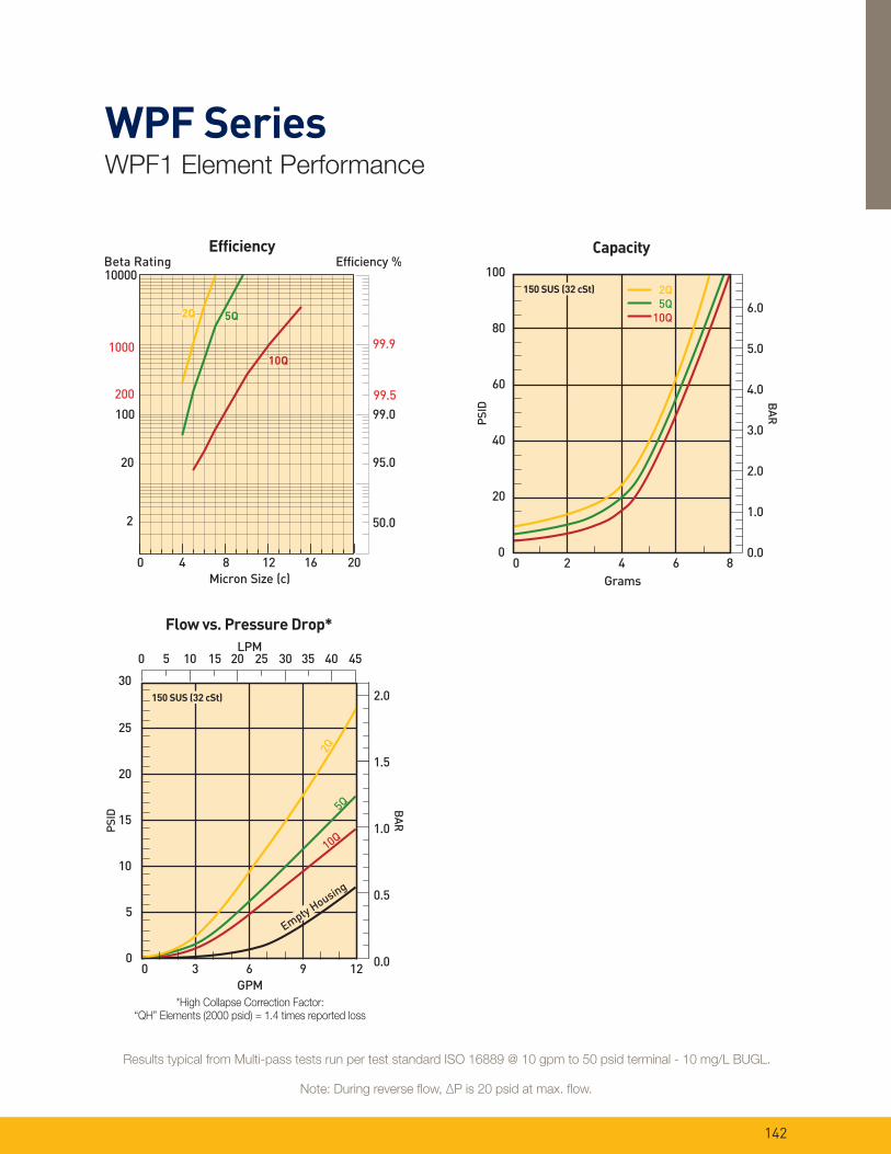
WPF SeriesWPF1 Element Performance
*High Collapse Correction Factor: “QH” Elements (2000 psid) = 1.4 times reported loss
30
1.5
2.0
1.0
0.5
0.0
BA
R
PS
ID
25
20
15
10
5
0
GPM
0 3 6 9 12
0 5 10 15 20 25 30 35 40 45
2Q5Q
10Q
Empty H
ousing
150 SUS (32 cSt)
LPM
Flow vs. Pressure Drop*
100
4.0
6.0
2.0
5.0
3.0
1.0
0.0
BA
R
PS
ID
80
60
40
20
0
Grams
0 2 4 6 8
150 SUS (32 cSt)
Capacity
2Q
5Q
10Q
Note: During reverse flow, ∆P is 20 psid at max. flow.
Results typical from Multi-pass tests run per test standard ISO 16889 @ 10 gpm to 50 psid terminal - 10 mg/L BUGL.
142

*High Collapse Correction Factor: “QH” Elements (2000 psid) = 1.4 times reported loss
Note: During reverse flow, ∆P is 20 psid at max. flow.
Results typical from Multi-pass tests run per test standard ISO 16889 @ 25 gpm to 50 psid terminal - 10 mg/L BUGL.
WPF SeriesWPF2 Element Performance
30
1.5
2.0
1.0
0.5
0.0
BA
R
PS
ID
25
20
15
10
5
0
GPM
LPM
0 10 20 30 40
0 50 100 150
2Q
5Q 10Q
Empty H
ousing
150 SUS (32 cSt)
Flow vs. Pressure Drop*
35
30
1.5
2.0
1.0
0.5
0.0
BA
R
PS
ID
25
20
15
10
5
0
GPM
LPM
0 5 10 15 20 25 30
0 50 100
Em
pty
Hou
sing
150 SUS (32 cSt)
Manifold Pressure Drop
100
4.0
6.0
2.0
5.0
3.0
1.0
0.0
BA
R
PS
ID
80
60
40
20
0
Grams
0 5 10 15 20 25
150 SUS (32 cSt)
Capacity
2Q
5Q
10Q
143

*High Collapse Correction Factor: “QH” Elements (2000 psid) = 1.4 times reported loss
Note: During reverse flow, ∆P is 20 psid at max. flow.
Results typical from Multi-pass tests run per test standard ISO 16889 @ 45 gpm to 50 psid terminal - 10 mg/L BUGL.
WPF SeriesWPF3 Element Performance
30
1.5
2.0
1.0
0.5
0.0
BA
R
PS
ID
25
20
15
10
5
0
GPM
LPM
0 15 30 45 60
2Q5Q
10Q
Empty
Housin
g
150 SUS (32 cSt)
0 50 100 150 200
Flow vs. Pressure Drop*
100
4.0
6.0
2.0
5.0
3.0
1.0
0.0
BA
R
PS
ID
80
60
40
20
0
Grams
0 10 20 30 40
150 SUS (32 cSt)
Capacity
2Q
5Q
10Q
144

30
1.5
2.0
1.0
0.5
0.0
BA
R
PS
ID
25
20
15
10
5
0
GPM
0 30 60 90 120 150
0 100 200 300 400 500
2Q5Q
10Q
Empty
Housin
g
150 SUS (32 cSt)
LPM
Flow vs. Pressure Drop*
*High Collapse Correction Factor: “QH” Elements (2000 psid) = 1.4 times reported loss
Note: During reverse flow, ∆P is 20 psid at max. flow.
Results typical from Multi-pass tests run per test standard ISO 16889 @ 90 gpm to 50 psid terminal - 10 mg/L BUGL.
WPF SeriesWPF4 Element Performance
100
4.0
6.0
2.0
5.0
3.0
1.0
0.0
BA
R
PS
ID
80
60
40
20
0
Grams
0 25 50 75 100 125
Capacity
2Q
5Q
10Q
150 SUS (32 cSt)
35
30
1.5
2.0
1.0
0.5
0.0
BA
R
PS
ID
25
20
15
10
5
0
GPM
LPM
0 30 60 90 120
Em
pty
Hou
sin
g
150 SUS (32 cSt)
Manifold Pressure Drop
0 100 200 300 400
145

*High Collapse Correction Factor: “QH” Elements (2000 psid) = 1.4 times reported loss
Note: During reverse flow, ∆P is 20 psid at max. flow.
Results typical from Multi-pass tests run per test standard ISO 16889 @ 100 gpm to 50 psid terminal - 10 mg/L BUGL.
WPF SeriesWPF5 Element Performance
30
1.5
2.0
1.0
0.5
0.0
BA
R
PS
ID
25
20
15
10
5
0
GPM
0 30 60 90 120 150 180
0 100 200 300 400 500 600 700
2Q
5Q
10Q
Empty H
ousing
150 SUS (32 cSt)
LPM
Flow vs. Pressure Drop*
100
4.0
6.0
2.0
5.0
3.0
1.0
0.0
BA
R
PS
ID
80
60
40
20
0
Grams
0 30 60 90 120 150
Capacity
150 SUS (32 cSt) 2Q
5Q
10Q
35
30
1.5
2.0
1.0
0.5
0.0
BA
R
PS
ID
25
20
15
10
5
0
GPM
LPM
0 30 60 90 120
Em
pty
Hou
sin
g
150 SUS (32 cSt)
Manifold Pressure Drop
0 100 200 300 400
146

WPF SeriesSpecifications
Maximum Allowable Operating
Pressure (MAOP):
7000 psi (483 bar)
Rated Fatigue Pressure:
6000 psi (414 bar)
Design Safety Factor: 3:1
Operating Temperatures:
-15°F (-26°C) to 250°F (135°C)
Element Collapse Rating:
Standard: 300 psi (21 bar)
High Collapse: 2000 psi (138 bar)
INDICATOR PORT IS AT 15° AS
SHOWN ON ALL FILTERS
EXCEPT WPF 1 WHICH IS AT 0°
SAE-8 INDICATOR PORT
PLUGGED AS STANDARD
TORQUE: 40 - 45 N-m (30 - 33 ft-lb)
MOUNTING HOLES (4 PLACES)
WPF 1 & 2: M8 x 1.25 x 12 DEEP
WPF 3,4,5: M10 x 1.5 x 12 DEEP
BOWL TORQUE:WPF 1 : 20 - 30 N-m (15 - 20 ft-lb)WPF 2 & 3 : 35 - 40 N-m (25 - 30 ft-lb)WPF 4 & 5: 80 - 95 N-m (60 - 70 ft-lb)
SAE-6 DRAIN PLUGWPF 1: NOT AVAILABLEWPF 2,3,4,5: STANDARDPLUG TORQUE: 35 - 40 N-m (25 - 30 ft-lb)
WPF 1: 24 (15/16) HEX
WPF 2,3,4,5: 38 (1-1/2) HEX
AELEMENT SERVICE CLEARANCE
THREADS ARE METRICFOR FLANGE PORTS
13 (.512) MIN.
Materials:
Head: SG Iron
Bowl: Steel
Indicator: Stainless Steel
with Plastic Connectors
Weights:
WPF1 9 lbs. (4.1 kg)
WPF2 13 lbs. (5.9 kg)
WPF3 21 lbs. (9.5 kg)
WPF4 45 lbs. (20.4 kg)
WPF5 67 lbs. (30 .4 kg)
T-Port
Drawings are for reference only.
Contact factory for current version.
N (4 PLACES)
PO
R
Q
OS
Flange
Size
N: Thread
& DepthO P Q R S
3/4” .750” .937” .469” 2.000” 1.000” .750”
1” 1.000” 1.093” .546” 2.250” 1.125” 1.000”
1-1/4” 1.250” 1.250” .625” 2.625” 1.312” 1.250”
1-1/2” 1.500” 1.437” .719” 3.125” 1.563” 1.500”
Filter Model A B C D E F G H I J K L M
WPF170
2.76
180
7.09
69.5
2.74
23
.91
15
.59
27
1.06
60
2.36
30
1.18
90
3.54
92
3.62
46
1.81
30
1.18
15
.59
WPF279
3.11
293
11.53
75
2.95
32
1.26
26
1.02
30
1.18
80
3.15
40
1.57
98
3.86
110
4.33
55
2.17
40
1.57
20
.78
WPF388
3.47
345
13.58
93
3.66
40
1.57
29
1.14
35
1.38
90
3.54
55
2.17
120
4.72
126
4.96
63
2.48
45
1.77
27.5
1.08
WPF4100
3.94
445
17.52
128
5.04
49
1.93
39
1.54
48
1.89
120
4.72
50
1.97
160
6.3
163
6.42
81.5
3.21
60
2.36
25
.98
WPF5100
3.94
561
22.09
128
5.04
61
2.40
51
2.01
48
1.89
140
5.51
80
3.15
160
6.30
183
7.20
91.5
3.60
70
2.76
40
4.57
T-Port Dimensions (mm/inch)
147

WPF SeriesSpecifications
SAE-4 VENT PLUGTORQUE: 25 - 28 N-m (18 - 20 ft-lb)
M
P
BOWL TORQUE:WPF 2: 35 - 40 N-m (25 - 30 ft-lb)WPF 4 & 5: 80 - 95 N-m (60 - 70 ft-lb)
INLETWPF 4 & 5:
41.2 (1.622) C'BORE
x 1.96 (.077) DEEP
34 (1.34) THRU
2-127 SIZE O-RING INCLUDED
WPF 2:
28.6 (1.125) C'BORE
x 1.96 (.077) DEEP
22 (.866) THRU
2-119 SIZE O-RING INCLUDED
OUTLETWPF 4 & 5:
41.2 (1.622) C'BORE
x 1.96 (.077) DEEP
34 (1.34) THRU
2-127 SIZE O-RING INCLUDED
WPF 2:
28.6 (1.125) C'BORE
x 1.96 (.077) DEEP
22 (.866) THRU
2-119 SIZE O-RING INCLUDED
ø
ø
ø
ø
ø
ø
ø
ø
SAE-6 DRAIN PLUGPLUG TORQUE: 35 - 40 N-m (25 - 30 ft-lb)
HEX: 38 (1-1/2)
D
EF
AELEMENT SERVICE CLEARANCE
SAE-8 INDICATOR PORTPLUGGED AS STANDARDTORQUE: 40 - 45 N-m (30 - 33 ft-lb)
B
H
I
O
N
C
J
L
K
G
13 (.512) MIN.
ManifoldMaximum Allowable Operating
Pressure (MAOP):
7000 psi (483 bar)
Rated Fatigue Pressure:
6000 psi (414 bar)
Design Safety Factor: 3:1
Operating Temperatures:
-15°F (-26°C) to 250°F (135°C)
Element Collapse Rating:
Standard: 300 psi (21 bar)
High Collapse: 2000 psi (138 bar)
Materials:
Head: SG Iron
Bowl: Steel
Indicator: Stainless Steel
with Plastic Connectors
Weights:
WPF2 18 lbs. (8.2 kg)
WPF4 63 lbs. (28.6 kg)
WPF5 70 lbs. (31.7 kg)
Drawings are for reference only.
Contact factory for current version.
Filter Model A B C D E F G H I J K L M N O P
WPF279
3.11
343
13.50
75
2.95
24
.94
39
1.53
95
3.74
116
4.57
50
1.97
6
.24
110
4.33
80
3.15
40
1.57
110
4.33
121
4.76
17
.67
30
1.18
WPF4100
3.94
532
20.94
128
5.04
38
1.50
57
2.24
140
5.51
150
5.91
75
2.95
13
.51
142
5.59
100
3.94
50
1.97
166.5
6.56
161
6.34
21
.83
31.7
1.25
WPF5100
3.94
627
24.69
128
5.04
38
1.50
57
2.24
140
5.51
150
5.91
75
2.95
13
.51
142
5.59
100
3.94
50
1.97
166.5
6.56
161
6.34
21
.83
31.7
1.25
Manifold Dimensions (mm/inch)
148

WPF SeriesIndicator Specifications
B
E2
A
2
1
3
B
M2 E2
Torque: 30-33 ft-lb (40-45 N-m)
Indicator setting: 50 psid
Option Description Connection/Power Wiring “A”
M2 Visual auto reset N/A N/A N/A
WPF5 Electrical/visual
DIN 43650 3 pole +Earth
5A@125/250 VAC,
3A@28VDC
Pin 1 - Common
Pin 2 - Normally closed
Pin 3 - Normally open
73.7
2.90
Indicator Dimensions (mm/inch)
149

1 Stop system power and vent captive pressure.
2 Drain filter assembly.
3 Remove bowl and element assembly.
4 Push down to squeeze tangs and lift element.
5 Twist to remove core.
6 Retain reusable core.
7 Discard used element.
8 Insert reusable core into new element until it snaps.
9 Push element assembly into bowl, snap tangs.
10 Inspect o-ring and anti-extrusion ring.
11 Install bowl with new element.
12 Torque bowl, vent and drain plugs.
13 Power up and inspect.
WPF SeriesService & Maintenance Instructions
4 5
6 8
9 11
150

WPF SeriesParts List
8 9 10
11
1
2
3
4
5
6
7
Index Part Description Part Number
1 WPF1 Head SAE-8 940986
WPF2 Head 3/4” Flange 940989
WPF2 Head SAE-12 940988
WPF3 Head 1” Flange 940992
WPF3 Head SAE-16 940991
WPF4 Head 1-1/4” Flange 940923
WPF4 Head SAE-20 940924
WPF5 Head 1-1/2” Flange 940773
WPF5 Head SAE-24 940921
2 Element See chart on page 153
3 WPF1 Reusable Core 941175
WPF2 Reusable Core 941176
WPF3 Reusable Core 941177
WPF4 Reusable Core 941178
WPF5 Reusable Core 941179
4 WPF1 Bowl O-ring V92141
WPF2 Bowl O-ring V92144
WPF3 Bowl O-ring V92042
WPF4 Bowl O-ring V92157
WPF5 Bowl O-ring V92157
5 WPF1 Anti-extrusion Ring 941185
WPF2 Anti-extrusion Ring 934798
WPF3 Anti-extrusion Ring 941186
WPF4 Anti-extrusion Ring 941187
WPF5 Anti-extrusion Ring 941187
6 WPF1 Bowl 942296
WPF2 Bowl 942299
WPF3 Bowl 942300
WPF4 Bowl 941156
WPF5 Bowl 941157
7 Drain Plug 934320
8 Indicator Plug 941172
9 Electrical Indicator 941173
11 Name Plate 920928
Not
Shown
Drive Screw (2 required) 900028
T-port
151

WPF SeriesParts List
1 12112
3
4
5
6
7
8
109Index Part Description Part Number
1 WPF2 Manifold Mount Head 941273
WPF4 Manifold Mount Head 940982
WPF5 Manifold Mount Head 940982
2 WPF2 Manifold Mount O-rings (2 req’d) V92119
WPF4 Manifold Mount O-rings (2 req’d) V92127
WPF5 Manifold Mount O-rings (2 req’d) V92127
3 Element See chart on page 153
4 WPF2 Reusable Core 941176
WPF4 Reusable Core 941178
WPF5 Reusable Core 941179
5 WPF2 Bowl O-ring V92144
WPF4 Bowl O-ring V92157
WPF5 Bowl O-ring V92157
6 WPF2 Anti-extrusion Ring 934798
WPF4 Anti-extrusion Ring 941187
WPF5 Anti-extrusion Ring 941187
7 WPF2 Bowl 941154
WPF4 Bowl 941156
WPF5 Bowl 941157
8 Drain Plug 934320
9 Vent Plug 928882
10 WPF Indicator Plug 941172
11 Electrical Indicator 941173
12 Visual Indicator 941174
Not
Shown
Name Plate 920928
Not
Shown
Drive Screw (2 required) 900028
Manifold
152

BOX 1 BOX 2 BOX 3 BOX 4 BOX 5 BOX 6 BOX 7 BOX 8
WPF 2 10QE V M2 K S12 1
BOX 1: Filter Series
Symbol Description
WPF High Pressure Filter
BOX 2: Element Length
Symbol Description
1 1/2” Nominal ports
2 3/4” Nominal ports
3 1” Nominal ports
4 1 1/4” Nominal ports
5 1 1/2” Nominal ports
BOX 3: Media Code
Symbol Description
Standard Element (bypass only)
02QE Microglass, 2 micron
05QE Microglass, 5 micron
10QE Microglass, 10 micron
High Collapse (no-bypass only)
02QH Microglass, 2 micron
10QH Microglass, 10 micron
WPF SeriesHigh Pressure Duplex Filters
How To OrderSelect the desired symbol (in the correct position) to construct a model code.
Example:
BOX 4: Seals
Symbol Description
B Nitrile
E Ethylene Propylene
V Fluorocarbon
BOX 5: Indicators
Symbol Description
P Plugged indicator port
M2 Visual automatic reset
E2Electrical/Visual (DIN 43650
style connection)
Note: When the “M2” or “E2” option is selected, the indicator port is plugged and the indicator is shipped as a loose part.
BOX 6: Bypass & Indicator Setting
Symbol Description
K 50 psid (3.5 bar)
XNo bypass & No indicator
(port plugged)
Note: When an indicator and no bypass (“2” in Box 8) is selected, the indicator setting is 50 psid (3.5 bar).
BOX 7: Ports
Symbol Description
WPF1
S08 SAE-8
WPF2
S12 SAE-12
Y12 3/4” SAE code 62 flange face
X12 Manifold
WPF3
S16 SAE-16
Y16 1” SAE code 62 flange face
WPF4
S20 SAE-20
Y201 1/4” SAE code 62 flange
face
X20 Manifold
WPF5
S24 SAE-24
Y241 1/2” SAE code 62 flange
face
X24 Manifold
BOX 8: Options
Symbol Description
1 Bypass (standard element only)
2No bypass (high collapse
element only)
Replacement Elements
Media WPF1 WPF2 WPF3 WPF4 WPF5
Standard Collapse
300 psid (21 bar)
Microglass, 02QE 941029Q 941032Q 941035Q 941038Q 941041Q
Microglass, 05QE 941030Q 941033Q 941036Q 941039Q 941042Q
Microglass, 10QE 941031Q 941034Q 941037Q 941040Q 941043Q
High Collapse
2000 psid (138 bar)
Microglass, 02QH 941044Q 941046Q 941048Q 941050Q 941052Q
Microglass, 10QH 941045Q 941047Q 941049Q 941051Q 941053Q
Please note the bolded options reflect
standard options with a reduced lead time.
153