Embed Size (px)
Citation preview
1
21st September 2021
World Robot Summit 2020
Disaster Robotics Category: Plant Disaster Prevention Challenge
Competition Rules Ver. 1.53
・ These rules are subject to change.
・ Please visit http://worldrobotsummit.org/ for the latest version of the rules.
・ If any discrepancies are found between the different language versions of the
rulebooks, the English version will take precedence.
2
Table of Contents
1. Competition Scenario and Background 4
2. Competition Field 7
3. Competition Missions 8
Mission P1: Inspection and Maintenance 9
Mission P2: Fault Detection and Emergency Response 12
Mission P3: Diagnosis: Pipes and Duct 15
Mission P4: Diagnose: Tank 18
Mission P5: Accident Response: Search 21
4. Targets of Inspection 22
4.1 Outline of Facilities/Structures 22
4.1.1 Pipes: 1st Floor (both a/b) 22
4.1.2 Pump: 1st Floor (both a/b) 23
4.1.3 Small Tank: 1st Floor (both a/b) 24
4.1.4 Boiler: 1st Floor (both a/b) 24
4.1.5 Pipes (C): 2nd Floor 26
4.1.6 Duct: 2nd Floor 27
4.1.8 Large Tank: 3rd Floor 28
4.2 Outline of targets to inspect/adjust 29
4.2.1 Pressure Gauge 29
4.2.2 Thermometer 29
4.2.3 Water Level Meter 29
4.2.4 Valves 30
4.3 Abnormalities 31
4.4 Road Surface Types 31
4.5 Rubble 31
5. Competition Schedule 32
6. Scoring 32
6.1 Mission Points: Assessing the Mission’s Level of Achievement 32
3
6.2 Technical Points: Assessing the Robot’s Technical Level 32
6.3 Time Points: Assessing the time taken to complete missions 33
6.4 Terms for Tallying Points and Determining a Winner 33
7. Team Members 33
8. Competition robots 33
9. Missions 35
10. Communication Network 36
11. Awards 36
12. Miscellaneous 36
4
1. Competition Scenario and Background
The concept of this competition is to reproduce the routine inspections/checks that occur in aging
and deteriorating manufacturing plants, oil refineries, and iron works. This includes the response to
emergency situations. Competition tasks and missions dealing with various types of plant have been
set up.
The advantages of the introduction of robots into plant inspections
[Autonomous Routine Inspections] Accidents caused by human error can be avoided through
autonomous inspections and diagnosis of facilities (pumps, tanks, boilers) and structures in
dangerous environments such as off-shore plants, where it can be difficult to dispatch workers. In
addition, labor costs can be saved by eliminating the need to archive inspection results and set up
scaffolding.
[Early Detection of Abnormalities (deterioration)] Introducing robots would increase the frequency of
routine inspections, preventing human errors and deterioration from damaging facilities, which in turn
can cause equipment malfunctions, accidents (explosions from gas leaks or fires caused by toxic
gas), or toxic substance leaks.
In order to carry out inspections and checks of facilities that operate under high temperatures or in
dangerous conditions, they need to be turned off. By using robots in these kinds of conditions, checks
could be carried out while plants are in operation, thereby increasing the plant’s productivity.
[Emergency Response] A part of a pipe could become damaged from age or deterioration, then
resulting in a leak of flammable gas that could cause an accident (such as an explosion or fire). In
this situation a robot would be able to both shut off the pipe that is emitting flammable gas, and turn
on the sprinkler and firefighting system in the room affected by the leak, thus ensuring the safety of
the workers and containing the accident.
References:
SPRINT Robotics Strategic Roadmap for Inspection and Maintenance Robotics
https://www.sprintrobotics.org/media-downloads/sprint-robotics-strategic-roadmap/
5
Reference: The advantages of introducing robots
(1) Safety Improvements
Improves the safety of inspection workers.
(2) Environmental Performance Improvements
Avoids leaks of toxic substances, and explosions.
(3) Cost Avoidance and Reduction
Reduces time consuming tasks such as cleaning and setting up scaffolding.
(4) Performance Improvements
Decreases shutdown time, and increases the frequency and quality (objectivity) of inspections.
Reference: Abilities required for plant inspection robots
(1) Ability to patrol the plant and return to start area via remote or autonomous control.
(2) Ability to traverse high places, narrow or confined spaces, and ascend/descend stairs.
(3) Ability to detect abnormalities/faulty equipment and diagnose the structural health through
nondestructive inspection (as opposed to methods such as visual inspections and hammering
test).
(4) Ability to adjust the operational status of equipment (adjusting valves, pressing switches etc.).
(5) Ability to digitalise and archive inspection results, and rapidly create reports.
(6) Ability to adapt to restrictive environments (smoke/steam, dirt, rubble).
Reference: Definition of autonomous/automatic control
・Automatic Meter Reading: Necessary
Robot has the technology to input unprocessed data from cameras and sensors and output
numerical values and enter them into a report, without human intervention. Humans may
intervene when triggering the data acquisition.
・Automatic Evaluation and Diagnosis: Necessary
Robot has the technology to input unprocessed data from cameras and sensors and output
as numerical values the results of the evaluation and diagnosis of the structural health, without
human intervention.
・Autonomous Navigation:
Robot has the technology to understand the environment, safely patrol and inspect/operate
the specified equipment, and return without detailed instruction from humans.
・Autonomous Manipulation:
Robot has the technology to recognise the shape of objects to be grasped, automatically
control the grasp torque and rotate the handle/lever, or remove debris, without detailed
instruction from humans.
・Automatic Recognition/Detection:
6
Robot has the technology to recognise the target for inspection/operation and identify the
position without human intervention.
・Measurement, Evaluation and Diagnostic Device Integration:
Robot has integrated technology with built-in sensors to quantify (digitalise) the operating status
of equipment and structural health, and to automate the detection of faults/anomalies (Fault
Anomaly Detection), evaluate and diagnose.
7
2. Competition Field
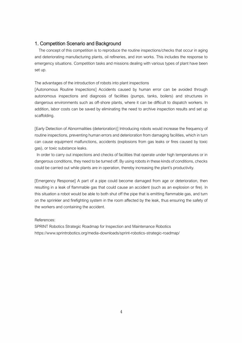
The competition field consists of a 6-storey mock plant tower built as a reproduction of a working
plant at Fukushima Robot Test Field, in Fukushima Pref. Minami Souma city. Each floor is 5m in height
and is organised in the following way.
1st Floor: Basic facilities (pumps, boilers, small tanks, pipes), 2nd Floor: Pipes, 3rd/4th Floors: medium
and large tanks, 5th/6th Floors: Chimney. The competition field will be from the 1st to 3rd floors.
Figure 1: Mock plant tower at Fukushima Robot Test Field
Each task will be carried out on the facilities and equipment within the mission zones of each floor
of the Fukushima Robot Test Field, according to the inspection instructions. The operation area, where
the robot operation and controls are carried out, will be on the 1st floor outside the plant tower. All
missions will be carried out from this operation area.
Mission zones:
P1: 1st Floor (a) *. Target area - pipes (A), pump x 3, tank (small) x 2
P2: 1st Floor (b) *. Target area – pipes (B), pump x 3, boiler
P3: 2nd Floor. Target area – pipes (C), Duct
P4: 3rd Floor. Target area – Tank (Large)
P5: 1st Floor (a)(b). Target area – pipes (A), pump x 3, tank (small) x 2, boiler
*1st Floor (a) is on the east side, 1st Floor (b) is on the west side.
8
3. Competition Missions
5 missions have been set up in order to assess the plant inspection robot’s abilities.
P1: Inspection and Maintenance
P2: Fault Detection and Emergency Response
P3: Diagnosis: Pipes and Duct
P4: Diagnosis: Tank
P5: Accident Response: Search
Each mission consists of a series of tasks (inspections, surveys, etc.) to be carried out according to
the inspection instructions. Each mission takes place in a specified zone (mission zone), whereby the
robot must start from the ‘start area’ and move through each waypoint as it completes each task.
Once all tasks have been completed, the robot must return to the ‘start area’. In mission P5, the robot
must pass through ‘checkpoint areas’, where the points gained in the mission thus far will be added
to their total score. The order in which tasks are completed is up to the team’s discretion.
Within 10 minutes of completing the mission, enter the inspection/work data into the specified report
(electronic file), and submit together with digital data such as images and measured values. Details
of the submission method will be given separately.
The positions after the qualifying round will be decided based on the total competition points earnt
in each mission. Competition points are the sum of the mission points, technical points, and time
points. Details concerning points can be found in chapter 6. If the mission is carried out autonomously,
operator intervention is allowed at the start of each stage of ‘movement’, ‘inspection (operation)’, and
‘report’.
Below are the details of each mission and its tasks. Point distribution will be detailed separately in
the inspection instructions.
9
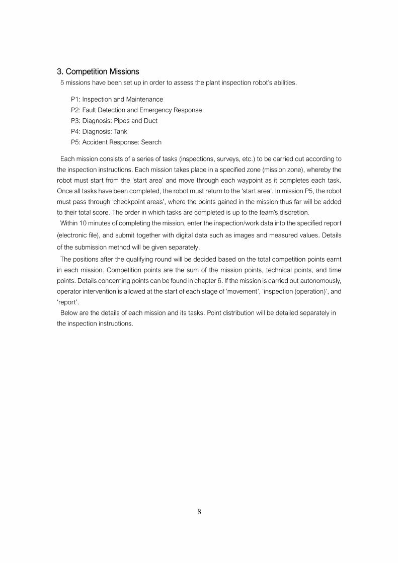
Mission P1: Inspection and Maintenance
Competition Mission:
Routine inspections of plants are carried out several times a day by
a number of employees. The objective of this mission is to save
labour by performing these inspections using remotely controlled or
autonomous robots. In mission P1, the robot should carry out daily
inspections and surveys of the facilities.
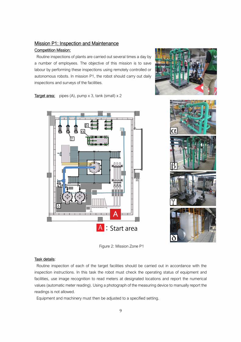
Target area: pipes (A), pump x 3, tank (small) x 2
Figure 2: Mission Zone P1
Task details:
Routine inspection of each of the target facilities should be carried out in accordance with the
inspection instructions. In this task the robot must check the operating status of equipment and
facilities, use image recognition to read meters at designated locations and report the numerical
values (automatic meter reading). Using a photograph of the measuring device to manually report the
readings is not allowed.
Equipment and machinery must then be adjusted to a specified setting.
10
Pipes (A)
(1) Confirm the Pressure Gauge Reading
Take readings of the pressure gauges placed in horizontal and vertical positions, check if these
readings match those indicated in the inspection instructions, and report findings. After
completing the mission, submit the processed images of the meters used to confirm the readings.
(2) Open and Close Valves
Adjust the handles of both horizontally and vertically placed valves to positions specified in the
inspection instructions.
(3) Adjust Valves
Turn the handles of both horizontally and vertically placed valves to angles specified in the
inspection instructions.
Pump x 3
(1) Confirm Operation
Check the LED control panel and report which pumps are in operation.
(2) Confirm the Pressure Gauge Reading
Take readings of the pressure gauge, check if these readings match those indicated in the
inspection instructions, and report findings. After completing the mission, submit the processed
images of the meters used to confirm the readings.
(3) Open and Close Valves
Close (turn 90 degrees) the valves of the pumps not in operation.
Tank (small) x 2
(1) Confirm Water Level Reading
Read the water level meters, check if these readings match those indicated in the inspection
instructions, and report findings. After completing the mission, submit processed images of the
meters used to confirm the readings.
(2) Open and Close Valves
Adjust the valves as indicated in the inspection instructions.
Required Abilities:
[Mobility] The areas that must be traversed are walkways (600mm wide at narrowest point), slopes,
and groups of pipes. The surfaces consist of concrete, grating, and checker plate. The robot must be
able to move around this area (walkways 600mm wide, steps 130mm high).
[Monitoring and Operation] The targets to inspect and adjust are meters and valves of a pre-disclosed
shape and position. The robot must be able to inspect and adjust these targets through the use of its
sensors and manipulators (read pressure gauges and water levels, operate valves).
[Adapting to the Environment] Robots must have the ability to adapt to an everyday plant environment
comprising of various machines and equipment surrounded by a maze of pipes. In addition, they must
have the ability to deal with weather such as wind and rain, and the ability to deal with fogged or dirty
glass on the faces of the meters.
11
Technical Challenges
Along with performing automatic meter readings, the robot should able to operate the valve as
feedback in response to changes in the reading values. Additionally, they need to have a practical
level of processing power (speed and accuracy), and the ability to perform autonomous checks.
Examples of how to gain technical points:
[Mobility] Based on the inspection instructions, move autonomously using self-localization etc.
[Inspection (meters)] Automatically recognise the position of the targets to inspect (pressure gauge,
water level meter, the pump’s LED control panel) through image processing. Then, by autonomous
control of the robot and manipulator, automatically recognise the meter’s dial, and display the
numerical readings on a PC monitor.
[Adjustments (handle/lever operation)] Automatically recognise the handle or lever’s position, and
grasp the handle or valve with the autonomous manipulator’s attitude control and end effectors
handling system, and make the appropriate turn.
[Report] n/a
12
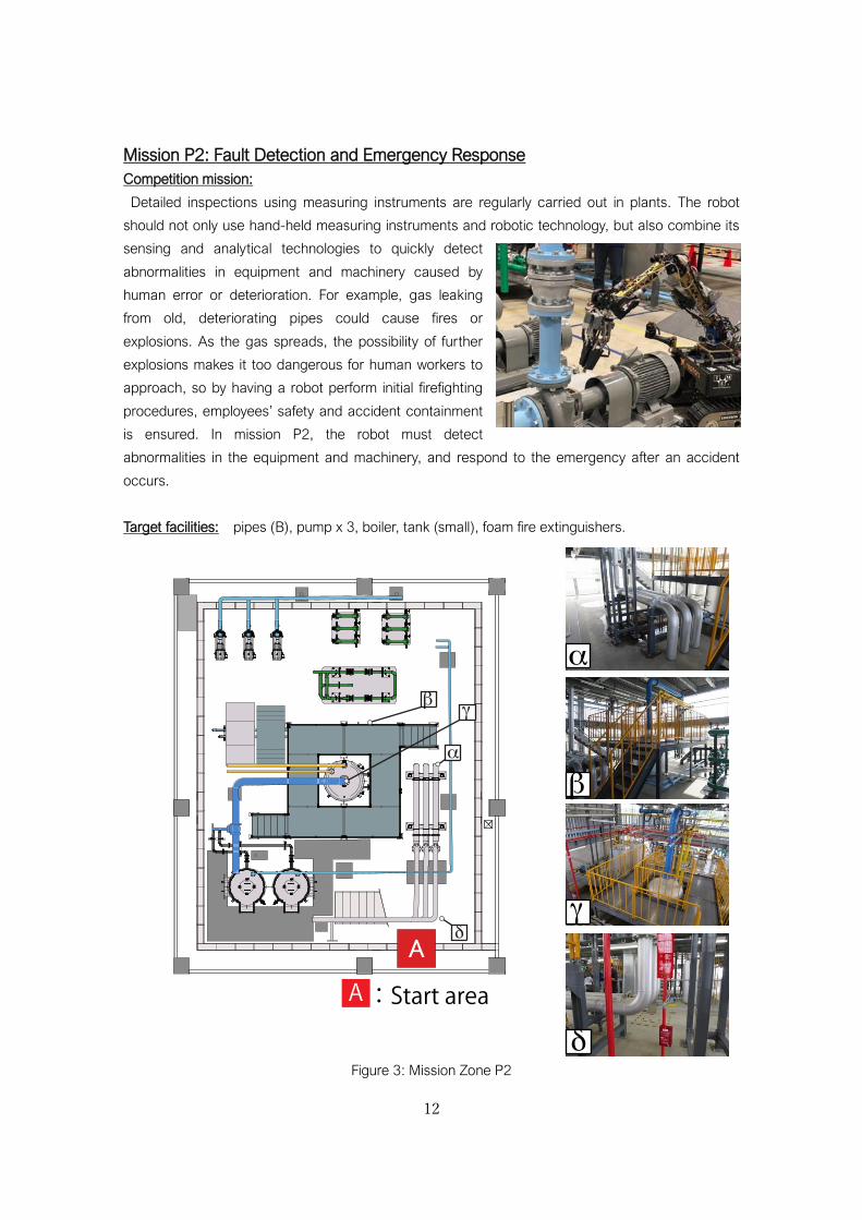
Mission P2: Fault Detection and Emergency Response
Competition mission:
Detailed inspections using measuring instruments are regularly carried out in plants. The robot
should not only use hand-held measuring instruments and robotic technology, but also combine its
sensing and analytical technologies to quickly detect
abnormalities in equipment and machinery caused by
human error or deterioration. For example, gas leaking
from old, deteriorating pipes could cause fires or
explosions. As the gas spreads, the possibility of further
explosions makes it too dangerous for human workers to
approach, so by having a robot perform initial firefighting
procedures, employees’ safety and accident containment
is ensured. In mission P2, the robot must detect
abnormalities in the equipment and machinery, and respond to the emergency after an accident
occurs.
Target facilities: pipes (B), pump x 3, boiler, tank (small), foam fire extinguishers.
Figure 3: Mission Zone P2
A
13
Task details:
Perform routine inspections and detect abnormalities in each of the target facilities in accordance
with the inspection instructions. After an accident occurs, carry out initial firefighting procedures. The
task consists of discovering gas leaks or abnormal temperatures in the pipes, specifying which pumps
are emitting abnormal vibrations, and measuring the concentration of oxygen in the tank. After the
alarm sounds, the robot must operate a handle to manually turn on the foam fire extinguisher. Using
a photograph of the measuring device to manually report the readings is not allowed.
Pipes (B)
(1) Detect abnormal temperatures on the pipes’ surface.
Report the location and difference in temperature
Pump x 3
(1) Specify which pump has abnormalities.
Check the status of each pump and report any abnormalities.
Tank (small) x 2
(1) Measure the concentration level of oxygen inside the tank.
Report the oxygen concentration reading
Boiler
Lower Inspection Walkway (confined space):
(1) Confirm the pressure gauge reading
Take a reading of the pressure gauges in designated locations, confirm the pressure is set to the
amount specified in the inspection instructions, and report. After completing the mission, submit
processed images of the meters used to confirm the readings
(2) Open and close valves
Adjust the valves of the pressure gauges with values that differ to those indicated in the
inspection instructions so that they show that the indicated amount
Upper Inspection Walkway (access via stairs):
(3) Pressure gauge reading and close valve
Take a reading of the pressure gauge and close (turn 90 degrees) the valve as indicated in the
inspection instructions. Submit the processed images of the gauges used to confirm the readings.
After the alarm sounds:
(5) Activate the foam fire extinguishers near the walkway. (turn the handle 90 degrees).
Required Abilities:
[Mobility] The same abilities as mission P1, plus the ability to traverse a walkway. (Space restrictions:
confined (600mm wide), climbing stairs (40° gradient)).
14
[Monitoring and Operation] Inspect for abnormal temperatures, abnormal vibrations, etc. As well as
the inspection and operation abilities required in Mission P1, the robot should also be able to detect
abnormalities using its sensors and cameras (abnormal temperatures or pumps, oxygen
concentration in the tank). The location of the abnormalities will be unknown.
You may use your own measuring instruments, or those provided by the competition organisers.
However, measuring instruments/probes must be mounted on the robot before the mission begins.
Measuring instruments/probes cannot be removed from the robot during the mission.
※Measuring instruments provided: Vibrometer VM-82A (RION), Sound level meter NL-42 (RION)
[Report] The ability to specify and report the location of abnormalities is required.
[Adapting to the Environment] The same abilities are required as Mission P1.
Technical Challenges
(1) Along with the ability to automatically recognise meter readings (automatic meter reading), the
robot should able to operate the valve as feedback in response to changes in the reading values.
Additionally, it needs a practical level of processing power (speed and accuracy), and the ability to
perform autonomous checks.
(2) Detect abnormalities without prior knowledge of their location. The ability to implement existing
measuring instruments along with the robot’s own measuring equipment (integration technology) is
necessary.
(3) The goal is to implement comprehensive, practical abilities, particularly tasks in a noisy, unknown
environment, as well as to be able to apply these routine inspection abilities to emergency response
after an accident occurs.
Examples of how to gain technical points:
[Mobility] Based on the inspection instructions, move autonomously using self-localization etc.
[Inspection (meters)] Automatically recognise the position of the targets to inspect (pressure gauge,
water level gauge, the pump’s LED control panel) through image processing. Then, by autonomous
attitude control of itself and its manipulator, the robot automatically recognises the meter’s dial and
displays the numerical readings on a PC monitor.
[Adjustments (operating handle/lever)] Can automatically recognise the handle and lever’s position,
can grasp it with the autonomous manipulator’s attitude control and end effectors handling system
(autonomous control), while making the appropriate turn.
[Report] Can digitalise the numerical value of gas concentrations and pump vibrations RMS/sound
pressure, and submit a report.
15
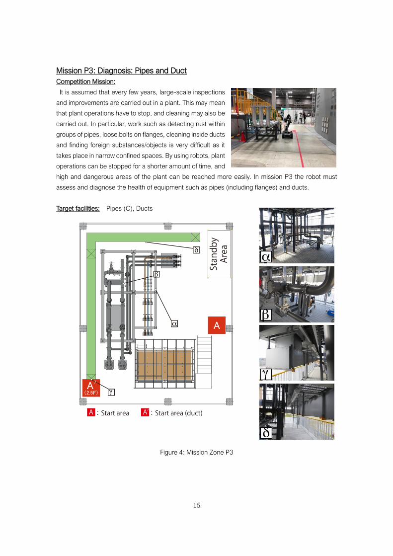
Mission P3: Diagnosis: Pipes and Duct
Competition Mission:
It is assumed that every few years, large-scale inspections
and improvements are carried out in a plant. This may mean
that plant operations have to stop, and cleaning may also be
carried out. In particular, work such as detecting rust within
groups of pipes, loose bolts on flanges, cleaning inside ducts
and finding foreign substances/objects is very difficult as it
takes place in narrow confined spaces. By using robots, plant
operations can be stopped for a shorter amount of time, and
high and dangerous areas of the plant can be reached more easily. In mission P3 the robot must
assess and diagnose the health of equipment such as pipes (including flanges) and ducts.
Target facilities: Pipes (C), Ducts
Figure 4: Mission Zone P3
16
Task details:
Assess and diagnose the soundness of pipes and the inside of the duct in accordance with the
inspection instructions. For the mission tasks, the robot must report the assessment results for the
following targets in each of the inspection areas. If automatic evaluation and diagnosis is carried out,
the processed images that were used to assess the abnormalities must be submitted.
Pipes (C)
(1) Discover loose bolts on the flanges.
Report which bolts are loose or not
(2) Detect bolts with rust on the flanges.
Report whether the bolt has rust or not
(3) Detect rust (as a QR code) on the surface of the pipes.
Report if there is rust or not
Inside the Duct
(4) Detect the presence of rust (rust, QR marker).
(5) Detect foreign object(s) (location and photograph) (submit after completing the mission).
Points for tasks (4) and (5) will only be added once the robot has returned to the start area A’.
※The team safety manager and/or assistants are allowed to bring the robot to the duct entrance,
and to pick up the robot from the other side.
Required Abilities:
[Mobility] Must be able to move through narrow spaces such as around groups of pipes (restricted
space) and inside a duct (narrow, confined space). (600mm wide (500mm at one place) walkway,
see subsection 4.1.6 Duct for entry into and through the duct.)
[Monitoring and Operation] The target areas to diagnose are pipes and a duct. Robots need the ability
to evaluate and diagnose, using their sensors and cameras to detect abnormalities in the pipes
(surface rust, loose/rusty bolts) and in the duct (rust). The location of abnormalities will not be made
known.
[Report] Must be able to specify and report the location of the abnormalities and foreign objects.
[Adapting to the Environment] The same abilities are required as Mission P1.
Technical Challenge:
Inspect a complex group of pipes and the confined space inside a duct. It is not essential for the
robot to have integration technology and/or autonomous control and automatic recognition, but it
does need a high level of human to robot interactivity to deal with the complex, narrow spaces, as
well as data analysis processing power. A practical level of processing power (speed and accuracy)
is required. When making a report, the ability to create a 3D model in real time and map the results
of the inspection is required to identify the areas to inspect.
17
Examples of how to gain technical points:
[Mobility] Set several waypoints and autonomously traverse the area.
[Inspection (bolt)] Automatically recognise the position of the bolt through image processing etc. The
end effector is able to face the bolt head through autonomous attitude control (autonomous control)
of the robot body and manipulator.
[Inspection (diagnosis)] The robot can autonomously point a camera directly at the area using a
manipulator and automatically recognise and analyse each abnormality (rust, foreign object, etc.)
[Report] Can report the numerical value of the bolt’s tension/torque. Can create a 3D map in real
time, and indicate the positions of the abnormalities on the map.
18
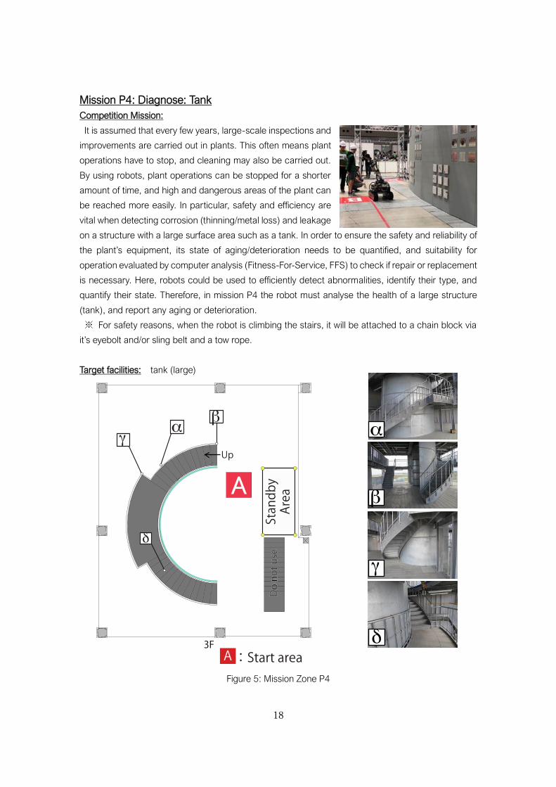
Mission P4: Diagnose: Tank
Competition Mission:
It is assumed that every few years, large-scale inspections and
improvements are carried out in plants. This often means plant
operations have to stop, and cleaning may also be carried out.
By using robots, plant operations can be stopped for a shorter
amount of time, and high and dangerous areas of the plant can
be reached more easily. In particular, safety and efficiency are
vital when detecting corrosion (thinning/metal loss) and leakage
on a structure with a large surface area such as a tank. In order to ensure the safety and reliability of
the plant’s equipment, its state of aging/deterioration needs to be quantified, and suitability for
operation evaluated by computer analysis (Fitness-For-Service, FFS) to check if repair or replacement
is necessary. Here, robots could be used to efficiently detect abnormalities, identify their type, and
quantify their state. Therefore, in mission P4 the robot must analyse the health of a large structure
(tank), and report any aging or deterioration.
※ For safety reasons, when the robot is climbing the stairs, it will be attached to a chain block via
it’s eyebolt and/or sling belt and a tow rope.
Target facilities: tank (large)
Figure 5: Mission Zone P4
19
Task details:
Analyse and diagnose the health a large tank’s surface and its spiral staircase in accordance with
the inspection instructions. Quantify each abnormality through image analysis (automatic evaluation
and diagnosis). For each inspection area (4 test piece boards), report the coordinates of the target
area, and the evaluation and diagnosis results for the following abnormalities.
(1) Presence of cracks.
Report the length and width of the crack through image processing etc. Submit these processed
images after completing the task.
(2) Presence of rust
Report the area ratio and distribution type of rust in the test piece area. Submit these processed
images after completing the task. [reference: ASTM D610]
(3) Presence of metal loss
Measure the thickness of the area with metal loss using an ultrasonic thickness gauge. Submit
an image of the measuring device’s numerical display after completing the task.
Required Abilities:
[Mobility] Requires the ability to traverse high places and (spiral) stairs.
[Monitoring and Operation] The target area for diagnosis is a large tank. In order to evaluate and
diagnose the health of the tank wall surface, the robot needs to efficiently inspect a wide area (range:
9m wide, 5m high). The location of the abnormalities is unknown. Please refer to the document “How
to Reproduce Deterioration” for details of the abnormalities.
For metal loss, use a handheld measuring device (ultrasonic thickness gauge): 27MG (Olympus
Ultrasonic Transducer: D799)) to measure the thickness of the relevant test piece board, and report
the minimum thickness of each test piece. Measuring devices and transducers must be mounted on
the robot before the competition starts. Measuring instruments/probes cannot be removed from the
robot during the mission.
[Report] Use mounted sensors, cameras etc. to quantify the coordinates of the abnormality’s location
(area), type of abnormality, and its state (crack width/length, rust distribution) on the tank wall surface.
[Adapting to the Environment] The same abilities are required as Mission P1.
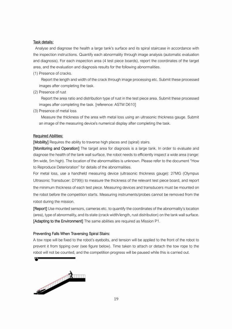
Preventing Falls When Traversing Spiral Stairs:
A tow rope will be fixed to the robot’s eyebolts, and tension will be applied to the front of the robot to
prevent it from tipping over (see figure below). Time taken to attach or detach the tow rope to the
robot will not be counted, and the competition progress will be paused while this is carried out.
20
Technical Challenges:
Survey a wide surface area such as a large tank. The robot does not need to have integration
technology or autonomous control, but it does need a high level of human to robot interactivity to deal
with the complex wide areas, as well as having data analysis processing power. A practical level of
processing power (speed and accuracy) is required. When making a report, the ability to create a 3D
model in real time and map the results of the inspection is required to identify the areas to inspect.
Examples of how to gain technical points:
[Mobility] Set several waypoints and autonomously traverse the area.
[Inspection (operation)] Wipe off the penetrant on the crack test piece.
[Inspection (diagnosis)] Can autonomously point a camera directly at the area using a manipulator,
and automatically recognise each abnormality’s state and location.
[Report] Create a real-time 3D map, and show the abnormality’s position and diagnosis result.
21
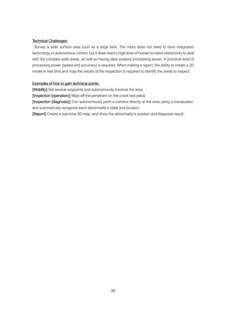
Mission P5: Accident Response: Search
Competition Mission:
An accident (explosion) occurs during a round of inspections, and a roll
call reveals that one employee is missing. Mission P5 is a comprehensive
competition task, as the robot must perform a routine inspection, as well
as respond to an emergency and find a missing person.
Target facilities: pipes (A), pump x 3, tank (small) x 2, boiler
Figure 6: Mission Zone P5 (B-H: Check point areas)
Task details and points:
The routine inspection tasks will be based on P1/P2. After an alarm sounds, the robot should remove
scattered rubble from its path, and then search for employees (mannequins) left inside the plant and
report their position. Other details of the reports and submission will be in the inspection instructions.
Required Abilities:
[Mobility] Requires the ability to traverse areas covered in rubble.
[Monitoring and Operation] Requires ability to remove rubble and search for a missing employee.
[Adapting to the Environment] Requires the same abilities as in P1 to adapt to the surroundings. It is
also necessary to be able to adapt to disaster environments (unstructured environment such as
smoke, water, oil, rubble, etc. with little information in advance.)
Technical Challenges:
Comprehensive and practical abilities are required. In particular, the ability to operate in an unknown
environment with external interference. The robot should be able to adapt its abilities for the mission
tasks to an emergency situation.
22
4. Targets of Inspection
4.1 Outline of Facilities/Structures
4.1.1 Pipes: 1st Floor (both a/b)
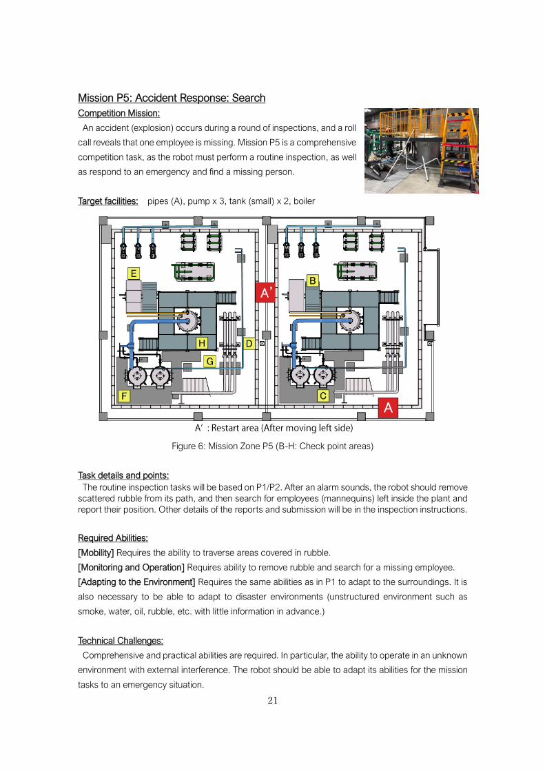
4.1.1.1 Pipes (A)
⚫ Horizontal pipes
Specifications:
・JIS-SGP Pipe (80A), JIS-SS (10K) flange, JIS-SS
Welded elbow (bend)
・Pressure gauge, ball valve (80A), gate valve
(80A), rubber seated valve (80A)
Points to inspect:
(1) Pressure gauge measurements (P1, P5): 3 range types 0.25, 1.0, 1.6 MPa. Reading accuracy
within ±5%. The gauges will be installed between heights of approx. 600mm to 1800mm.
(2) Open and close valves (P1, P5): Levers (Approx. 400mm in length) and round handles.
Content of the report (criteria):
・n/a
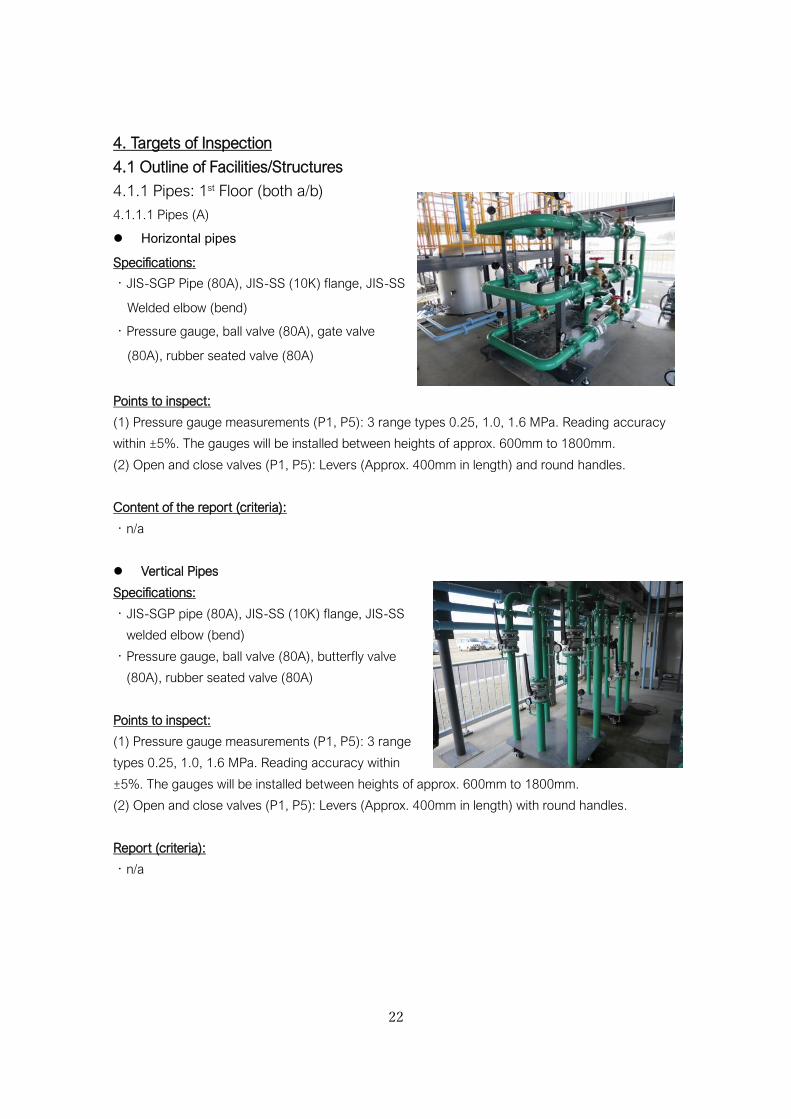
⚫ Vertical Pipes
Specifications:
・JIS-SGP pipe (80A), JIS-SS (10K) flange, JIS-SS
welded elbow (bend)
・Pressure gauge, ball valve (80A), butterfly valve
(80A), rubber seated valve (80A)
Points to inspect:
(1) Pressure gauge measurements (P1, P5): 3 range
types 0.25, 1.0, 1.6 MPa. Reading accuracy within
±5%. The gauges will be installed between heights of approx. 600mm to 1800mm.
(2) Open and close valves (P1, P5): Levers (Approx. 400mm in length) with round handles.
Report (criteria):
・n/a
23
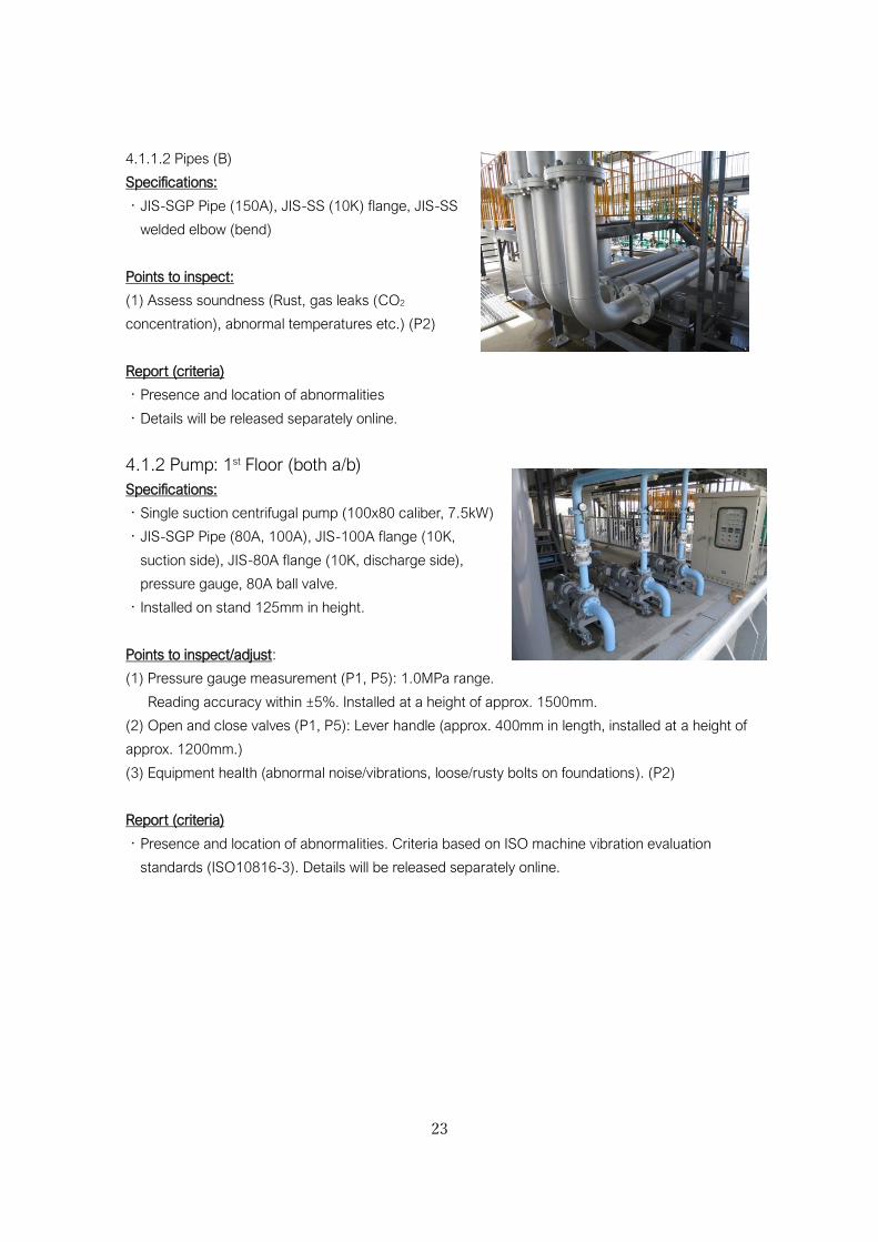
4.1.1.2 Pipes (B)
Specifications:
・JIS-SGP Pipe (150A), JIS-SS (10K) flange, JIS-SS
welded elbow (bend)
Points to inspect:
(1) Assess soundness (Rust, gas leaks (CO2
concentration), abnormal temperatures etc.) (P2)
Report (criteria)
・Presence and location of abnormalities
・Details will be released separately online.
4.1.2 Pump: 1st Floor (both a/b)
Specifications:
・Single suction centrifugal pump (100x80 caliber, 7.5kW)
・JIS-SGP Pipe (80A, 100A), JIS-100A flange (10K,
suction side), JIS-80A flange (10K, discharge side),
pressure gauge, 80A ball valve.
・Installed on stand 125mm in height.
Points to inspect/adjust:
(1) Pressure gauge measurement (P1, P5): 1.0MPa range.
Reading accuracy within ±5%. Installed at a height of approx. 1500mm.
(2) Open and close valves (P1, P5): Lever handle (approx. 400mm in length, installed at a height of
approx. 1200mm.)
(3) Equipment health (abnormal noise/vibrations, loose/rusty bolts on foundations). (P2)
Report (criteria)
・Presence and location of abnormalities. Criteria based on ISO machine vibration evaluation
standards (ISO10816-3). Details will be released separately online.
24
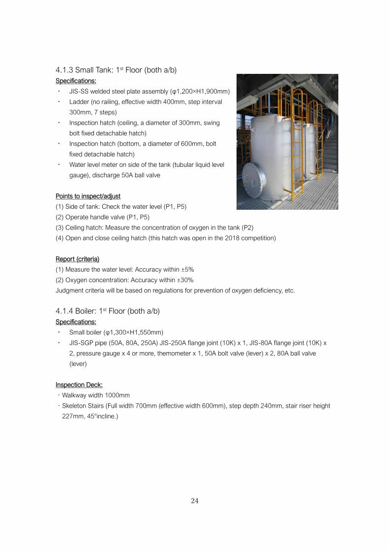
4.1.3 Small Tank: 1st Floor (both a/b)
Specifications:
・ JIS-SS welded steel plate assembly (φ1,200×H1,900mm)
・ Ladder (no railing, effective width 400mm, step interval
300mm, 7 steps)
・ Inspection hatch (ceiling, a diameter of 300mm, swing
bolt fixed detachable hatch)
・ Inspection hatch (bottom, a diameter of 600mm, bolt
fixed detachable hatch)
・ Water level meter on side of the tank (tubular liquid level
gauge), discharge 50A ball valve
Points to inspect/adjust
(1) Side of tank: Check the water level (P1, P5)
(2) Operate handle valve (P1, P5)
(3) Ceiling hatch: Measure the concentration of oxygen in the tank (P2)
(4) Open and close ceiling hatch (this hatch was open in the 2018 competition)
Report (criteria)
(1) Measure the water level: Accuracy within ±5%
(2) Oxygen concentration: Accuracy within ±30%
Judgment criteria will be based on regulations for prevention of oxygen deficiency, etc.
4.1.4 Boiler: 1st Floor (both a/b)
Specifications:
・ Small boiler (φ1,300×H1,550mm)
・ JIS-SGP pipe (50A, 80A, 250A) JIS-250A flange joint (10K) x 1, JIS-80A flange joint (10K) x
2, pressure gauge x 4 or more, themometer x 1, 50A bolt valve (lever) x 2, 80A ball valve
(lever)
Inspection Deck:
・Walkway width 1000mm
・Skeleton Stairs (Full width 700mm (effective width 600mm), step depth 240mm, stair riser height
227mm, 45°incline.)
25
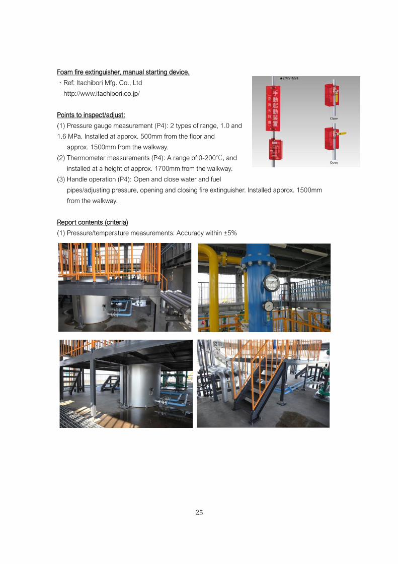
Foam fire extinguisher, manual starting device.
・Ref: Itachibori Mfg. Co., Ltd
http://www.itachibori.co.jp/
Points to inspect/adjust:
(1) Pressure gauge measurement (P4): 2 types of range, 1.0 and
1.6 MPa. Installed at approx. 500mm from the floor and
approx. 1500mm from the walkway.
(2) Thermometer measurements (P4): A range of 0-200℃, and
installed at a height of approx. 1700mm from the walkway.
(3) Handle operation (P4): Open and close water and fuel
pipes/adjusting pressure, opening and closing fire extinguisher. Installed approx. 1500mm
from the walkway.
Report contents (criteria)
(1) Pressure/temperature measurements: Accuracy within ±5%
26
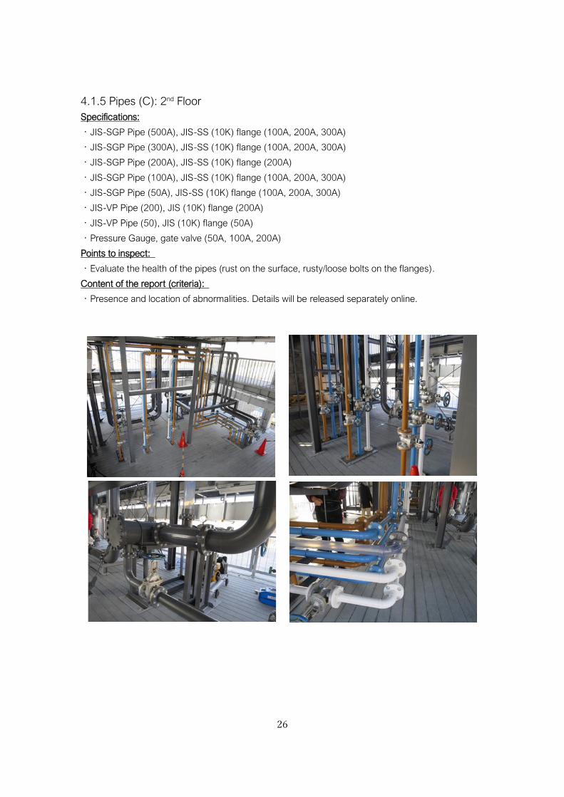
4.1.5 Pipes (C): 2nd Floor
Specifications:
・JIS-SGP Pipe (500A), JIS-SS (10K) flange (100A, 200A, 300A)
・JIS-SGP Pipe (300A), JIS-SS (10K) flange (100A, 200A, 300A)
・JIS-SGP Pipe (200A), JIS-SS (10K) flange (200A)
・JIS-SGP Pipe (100A), JIS-SS (10K) flange (100A, 200A, 300A)
・JIS-SGP Pipe (50A), JIS-SS (10K) flange (100A, 200A, 300A)
・JIS-VP Pipe (200), JIS (10K) flange (200A)
・JIS-VP Pipe (50), JIS (10K) flange (50A)
・Pressure Gauge, gate valve (50A, 100A, 200A)
Points to inspect:
・Evaluate the health of the pipes (rust on the surface, rusty/loose bolts on the flanges).
Content of the report (criteria):
・Presence and location of abnormalities. Details will be released separately online.
27
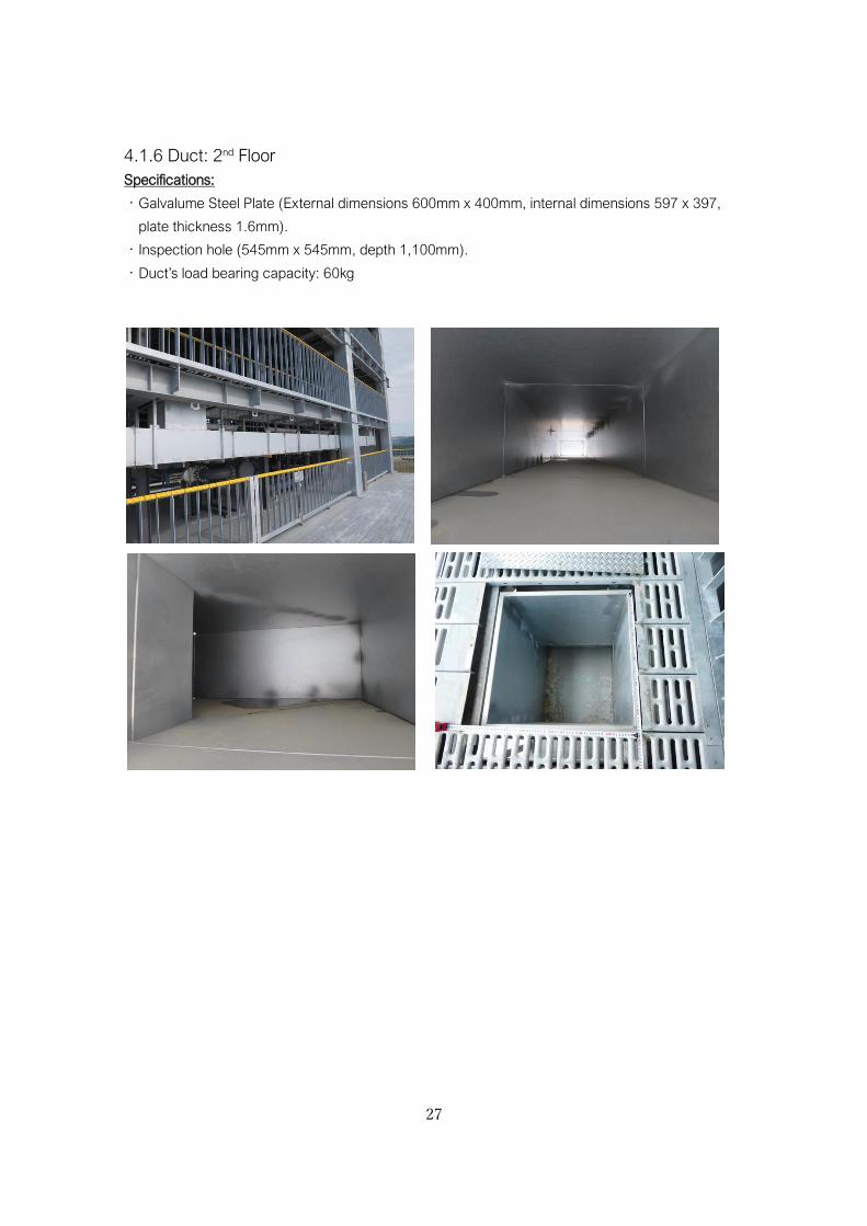
4.1.6 Duct: 2nd Floor
Specifications:
・Galvalume Steel Plate (External dimensions 600mm x 400mm, internal dimensions 597 x 397,
plate thickness 1.6mm).
・Inspection hole (545mm x 545mm, depth 1,100mm).
・Duct’s load bearing capacity: 60kg
28
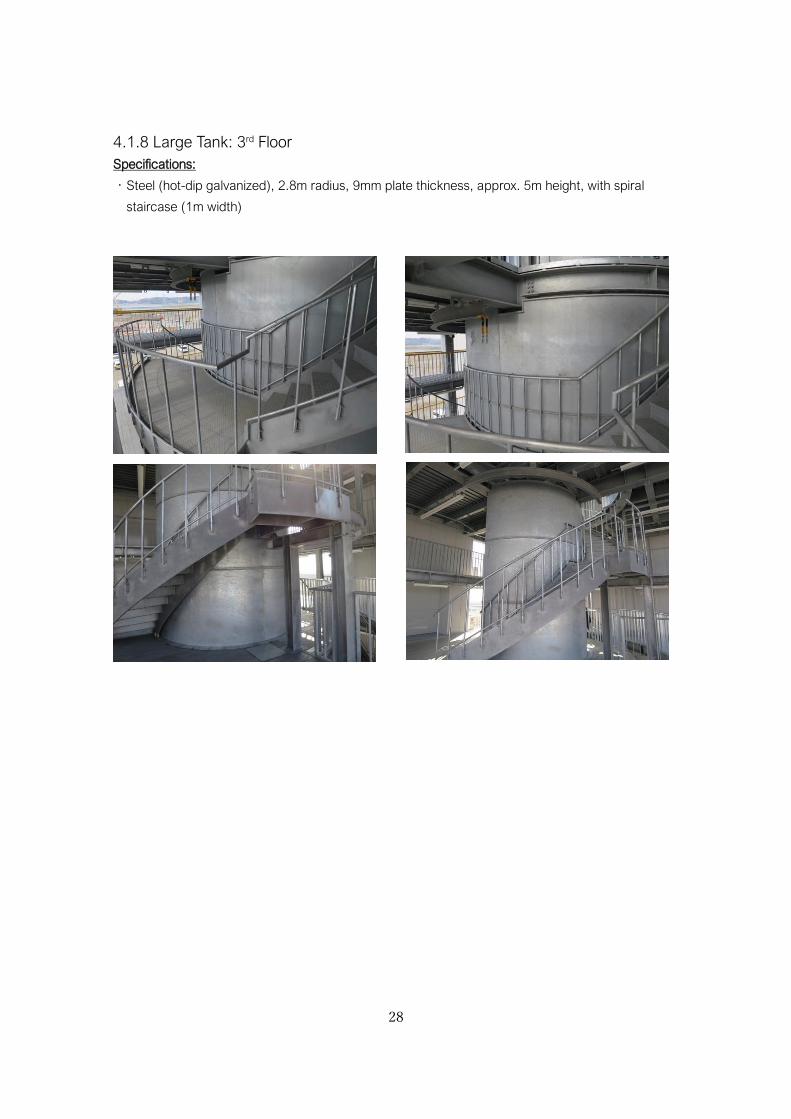
4.1.8 Large Tank: 3rd Floor
Specifications:
・Steel (hot-dip galvanized), 2.8m radius, 9mm plate thickness, approx. 5m height, with spiral
staircase (1m width)
29
4.2 Outline of targets to inspect/adjust
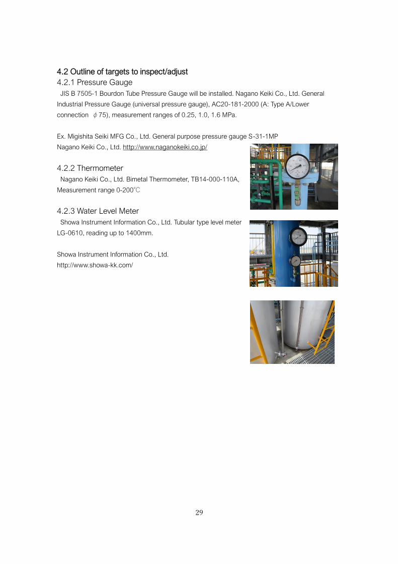
4.2.1 Pressure Gauge
JIS B 7505-1 Bourdon Tube Pressure Gauge will be installed. Nagano Keiki Co., Ltd. General
Industrial Pressure Gauge (universal pressure gauge), AC20-181-2000 (A: Type A/Lower
connection φ75), measurement ranges of 0.25, 1.0, 1.6 MPa.
Ex. Migishita Seiki MFG Co., Ltd. General purpose pressure gauge S-31-1MP
Nagano Keiki Co., Ltd. http://www.naganokeiki.co.jp/
4.2.2 Thermometer
Nagano Keiki Co., Ltd. Bimetal Thermometer, TB14-000-110A,
Measurement range 0-200℃
4.2.3 Water Level Meter
Showa Instrument Information Co., Ltd. Tubular type level meter
LG-0610, reading up to 1400mm.
Showa Instrument Information Co., Ltd.
http://www.showa-kk.com/
30
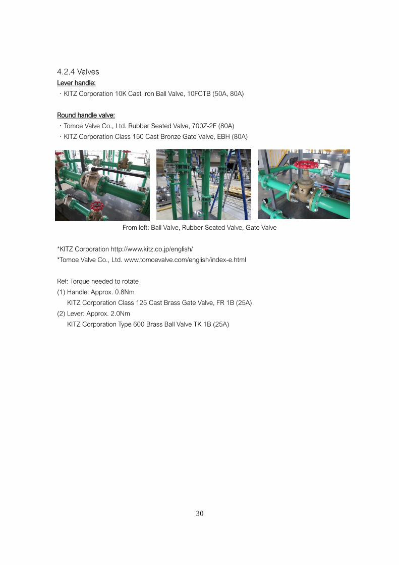
4.2.4 Valves
Lever handle:
・KITZ Corporation 10K Cast Iron Ball Valve, 10FCTB (50A, 80A)
Round handle valve:
・Tomoe Valve Co., Ltd. Rubber Seated Valve, 700Z-2F (80A)
・KITZ Corporation Class 150 Cast Bronze Gate Valve, EBH (80A)
From left: Ball Valve, Rubber Seated Valve, Gate Valve
*KITZ Corporation http://www.kitz.co.jp/english/
*Tomoe Valve Co., Ltd. www.tomoevalve.com/english/index-e.html
Ref: Torque needed to rotate
(1) Handle: Approx. 0.8Nm
KITZ Corporation Class 125 Cast Brass Gate Valve, FR 1B (25A)
(2) Lever: Approx. 2.0Nm
KITZ Corporation Type 600 Brass Ball Valve TK 1B (25A)
31
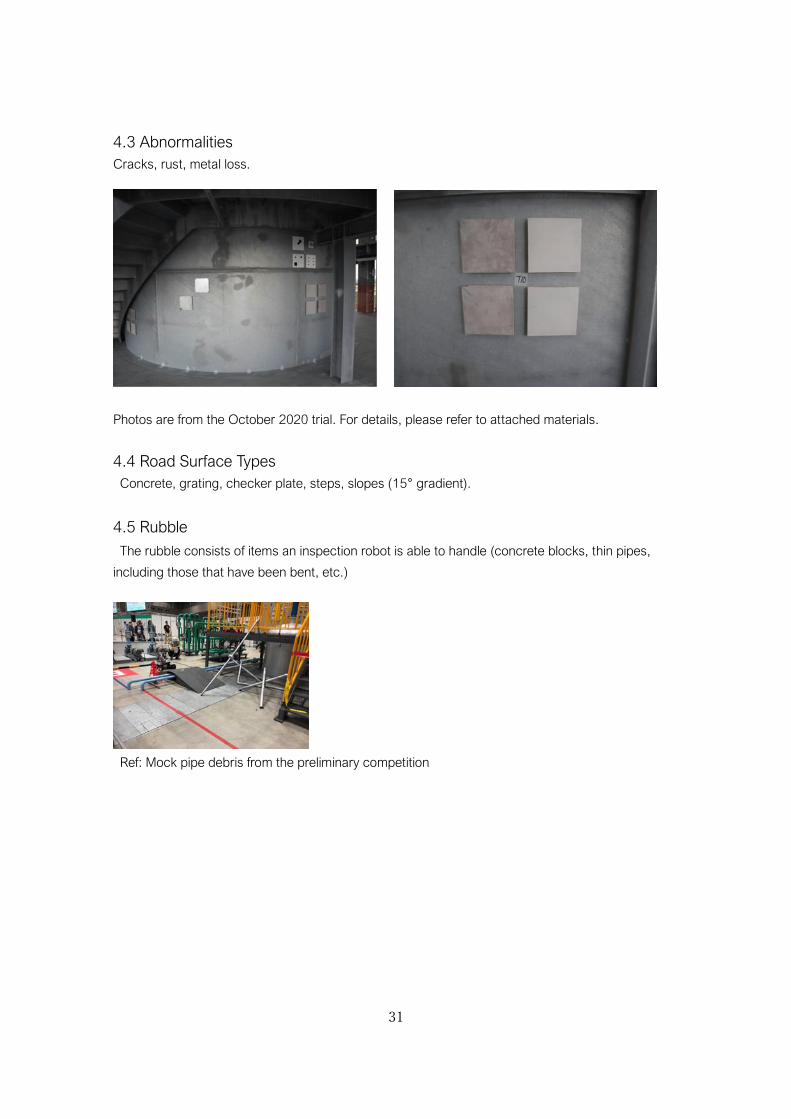
4.3 Abnormalities
Cracks, rust, metal loss.
Photos are from the October 2020 trial. For details, please refer to attached materials.
4.4 Road Surface Types
Concrete, grating, checker plate, steps, slopes (15° gradient).
4.5 Rubble
The rubble consists of items an inspection robot is able to handle (concrete blocks, thin pipes,
including those that have been bent, etc.)
Ref: Mock pipe debris from the preliminary competition
32
5. Competition Schedule
Schedule: Set up (robot inspections) - 1 day, Qualifying rounds - 3 days, Final - 1 day.
There will be no postponement for rain (waterproofing measures for robot and control console are
essential).
・The competition field’s building does not have outer walls, so rainwater may blow in.
・Rainwater may flow down from the upper levels.
・Test run period is planned for the morning of the first day of qualifying rounds.
Competition time:
・ Qualifying round: 30 mins/mission (set up 5 mins, compete 20 mins, removal from field 5 mins.)
・ Final: 40 mins/mission (set up 5 mins, compete 30 mins, removal from field 5 mins.)
・ Team changeover time: 5 mins.
6. Scoring
Competition points are the total “mission points”, “technical points”, and “time points” for each
mission.
6.1 Mission Points: Assessing the Mission’s Level of Achievement
The points gained for completing the competition tasks within each mission are called “mission
points”. The level of achievement for each mission is assessed through the mission points. However,
during a certain part of Mission P5, when the robot used for the mission passes through a check point
area it will gain arrival points. Arrival points = number of arrival check points passed x 10 points.
6.2 Technical Points: Assessing the Robot’s Technical Level
Teams that implement advanced robotic technology will be awarded technical points. Technical
points will be added depending on the type of technology and number of technology types. They will
be calculated as 10% to max 20% of the points for each mission. Technical points will be authorised
based on a hearing by the judges during the robot inspections before the competition. Teams may be
required to demonstrate their robot’s technical capabilities.
Here are some examples:
(i) Is able to move autonomously to specified areas for inspection/operation, as well as patrol the
surrounding area.
(ii) Can automatically recognise a handle’s position, and autonomously operate it.
(iii) Can report the results of an inspection for abnormalities as a numerical reading. (e.g., issues
with a pump, loose bolts.)
(iv) Wipe off the penetrant on the crack test piece.
(v) Is able to create a map in real time, with the results of its inspection and evaluation displayed on
the generated map.
(vi) Energy-saving measures have been taken into account (self-report).
(vii) Can deal with adverse environments (water/dust proof (IP), explosion proof), (self-report).
33
*For (vii), ability will be determined by providing evidence (a certificate etc.).
*Automatic meter reading is required for reading instruments in the 2021 competition.
※During the competition, alert the judges when employing automation/automatic control.
6.3 Time Points: Assessing the time taken to complete missions
We plan to award points for completing each mission within a certain time.
6.4 Terms for Tallying Points and Determining a Winner
Regarding the competition points, the overall score is the total of “mission points”, “technical points”
and “time points”, and the points awarded to each team are standardised by the maximum number
of points available for each mission. The teams that can progress to the final will be the 3 teams with
the most points awarded in the qualifying rounds.
7. Team Members
A maximum of 6 team members can apply via the Team Description Papers (TDP). Only team
members may enter the paddock and competition areas.
The roles of the team members are determined as follows:
・Team leader (1 person): Organises the team. Only the team leader may dispute the competition
results.
・Robot Operator (2 people): The person who controls the robot. The robot operators may enter
the operator area.
・Network Administrator: Manages the team’s network.
・Safety Manager (1 person/robot): Monitors the robots during mission attempts, and ensures
the safety of the surrounding area.
・Assistants: Help to transport the robot between the start area and the paddock, and between the
restart point and the start area. They also remove the robot from the field once the mission is over.
Only the team leader and the robot operators may enter the operation area when competing. Robot
operators and safety managers must not share the same role. Other roles may be held concurrently,
and apart from the team leader members may switch roles for each mission.
Additional members and other changes must be applied for in advance.
8. Competition robots
・There are no restrictions on the shape of the robot. They may take any shape, be it crawler, drone,
humanoid, legged, serpentine, etc.
・Robots may only be operated or remotely controlled from the designated operation area.
・There is no limit on the number of robots that may be used in the competition. However, there are
the following constraints.
- At the start of the mission, the total projected area on the ground (ground contact area) of all
robots in the starting position, must not exceed the start area of 1.44m² (1.2m x 1.2m). However,
robots brought in halfway through, will be measured in the state they were moved in.
34
- There are no height restrictions.
- Once the mission has started, the robot’s ground contact area may exceed 1.44 m².
・The maximum weight of the robot is 130kg/robot.
・The competition robots and control consoles are limited to those described in the team description
papers. However, only changes and additions to the competition robot(s) that are notified at least
2 weeks before onsite participant registration, and are accepted by the organisers, will be allowed.
・Only robots and control consoles that pass the inspection carried out in advance of the competition
are allowed to compete. However, separate safety tests for drones will be carried out onsite. Details
of robot inspections and safety tests will be released at a later date.
・It is possible to make changes to the competition robot between missions, but no changes may be
made during the mission.
・Only batteries that have safety guarantees may be used.
・An emergency stop switch/button must be installed.
・Teams are responsible for preparing for an emergency (such as a fire) should their robot
malfunction.
・Teams must comply with the law, such as the Radio Act, of the competition country (Japan).
・As a safety measure for traversing stairs, robots must be fitted with eye plates or eye bolts so that
a chain block or a safety belt (lanyard, auto belay, etc.) can be attached with a carabiner. Robots
that cannot be attached with a safety belt will not be able to participate in the mission.
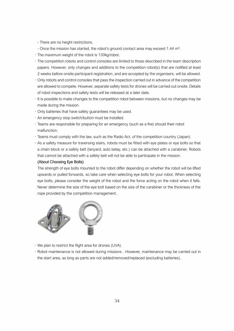
(About Choosing Eye Bolts)
The strength of eye bolts mounted to the robot differ depending on whether the robot will be lifted
upwards or pulled forwards, so take care when selecting eye bolts for your robot. When selecting
eye bolts, please consider the weight of the robot and the force acting on the robot when it falls.
Never determine the size of the eye bolt based on the size of the carabiner or the thickness of the
rope provided by the competition management.
・We plan to restrict the flight area for drones (UVA).
・Robot maintenance is not allowed during missions . However, maintenance may be carried out in
the start area, as long as parts are not added/removed/replaced (excluding batteries).
35
9. The Missions
Mission achieved:
All missions specified in the inspection instructions are completed, and the robot has returned to the
start area, within the time limit.
Declaration of mission end (withdrawal):
The team leader can declare the end of the mission if the robot is unable to operate, or is unable to
gain further points.
Restart:
Once the mission has started, the team leader can request a restart to deal with a technical
malfunction. The emergency stop switch may also be pressed at the discretion of the assistant referee.
When the referee allows a restart, a 2-minute penalty will be incurred from the time the restart is
approved (all robots have been stopped).
Once a request has been made, the team safety manager and/or assistant must move the robot
back to the start area. The points gained for the task so far will be retained. However, after restarting
the mission, tasks already completed may not be attempted again.
Communication between operation area and assistants:
If the robot operator needs to communicate with team members outside of the operation area, they
must use the voice communication system onboard the robot, or the transceiver provided by the
organisers. You must not give any information that is beneficial to the competition. This
communication must be in a language the judge can understand (English or Japanese).
Dangerous behavior: Teams who perform the following actions will be subject to a large point
reduction or disqualification from the competition.
- Obstruct another team
- Damage to the competition field that takes longer than 10 minutes to repair.
- Ignoring measures to prevent the spread of CORVID-19.
- Other actions deemed dangerous by the referees.
Other points to note:
- Teams may not enter the competition field outside of their test run and competition time.
- The team safety manager must accompany the robot during the mission in case of unforeseen
circumstances.
- The team leader may challenge the mission results by declaring their objection to the referees.
Objections must be made in the time the robot is being removed from the field.
- The screen of the operator’s PC needs to be able to be output through HDMI. To aid social distancing
and prevent the spread of CORVID-19, it is preferable to have multiple display screens set up.
36
10. Communication Network
Teams should set up their own network between the operator’s computer and the robot. Use of a
wireless or wired connection is allowed. Each floor will have a LAN outlet creating a network between
the operator area and each floor. This communication network must comply with the communication
regulations detailed separately.
11. Awards
The ranking will be decided based on the scores (see chapter 6).
12. Miscellaneous
All teams must follow the instructions of the competition organizers.
Revision History
Ver.0.20 (2019/4/13): First draft
Ver.0.36 (2019/6/19): Tentative
Ver.0.40 (2019/8/10): Revised
Ver.1.52 (2020/12/14): Public
Ver.1.53 (2021/9/21): Public