Embed Size (px)
Citation preview

White Paper |
EnterpriseAirWave VisualRF Location and Mapping:
Improving Operations Efficiency Throughout
the Wireless Network Lifecycle
1 AirWave VisualRF: Improving Operations Efficiency Aruba Networks
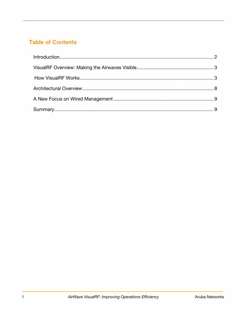
Table of Contents
Introduction .................................................................................................................. 2
VisualRF Overview: Making the Airwaves Visible ......................................................... 3
How VisualRF Works ................................................................................................... 3
Architectural Overview ................................................................................................. 8
A New Focus on Wired Management .......................................................................... 9
Summary...................................................................................................................... 9
2 AirWave VisualRF: Improving Operations Efficiency Aruba Networks
1. Introduc tion Driven by the need for mobility, higher productivity and cos t reductions through network rights izing, wireles s networks are becoming ubiquitous within all enterpris es , government organizations and educational ins titutions . As wireles s evolves into the primary means of connectivity for s ome of the organization’s mos t important us ers , network managers need to be more effic ient in how they plan, manage and protect their growing wireles s LANs (WLANs ). IT organizations are quickly dis covering that WLANs bring a unique s et of characteris tics , including:
• Us ers that connect from different locations at different times , and s ometimes with different devices
• Dependence on a medium that is out of IT’s control ----- the air To really unders tand what is happening on your wireles s network, IT needs the ability to monitor the whole R F environment ----- down to the device and us er level. Unfortunately, very few s olutions provide this level of vis ibility. The bes t s olutions take into account the full complexity of the R F environment and addres s the following requirements :
• P redic tive and dynamic s ampling. P urely predictive or s ite s urvey tools only offer a s imple s naps hot or s tatis tical s ampling of the environment. S olutions need to combine both predictive models and s ampling of real-world data to effectively s upport the full network lifecycle from planning to troubles hooting.
• Multi- vendor s upport. P roducts that only manage a s ingle vendor’s infras tructure ----- or even a s ingle generation of that vendor’s products ----- provide a s imilarly incomplete picture. S upport for multi-vendor and multi-architecture environments is critical to provide a complete picture of the R F environments that exis t in mos t enterpris es .
• F ull- time loc ation engine. P roducts that only capture location data during troubles hooting events typically are not as fas t or accurate as an engine that continuous ly tracks the location of every device.
• Leveraging exis ting infras truc ture. Tools that focus only on location s ervices typically require expens ive dedicated infras tructure components , s uch as s ens ors and exciters , plus s eparate application s ervers . Thes e added cos ts put the s olutions out of reach for many organizations .
• Trac king ac ros s the edge of the network. Mos t AP s us e power over E thernet to acquire power and data through one cable. However, beyond 300 feet of wired cable, wired s ignals pas s ed to the AP can be s ignificantly degraded. E ffective s olutions can vis ually model capacity and power cons traints , which is a valuable capability in capacity planning.
AirWave Vis ualR F™ Location and Mapping provides an end-to-end wireles s network vis ualization and lifecycle management s olution from initial s ite planning to ongoing R F monitoring. As a feature of the AirWave Wireles s Management S uite™ from Aruba Networks , Vis ualR F us es dynamic s ignal propagation technology to accurately calculate s ignal coverage and the precis e location of every wireles s device in range of the WLAN. Vis ualR F expos es this information via an interactive web interface, dis playing fully integrated maps and location information. With Vis ualR F, organizations can s olve network problems fas ter, reduce cos ts , improve s ervice quality for us ers and make better- informed network planning and deployment decis ions .

3 AirWave VisualRF: Improving Operations Efficiency Aruba Networks
2. Vis ualR F Overview: Making the Airwaves Vis ible Vis ualR F automatically generates a real-time picture of the R F environment s o that IT s taff can vis ualize the entire network from the core infras tructure and throughout the entire R F environment without having to leave their des ks . Vis ualR F offers s ignificant advantages :
• S aves time. Vis ualR F creates a live map of the entire wireles s network infras tructure and automatically tracks any device that as s ociates with the network, inc luding laptops , printers , s martphones and even many Wi-F i as s et tags ----- without any additional s etup. Up-to-date R F heat and channel maps as well as highly accurate location data help the s ervice des k and Level 2/3 s upport s taff to pinpoint and res olve coverage problems fas ter with les s direct involvement from us ers .
• S aves money. As an integrated feature of AirWave, Vis ualR F is very cos t-effective to deploy. It leverages exis ting real-time information from the network infras tructure. There is no need to ins tall s eparate dedicated s ens ors , exciters or location appliances , nor does the product require expens ive s ite s urveys or the input of walls and wall properties . The product’s bulk floor plan import capability s aves hundreds or thous ands of man-hours during s etup for organizations with large networks compris ing thous ands of locations . C ons equently, organizations c an gain higher value without adding anything to their exis ting infras tructure.
• R obus t vis ibility. Vis ualR F couples predictive modeling with calc ulated modeling bas ed on real R F s amples to produce the mos t accurate representation of the R F environment. As a res ult, Vis ualR F provides a complete picture of your network, even in multi-vendor, mixed-architecture environments that combine thick and thin acces s points (AP s ), mes h AP s , point-to-point AP s , 802.11 and WiMAX.
• Improves s ervic e quality. G ood network planning is crucial, s ince infras tructure deployment mis takes may be cos tly and time-cons uming to fix. Vis ualR F helps you do it right the firs t time, heading off potential s ervice calls from frus trated us ers . If you do have a coverage gap, Vis ualR F makes it c lear where the problem exis ts s o you can take immediate, appropriate action.
• E nables s marter planning. Vis ualR F enables companies to intelligently plan campus es , buildings , floors and AP s . C omplete bills -of-materials allow planners and ins tallation contractors to s treamline the quote and ins tallation proces s for both the wired and wireles s infras tructure.
• Improves s ec urity. Vis ualR F helps you quickly locate rogue devices within your WLAN, as well as devices that are out of security compliance.
3. How Vis ualR F Works Vis ualR F provides a comprehens ive view of the entire building and campus network infras tructure, enabling IT to s ee exactly who is on the network, where they are located and how the overall network is performing. Vis ualR F requires few resources to s et up, deploys cos t-effectively and provides s ignificant advantages throughout the entire wireles s network lifecycle from pre-deployment provis ioning and planning to ongoing monitoring and troubles hooting to rogue AP detection and threat mitigation.
3.1 S etup and T uning Ins talled on the s ame s erver as the AirWave Management P latform™ (AMP ) s oftware, Vis ualR F s etup is fas t and s traightforward. Once activated, the feature leverages R F data from your exis ting infras tructure, including all your routers and acces s points that are managed by AMP . All location engines require uploading floor plans and locating acces s points . Vis ualR F has refined the process to make it as eas y as

4 AirWave VisualRF: Improving Operations Efficiency Aruba Networks
pos s ible. Y ou can upload files directly into the s erver or utilize Vis ualR F P lan, a des ktop vers ion of Vis ualR F’s planning capabilities that does not require access to the s erver. Vis ualR F s upports all vers ions of C AD, including DWG , DWF and DFX formats . It als o s upports J P E G , G IF, B MP and P NG file formats . Vis ualR F automatically inherits s ize information s tored in C AD files while providing cropping, de-layering and de-coloring capabilities . For organizations with multiple campus es , buildings , and floor plans , a batch upload feature is available to import thous ands of files programmatically, s aving hundreds of s taff hours . In one cas e, a retailer es timated that it would take a full s taff-year to upload its 2,000 floor plans . It was pleas antly s urpris ed when one employee us ed Vis ualR F’s batch upload capabilities to complete the tas k in jus t one week! Vis ualR F automatically incorporates live R F data from all managed acces s points and inherits device-type grouping information from AMP . For companies with multi-vendor and mixed-architecture environments , Vis ualR F automatically normalizes R F data from multiple vendors ’ AP s and acros s different product lines from the s ame vendor. Different types of as s ociated client devices are dis played us ing different icons , allowing us ers to eas ily view and monitor the s tatus of a wide range of devices , including laptops , P DAs , Wi-Fi as s et tags and wireles s VoIP phones . Y ou can plan s witches and routers and depict them within an wiring c los et (or IDF). Unders tanding the wired topology enables Vis ualR F to help with the root caus e of wireles s is s ues that are actually related to the wired network. Vis ualR F generally achieves res olution below 10 meters in properly deployed WLAN ins tallations without requiring s pecial s ens ors or s ite s urveys . It offers a number of features that help refine location accuracy, including:
• A location accuracy tes ting tool, which records location accuracy and allows you to compare before-and-after res ults before making changes to the R F environment.
• A remote s ite s urvey tool that allows you to perform cos t-effective s urveys us ing any client connected to the infras tructure without the burden of carrying a s pecialized device to the phys ical location. For example, you can ins truct Vis ualR F to take s ignal s amples from a s pecific c lient device at a known location coordinate to es timate the path los s at that particular area of a floor. This increas es the location and path los s accuracy for all c lients in that s pecified area.
3.2 P re- Deployment P lanning and P rovis ioning
Intelligent planning can s ave s ubs tantial time and cos ts by avoiding the need to reins tall or reconfigure a wireles s network that does not meet coverage requirements . Us ing Vis ualR F, wireles s network engineers can quickly model floor plans for wireles s and wired infras tructures , s pecifying precis e controller and access point locations , as well as determining the required wired ups tream infras tructure. As a res ult, Vis ualR F helps organizations optimize network performance before any infras tructure is put in place. Vis ualR F includes Vis ualR F , a web-bas ed network planning application that can run on the AMP s erver, and Vis ualR F P lan, which operates locally on your des ktop. B oth Vis ualR F and Vis ualR F P lan leverage the s ame code bas e and deliver the s ame planning feature s et within a cons is tent us er interface. Y ou can automate the import and export of s ite plans between Vis ualR F and Vis ualR F P lan. AirWave provides Vis ualR F P lan free of charge for any cus tomers with a valid Aruba s upport agreement. Networks planned within Vis ualR F P lan can be exported to Micros oft® Word format, making it eas y to s hare information with your extended team. The Vis ualR F planning proces s cons is ts of the following s teps :
1. Upload your floor plans . Whether you are ins talling a wireles s network for the firs t time or expanding an exis ting one, Vis ualR F P lan can facilitate the planning proces s . B efore you have your AMP s erver in place, you can import your campus es , buildings and floor plans to the Vis ualR F s ys tem from Vis ualR F P lan, C is co WC S , and Aruba OS or R F P lan. Y ou can manually upload floor plans bas ed on a wide range of formats , including C AD, J P E G and G IF.

5 AirWave VisualRF: Improving Operations Efficiency Aruba Networks
2. P lac ing wireles s networking equipment on a floor plan. Vis ualR F optimizes AP placement by
analyzing your floor plan and determining the number and exact location of AP s bas ed on the following variables : coverage criteria, building characteris tics , manufacturer and model. For example, you could es tablis h that all areas in your building mus t have a certain level of coverage. The product inc ludes a wireles s catalog that contains all of the R F characteris tics for any device s upported in AirWave, including minimum receive s ens itivities per radio, antenna gain and antenna coverage properties , s o that your des ign takes into account the unique characteris tics of your chos en infras tructure. If you are planning to us e Aruba air monitors as an overlay sys tem for your wireles s intrus ion protection s ys tem (WIP S ), Vis ualR F can optimize placement of thes e s ens ors .
3. P lac ing wired network equipment on a floor plan. To as s is t in the planning proces s , Vis ualR F
provides the capability to plan for wired network equipment neces s ary to s upport the WLAN
equipment. It provides a view that dis plays the dis tance between the AP and the IDF. This allows you to determine the neces s ary required cabling and power requirements of the planned AP , as well as verifies that the planned wired devices will meet your requirements .
4. Validation and purc has ing. Vis ualR F automatically generates bill-of-material reports . The B OMs provide a hard-copy validation of the technical requirements (in terms of des ired R F characteris tics ) and a complete lis t of equipment (wired and wireles s ) required to ins tall the network. This information makes purchas ing and contracting for phys ical ins tallation much eas ier becaus e you have a table of part numbers and quantities with a graphical repres entation of the network. The report can be delivered in HTML or Micros oft Word 2007 format.
3.3 Network Monitoring and Troubles hooting
Vis ualR F enables organizations to reduce the s upport and operational cos ts as s ociated with managing a wireles s network. In addition to providing a real-time view of the R F environment, the product automatically tracks the location of all devices that as s ociate with the network, including laptops , printers , s martphone and Wi-Fi as s et tags . A number of capabilities are available to IT s taff ----- both s ervice des k and Level 2/3 s upport s taff ----- to as s is t in troubles hooting. F irs t and foremos t, Vis ualR F provides real-time vis ual overlays , including:
Figure 1: Vis ualR F auto-provis ions AP s on a floor plan.

6 AirWave VisualRF: Improving Operations Efficiency Aruba Networks
• Heat maps ----- depict the s trength of the R F coverage in each location. Vis ualR F us es a unique dynamic R F s ampling technique that incorporates AP -to-AP , AP -to-client and AP -to-rogue data to build an attenuation grid that graphically indicates coverage levels . If you have dedicated s ens ors in place, the data from thos e s ens ors (s ens or-to-AP , s ens or-to-client and s ens or-to-rogue) will als o feed into the dynamic R F s ampling. Vis ualR F automatically recalculates the path los s and device locations as it receives real-time data from the wireles s LAN.
• Data rate ----- calculates the data rate at every location us ing dynamic R F s ampling.
• C olor- c oded c hannels ----- help reduce interference and recommend R F channel and other s ettings for optimal performance and coverage.
• Voic e overlay ----- indicates how well the network is functioning relative to voice coverage.
• G oogle E arth integration ----- s hows device locations and mes h network links for outdoor deployments .
• S ens or c overage ----- this features dis plays the areas that are covered by your air monitors and thos e that are not, s o that you can verify that you are providing adequate coverage for rogue s canning.
Figure 2: Vis ualR F’s heat map view depicts the s trength of the R F coverage in each location.

7 AirWave VisualRF: Improving Operations Efficiency Aruba Networks
Vis ualR F includes location playback capabilities , allowing you to play back up to 24 hours of location his tory on your s creen. This capability as s is ts with troubles hooting ----- for example, if a us er is not s ure exactly where he or s he was when a problem occurred ----- and with finding los t or s tolen devices . Vis ualR F als o dis plays the ‘‘las t known location’’ if a device dis appears off the network. With Vis ualR F, us ers cus tomize their view to s uit s pecific preferences and requirements . For example, the feature offers :
• Vis ual alerts and pers onal thres holds ----- us er-defined alerts and error conditions can be dis played on the floor plan, c learly indicating the alert location and making error patterns eas ier to res olve. Alerts can be bas ed on pre-defined thres holds or Y E S /NO and are color-coded for higher vis ibility. For example, you can es tablis h s pecific breakpoints for when a us er cons uming large amounts of bandwidth s hows up as green, yellow or red.
• G rid lines ----- Vis ualR F layers grid lines on the coverage map, facilitating a more intuitive view for troubles hooting in s ome phys ical environments .
• C us tom devic e types ----- us ers can cus tomize device type icons inc luding the icon s ize, for example to dis tinguis h a laptop from a printer. If you have a previous ly deployed network that is experiencing coverage problems , you can us e Vis ualR F to determine if coverage will improve if you add more AP s . Y ou can review before-and-after R F maps to compare the current s etup to the propos ed optimal configuration. In addition, you can addres s potential coverage problems proactively with a ‘‘s imulate failure’’ feature that allows you to examine what happens if an exis ting AP fails . This allows you to incorporate the right level of redundancy into mis s ion-critical networks .
3.4 Managing S ec urity and C omplianc e
Vis ualR F integrates with AirWave R AP IDS ™ , the rogue detection feature of AirWave Wireles s Management S uite, and provides rogue AP locations on your floor plans for fas ter mitigation and removal. The feature provides c lues as to which wired s ubnet any rogue devices are located in. Vis ualR F can als o validate coverage for dedicated s ens ors s uch as Aruba air monitors for better location accuracy and P C I compliance.
Figure 3: Vis ualR F dis plays the locations of all rogue devices found by R AP IDS .
As s et Trac king: R eal World S c enario A univers ity library that offered rental computers had los t one of its computer units . Weeks after it was reported mis s ing, the IT department located the unit us ing Vis ualR F. The IT team us ed AirWave Wireles s Management S uite to s et an alert to be triggered when the device was as s ociated to the wireles s network. When the machine was eventually turned on, the alert was received, and the IT team was able to us e Vis ualR F to track it down to a cart in a s torage closet.

8 AirWave VisualRF: Improving Operations Efficiency Aruba Networks
4. Arc hitec tural Overview Vis ualR F is an integrated feature of AirWave. At the core is the AirWave Management P latform (AMP ), which provides effic ient centralized management of the wireles s infras tructure. AMP communicates with AP s , controllers , s witches and routers over S NMP at configurable intervals . Thes e components return a vas t amount of R F s ignal information, s uch as AP -to-AP , AP -to-client, and AP -to-rogue, which when received by AMP , is routed to Vis ualR F. As a full-time location engine, Vis ualR F continually calculates R F coverage and device locations for all wireles s c lients within your WLAN airs pace. In addition, through integration with the R AP IDS feature, Vis ualR F calculates the location of rogue devices and all devices that are as s ociated with the wireles s network. Vis ualR F then pres ents this data to the us er via a Flas h interface.
Vis ualR F is unparalleled in the way it calculates path los s and device locations . AirWave us es a combination of both dynamic R F s ampling to determine s ignal path los s at a particular s ite and a predictive model bas ed on the s ite plan and infras tructure s pecifications for areas where R F s ampling is n’t available. Vis ualR F has a number of configuration s ettings that allow you to cus tomize and optimize it for your phys ical and operational environments , inc luding how frequently it calc ulates device locations or device tracking s ens itively thres holds . This allows you to s et different device tracking movement thres holds depending on the s pecific environment to give you the mos t accurate, relevant location information. For ins tance, you could cus tomize the s ettings for an office building that won’t have as much device roaming as a warehous e, where the client devices are mounted on forklifts and cons tantly move. Vis ualR F takes a dis tinctive approach to s olving location challenges within a wireles s environment. It leverages R F data from the exis ting infras tructure to build a near real-time attenuation grid. Vis ualR F continuous ly tunes and adjus ts this grid bas ed on inc oming data s amples while including a s mall portion of predictive modeling for thos e areas that might not provide continuous R F s amples . This approach
Figure 4: The AirWave Management P latform, a core component of the AirWave Management S uite, provides efficient, centralized management of your wireles s infras tructure and vis ibility acros s the wired edge of your network.
9 AirWave VisualRF: Improving Operations Efficiency Aruba Networks
enables Vis ualR F to work immediately out-of-the-box without requiring time-cons uming s urveys , drawing walls on the floor plan or ins talling s pecial hardware. All of the location information is integrated into AMP as well and available via XML AP I. The AP I provides an open, s imple integration with a variety of third-party applications , s uch as public s afety and fixed as s et tracking. AirWave cus tomers us e Vis ualR F’s to reduce s upport calls , s ave money, improve productivity and make campus es s afer.
5. A New F oc us on Wired Management Wireles s networks don’t operate in a vacuum. Their operation and reliability depend on a number of wired infras tructure components . With AirWave, Vis ualR F’s real-time views incorporate wired and wireles s components . This expans ion enables end-to-end vis ibility ----- from the client device to the AP , edge s witch, controller and core s witch. A new wired overlay s hows AP -to-wiring clos et relations hip information, including phys ical cable length and power los s . From this dis play, you can drill down into a detailed IDF view that s hows the racks and s erver locations , as well as the s witc h locations in thos e racks , along with AP -to-port mapping. Thes e features are extremely benefic ial for network expans ion planning or in green-field deployments . Vis ualR F facilitates more effective communication between remote pers onnel and on-s ite pers onnel and reduces finger-pointing. For example, if cabling needs to be moved or s wapped, a network engineer can eas ily view and relay s pecific rack, s witch or port information to on-s ite colleagues . It als o enables a more comprehens ive planning proces s that takes a full account of all network requirements and generates a s ingle bill-of-materials report for necess ary wired and wireles s equipment. Finally, it aids in planning power and backplane capacity in the remote IDF.
6. S ummary Organizations acros s almos t every indus try are ins talling or expanding their wireles s networks to improve productivity and control cos ts . Meanwhile, C IOs continue to s truggle with network operations and s ecurity is s ues as well as how to extract higher returns from their wireles s network inves tments . AirWave Vis ualR F provides an end-to-end vis ualization s olution from initial s ite planning to real-time R F monitoring. It helps a wide range of organizations s olve problems fas ter, improve s ervice quality, make well- informed bus ines s decis ions and boos t their wireles s network R OI.
Loc ation S ervic es : R eal World S c enario Like many univers ities , Univers ity of C incinnati was experiencing an explos ion in the number of s tudents with mobile phones . At the s ame time, it needed to provide location-bas ed s ervices to s tudents who us ed their cell phones for general as s is tance, s uch as directions to s pecific des tinations , campus s afety (non-emergency) calls s uch as reques ts for late-night es corts , as s is tance with parking and other infractions , and emergency call as s is tance. The Univers ity wanted to enable s tudents to dial *UC and have the call routed to the main P B X. The caller’s number is then identified and us ed for a databas e lookup, res ulting in the caller’s databas e record being automatically pus hed to the call center operator’s s creen. At the s ame time as the databas e record lookup, the application s hows the caller’s location on a campus map. If the caller requires as s is tance from campus public s afety, the initial ans wering agent forwards the call to the public s afety dis patcher, who has access to the s ame caller’s record, campus map and location information without any further intervention.

10 AirWave VisualRF: Improving Operations Efficiency Aruba Networks
AirWave Vis ualR F F eatures
B enefits
S imple s etup proces s with no additional s ens ors , s ervers or s ite s urveys
C aptures valuable data with little up-front cos t.
S ingle web-bas ed interface for s erver and offline planning
S aves time in the trans ition from planning to deployment. P rovides planning capabilities to contractors and outs ide partners without giving them full monitoring access to your management s erver.
Automated planning s upport and bill of materials
S implifies the quote and build-out cycle. Makes it eas ier to jus tify infras tructure purchas es .
G raphical overlays , s uch as heat maps , data rate, channel and voice
S aves time and improves s ervice level by enabling fas ter root caus e analys is and troubles hooting.
Accurate location data
Allows quick location of us ers and wireles s devices for troubles hooting, planning, and as s et tracking. Als o improves s ecurity.
Location playback and ‘‘ las t known location’’
Improves troubles hooting capabilities . As s is ts in locating los t or s tolen devices .
Vis ual alerts and pers onal thres holds
Accelerates troubles hooting and improves s ervice levels by proactively notifying s taff of important conditions and helping them quickly pinpoint problems .
P redictive modeling for what-if planning and ‘‘s imulate failure’’
Addres s es potential coverage problems proactively and helps plan for the right level of redundancy in mis s ion-critical networks .
Open, XML-bas ed AP I
Makes it eas y to incorporate valuable location data into external applications .
Integrated architecture
S aves money by eliminating the need for s eparate location s ens ors , exciters or s ervers .
Multi-vendor, mixed-architecture s upport
Fas ter implementation, accurate heat maps and location information in multi-vendor, mixed-architecture environments .
11 AirWave VisualRF: Improving Operations Efficiency Aruba Networks
About Aruba Networks Aruba is the global leader in dis tributed enterpris e networks . Its award-winning portfolio of campus , branch/teleworker, and mobile s olutions s implify operations and s ecure acces s to all corporate applications and s ervices - regardles s of the us er's device, location, or network. This dramatically improves productivity and lowers capital and operational cos ts .
Lis ted on the NAS DAQ and R us s ell 2000® Index, Aruba is bas ed in S unnyvale, C alifornia, and has operations throughout the Americas , E urope, Middle E as t, and As ia P acific regions . To learn more, vis it Aruba at arubanetworks .com. For real-time news updates follow Aruba on twitter.com/ArubaNetworks , or greenis landnews .blogs pot.com.

© 2010 Aruba Networks, Inc. AirWave®, Aruba Networks®, Aruba Mobility Management System®, Bluescanner, For Wireless That Works®, Mobile Edge Architecture®, People Move. Networks Must Follow®, The All-Wireless Workplace Is Now Open For Business, RFprotect®, Green Island, and The Mobile Edge Company® are trademarks of Aruba Networks, Inc. All rights reserved. All other trademarks are the property of their respective owners. Aruba Networks reserves the right to change, modify, transfer, or otherwise revise this publication and the product specifications without notice. While Aruba uses commercially reasonable efforts to ensure the accuracy of the specifications contained in this document, Aruba will assume no responsibility for any errors or omissions. Note: All scaling metrics outlined in this document are maximum supported values. The scale may vary depending upon the deployment scenario and features enabled. WP_AW_VRF_100208
1344 Crossman Ave. Sunnyvale, CA 94089-1113
Tel. 408.227.4500 | Fax. 408.227.4550 | 1-866-55-ARUBA
[email protected] | http://www.arubanetworks.com