Embed Size (px)
Citation preview

WP06GNA INSTALLATION AND APPLICATION MANUAL
EMISSION-RELATED INSTALLATION INSTRUCTIONS FOR WP06GNA ENGINE
NON-COMMERCIAL FUELS, NG, LPG & VPG Non-Emergency
May 4, 2017
3100 GOLF ROAD, ROLLING MEADOWS, IL
Contents INSTALLATION OF CERTIFIED ENGINES .................................................................................... 1
NOTICE OF IMPORTANT REQUIREMENTS OF CERTIFIED ENGINES .......................................... 2
SYSTEM OVERVIEW .................................................................................................................. 3
ENGINE MOUNTING SUSPENSION ........................................................................................... 8
ELECTRICAL SYSTEM ................................................................................................................. 9
INTAKE AIR SYSTEM ............................................................................................................... 11
NATURAL GAS/WELLHEAD GAS FUEL SYSTEM ...................................................................... 13
LPG & NG BI-FUEL SYSTEM .................................................................................................... 13
VPG SINGLE FUEL SYSTEM ..................................................................................................... 14
COOLING SYSTEM .................................................................................................................. 15
PRE-CATALYST OXYGEN SENSOR ........................................................................................... 17
POST-CATALYST OXYGEN SENSOR ......................................................................................... 18
CATALYTIC CONVERTER ......................................................................................................... 21
FLYWHEEL .............................................................................................................................. 22
ADJUSTABLE PARAMETERS ON NON-COMMERCIAL FUELS .................................................. 23
ABBREVIATION DEFINITION ................................................................................................... 25
1
INSTALLATION OF CERTIFIED ENGINES
Thank you for your recent purchase of an EPA certified WEICHAI Stationary Industrial Engine.
These instructions are intended to give the installer of the engine all of the information that is necessary
to properly install the engine and related components into the equipment chassis. The United States
Environmental Protection Agency (EPA) requires that the manufacturer of the engine provide
installation instructions to the equipment manufacturers as defined in the Code of Federal Regulations
(40CFR 1048.130).
Failing to follow these instructions when installing a certified engine in a piece of nonroad equipment
violates federal law (40 CFR 1068.105(b)), subject to fines or other penalties as described in the Clean
Air Act
This engine is certified to be used in mobile and stationary constant speed only equipment
applications. Do not install this engine for use in any variable speed applications!
This industrial engine comes fully equipped and certified with a complete emissions control system
which includes the fuel system, sensors and actuators, a fully integrated engine management system,
and an exhaust after treatment system including a three-way catalyst. When this industrial engine is
correctly installed by an Original Equipment Manufacturer (OEM), it will meet or exceed the Emission
Standards for Large Spark Ignited (LSI) engines established by the US Environmental Protection Agency
(EPA). This engine has been certified to exhaust emission standards in 40 CFR Part 1048 and 40 CFR Part
60 JJJJ including appropriate deterioration factors, over the regulated useful lifetime of seven years or
5000 hours, whichever occurs first.
Emissions compliance throughout the useful lifetime requires proper engine maintenance. Please refer
to the maintenance schedule in the service manual for details
2
NOTICE OF IMPORTANT REQUIREMENTS OF CERTIFIED ENGINES
Important Notice- The Required Emissions Control Information label has been placed on this certified
engine during WEICHAI assembly process. If you install the engine in a way that makes the engine's
emission control information label hard to read during normal engine maintenance, you must place a
duplicate label on the equipment, as described in 40 CFR 1068.105.
Important Notice- This engine uses a crankcase recirculation system that routes all crankcase gasses
back to the engine intake air system. The EPA require every certified industrial engine to have a closed
crankcase and no crankcase emissions may be vented to the atmosphere as described in the Code of
Federal Regulations (40CFR 1048.115). Please refer to the Intake Air System section included in these
instructions for details.
Important Notice- To meet EPA exhaust emissions field testing requirements it is important that the
OEM design the exhaust system so that a 20-centimeter extension can be temporarily installed on the
equipment’s exhaust outlet. The extension is required in order to prevent dilution of the exhaust sample
with ambient air during the exhaust emissions test.
Important Notice- the EPA require that WEICHAI Engines warranty all emission-related components for
part of the engines full useful lifetime as defined in 40CFR Part 1048.120. Please refer to the Emission-
Related Warranty Statement included in the sale of all new engines for further details. Warranty for
non-critical emissions components will be as defined in the individual purchase agreement.
3
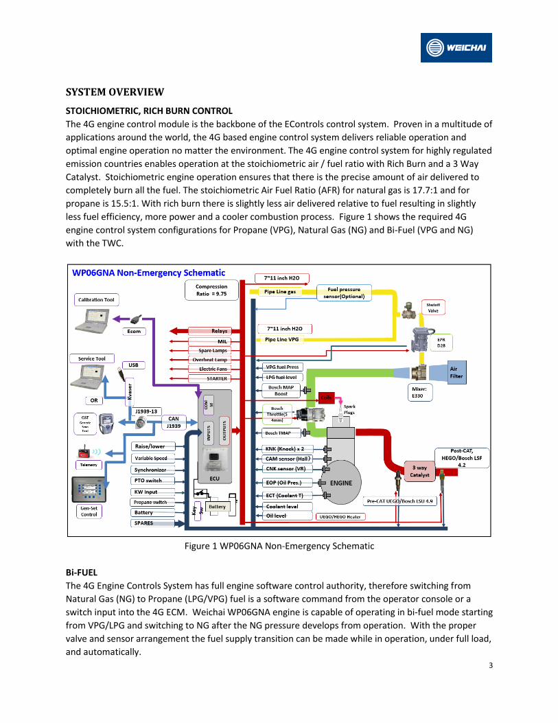
SYSTEM OVERVIEW
STOICHIOMETRIC, RICH BURN CONTROL
The 4G engine control module is the backbone of the EControls control system. Proven in a multitude of
applications around the world, the 4G based engine control system delivers reliable operation and
optimal engine operation no matter the environment. The 4G engine control system for highly regulated
emission countries enables operation at the stoichiometric air / fuel ratio with Rich Burn and a 3 Way
Catalyst. Stoichiometric engine operation ensures that there is the precise amount of air delivered to
completely burn all the fuel. The stoichiometric Air Fuel Ratio (AFR) for natural gas is 17.7:1 and for
propane is 15.5:1. With rich burn there is slightly less air delivered relative to fuel resulting in slightly
less fuel efficiency, more power and a cooler combustion process. Figure 1 shows the required 4G
engine control system configurations for Propane (VPG), Natural Gas (NG) and Bi-Fuel (VPG and NG)
with the TWC.
Figure 1 WP06GNA Non-Emergency Schematic
Bi-FUEL
The 4G Engine Controls System has full engine software control authority, therefore switching from
Natural Gas (NG) to Propane (LPG/VPG) fuel is a software command from the operator console or a
switch input into the 4G ECM. Weichai WP06GNA engine is capable of operating in bi-fuel mode starting
from VPG/LPG and switching to NG after the NG pressure develops from operation. With the proper
valve and sensor arrangement the fuel supply transition can be made while in operation, under full load,
and automatically.

4
NG/VPG is WP06GNA standard configuration. With added on option, WP06GNA can also support LPG,
manual or automatic switching.
TELEMATICS SUPPORT
Hardware and software capability exist in the full authority 4G control system to send and receive CAN
communication files in a structured message format. The input and output file structure and variable
content need to be defined by the customer and implemented by WEICHAI. There will be an
engineering change associated with setting up the file structures and debugging the communications
with the telematics module. Equipment and technical support is available from Weichai.
Diagnostic Messages
The 4G engine control system contains a highly configurable diagnostic list that can be tailored to each
application’s specific needs using the calibration spreadsheet. With each available P-code listed along
with the short-name description. Note that not all DTCs necessarily apply to every application.
ECM: Engine Control Module: 4G 90 pin
The ECM is full authority, by this we mean it includes the ignition and air/fuel ratio control, contains all
the I/O to interface the engine with the application and has a complete set of diagnostics. By
implementing all functions in one box the overall system complexity is reduced as is the total system
cost.
Some of features included in the ECMs are, lean burn or stoichiometric combustion control, continuous
fuel injection control or standard digital injectors, ignition control electronic boost control for
turbochargers – VGT or wastegate, drive-by-wire throttle control, oxygen sensor based closed-loop
air/fuel ratio control (wide band (UEGOs) or switching (HEGOs)), adaptive spark and fuel control, EGR
control, transmission / engine coordination, speed control/governing (idle, max speed, all-speed, cruise
control) and vehicle network interface systems (CAN, J1708, J1850, Ford SCP).
DEPR: Direct Acting Electronic Pressure Regulator
Our fuel control device is referred to as a Direct Acting Electronic Pressure Regulator or D-EPR shown in
Figure 2. Its benefits to our customers and the end customer are:

5
Figure 2 Direct Acting Electronic Pressure Regulator (DEPR)
- It is a continuous fuel flow device. This allows the most homogeneous mixture of air and fuel to the
engine yielding optimum combustion with minimum emissions and maximum fuel economy. - It operates on low pressure fuel from 6 to 20 inches of water of inlet pressure, no pressure
intensification system required. - It does not wear in the case or dry fuels (NG) and it does not stick or clog due to heavy hydrocarbons
or waxes found in LPG. - It is fast and accurate, providing precise air/flow ratio control during transients (or load acceptance).
The DEPR is a single-stage microprocessor based electromechanical fuel pressure regulator that
incorporates a high speed actuator. It communicates with the Engine Control Module (ECM) over a
Controller Area Network (CAN) link, receiving fuel pressure commands and broadcasting DEPR operating
parameters back to the ECM. The DEPR can regulate fuel pressure between +/- 17 inches of water
column above the Mixer air inlet pressure, providing sufficient control authority to stall an engine either
rich or lean. When the DEPR receives an output pressure command from the ECM, the valve is internally
driven to attain targeted fuel pressure, the DEPR then closes the loop internally using a built in fuel
pressure sensor to maintain target fuel pressure/fuel flow rate, until another external command from
the ECM is received.
6
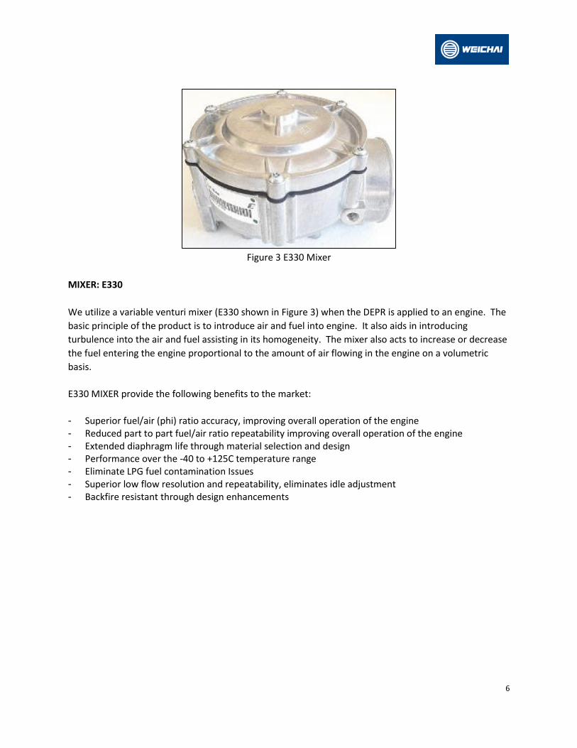
Figure 3 E330 Mixer
MIXER: E330
We utilize a variable venturi mixer (E330 shown in Figure 3) when the DEPR is applied to an engine. The
basic principle of the product is to introduce air and fuel into engine. It also aids in introducing
turbulence into the air and fuel assisting in its homogeneity. The mixer also acts to increase or decrease
the fuel entering the engine proportional to the amount of air flowing in the engine on a volumetric
basis.
E330 MIXER provide the following benefits to the market:
- Superior fuel/air (phi) ratio accuracy, improving overall operation of the engine - Reduced part to part fuel/air ratio repeatability improving overall operation of the engine - Extended diaphragm life through material selection and design - Performance over the -40 to +125C temperature range - Eliminate LPG fuel contamination Issues - Superior low flow resolution and repeatability, eliminates idle adjustment - Backfire resistant through design enhancements

7
HEAVY-DUTY DUAL STAGE REGULATOR (DSR)
The heavy-duty dual stage regulator vaporizes liquid propane to gaseous form and also regulates the
fuel pressure to meet the fuel pressure requirement.
Figure 4 Heavy-Duty Dual Stage Regulator
The HD DSR (shown in Figure 4) is a two stage fully mechanical regulator that is available in NG and LPG
configurations. The DSR is normally open with a positive outlet pressure and must be used with fuel
lock-off upstream to prevent fuel flow when the engine is not cranking or running. The HD DSR is
connected to the DEPR, by a low pressure flexible hose. It also has a reference port that is connected to
the fuel / air mixer for turbo-charged applications.
Key features of the HD Dual Stage Regulator are:
- Full mechanical pressure regulation - Can be engine or chassis mounted (vibration requirements are defined on the installation drawing). - Flows 250 kW at the rate inlet pressure. - 1725 kPa inlet regulated down to a 3.5 kPa outlet pressure
8
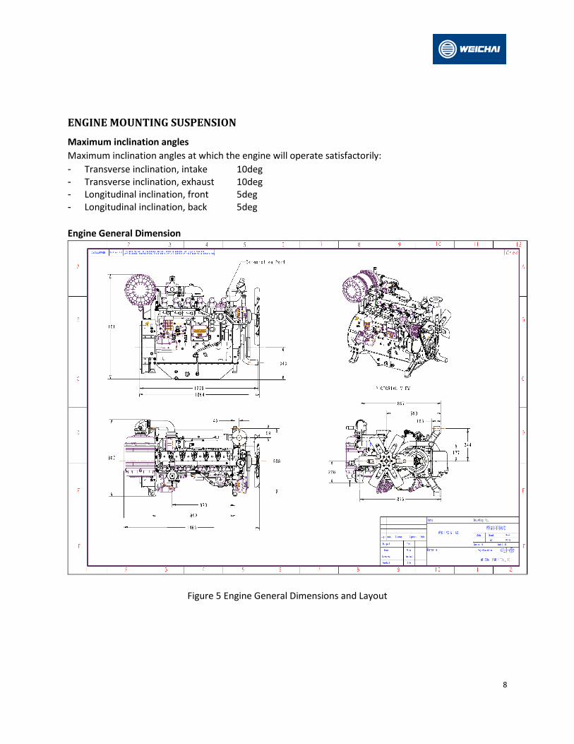
ENGINE MOUNTING SUSPENSION
Maximum inclination angles
Maximum inclination angles at which the engine will operate satisfactorily:
- Transverse inclination, intake 10deg - Transverse inclination, exhaust 10deg - Longitudinal inclination, front 5deg - Longitudinal inclination, back 5deg
Engine General Dimension
Figure 5 Engine General Dimensions and Layout
9
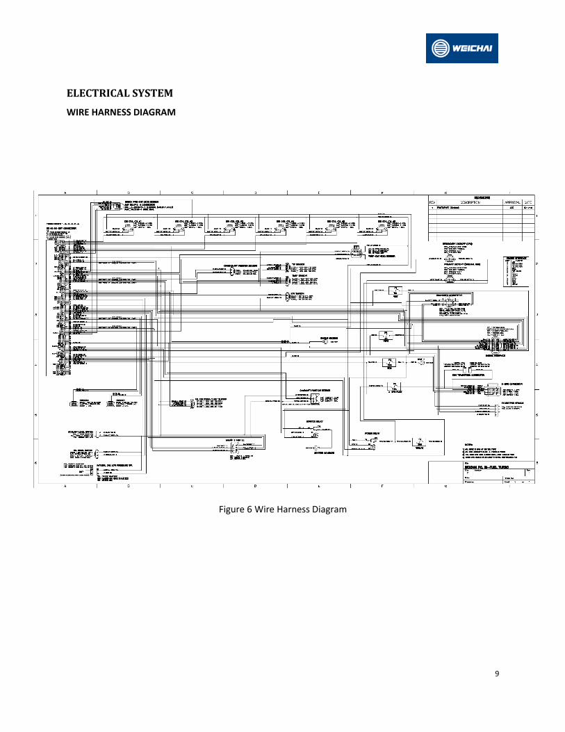
ELECTRICAL SYSTEM
WIRE HARNESS DIAGRAM
Figure 6 Wire Harness Diagram
10
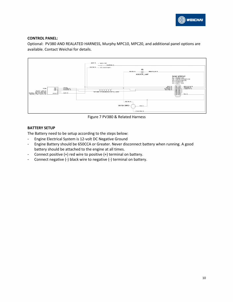
CONTROL PANEL:
Optional: PV380 AND REALATED HARNESS, Murphy MPC10, MPC20, and additional panel options are
available. Contact Weichai for details.
Figure 7 PV380 & Related Harness
BATTERY SETUP
The Battery need to be setup according to the steps below:
- Engine Electrical System is 12-volt DC Negative Ground - Engine Battery should be 650CCA or Greater. Never disconnect battery when running. A good
battery should be attached to the engine at all times. - Connect positive (+) red wire to positive (+) terminal on battery. - Connect negative (-) black wire to negative (-) terminal on battery.

11
CANBUS J1939 INTERFACE CONNECTING WITH ZTR TELEMATICS
Figure 8 CANBUS J1939 Interface Connection with ZTR Telematics
INTAKE AIR SYSTEM
The intake system should be sealed between the mixer inlet and the filter. Proper clamps should be
used to ensure unfiltered air is not drawn into the system. Use piping with minimum diameter equal to
mixer inlet. When in an enclosure it can sometimes be necessary to use an externally mounted filter. It
can be beneficial to engine life and performance to draw in air from the coolest location possible

12
Figure 9 Intake Air System
Weichai engine uses a closed crankcase ventilation system as shown in Figure 10. The breather
separates the crankcase oil/gas mixture and lets the oil return to the sump and sends the gas into the
intake system.
Figure 10 Closed Crankcase Ventilation System
13
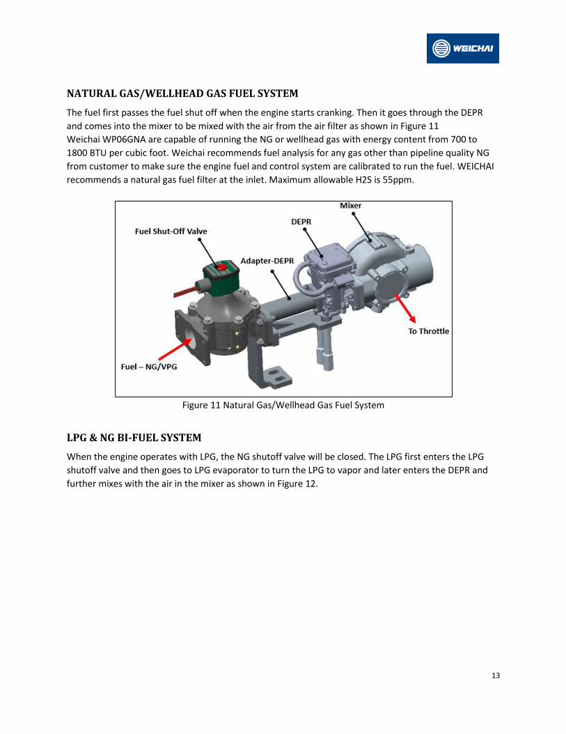
NATURAL GAS/WELLHEAD GAS FUEL SYSTEM
The fuel first passes the fuel shut off when the engine starts cranking. Then it goes through the DEPR
and comes into the mixer to be mixed with the air from the air filter as shown in Figure 11
Weichai WP06GNA are capable of running the NG or wellhead gas with energy content from 700 to
1800 BTU per cubic foot. Weichai recommends fuel analysis for any gas other than pipeline quality NG
from customer to make sure the engine fuel and control system are calibrated to run the fuel. WEICHAI
recommends a natural gas fuel filter at the inlet. Maximum allowable H2S is 55ppm.
Figure 11 Natural Gas/Wellhead Gas Fuel System
LPG & NG BI-FUEL SYSTEM
When the engine operates with LPG, the NG shutoff valve will be closed. The LPG first enters the LPG
shutoff valve and then goes to LPG evaporator to turn the LPG to vapor and later enters the DEPR and
further mixes with the air in the mixer as shown in Figure 12.

14
Figure 12 LPG & NG Bi-Fuel System
VPG & NG BI-FUEL SYSTEM: Similar to LPG & NG Bi-fuel system, the engine can also operate with VPG &
NG Bi-Fuel combination. The NG shutoff valve will be closed when the propane gas is being used for
running the engine. The propane gas flows through VPG shutoff valve to the DEPR and further mixes
with the air in the mixer. The changes compared to LPG bi-fuel system are change in shut-off valve and
no LPG evaporator requirement.
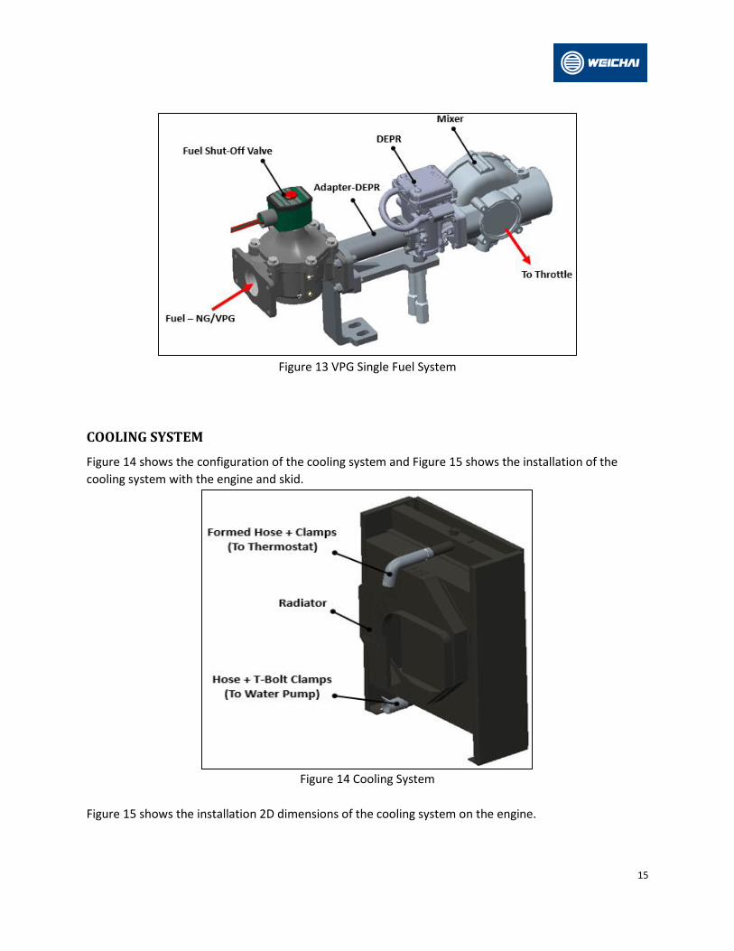
VPG SINGLE FUEL SYSTEM
For single VPG fuel application, the same shut-off valve as NG is used to turn on or off the fuel, but the
shut-off valve needs to be connected with the secondary fuel connector from the harness as Secondary
Lockoff (LPG) only.
15
Figure 13 VPG Single Fuel System
COOLING SYSTEM
Figure 14 shows the configuration of the cooling system and Figure 15 shows the installation of the
cooling system with the engine and skid.
Figure 14 Cooling System
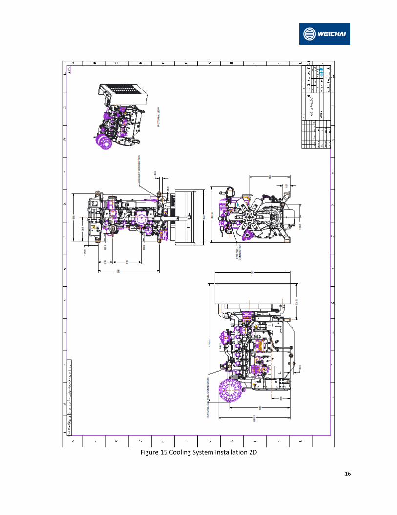
Figure 15 shows the installation 2D dimensions of the cooling system on the engine.
16
Figure 15 Cooling System Installation 2D
17
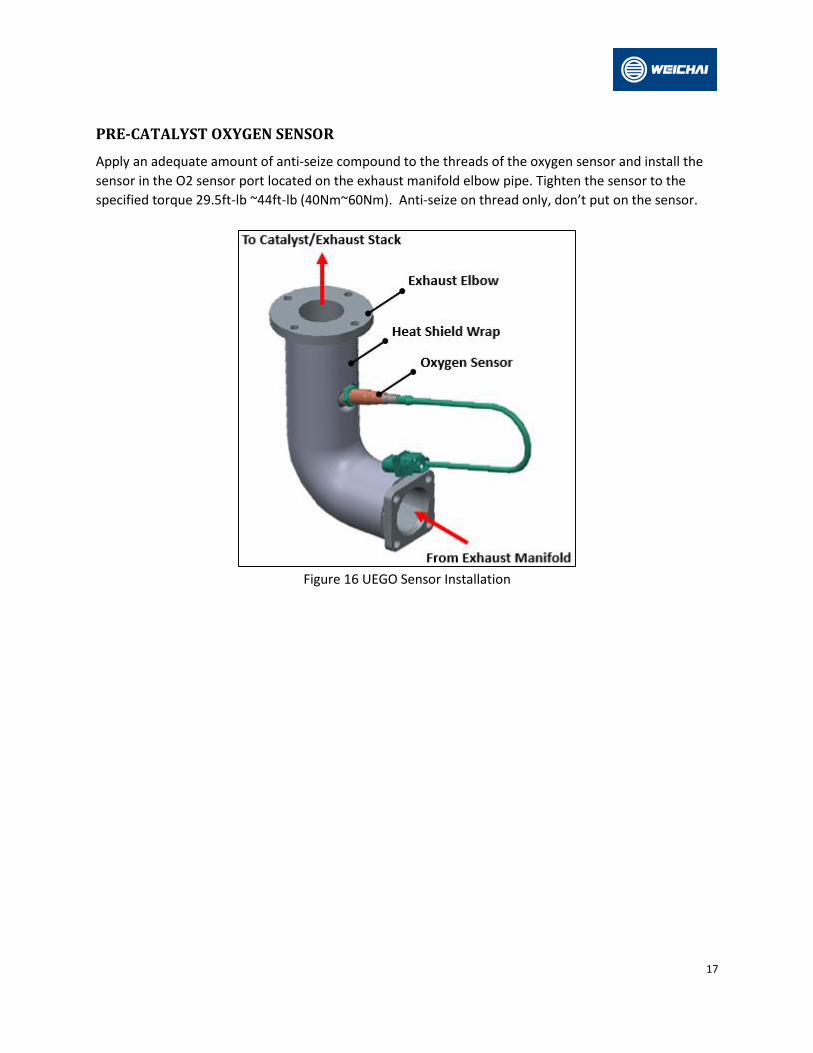
PRE-CATALYST OXYGEN SENSOR
Apply an adequate amount of anti-seize compound to the threads of the oxygen sensor and install the
sensor in the O2 sensor port located on the exhaust manifold elbow pipe. Tighten the sensor to the
specified torque 29.5ft-lb ~44ft-lb (40Nm~60Nm). Anti-seize on thread only, don’t put on the sensor.
Figure 16 UEGO Sensor Installation
18
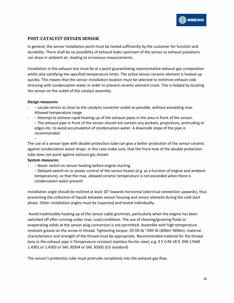
POST-CATALYST OXYGEN SENSOR
In general, the sensor installation point must be tested sufficiently by the customer for function and
durability. There shall be no possibility of exhaust leaks upstream of the sensor as exhaust pulsations
can draw in ambient air, leading to erroneous measurements.
Installation in the exhaust line must be at a point guaranteeing representative exhaust gas composition
whilst also satisfying the specified temperature limits. The active sensor ceramic element is heated up
quickly. This means that the sensor installation location must be selected to minimize exhaust-side
stressing with condensation water in order to prevent ceramic element crack. This is helped by locating
the sensor on the outlet of the catalyst assembly.
Design measures:
- − Locate sensor as close to the catalytic converter outlet as possible, without exceeding max. Allowed temperature range
- − Attempt to achieve rapid heating-up of the exhaust pipes in the area in front of the sensor. − The exhaust pipe in front of the sensor should not contain any pockets, projections, protruding or edges etc. to avoid accumulation of condensation water. A downside slope of the pipe is recommended. −
The use of a sensor type with double protection tube can give a better protection of the sensor ceramic
against condensation water drops. In this case make sure, that the front hole of the double protection
tube does not point against exhaust gas stream
System measures:
- − Never switch on sensor heating before engine starting − Delayed switch-on or power control of the sensor heater (e.g. as a function of engine and ambient temperature), so that the max. allowed ceramic temperature is not exceeded when there is condensation water present
Installation angle should be inclined at least 10° towards horizontal (electrical connection upwards), thus
preventing the collection of liquids between sensor housing and sensor element during the cold start
phase. Other installation angles must be inspected and tested individually.
Avoid inadmissible heating up of the sensor cable grommet, particularly when the engine has been
switched off after running under max. Load conditions. The use of cleaning/greasing fluids or
evaporating solids at the sensor plug connection is not permitted. Assemble with high temperature
resistant grease on the screw-in thread. Tightening torque: 29.5ft-lb ~44ft-lb (40Nm~60Nm). material
characteristics and strength of the thread must be appropriate. Recommended material for the thread
boss in the exhaust pipe is Temperature resistant stainless ferritic steel, e.g. X 5 CrNi 18 9, DIN 17440
1.4301 or 1.4303 or SAE 30304 or SAE 30305 (US standard)
The sensor’s protection tube must protrude completely into the exhaust-gas flow.

19
Figure 17 TWC and Post HEGO Sensor Installation
There is to be no possibility of the sensor protection tube contacting the opposite side of the exhaust
pipe. A waterproof electrical connector’s version is required.
The sensor must be covered when underseal (wax, tar, paint etc.) or spray oil is applied to the vehicle.
The influence of contamination which enters the exhaust gas through the intake air or as a result of fuel,
oil, sealing materials etc., and thus reaches the sensor is application specific and must be determined by
customer tests.
The sensor must not be exposed to strong mechanical shocks (e.g. while the sensor is installed).
Otherwise the sensor element may crack without visible damage at the sensor housing.
For physical reasons the sensor needs ambient air at its reference gas side. Replacement of the air
volume inside the sensor must be guaranteed by a sufficient air permeability of the wires and the
connectors between sensor and ECU. The breathability should be higher than 1 ml/minute at a test
pressure of 100mbar.
Underfloor installation of the sensor remote from the engine requires an additional check of the
following points
- positioning of the sensor with respect to stone impact hazard - positioning and fixing of cable and connector with respect to mechanical damage, cable bending
stress and thermal stress.
The sensor cable must be routed so that it is free of bends, mechanical tension, and chafing points
considering the movement of the exhaust system in relation to the vehicle body. The cable and
connector should not be subjected to excessive temperatures that could cause damage.
Additional instructions for the installation downstream the catalytic converter
- Between catalyst and sensor location absolute gas tightness of the exhaust system must be ensured. - When the sensor is installed in the exhaust pipe there should be no detachable connections
between catalytic converter and sensor (e.g. flange, clamp-screw joint).
20
- In order to protect the active sensor ceramic against condensation water from the exhaust gas side the sensor heater voltage must be power controlled after cold start of the engine. During the condensation water phase, the ceramic temperature should be kept at approx. 302degF ~572degF (150°C-300°C). The corresponding control parameter must be determined according to application.
- The sensor should be mounted as close to the outlet of the catalytic converter as possible without exceeding sensor maximum temperatures.
- The sensor should be mounted as far from the exhaust pipe outlet as possible to avoid dilution from ambient air. Minimum distance between sensor and exhaust outlet should be 15.7 inches (400 mm).

21
CATALYTIC CONVERTER
A very important component in a low emission engine is the catalytic converter. Weichai Engines use a
TWC converter. For this type of catalytic converter to work properly, the following two criteria must be
met:
- The air-to-fuel ratio must oscillate between rich and lean. - The catalyst substrate (also known as a “brick,” located inside the converter shell) must be kept hot.
Strict compliance with these provisions, conditions, and operating limits for catalytic converters must be
maintained. If these parameters cannot be met or are not known, additional engineering and validation
are required.
Operation
- The continuous operating exhaust gas temperature must be between 1112degF (600°C) and 1562degF (850°C).
- The Product installer shall take necessary precautions to accommodate shell skin temperatures - up to 1202degF (650°C). - System backpressure must remain with +/- 5% of nominal conditions. - Engine misfires and exhaust stream containments are not permissible.
Vibration
- Vibration isolation must be provided between the engine and the TWC - Vibration isolation must be provided between the Product and the chassis. - Vibration acceleration loads shall not exceed 10g. Installation
- Product shall not support mounting loads from adjacent components. - Product must be mounted within +/- 10° of horizontal. Any other orientation must be approved - by the manufacturer. - Product must be supported at a minimum of two mounting locations. - Installer shall ensure mounting hardware, such as fasteners, is sufficient for the application. - Manufacturer recommends use of graphite gaskets for flanged joints. - Heat shields must be reviewed by the manufacturer. - Product cannot be used in corrosive environments (i.e. salt water).
Mounting the catalytic converter in the proper location will control the substrate temperature. To
quickly heat up the catalyst and to ensure an effective operating temperature, the center of the
substrate must be located a minimum of 30 inches (762mm) downstream of the exhaust manifold
flange. This measurement is made along the length of the exhaust pipe and must take all bends and
curves into consideration. The Max distance allowed downstream of the exhaust manifold flange is
36inches (914mm).
22
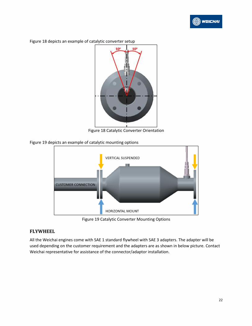
Figure 18 depicts an example of catalytic converter setup
Figure 18 Catalytic Converter Orientation
Figure 19 depicts an example of catalytic mounting options
Figure 19 Catalytic Converter Mounting Options
FLYWHEEL
All the Weichai engines come with SAE 1 standard flywheel with SAE 3 adapters. The adapter will be
used depending on the customer requirement and the adapters are as shown in below picture. Contact
Weichai representative for assistance of the connector/adaptor installation.

23
Figure 20 Flywheel and Flywheel housing
ADJUSTABLE PARAMETERS ON NON-COMMERCIAL FUELS
This engine has been certified by the US EPA to be operated on pipeline quality commercial Natural Gas
fuels as well as non-commercial Natural gas fuels including Well Head Gas and propane.
The ECM has the ability to adjust for in-service fuel specific gravity, and stoich AFR. Calibration is
completed with “standard” and “actual” values set according to fuel samples in test cell. “Actual” values
adjusted post calibration to match in-service fuel, effectively re-zeroing the closed loop fuel control.
Fuel System is non-adjustable and it can compensate for fuel LHV from 700 to 1800 BTU/SCF. When
running on propane, the control system has a separate calibration activated by a fuel switch (shown in
Figure 21) that can switch between fuels from 700 to 1800 BTU/SCF LHV to higher than 1800 BTU/SCF
fuels up to commercial LPG. The default setting is for fuels with heating values from 700-1800 BTU/SCF,
the other position “LPG” is for fuels with more than 1800 BTU/SCF LHV and LPG.
Figure 21 Fuel Switch for Different Fuel BTU Ranges

24
WARNING: ADJUSTMENTS MADE TO THE FUEL DELIVERY SYSTEM WILL INFLUENCE THE TAILPIPE
EXHAUST EMISSIONS. IT IS THE OWNER/OPERATOR’S RESPONSIBILITY TO TEST THE SPECIFIC FUEL TYPE
AT EACH SITE OF INSTALLATION AND DETERMINE THE CORRECT FUEL SYSTEM SETTINGS
THIS ENGINE IS CERTIFIED TO OPERATE IN APPLICATIONS USING NONCOMMERCIAL FUEL.
MALADJUSTMENT OF THE ENGINE IS A VIOLATION OF FEDERAL LAW SUBJECT TO CIVIL PENALTY.
Fuel Pressure
Fuel Pressure need to be checked for the first start as in the Table 1
Table 1 EPR inlet pressure specification
Maximum EPR Rated Pressure kPa 6.9
Maximum Running pressure to Electronic Pressure Regulator (EPR) kPa 2.7

25
ABBREVIATION DEFINITION
ABBREVIATION DEFINITION
DEPR Direct acting Electronic Pressure Regulator
DSR Dual Stage Regulator
DST Diagnostic Service Tool
ECM Engine Control Module
LPG Liquid Propane Gas
NG Natural Gas
TWC Three Way Catalyst
VPG Vapor Propane Gas