Embed Size (px)
Citation preview
E-55-01
Mar 2019
WATER SUPPLIES DEPARTMENT
STANDARD SPECIFICATION E-55-01
HIGH VOLTAGE MOTORS OF 3.3 kV AND ABOVE
- 2 - E-55-01
Mar 2019
WATER SUPPLIES DEPARTMENT
STANDARD SPECIFICATION E-55-01
HIGH VOLTAGE MOTORS OF 3.3 kV AND ABOVE
1 GENERAL
1.1 Scope
This specification covers the design, manufacture, testing and delivery of high voltage
squirrel cage induction motors with rated voltages at 3.3 kV, 6.6 kV or 11 kV suitable
for driving the centrifugal water pumps specified in Water Supplies Department(WSD)
Standard Specification M-01-01.
1.2 Waterworks Standard Specifications
The motor and auxiliary equipment shall comply with this Specification and WSD
Standard Specification E-00-01 "Electrical Equipment - General". This Specification
shall take precedence in case if there is any discrepancy between the two standard
specifications.
The drawings and manuals supplied with the equipment shall comply with the
following standard specifications issued by the WSD:
(a) EM-90-01 Drawing for Mechanical, Electrical and Instrumentation Plant and
Equipment
(b) EM-90-02 Instruction Manual for Mechanical, Electrical and Instrumentation
Plant and Equipment
1.3 Standards
Equipment shall comply with the latest version of the relevant international Standards
and Codes of Practice. The following Standards, in particular, shall apply where
appropriate:
(a) IEC 60034 Rotating electrical machines
(b) IEC 60085 Electrical insulation – Thermal evaluation and designation
(c) IEC 60751 Industrial platinum resistance thermometer sensors
(d) ISO 281 Rolling bearings – Dynamic load ratings and rating life
1.4 Type Test Certification
Type tests shall have been performed on equipment which is essentially similar to that
being supplied.
- 3 - E-55-01
Mar 2019
Type test certificates of short circuit rating shall be issued by the Association of Short
Circuit Testing Authorities UK (ASTA) or other equivalent internationally recognised
authority. Type tests shall be carried out in accordance with the requirements of the
relevant Standards.
The type test requirements for equipment are listed as follows:
(a) Motor winding insulation level tests (Clause 3.4)
(b) Motor main cable box fault withstand type test (Clause 3.11.2)
Complete details of the type test reports containing the test arrangement and test
results shall be submitted to supplement the test certificates when requested. The
equipment supplied shall be strictly in accordance with the design of the approved
type tested equipment.
2 PERFORMANCE REQUIREMENTS
2.1 Technical Particulars
(a) Type : High energy efficient squirrel cage
induction motor with rated load
efficiency as follows:
Rated Output Minimum Efficiency
less than 500 kW 95.0 %
500 kW – 990 kW 95.5 %
1,000 kW and Above 96.0%
(b) Standards : IEC 60034, IEC 60072 and other
relevant international standards
(c) Duty Rating : Maximum continuous rating (MCR),
S1 duty to IEC 60034-1
(d) Insulation : Class F design with temperature rise
not exceeding the limit applicable to
Class B in IEC 60034-1
(e) Maximum Speed : 1,500 rpm at 50Hz
(f) Noise Level : Mean sound power level (Lw) in dB(A)
for airborne noise emitted by motor not
exceeding the limits given in IEC
60034-9.
(g) Vibration Level : Grade A of IEC 60034-14
- 4 - E-55-01
Mar 2019
(h) Uncorrected Power Factor : 0.83 minimum at duty point without
negative tolerance
2.2 Site Operating Conditions
(a) Altitude of site above sea level : not greater than 1,000 m
(b) Ambient temperature : Peak over any 4 hours : 40C
Average over 24 hours : 35C
Minimum : 0C
(c) Relative humidity : Up to 98%
2.3 Electricity Supply
(a) Mains supply : 11 kV, 6.6 kV or 3.3 kV 3 phase, 50 Hz
3 wire solidly earthed neutral system
(b) Normal limits of voltage fluctuation : +10% -2½ %
(c) Normal limits of frequency variation : 2%
(d) Auxiliary power supply : 220V 10% single phase 50 Hz and
24V 15% d.c.
2.4 Starting Performance
Direct-on-line starting current at rated voltage shall not exceed 5 times the full load
current for motors of 500 kW and above, and not exceed 6 times the full load current
for motors below 500 kW.
The motor shall be designed to permit at least three starts per hour equally spaced
during normal running conditions. The motor shall also be suitable for two starts in
succession followed by a 30 minutes interval before attempting another starting
sequence.
The minimum voltage at motor windings at starting shall be 80% of nominal value for
direct-on-line started motor, and 50% for motor with auto-transformer starter.
The starting (run-up) torque characteristics of motor at minimum voltage shall be
adequate for driving the load to full running speed under the most arduous conditions
specified. The accelerating torque at any speed up to the peak torque point shall be not
less than 10% of the motor rated full load torque.
Direct-on-line started motor with 80% rated voltage across its winding shall run to
90% of its synchronous speed within 4 seconds. Motor with assisted starting, at 50%
rated voltage across its winding and without changing to its final connection, shall run
to at least 90% of its synchronous speed within 10 seconds. During such starting
- 5 - E-55-01
Mar 2019
intervals, the pump discharge valve shall open in its normal manner.
The pull-out torque of motors shall be not less than 200% of its full load torque unless
otherwise approved.
2.5 Running
Notwithstanding the voltage fluctuation specified in Clause 2.3 above, motors shall be
capable of operating continuously at any voltage in the range 90-110% of its rated
voltage.
Motors shall be capable of continuous operation at 75% of its rated voltage at 50 Hz
for a period of 5 minutes without excessive heating.
2.6 Transient Recovery
Motors shall be capable of recovering normal operation in the event of a system
disturbance causing temporary loss of supply voltage for a period of up to 0.2 second
(fault clearance time) followed by a sudden restoration to 80% of its rated voltage.
At this voltage the motors shall then be capable of accelerating to ultimate recovery
under the most arduous load conditions, e.g. fully open pump discharge valve, etc.
2.7 Power Rating
The rated motor power output shall be not less than 120% for fresh water pumpset and
115% for salt water pumpset of the maximum power absorbed by the pump over the
entire pump operating range specified. The foregoing power margin shall not be
reduced by any factors such as tolerances of pumpset performance or accuracy of test
equipment.
3 DESIGN AND CONSTRUCTION
3.1 Enclosure
The enclosure shall have a degree of protection of IP 22 (drip proof) or IP 55 (totally
enclosed) to IEC 60034-5. Dimensions and frame number of motors shall comply with
IEC 60072. Motors of size less than 1,000kW shall be protected to IP 55.
Motors of the same capacity and speed shall be interchangeable.
Motors shall be provided with suitable means of breathing and draining to prevent
accumulation of water from condensation.
The motors shall have cast iron casings. Acoustic enclosure shall not be used.
The motor frame shall be designed to facilitate easy removal of rotor assembly and to
permit access from both motor ends for cleaning and rewinding of the stator winding
and replacement of the complete stator core assembly.
- 6 - E-55-01
Mar 2019
For motors to be installed at a location with the non driving end (NDE) bearing higher
than 2,000 mm from the floor, a fixed motor platform complete with guardrails and
ladder shall be provided for the safe access to the top of the motor. The platform shall
be detachable to allow the safe and unimpeded removal and re-siting of the motor.
The finished colour of the motor shall be the same as the driven equipment.
3.2 Ventilation and Cooling
Unless otherwise specified, motors of size 1,000 kW or above shall be fitted with
individual outlet air duct to IEC 60034-6, method of cooling IC2A1. Smaller motors
shall be designed for method of cooling IC411, with self-circulation air as coolant.
The motor air inlet shall normally be arranged to draw ventilating air directly from the
surrounding. The inlet shall be equipped with a removable and washable air filter.
The motor fan for outlet air shall be designed so that at the worst operating condition
and rated output, the actual operating temperature of the stator winding will not
exceed the value specified for Class B insulation and the external surface temperature
of parts liable to be contacted with will not be more than 65C at 40C ambient.
The motor ventilating fan shall be directly driven by the motor itself viz. no auxiliary
power supply required. The fan shall be designed to take into account the air
resistance of the air ducting and the back pressure at the discharge outlet equivalent to
a wind velocity of 10 m/sec. blowing directly against the exhaust air outlet grill.
Design calculation of the air ducts shall be submitted for assessment.
Ducts shall be fabricated with 1.2mm thick grade 316 stainless steel sheet or hot-dip
galvanized steel sheet to BS EN 10143 Grade 22 and of thickness not less than 1.5
mm. The ducts shall be so constructed that the pressure losses due to eddies or
vortices are minimized and no noise or vibration is created or transmitted. Face panels
shall be stiffened and creased to prevent "drumming".
All ductwork shall be secured by hangers, brackets or other appropriate means of
support. All mild steel components shall be hot dip galvanized.
Provisions shall be made in the design to prevent water or condensate getting into the
winding through the ventilation ducts. An accessible drain cock shall be provided at
the lowest point of the ducting for draining of condensate as and when necessary.
A flexible coupling shall be provided between the motor and the ducting.
Access/maintenance openings shall be provided at suitable positions to facilitate
inspection and cleansing of the interior.
The air velocity in ducts shall not exceed 10 m/sec.
3.3 Thermal Insulation and Characteristic
- 7 - E-55-01
Mar 2019
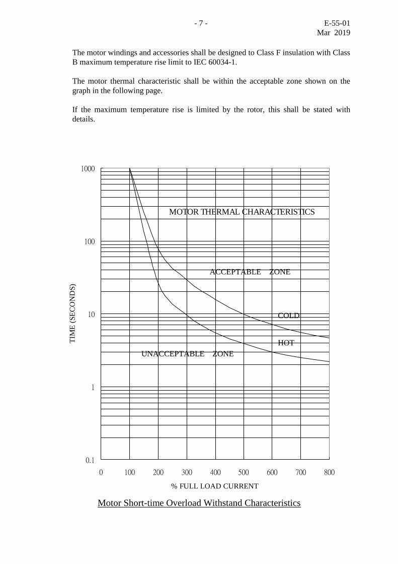
The motor windings and accessories shall be designed to Class F insulation with Class
B maximum temperature rise limit to IEC 60034-1.
The motor thermal characteristic shall be within the acceptable zone shown on the
graph in the following page.
If the maximum temperature rise is limited by the rotor, this shall be stated with
details.
MOTOR THERMAL CHARACTERISTICS
0.1
1
10
100
1000
0 100 200 300 400 500 600 700 800
% FULL LOAD CURRENT
TIM
E (
SE
CO
ND
S)
Motor Short-time Overload Withstand Characteristics
UNACCEPTABLE ZONE
ACCEPTABLE ZONE
COLD
HOT
- 8 - E-55-01
Mar 2019
3.4 Motor Stator and Winding
The stator winding shall be designed for a minimum life of 25 years of service at rated
load and voltage.
The motor winding insulation shall withstand the voltage stress caused by switching
of an oil circuit-breaker, SF6 circuit-breaker, vacuum circuit-breaker or vacuum
contactor as motor starter. The vacuum interruptors will have a level of current
chopping of 5A, a rate of rise of restriking voltage up to 0.2 kV/s and a peak
restriking voltage of 229% of its rated line voltage.
Motors shall be designed to permit high voltage tests in accordance with IEC 60034-1
to be conducted after erection on site.
End windings shall be rigidly braced to prevent their movement at the specified
service duty. Semi-resin mica tape and hyper-sealing tape shall be used for insulation
of winding overhang and jumpers. Heat shrinkable insulating material shall not be
used as Class F motor insulation. The winding overhang shall be accessible for
cleaning.
The stator winding shall be insulated by vacuum pressure impregnation (VPI) process.
Windings shall have a surface treatment to prevent deterioration due to adverse
environmental conditions and for corona shield.
Winding coils shall be of preformed type. Stator slots shall be of open type to
facilitate easy insertion of replacement windings.
Laminated type magnetic slot wedges shall not be used. If the manufacturer proposes
to use other type of magnetic wedges, the resulting change in performance as
compared with non-magnetic slot wedges shall be submitted for acceptance.
Type test reports for loss tangent to BS EN 50209 and high voltage impulse test to
IEC 60034-15 shall be provided to substantiate the winding insulation design.
Silicone rubber insulated cables and fiberglass tapes for cable fixing shall be used
between the stator windings and cable terminals inside the motor enclosure.
Stator winding details including the embedded resistance temperature detectors (RTD)
shall be provided as detailed in WSD Standard Specification EM-90-01 and
EM-90-02. Sufficient data and drawings shall be provided to enable stator coils to be
ordered in future. Instructions for coil impregnation and curing, stator rewinding,
impregnation and dry-out shall be supplied.
3.5 Rotor
3.5.1 Type
The rotor shall be of cage type with copper/copper alloy winding.
- 9 - E-55-01
Mar 2019
3.5.2 Vibration Level
The limits of vibration shall comply with Grade A of IEC 60034-14.
3.5.3 Dynamic Balancing
The rotor shall be dynamically balanced at its rated speed or a speed not less than 600
rpm whichever is the greater to confirm that vibration levels are within the specified
limit.
Means and access for fixing balancing weights in situ shall be provided at both ends
of the rotor without the need to dismantle the motor for balancing on site.
3.5.4 Insulation Against Stray Current
For motors of 750 kW and above or where the induced shaft voltage exceeds 0.15V,
an insulated bearing arrangement shall be provided. Where such provision is made, all
motor bearings shall be insulated from the stator frame and a removable earth bonding
link shall be provided at the driving end to facilitate insulation tests.
Oil and water pipes etc. where fitted shall be insulated to prevent a current return path
through the bearings of the motor shaft. Care shall be taken to ensure that any
insulation is not short-circuited by the application of electrically conducting paints or
fixing clips. Laminated fibre-glass washers and sleeves shall be used for bearing
insulation.
3.5.5 Rotor Removal
For vertically mounted motor, the rotor and the shaft shall be capable of being lifted
vertically from the stator without the need of removing the half coupling.
When the motor shaft is not located axially by its own bearings, it shall be
permanently marked to indicate its normal running position and the extent of float
permissible in either direction.
3.5.6 Half Coupling
Coupling which do not require regular application of lubricant during operation shall
be supplied.
3.6 Radial Air Gap
The nominal air gap between stator and rotor of motors shall take into consideration
all causes of eccentric positioning of the rotor in the stator bore, (e.g. bearing
clearance, clearances between bearing bracket spigots, deflection of shaft due to rotor
weight and loading external to the shaft) and the deflection of the shaft due to
unbalanced magnetic pull.
For motors with ball and/or roller bearings, the nominal air gap shall be not less than
- 10 - E-55-01
Mar 2019
the appropriate value shown in Table 1 below.
For motors with plain (sleeve) type bearings, the nominal air gap shall be 1.5 times the
appropriate value shown in Table 1.
Where the core length L of a motor is more than 1.75 times the rotor diameter D, the
nominal air gap, shall be L times the appropriate value shown in Table 1.
1.75D
Table 1 - Nominal Radial Air Gap
Number of Poles
Nominal Radial Air Gap (mm)
D = up to 750 mm D = over 750 mm
4
6 or more
0.07 + D
500
0.13 + D
800
1.7
1.2
Note : D is the rotor diameter in mm.
Provision shall be made for checking the radial air gaps at each end of the motor
having a plain (sleeve) type bearing.
3.7 Bearings
3.7.1 General
Bearings shall be exclusively of metric sizes.
Bearings for horizontal motors shall be provided in accordance with Table 2 below.
Table 2 - Type of Bearing (Horizontal Motor)
Number of Poles Motor Rating Type of Bearing
for both DE and NDE
4
6 or more
Above 500 kW
Up to 500 kW
Above 750 kW
Up to 750 kW
Plain
Rolling
Plain
Rolling
For vertical motors of rating 1,000 kW or above, plain type thrust and guide bearings
shall be provided at the non-drive end.
- 11 - E-55-01
Mar 2019
The motor manufacturer shall examine the external axial and radial load imposed
from the shaft and the driven device in the selection of type of bearing to be used.
Where damage is likely to occur to rolling bearings due to thrust load or stationary
vibration, plain type bearings shall be used. Consideration shall also be given to
bearing service life, noise, losses and maintenance convenience in the selection of
bearings. Where rolling type bearing is to be used, the manufacturer shall provide
calculation to verify that the life associated with 90% reliability (L10 life) of the
bearing is not less than 50,000 hours at the most onerous operating conditions.
Bearings shall be easily accessible for inspection and shall be liberally rated to ensure
cool even running. Bearings shall be suitable for reverse rotation at 150% of the
normal running speed.
Motor bearings supplied shall be suitably protected from damage by any stray currents
as detailed in Clause 3.5.4.
Protective and auxiliary equipment applicable as per Clauses 4.2 and 4.3 shall be
provided for the bearings.
3.7.2 Plain Type Bearings
Plain type bearings shall be self-lubricated and water-cooled. The cooler shall avoid
any electrolytic action or corrosion and shall have a pressure rating exceeding the
closed valve head of pumps. Bearings shall be designed to exclude the ingress of dust
and water and adequately sealed to prevent leakage of oil.
The water pipes shall not run over or adjacent to the H.V. terminal boxes and shall not
impede access to the bearing for inspection. The initial filling of bearing lubricating
oil shall be supplied and delivered in an oil drum.
Bearings shall be provided with a filling hole, an air breather, an accessible drain plug
and a clearly visible oil level indicator to show the oil levels during running and at
standstill. Sight level indicators of the type fitted externally to the bearing shall be
designed to prevent rotation about the gland connection.
The bearing design shall avoid oil being drawn into the winding through the shaft by
centrifugal force or the effect of ventilation fan.
The bearing mounting bracket assembly shall be capable of completely detached from
the stator, viz. no welding to the stator frame shall be permitted.
Bearing pads shall be self aligning in design, and shall not require any jacking screws
for adjustment.
3.7.3 Rolling Type Bearings
Rolling type bearings shall comply with ISO 281 as appropriate. Special bearings shall
not be acceptable. Bearings shall be adequately lubricated by grease and sealed against
leakage of lubricant along the shaft. The motor construction shall be such that
- 12 - E-55-01
Mar 2019
bearings can be dismantled and reassembled without the risk of damage.
The bearing assembly shall be designed to prevent the entry of dust or water. It shall
be provided with a separate grease nipple to serve each lubricating point and a grease
relief device such that when the motor runs at its rated speed, any surplus grease is
ejected out of the bearing casing to a separate container.
Housings for ball/roller bearings shall be packed with approved lithium-based grease
at the time of assembly. The required re-lubrication interval shall be longer than 4,000
hours.
Grease nipples, oil cups and dip sticks shall be readily accessible without removal of
guarding. Nipples shall be accessible on the plant floor or motor platform if provided.
3.8 Motor Foundation
A motor bedplate/foundation block complete with taper pins shall be provided unless
the motor is to be mounted on the soleplate of the pump. Jacking screws shall be fitted
at perpendicular directions on the foundation block for alignment of the coupling.
Vertical motors shall be designed for flange mounting on a motor stool complete with
removable mesh access panels such that the coupling can be accessed safely on the
same floor of installation.
3.9 Lifting
The complete motor shall be capable of being dismantled or reassembled by use of an
electric overhead crane. Spreader bars shall be supplied for lifting of motor when the
motor diameter or length exceeds 1,000 mm.
Heavy parts of the motors shall be suitably arranged for lifting and handling during
erection and overhaul. Details of the arrangements shall form part of the instruction
manual. Components which weigh 1,000 kg or more and require to be removed during
maintenance shall be marked with their respective weights.
3.10 Provision for Cabling and Termination
3.10.1 Cabling Provision at Bedplates
Where necessary, provision of a slot shall be made in the steel bedplate to facilitate
vertical entry of cables to the bottom of the motor terminal box.
3.10.2 Cabling Provision at Cable Boxes
The cable terminal box for the horizontally mounted motor shall be positioned at the
side of the motor. Cable entry to vertical and horizontal motors will be from bottom of
cable box.
An earthing terminal with the same current carrying capacity as the line terminals with
- 13 - E-55-01
Mar 2019
a minimum size suitable for 25 x 6 mm copper strip shall be provided. A tapped hole
with screw external to the cable box would be acceptable.
Permanent terminal marking and direction of rotation in accordance with IEC 60034-8
shall be provided in the cable boxes.
3.10.3 Cabling Provision at Motor Casing
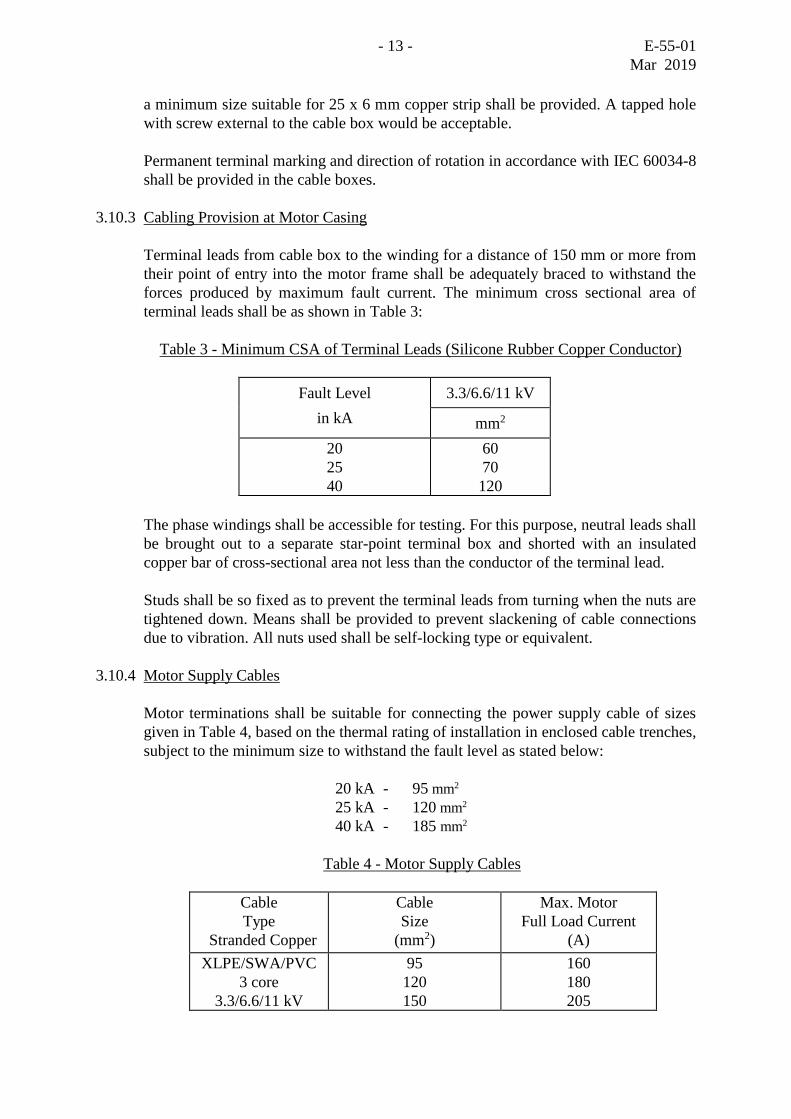
Terminal leads from cable box to the winding for a distance of 150 mm or more from
their point of entry into the motor frame shall be adequately braced to withstand the
forces produced by maximum fault current. The minimum cross sectional area of
terminal leads shall be as shown in Table 3:
Table 3 - Minimum CSA of Terminal Leads (Silicone Rubber Copper Conductor)
Fault Level 3.3/6.6/11 kV
in kA mm2
20
25
40
60
70
120
The phase windings shall be accessible for testing. For this purpose, neutral leads shall
be brought out to a separate star-point terminal box and shorted with an insulated
copper bar of cross-sectional area not less than the conductor of the terminal lead.
Studs shall be so fixed as to prevent the terminal leads from turning when the nuts are
tightened down. Means shall be provided to prevent slackening of cable connections
due to vibration. All nuts used shall be self-locking type or equivalent.
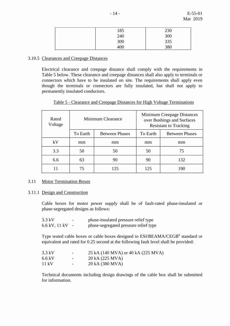
3.10.4 Motor Supply Cables
Motor terminations shall be suitable for connecting the power supply cable of sizes
given in Table 4, based on the thermal rating of installation in enclosed cable trenches,
subject to the minimum size to withstand the fault level as stated below:
20 kA - 95 mm2
25 kA - 120 mm2
40 kA - 185 mm2
Table 4 - Motor Supply Cables
Cable
Type
Stranded Copper
Cable
Size
(mm2)
Max. Motor
Full Load Current
(A)
XLPE/SWA/PVC
3 core
3.3/6.6/11 kV
95
120
150
160
180
205
- 14 - E-55-01
Mar 2019
185
240
300
400
230
300
335
380
3.10.5 Clearances and Creepage Distances
Electrical clearance and creepage distance shall comply with the requirements in
Table 5 below. These clearance and creepage distances shall also apply to terminals or
connectors which have to be insulated on site. The requirements shall apply even
though the terminals or connectors are fully insulated, but shall not apply to
permanently insulated conductors.
Table 5 - Clearance and Creepage Distances for High Voltage Terminations
Rated
Voltage
Minimum Clearance Minimum Creepage Distances
over Bushings and Surfaces
Resistant to Tracking
To Earth Between Phases To Earth Between Phases
kV mm mm mm mm
3.3 50 50 50 75
6.6 63 90 90 132
11 75 125 125 190
3.11 Motor Termination Boxes
3.11.1 Design and Construction
Cable boxes for motor power supply shall be of fault-rated phase-insulated or
phase-segregated designs as follows:
3.3 kV - phase-insulated pressure relief type
6.6 kV, 11 kV - phase-segregated pressure relief type
Type tested cable boxes or cable boxes designed to ESI/BEAMA/CEGB# standard or
equivalent and rated for 0.25 second at the following fault level shall be provided:
3.3 kV - 25 kA (140 MVA) or 40 kA (225 MVA)
6.6 kV - 20 kA (225 MVA)
11 kV - 20 kA (380 MVA)
Technical documents including design drawings of the cable box shall be submitted
for information.
- 15 - E-55-01
Mar 2019
Cable boxes shall have the following major design features:
(a) The cable box shall comprise an end box and an air insulated termination
chamber bolted together by means of high tensile steel bolts or studs and nuts
and of degree of protection to IEC 60529 IP 56.
(b) Termination boxes shall be fabricated from mild steel of rigid welded
construction. Cast iron boxes shall not be used.
(c) The termination chamber shall be bolted to the motor casing such that its sides
are vertical, with high tensile steel studs and nuts.
(d) The cable end box shall be of dry type suitable for cable termination in
Raychem heat shrinkable sleeving. It shall be fitted with a removable horizontal
gland plate suitable for bottom cable entry. No cable joint is permitted in the
end box.
(e) The termination chamber shall have an insulated assembly and be fitted with 3
stud terminals in insulating mouldings of epoxy resin, glass fibre, polyester or
approved similar material. Porcelain insulators and/or cable-coupler type
terminals shall not be used.
(f) Separate front access detachable cover plates shall be supplied for the end box
and termination chamber.
(g) Pressure relief device shall be fitted to prevent build-up of pressure in an
enclosed chamber.
(h) A plastic shroud or barrier having a minimum breakdown voltage of 20 kV
shall be fitted for each cable terminal.
3.11.2 Type Test Requirements
Unless cable boxes to ESI/BEAMA/CEGB standard are used, motor cable boxes shall
have been type tested as follows :
(a) Enclosure Test
Prototype cable boxes complete with cable end boxes should be tested to
demonstrate that an effective sealing/air tightness to IEC 60529 IP 56.
(b) Short-circuit Tests
Prototype cable boxes should be tested under the specified system voltage and
short-circuit conditions specified in Clause 3.11.1 by an independent Testing
Authority such as ASTA, UK or other organization of similar standing.
- 16 - E-55-01
Mar 2019
Tests should include the following:
(i) A three-phase through-fault current test.
(ii) A three-phase internal short-circuit test.
(iii) A single line-to-earth internal short-circuit test.
Test (i) should result in no mechanical or electrical damage.
Test (ii) should result in no external damage to the terminal box structure other
than rupturing of the pressure relief device. This test is not required for phase
segregated containment type cable boxes.
Test (iii) should result in no external damage to the terminal box structure other
than rupturing of the pressure relief device. For phase segregated containment
type terminal boxes the test should not result in spread or propagation of the
fault to or between the other two phases, which should be at rated potential for
the test.
Short circuit tests are not required for the stator star point termination box.
3.11.3 Termination Box Auxiliaries
Each containment chamber of the termination box shall be fitted with a screw-in type
desiccator with an indicator head. The desiccator shall be fitted such that the indicator
is readily visible and removable from the cable box. When the desiccator is removed,
access to live terminals shall be prevented by an internal metal barrier. This metal
barrier shall not reduce the clearances required inside the box. The desiccator shall be
fitted on a raised boss on a vertical box face to inhibit entry of contaminants when the
desiccator is removed. The size of the desiccator shall be designed such that with a
95% relative humidity, replacement of the drying agent will not be necessary for a
period of at least 3 months. The desiccant shall be silica gel crystals with humidity
sensitive dye.
3.12 Rotor Locking Device
A rotor locking device shall be fitted in the motor prior to shipment for protecting the
bearings against damage during transport. The device shall be of robust design and be
reusable for future maintenance.
3.13 Motor Information Plates
A motor wiring plate, a motor data plate and an oiling instruction plate made of
stainless steel shall be provided. The motor wiring plate shall give the connections and
the phase sequence for the required direction of rotation. The required direction of
rotation shall be marked on the motor casing.
The motor data plate shall be stamped with information required by IEC 60034-1. The
minimum coolant air quantity and the design letter for general characteristics to IEC
60034-12 shall also be marked.
- 17 - E-55-01
Mar 2019
The oiling instruction plate shall give the information of the name, type and model of
grease or lubrication oil for the motor bearings used.
The motor serial number shall be stamped with metal dies on the driving end shaft
face of the motor in addition to those being stamped on the stator.
4. PROTECTIVE EQUIPMENT & INSTRUMENTS
4.1 Winding Temperature Detectors
A set of embedded temperature detectors complying with IEC 60034-11, complete
with monitoring units shall be provided to afford Class II Protection for the motor.
At least six 3-wire RTD of the same characteristics suitably distributed around the
stator shall be installed and positioned at points at which the highest temperatures are
likely to occur. These positions are, e.g., two detectors between coil sides within the
slots, two detectors under the coils at the bottom of the slots and two detectors
between the coils and slot wedges and they shall be far apart from each other. Detector
leads shall be brought out to an auxiliary cable box such that any RTD may be isolated
for testing.
The RTD monitoring units for each motor shall have the following features:
(a) Alarm contacts to operate at 120C and adjustable for individual detecting
elements.
(b) Trip contacts to operate at 140C and adjustable for individual detecting
elements.
(c) A 4-20mA output signal corresponding to the measured temperature with
adjustable span and zero.
4.2 Bearing and Exhaust Air Temperature Detectors
A 3-wire RTD shall be installed for each bearing and for the motor exhaust air for
high temperature alarm and trip operation.
Unless recommended otherwise by the motor manufacturer, alarms detectors shall
operate at 10C lower than the trip detectors.
Insulated thermometer pockets shall be provided to enable easy insertion or removal
of temperature detector. The bearing/exhaust air temperature monitoring units for each
motor shall have the following features:
(a) Alarm contacts and trip contacts adjustable for individual detecting elements.
(b) A 4-20mA output signal corresponding to the measured temperature with
- 18 - E-55-01
Mar 2019
adjustable span and zero.
4.3 Bearing Coolant Failure Detector
Where water cooled bearings are used, a flow failure detector and associated strainer,
if required, shall be provided.
The flow detector shall be fitted with a pair of change-over contacts for alarm
initiation control.
4.4 Vibration Detector
At least two vibration detectors shall be installed for motors of 750 kW and above to
initiate alarm and tripping of pumpset when a preset vibration level is exceeded. The
detectors shall be located on different bearings and at perpendicular axes and of
acceleration sensitive type.
The vibration monitor unit shall have a continuously adjustable alarm/trip setting from
50-300% of the normal vibration amplitude. The equipment shall output a 4-20mA
signal corresponding to the measured vibration level in millimetres peak-to-peak with
adjustable zero and span. The overall error of the equipment shall not exceed 5% of
the full scale reading of the instrument range.
The detector shall be designed to prevent false alarm due to transient shocks by
incorporating a time-delay device of two seconds.
The unit shall be fitted with an alarm reset push button and alarm indicating lights.
4.5 Circuitry
Power supply to the monitoring units above-mentioned shall be 24V d.c.
The alarm and trip contacts shall be volt free and the contact rating shall be at least of
24V, 5A d.c. or 220V, 50Hz 5A inductive. The output contacts shall be normally open
and shall close on detection of an alarm condition such that tripping of motor shall not
occur due to failure of the auxiliary supply.
4.6 Pumpset Control Panel
An individual pumpset control panel will be provided by others for each pumpset.
The panel will be mounted adjacent to the motor. The following motor related
equipment to be mounted in the control panel shall be supplied loose with the motor:
(a) Motor winding temperature monitoring unit – 6 nos. (Clause 4.1)
(b) Motor bearing temperature monitoring unit – 2 nos. (Clause 4.2)
(c) Motor exhaust air temperature monitoring unit – 1 no. (Clause 4.2, for motor of
- 19 - E-55-01
Mar 2019
1,000 kW or above)
(d) Vibration monitor unit – 2 nos. (Clause 4.4, for motors of 750 kW or
above)
5. AUXILIARY EQUIPMENT
5.1 Power Factor Correction Capacitors
The motor will be connected and operated in parallel with a high voltage power factor
correction capacitor equipment complying with WSD Standard Specification
E-60-07” High-Voltage Power Factor Correction Capacitor”. The motor manufacturer
shall give all necessary technical information and advice for the correct sizing of the
matching capacitor.
5.2 Anti-condensation Heaters
Anti-condensation heaters shall be fitted and shall be suitable for operation on a 220V,
single phase, 50 hertz supply. Arrangements will be made in the switchgear to switch
off the heaters when the motor is running and vice versa. A separate IP 55 terminal
box shall be supplied for anti-condensation heater. The box shall be provided with
detachable gland plate. The box shall be provided with terminals for 2.5 mm2 2-core
PVCSWAPVC cable and a warning label “Separate Supply for Space Heater – Isolate
Before Opening this Lid”.
The heaters shall be replaceable strip type and complete with low watt density heating
elements such that the temperature measured at the motor casing at any point shall be
within 2 - 15 above the ambient temperature.
5.3 Marshalling Box for Protective Devices
Lead wires of protective devices such as vibration and temperature detectors and
equipment mounted on motor shall be protected by flexible stainless steel tubing/braid
sleeving, cleated and terminated to a IP 55 marshalling box mounted on the motor
casing.
The box shall be provided with detachable cable gland plates suitable for bottom entry
of steel wire armoured screened or coaxial instrumentation cables to BS EN 50288 or
equivalent standards.
5.4 Small Wiring
Wiring shall be in accordance with WSD Standard E-00-01 except where modified
herein.
Wiring liable to come in contact with oil shall have suitable oil resisting insulation.
The bared ends of stranded conductors shall be sweated together to prevent creepage
of oil along the wire.
- 20 - E-55-01
Mar 2019
High temperature insulation shall be provided on all wiring when this comes into
contact with the heated part of the motor.
Wiring in conduits shall not be used.
Wiring shall be run and fixed such that wiring can be checked against diagrams
without removing cleats.
An allowance shall be made on the length of each wire at the point of connection to
the terminal in order to permit the cutting off and re-making of the wire terminations
at least twice without causing a disturbance to the main run of wiring.
Wires shall be coloured black for a.c. connections, grey for d.c. connections and
yellow/green for earth connections.
Ferrules shall be fitted for each wire core such that they would not be detached
unintentionally when the wire is removed from the terminal.
6. SPARES AND TOOLS
6.1 Spares
The following spares shall be supplied loose for the motor:
(a) White metal pads for plain type thrust and guide bearings - one set for each
type.
(b) Ball and roller bearings - one complete unit for each size.
(c) Anti-condensation space heaters - one complete set for each motor.
Other spares required for one-year operation of the motors and associated electrical
equipment shall be separately priced in the tender.
6.2 Tools
Special maintenance tools for the motor shall be supplied. These shall include the
following:
(a) The necessary rotor locking device, slings and spreaders for transport of motor
and its components.
(b) One set of special tools as necessary for dismantling, overhaul and reassembly
of the motor e.g. rotor eye bolt.
(c) One no. of spare motor stool for each size of motors exceeding three in number.

- 21 - E-55-01
Mar 2019
7. INSPECTION AND TESTING
7.1 Inspection and Testing at the Manufacturer's Works
The motor shall be inspected and witness-tested by the Independent Inspection Body
(IIB) at the manufacturer's work prior to shipment in accordance with WSD Standard
Specification EM-00-01”Inspection, Testing and Reporting”.
Indicating meters (ammeter, voltmeter, wattmeter etc.) and measuring devices (C.T.,
V.T. etc.) used during tests shall be at least Class 0.5. The calibration results of these
instruments shall be provided to the IIB for inspection and included in the test report.
The inspection work shall in general cover the following : -
(a) General inspection checks including physical dimensions, workmanship, quality,
quantity, and standards.
(b) Check on model and nameplate data.
(c) Functional checks of correct operation and setting of equipment.
(d) Routine and basic tests as specified in Clause 7.3 below.
(e) Packing and protection checks.
Standard calibration tests on instruments/equipment by manufacturers shall not form
part of the normal inspection and hence shall not be witnessed by the IIB. In addition,
the quality assurance tests specified in Clause 7.2 need not be witnessed unless
specifically called for. However the test reports shall be submitted for verification
during inspection and the same shall be incorporated in the instruction manual.
7.2 Quality Control Tests
7.2.1 Motor Winding
During production of coils for the Contract, non-destructive electrical tests shall be
carried out to confirm insulation integrity. A random sample test measurement of loss
tangent to BS EN 50209 and the following high voltage impulse tests to at least two
sample coils in accordance with IEC 60034-15 shall be conducted:
Machine Rated Voltage
3.3 kV 6.6 kV 11 kV
Impulse voltage withstand test of interturn insulation
(a) Surge test voltage applied
across each coil
(5 surges, front time of 0.2s)
12 kV Peak
20 kV Peak
32 kV Peak
- 22 - E-55-01
Mar 2019
Power frequency voltage withstand test
(b) Earth insulation power
frequency withstand voltage
applied between coil terminals
and earth
(1 minute) *
7.6 kV
14.2kV
23 kV
* After the 1 minute test, the applied voltage shall be increased at the rate of 1 kV/s up
to 2 times the test voltage and then immediately reduced at a rate of at least 1 kV/s to
zero.
Where impregnation of winding is to be carried out with the coils in stator slots, the
above tests shall be conducted at reduced voltages on at least four sample coils
manufactured under the same batch of equipment supplied.
7.2.2 Protective Devices
Embedded temperature detectors (ETDs), bearing temperature detectors, coolant flow
detectors or any other protective devices where fitted shall be calibrated by suitable
means before being fitted into the motor.
7.3 Motor Tests
7.3.1 General
Tests conducted in the manufacturer's work shall be in accordance with IEC 60034
and BS EN 50209. No positive tolerance from specified limits shall be allowed for
noise level, temperature rise and starting (locked rotor) current.
The following basic tests shall be conducted on at least one motor of each size and
design supplied under this Contract. This motor shall be used for the subsequent pump
efficiency test:
(a) Temperature rise (IEC 60034-1)
(b) Efficiency at rated load and at pump efficiency test duty point (IEC 60034-2)
(c) Power factor at rated load and at pump efficiency test duty point
(d) Locked rotor torque
(e) Starting current
(f) Noise level (IEC 60034-9)
- 23 - E-55-01
Mar 2019
The following routine tests shall be conducted on each motor supplied:
(g) No load current, losses and power factor tests (IEC 60034-2)
(h) Vibration tests (IEC 60034-14)
(i) Dielectric measurement and tangent delta test (BS EN 50209)
(j) Withstand voltage test (IEC 60034-1)
(k) Stator winding resistance measurement (cold) and direction of rotation (IEC
60034-1)
(l) Hydraulic pressure test of water cooling circuit
(m) Insulation resistance test of auxiliary equipment
7.3.2 Withstand Voltage and Dielectric Tests
Withstand voltage tests shall be conducted in accordance with IEC 60034-1. The
manufacturer shall provide test reports recording the leakage current obtained.
The insulation resistance of the winding shall be measured and recorded at one minute
and 10 minute intervals with a megger (2,500V for 3.3 kV, 5 kV for 6.6 kV and 10 kV
for 11 kV motors) immediately before and after the withstand voltage test. The
polarization index shall be above 2.0.
The tangent delta of each phase winding shall be measured and the result shall not
exceed the figures stipulated in BS EN 50209 unless otherwise agreed by the WSD
prior to the test.
7.3.3 Vibration Level Test
The motor shall be tested for vibration to IEC 60034-14. The vibration levels of the
motor shall not exceed the “Grade A” limits given in the IEC standard.
7.3.4 Noise Level Test
Each motor shall be tested for noise level to IEC 60034-9. The calculated value at
reference condition shall not exceed the limits given in the IEC Standard.
Measurement and calculation details shall be submitted.
7.3.5 Efficiency Test
The efficiency figures for the motor shall be established by summation of losses in
accordance with IEC 60034-2.
- 24 - E-55-01
Mar 2019
7.3.6 Power Factor Test
The power factor test shall be conducted by direct loading at rated supply voltage and
frequency. Power factor at motor rated load based on results from indirect loading
tests, figures of losses, etc. will not be accepted without the special approval of the
WSD.
The guaranteed figures for the power factor at motor rated load and at the pump
efficiency test duty points shall be met.
7.3.7 Temperature Rise Test
The temperature of the motor winding shall be determined from the increase of
winding resistance.
Temperature rise test shall be conducted by direct loading at rated supply voltage and
frequency or by approved equivalent loading method with an auxiliary power of
different frequency superimposed to the main power source.
The test shall be conducted until the thermal equilibrium has been reached for over 2
hours. The temperature equilibrium shall be deemed to have been reached when the
rise of temperature of the stator winding does not exceed 2C over an hour period.
At least for the last 4 hours of the temperature rise test, the stator winding temperature
shall be measured by an instrument which has been calibrated to an accuracy
equivalent to 0.5C or better.
Where silencers, air ducting, filters etc. are required for the motors supplied,
temperature rise test shall be conducted with these devices fitted, except for the case
of long air ducts then an orifice plate shall be fitted during temperature rise test to
simulate the pressure loss.
The ambient temperature, motor outlet temperature and air flow quantity shall be
measured during temperature rise test to confirm that the actual rise in temperature
throughout the test is within the specified figure for the design air flow.
The surface temperature of the motor shall be measured when thermal equilibrium has
been reached. The temperature rise at any external parts which are liable to be touched
shall not exceed 25C.
7.3.8 Hydraulic Pressure Test
Bearing cooling coils where fitted shall be hydraulic pressure tested to 1.5 times
maximum working pressure.
7.3.9 Insulation Resistance Test
Insulation resistance tests shall be carried out on all auxiliary circuits including motor
heaters and ETDs. For motors with insulated bearing arrangement, the bearing
- 25 - E-55-01
Mar 2019
insulation and induced shaft voltages shall also be measured. The test method and
results shall be recorded in the report.
8. INFORMATION FOR EQUIPMENT APPROVAL
8.1 Catalogues and Performance Data
Catalogues, type test certificates and performance data of the motor, motor cable box,
motor winding coils, instruments and the various protective equipment shall be
submitted for assessment.
8.2 Pump and Motor Starting Characteristics
The pumpset starting characteristic shall be furnished for assessment and shall include
the following:
(a) Pump torque speed characteristic at the most arduous load condition with
closed delivery valve.
(b) Pump torque speed characteristic at the most arduous conditions with delivery
valve fully open.
(c) Motor torque characteristic at the lowest specified voltage across the motor
terminals i.e. 50% nominal voltage for auto-transformer starting, 80% for
direct-on-line starting.
The Y-axis shall be torque in N-m while the X-axis shall be the motor speed in rpm.
Characteristic curves plotted on per unit values are not acceptable.
8.3 Motor Thermal Characteristics
The short-time overload and stalling withstand characteristics of the motor (both hot
state and cold state) shall be submitted by plotting on a graph paper against the motor
thermal characteristics as given in Clause 3.3.
- End of this Specification -
#: ESI/BEAMA/CEGB stands for Electrical Supply Industry/British Electrotechnical and Allied Manufacturers Association/Central
Electricity Generating Board