Embed Size (px)
Citation preview

IM WT310E-17EN2nd Edition
Digital Power MeterWT310E/WT310EH/WT332E/WT333E
Communication Interface
iIM WT310E-17EN
Thank you for purchasing the WT310E, WT310EH, WT332E, or WT333E Digital Power Meter. This Communication Interface User’s Manual explains the following interface features and commands.• USBinterface• GP-IBinterface• RS-232interface• EthernetinterfaceTo ensure correct use, please read this manual thoroughly before beginning operation.After reading this manual, keep it in a safe place.
List of ManualsThe following manuals, including this one, are provided as manuals for this instrument. Please read all manuals.
Manual Title Manual No. DescriptionWT310E/WT310EH/WT332E/WT333E Digital Power Meter User’s Manual
IMWT310E-01EN The manual explains all features of this instrument, except for the communication interface features, and how to use them.
WT310E/WT310EH/WT332E/WT333E Digital Power Meter GettingStartedGuide
IMWT310E-02EN Provided as a printed manual. The manual explains the handling precautions and basic operations of this instrument and provides an overview of its features.
WT310E/WT310EH/WT332E/WT333E Digital Power Meter Communication Interface User’s Manual
IMWT310E-17EN This guide. This manual explains the communication interface features of this instrument and how to use them.
WT310E/WT310EH/WT332E/WT333E Digital Power Meter
IMWT310E-92Z1 Document for China
PDF files of all the manuals above are included in the accompanying CD.The“EN”and“Z1”inthemanualnumbersarethelanguagecodes.
Contact information of Yokogawa offices worldwide is provided on the following sheet.
Document No. DescriptionPIM113-01Z2 List of worldwide contacts
Notes• Thecontentsofthismanualaresubjecttochangewithoutpriornoticeasaresultofcontinuing
improvements to the instrument’s performance and functionality. The figures given in this manual may differ from those that actually appear on your screen.
• Everyefforthasbeenmadeinthepreparationofthismanualtoensuretheaccuracyofitscontents. However, should you have any questions or find any errors, please contact your nearestYOKOGAWAdealer.
• CopyingorreproducingalloranypartofthecontentsofthismanualwithoutthepermissionofYOKOGAWAisstrictlyprohibited.
• SafetyprecautionsareprovidedintheGettingStartedGuide,IMWT310E-02EN.Besuretoobserve the safety precautions.
• TheTCP/IPsoftwareofthisproductandthedocumentsconcerningithavebeendeveloped/createdbyYOKOGAWAbasedontheBSDNetworkingSoftware,Release1thathasbeenlicensedfromtheRegentsoftheUniversityofCalifornia.
Trademarks• Microsoft,InternetExplorer,MS-DOS,Windows,WindowsVista,Windows7,Windows8,and
Windows8.1areeitherregisteredtrademarksortrademarksofMicrosoftCorporationintheUnitedStatesand/orothercountries.
• AdobeandAcrobatareeitherregisteredtrademarksortrademarksofAdobeSystemsIncorporated.• ModbusisaregisteredtrademarkofAEGSchneider.• Inthismanual,the®andTMsymbolsdonotaccompanytheirrespectiveregisteredtrademark
or trademark names.• Othercompanyandproductnamesareregisteredtrademarksortrademarksoftheirrespectiveholders.
Revisions• 1stEdition: September2015• 2ndEdition: October2017
2ndEdition:October2017 (YMI)AllRightsReserved, Copyright ©2015YokogawaTest&MeasurementCorporation
ii IM WT310E-17EN
About the USB Interface and Ethernet Interface
• TousetheUSBcommunicationfeatures,yourPCmusthavethefollowing:• Library of this instrument (TMCTL)• USBdevicedriver for connecting this instrument to the PC
• TousetheEthernetcommunicationfeatures,yourPCmusthavethefollowing:• Libraryofthisinstrument(TMCTL)
You can download the library and driver from the following web page. http://tmi.yokogawa.com/
IfyouinstallWTViewerFreePlusinyourPC,theabovelibraryanddriverwillbeinstalledautomatically.
Sample Programs
Youcandownloadsampleprogramsforthisinstrumentfromthefollowingwebpage: http://tmi.yokogawa.com/
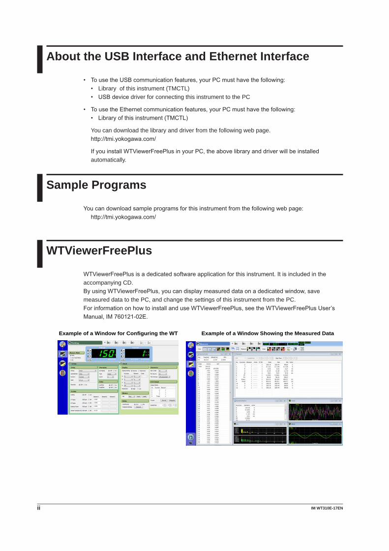
WTViewerFreePlus
WTViewerFreePlusisadedicatedsoftwareapplicationforthisinstrument.Itisincludedintheaccompanying CD.ByusingWTViewerFreePlus,youcandisplaymeasureddataonadedicatedwindow,savemeasured data to the PC, and change the settings of this instrument from the PC.ForinformationonhowtoinstallanduseWTViewerFreePlus,seetheWTViewerFreePlusUser’sManual,IM760121-02E.
Example of a Window Showing the Measured DataExample of a Window for Configuring the WT
iiiIM WT310E-17EN
Symbols and Notation Used in This Manual
NotesThe notes and cautions in this manual are categorized using the following symbols.
WARNING Calls attention to actions or conditions that could cause serious or fatal injury to the user, and precautions that can be taken to prevent such occurrences.
CAUTION Calls attention to actions or conditions that could cause light injury to the user or cause damage to the instrument or user’s data, and precautions that can be taken to prevent such occurrences.
French
AVERTISSEMENT Attire l’attention sur des gestes ou des conditions susceptibles de provoquer des blessures graves (voire mortelles), et sur les précautions de sécurité pouvant prévenir de tels accidents.
ATTENTION Attire l’attention sur des gestes ou des conditions susceptibles de provoquer des blessures légères ou d’endommager l’instrument ou les données de l’utilisateur, et sur les précautions de sécurité susceptibles de prévenir de tels accidents.
Note Calls attention to information that is important for proper operation of the instrument.
Unitsk Denotes1000.Example:100kHz(frequency)K Denotes1024.Example:720KB(filesize)
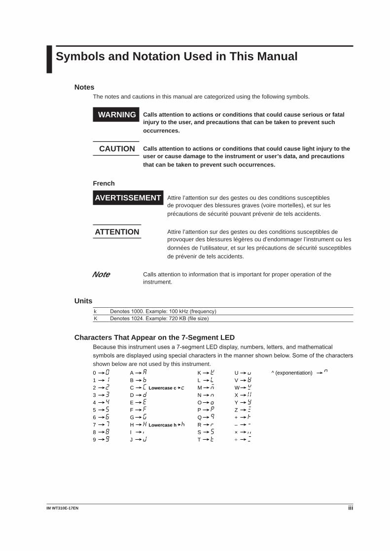
Characters That Appear on the 7-Segment LEDBecausethisinstrumentusesa7-segmentLEDdisplay,numbers,letters,andmathematicalsymbolsaredisplayedusingspecialcharactersinthemannershownbelow.Someofthecharactersshown below are not used by this instrument.
0123456789
ABCDEFGHIJ
KLMNOPQRST
Lowercase c
Lowercase h
UVWXYZ+–×÷
^ (exponentiation)
iv IM WT310E-17EN
Symbols and Conventions Used in Procedural ExplanationsIn chapters 1 to 4, the contents of the procedural explanations are indicated using the following symbols.
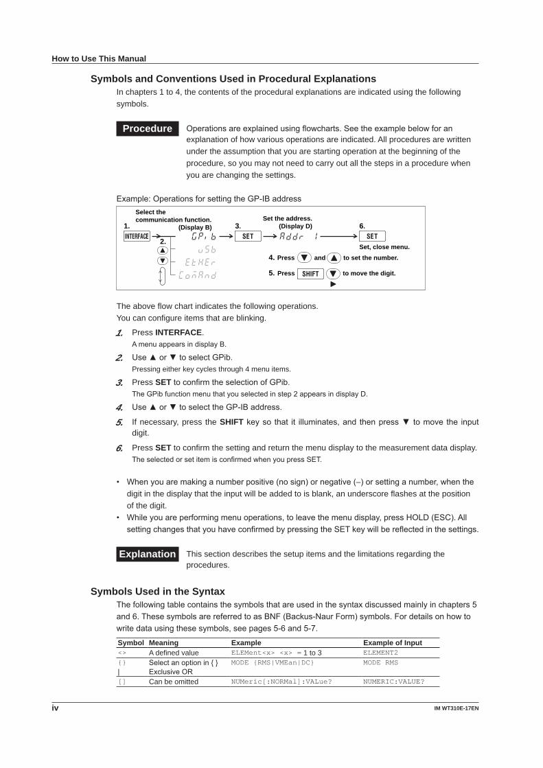
Procedure Operationsareexplainedusingflowcharts.Seetheexamplebelowforanexplanation of how various operations are indicated. All procedures are written under the assumption that you are starting operation at the beginning of the procedure, so you may not need to carry out all the steps in a procedure when you are changing the settings.
Example:OperationsforsettingtheGP-IBaddress
2.
Select the communication function.
(Display B)1. 3.Set the address.
(Display D) 6.
Press and to set the number.
Press to move the digit.
4.
5.
Set, close menu.
The above flow chart indicates the following operations.You can configure items that are blinking.
1. Press INTERFACE.AmenuappearsindisplayB.
2. Use▲or▼toselectGPib.Pressing either key cycles through 4 menu items.
3. Press SETtoconfirmtheselectionofGPib.TheGPibfunctionmenuthatyouselectedinstep2appearsindisplayD.
4. Use▲or▼toselecttheGP-IBaddress.
5. If necessary, press the SHIFTkeyso that it illuminates,and thenpress▼tomove the inputdigit.
6. Press SET to confirm the setting and return the menu display to the measurement data display.TheselectedorsetitemisconfirmedwhenyoupressSET.
• Whenyouaremakinganumberpositive(nosign)ornegative(–)orsettinganumber,whenthedigit in the display that the input will be added to is blank, an underscore flashes at the position of the digit.
• Whileyouareperformingmenuoperations,toleavethemenudisplay,pressHOLD(ESC).AllsettingchangesthatyouhaveconfirmedbypressingtheSETkeywillbereflectedinthesettings.
Explanation This section describes the setup items and the limitations regarding the procedures.
Symbols Used in the SyntaxThefollowingtablecontainsthesymbolsthatareusedinthesyntaxdiscussedmainlyinchapters5and6.ThesesymbolsarereferredtoasBNF(Backus-NaurForm)symbols.Fordetailsonhowtowritedatausingthesesymbols,seepages5-6and5-7.
Symbol Meaning Example Example of Input<> A defined value ELEMent<x> <x> = 1 to 3 ELEMENT2{}|
Selectanoptionin{}ExclusiveOR
MODE {RMS|VMEan|DC} MODE RMS
[] Can be omitted NUMeric[:NORMal]:VALue? NUMERIC:VALUE?
How to Use This Manual
vIM WT310E-17EN
1
2
3
4
5
6
7
8
9
App
Index
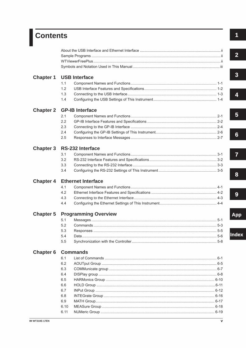
Contents
AbouttheUSBInterfaceandEthernetInterface .............................................................................. iiSamplePrograms ............................................................................................................................. iiWTViewerFreePlus ........................................................................................................................... iiSymbolsandNotationUsedinThisManual .................................................................................... iii
Chapter 1 USB Interface1.1 ComponentNamesandFunctions ................................................................................... 1-11.2 USBInterfaceFeaturesandSpecifications ...................................................................... 1-21.3 ConnectingtotheUSBInterface ...................................................................................... 1-31.4 ConfiguringtheUSBSettingsofThisInstrument ............................................................. 1-4
Chapter 2 GP-IB Interface2.1 ComponentNamesandFunctions ................................................................................... 2-12.2 GP-IBInterfaceFeaturesandSpecifications ................................................................... 2-22.3 ConnectingtotheGP-IBInterface ................................................................................... 2-42.4 ConfiguringtheGP-IBSettingsofThisInstrument........................................................... 2-62.5 ResponsestoInterfaceMessages ................................................................................... 2-7
Chapter 3 RS-232 Interface3.1 ComponentNamesandFunctions ................................................................................... 3-13.2 RS-232InterfaceFeaturesandSpecifications ................................................................. 3-23.3 ConnectingtotheRS-232Interface ................................................................................. 3-33.4 ConfiguringtheRS-232SettingsofThisInstrument ........................................................ 3-5
Chapter 4 Ethernet Interface4.1 ComponentNamesandFunctions ................................................................................... 4-14.2 EthernetInterfaceFeaturesandSpecifications ............................................................... 4-24.3 Connecting to the Ethernet Interface ................................................................................ 4-34.4 ConfiguringtheEthernetSettingsofThisInstrument ....................................................... 4-4
Chapter 5 Programming Overview5.1 Messages ......................................................................................................................... 5-15.2 Commands ....................................................................................................................... 5-35.3 Responses ....................................................................................................................... 5-55.4 Data .................................................................................................................................. 5-65.5 SynchronizationwiththeController .................................................................................. 5-8
Chapter 6 Commands6.1 ListofCommands ............................................................................................................ 6-16.2 AOUTputGroup ............................................................................................................... 6-56.3 COMMunicategroup ........................................................................................................ 6-76.4 DISPlaygroup .................................................................................................................. 6-86.5 HARMonicsGroup ......................................................................................................... 6-106.6 HOLDGroup ...................................................................................................................6-116.7 INPutGroup ................................................................................................................... 6-126.8 INTEGrateGroup ........................................................................................................... 6-166.9 MATHGroup................................................................................................................... 6-176.10 MEASureGroup ............................................................................................................. 6-186.11 NUMericGroup .............................................................................................................. 6-19
vi IM WT310E-17EN
Contents
6.12 RATEGroup ................................................................................................................... 6-296.13 RECallGroup ................................................................................................................. 6-306.14 STATusgroup ................................................................................................................. 6-316.15 STOReGroup................................................................................................................. 6-326.16 SYSTemGroup .............................................................................................................. 6-336.17 CommonCommandGroup ............................................................................................ 6-34
Chapter 7 Status Reports7.1 AboutStatusReports ....................................................................................................... 7-17.2 StatusByte ....................................................................................................................... 7-37.3 StandardEventRegister .................................................................................................. 7-47.4 ExtendedEventRegister .................................................................................................. 7-57.5 OutputandErrorQueues ................................................................................................. 7-6
Chapter 8 WT210/WT230 Compatible Commands8.1 WT210/WT230CompatibleCommandMode .................................................................. 8-1
Chapter 9 Modbus/TCP Communication9.1 OverviewofModbus/TCPCommunication....................................................................... 9-19.2 CommunicationwithClientDevices ................................................................................. 9-29.3 RegisterFunctionsandApplications ................................................................................ 9-3
AppendixAppendix 1 Error Messages ..................................................................................................App-1Appendix2 AbouttheIEEE488.2-1992Standard ................................................................App-5
Index
1-1IM WT310E-17EN
USB
Interface
1
2
3
4
5
6
7
8
9
App
Index
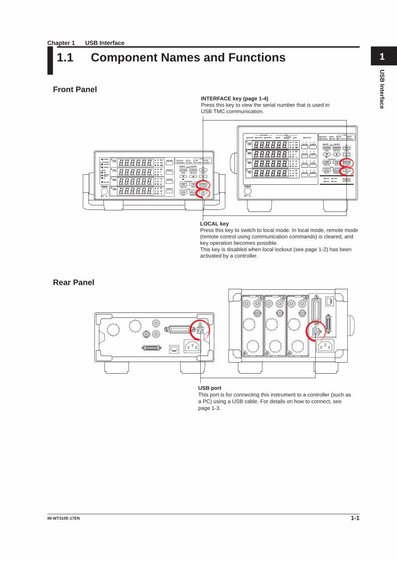
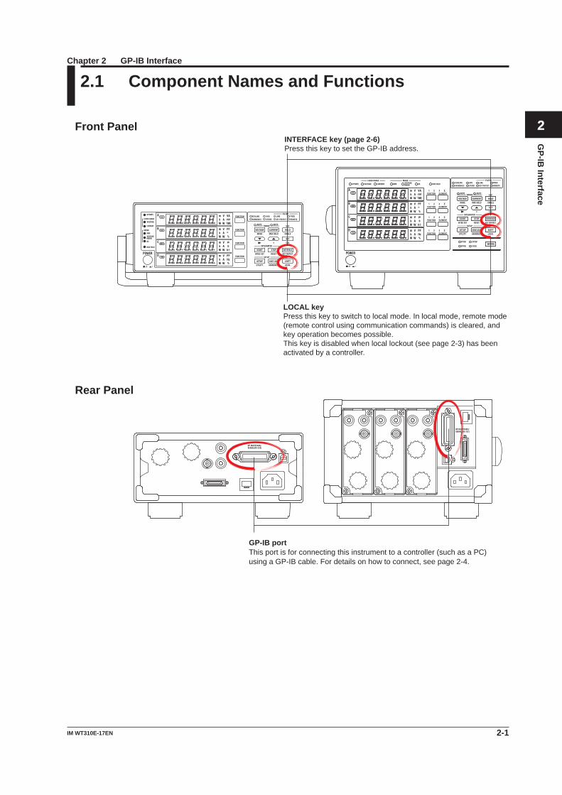
1.1 Component Names and Functions
Front Panel
LOCAL key Press this key to switch to local mode. In local mode, remote mode (remote control using communication commands) is cleared, and key operation becomes possible. This key is disabled when local lockout (see page 1-2) has been activated by a controller.
INTERFACE key (page 1-4) Press this key to view the serial number that is used in USB TMC communication.
Rear Panel
USB portThis port is for connecting this instrument to a controller (such as a PC) using a USB cable. For details on how to connect, see page 1-3.
Chapter 1 USB Interface
1-2 IM WT310E-17EN
1.2 USB Interface Features and Specifications
USB Interface FeaturesReception Feature• Youcanusethereceptionfeaturetospecifythesamesettingsthatyouspecifybyusingthefront
panel keys.• Outputrequestsformeasuredandcomputeddata,panelsetupparameters,anderrorcodescan
be received.
Transmission Feature• Thisinstrumentcantransmitmeasuredandcomputeddata.• Thisinstrumentcantransmitpanelsetupparametersandthestatusbyte.• Thisinstrumentcantransmiterrorcodeswhenerrorsoccur.
USB Interface SpecificationsItem SpecificationsNumberofports 1Connector TypeBconnector(receptacle)Electrical and mechanical ComplieswithUSBRev.2.0Supportedtransfermodes HS(HighSpeed;480Mbps)andFS(FullSpeed;12Mbps)Supportedprotocols USBTMC-USB488(USBTestandMeasurementClassVer.1.0)PC system requirements PCrunningWindows8(32bit/64bit),Windows7(32bit/64bit),orWindows
Vista(32bit)EnglishandJapaneseandwithaUSBport
Switching between Remote and Local ModesWhen Switching from Local to Remote ModeThis instrument switches to remote mode when it is in local mode and it receives a :COMMunicate:REMoteONcommandfromthePC.• TheREMOTEindicatorilluminates.• AllkeysexcepttheSHIFT (LOCAL) key are disabled.• Settingsenteredinlocalmodeareretainedevenwhenthisinstrumentswitchestoremotemode.
When Switching from Remote to Local ModeWhenthisinstrumentisinremotemodeandyoupressSHIFT(LOCAL),thisinstrumentswitches to local mode. However, this does not work if this instrument has received a :COMMunicate:LOCKout ON command from the PC. This instrument switches to local mode when it receives a :COMMunicate:REMote OFF command from the PC, regardless of the local lockout state.• TheREMOTEindicatorturnsoff.• Keyoperationsareenabled.• Settingsenteredinremotemodeareretainedevenwhenthisinstrumentswitchestolocalmode.
NoteYoucannotusetheUSBinterfacesimultaneouslywithotherinterfaces(GP-IB,RS-232,andEthernetinterfaces).
1-3IM WT310E-17EN
USB
Interface
1
2
3
4
5
6
7
8
9
App
Index
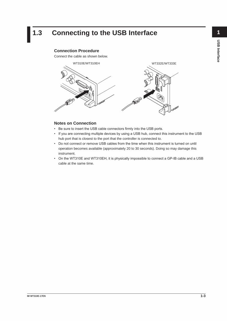
1.3 Connecting to the USB Interface
Connection ProcedureConnect the cable as shown below.
WT310E/WT310EH WT332E/WT333E
Notes on Connection• BesuretoinserttheUSBcableconnectorsfirmlyintotheUSBports.• IfyouareconnectingmultipledevicesbyusingaUSBhub,connectthisinstrumenttotheUSB
hub port that is closest to the port that the controller is connected to.• DonotconnectorremoveUSBcablesfromthetimewhenthisinstrumentisturnedonuntil
operation becomes available (approximately 20 to 30 seconds). Doing so may damage this instrument.
• OntheWT310EandWT310EH,itisphysicallyimpossibletoconnectaGP-IBcableandaUSBcable at the same time.
1-4 IM WT310E-17EN
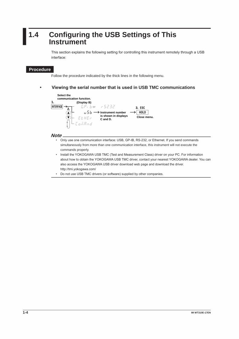
1.4 Configuring the USB Settings of This InstrumentThissectionexplainsthefollowingsettingforcontrollingthisinstrumentremotelythroughaUSBinterface:
ProcedureFollow the procedure indicated by the thick lines in the following menu.
• ViewingtheserialnumberthatisusedinUSB TMC communications
2.
Select the communication function.
1.
Instrument number is shown in displays C and D.
Close menu.
or 3.(Display B)
Note• Onlyuseonecommunicationinterface:USB,GP-IB,RS-232,orEthernet.Ifyousendcommands
simultaneously from more than one communication interface, this instrument will not execute the commands properly.
• InstalltheYOKOGAWAUSBTMC(TestandMeasurementClass)driveronyourPC.ForinformationabouthowtoobtaintheYOKOGAWAUSBTMCdriver,contactyournearestYOKOGAWAdealer.YoucanalsoaccesstheYOKOGAWAUSBdriverdownloadwebpageanddownloadthedriver.
http://tmi.yokogawa.com/• DonotuseUSBTMCdrivers(orsoftware)suppliedbyothercompanies.
2-1IM WT310E-17EN
GP-IB
Interface
Chapter 2 GP-IB Interface
1
2
3
4
5
6
7
8
9
App
Index
2.1 Component Names and Functions
Front Panel
LOCAL key Press this key to switch to local mode. In local mode, remote mode (remote control using communication commands) is cleared, and key operation becomes possible. This key is disabled when local lockout (see page 2-3) has been activated by a controller.
INTERFACE key (page 2-6) Press this key to set the GP-IB address.
Rear Panel
GP-IB portThis port is for connecting this instrument to a controller (such as a PC) using a GP-IB cable. For details on how to connect, see page 2-4.
2-2 IM WT310E-17EN
2.2 GP-IB Interface Features and Specifications
GP-IB Interface FeaturesReception Feature• Youcanusethereceptionfeaturetospecifythesamesettingsthatyouspecifybyusingthefront
panel keys.• Outputrequestsformeasuredandcomputeddata,panelsetupparameters,anderrorcodescan
be received.
Transmission Feature• Thisinstrumentcantransmitmeasuredandcomputeddata.• Thisinstrumentcantransmitpanelsetupparametersandthestatusbyte.• Thisinstrumentcantransmiterrorcodeswhenerrorsoccur.
NoteTalk-only,listen-only,andcontrollercapabilitiesarenotavailable.
GP-IB Interface SpecificationsItem SpecificationsSupporteddevices NationalInstrumentsCorporation
• PCI-GPIBorPCI-GPIB+•PCIe-GPIBorPCIe-GPIB+•PCMCIA-GPIBorPCMCIA-GPIB+(notsupportedonWindowsVistaorWindows7.)
•GPIB-USB-HSDriverNI-488.2MVersion2.8.1andlater
Electrical and mechanical ConformstoIEEESt’d488-1978Functional specifications Seethetablebelow.Protocol ConformstoIEEESt’d488.2-1992Code ISO(ASCII)codesMode Addressable modeAddress setting Press INTERFACE, and then select the GPIBmenu.Settheaddresstoa
value between 0 and 30.Clear remote mode Press SHIFT (LOCAL) to clear remote mode.
This is not possible when local lockout has been activated by the controller.
Functional SpecificationsFunction Subset Name DescriptionSourcehandshaking SH1 Full source handshaking capabilityAcceptor handshaking AH1 Full acceptor handshaking capabilityTalker T6 Basictalkercapability,serialpolling,anduntalkonMLA(My
ListenAddress).Notalk-onlycapability.Listener L4 BasiclistenercapabilityandunlistenonMTA(MyTalkAddress).
Nolisten-onlycapabilityServicerequest SR1 Full service request capabilityRemotelocal RL1 Full remote/local capabilityParallel polling PP0 NoparallelpollingcapabilityDevice clear DC1 Full device clear capabilityDevice trigger DT1 Device trigger capabilityController C0 NocontrollercapabilityElectric characteristics E1 Open collector
2-3IM WT310E-17EN
GP-IB
Interface
2.2 GP-IB Interface Features and Specifications
1
2
3
4
5
6
7
8
9
App
Index
Switching between Remote and Local ModesWhen Switching from Local to Remote ModeThisinstrumentswitchestoremotemodewhenitisinlocalmodeanditreceivesaREN(RemoteEnable) message from the PC.• TheREMOTEindicatorilluminates.• AllkeysexcepttheSHIFT (LOCAL) key are disabled.• Settingsenteredinlocalmodeareretainedevenwhenthisinstrumentswitchestoremotemode.
When Switching from Remote to Local ModeWhen this instrument is in remote mode and you press SHIFT (LOCAL), this instrument switches tolocalmode.Thiskeyisdisabledwhenlocallockout(seepage2-7)hasbeenactivatedbyacontroller.• TheREMOTEindicatorturnsoff.• Keyoperationsareenabled.• Settingsenteredinremotemodeareretainedevenwhenthisinstrumentswitchestolocalmode.
NoteYoucannotusetheGP-IBinterfacesimultaneouslywithotherinterfaces(USBandEthernetinterfaces).
2-4 IM WT310E-17EN
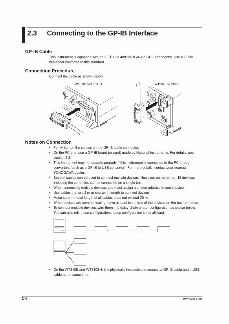
2.3 Connecting to the GP-IB Interface
GP-IB CableThisinstrumentisequippedwithanIEEESt’d488-197824-pinGP-IBconnector.UseaGP-IBcable that conforms to this standard.
Connection ProcedureConnect the cable as shown below.
WT310E/WT310EH WT332E/WT333E
Notes on Connection• FirmlytightenthescrewsontheGP-IBcableconnector.• OnthePCend,useaGP-IBboard(orcard)madebyNationalInstruments.Fordetails,see
section 2.2.• ThisinstrumentmaynotoperateproperlyifthisinstrumentisconnectedtothePCthrough
converters(suchasaGP-IBtoUSBconverter).Formoredetails,contactyournearestYOKOGAWAdealer.
• Severalcablescanbeusedtoconnectmultipledevices.However,nomorethan15devices,including the controller, can be connected on a single bus.
• Whenconnectingmultipledevices,youmustassignauniqueaddresstoeachdevice.• Usecablesthatare2morshorterinlengthtoconnectdevices.• Makesurethetotallengthofallcablesdoesnotexceed20m.• Whendevicesarecommunicating,haveatleasttwo-thirdsofthedevicesonthebusturnedon.• Toconnectmultipledevices,wiretheminadaisy-chainorstarconfigurationasshownbelow.
You can also mix these configurations. Loop configuration is not allowed.
• OntheWT310EandWT310EH,itisphysicallyimpossibletoconnectaGP-IBcableandaUSBcable at the same time.

2-5IM WT310E-17EN
GP-IB
Interface
2.3 Connecting to the GP-IB Interface
1
2
3
4
5
6
7
8
9
App
Index
CAUTIONBesuretoturnoffthePCandthisinstrumentbeforeyouconnectorremovecommunicationcables. Otherwise, erroneous operation may result, or the internal circuitry may break.
French
ATTENTIONVeilleràmettrelePCetl’instrumenthorstensionavantdebrancheroudedébrancherlescâblesdecommunication,pouréviterdeprovoquerdesdysfonctionnementsoudescourts-circuits internes.
2-6 IM WT310E-17EN
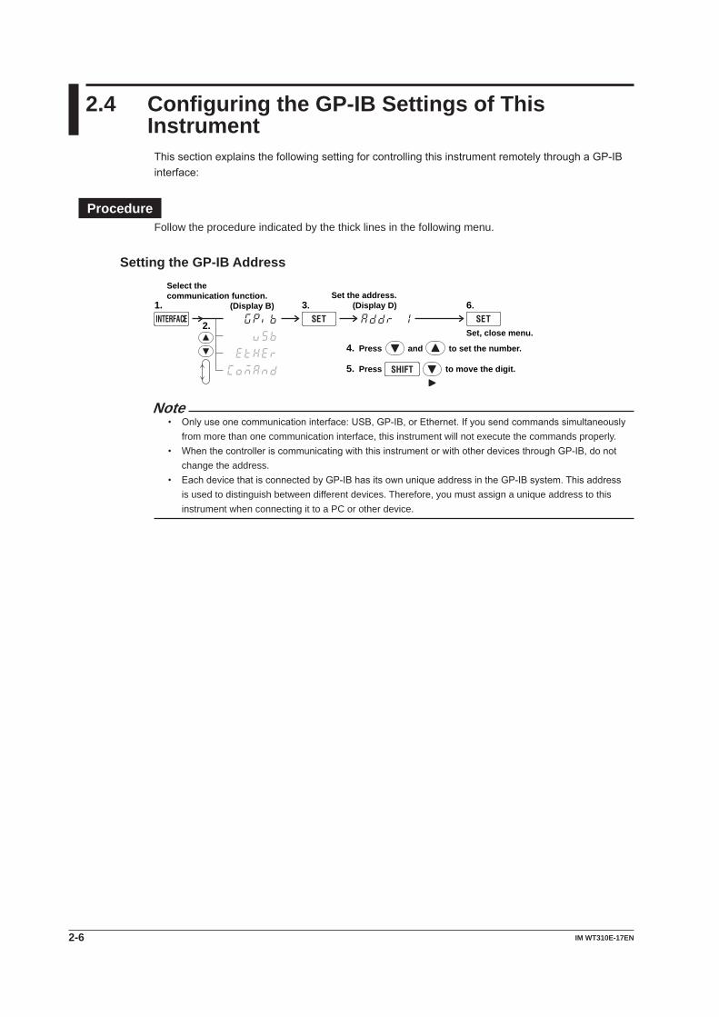
2.4 Configuring the GP-IB Settings of This InstrumentThissectionexplainsthefollowingsettingforcontrollingthisinstrumentremotelythroughaGP-IBinterface:
ProcedureFollow the procedure indicated by the thick lines in the following menu.
Setting the GP-IB Address
2.
Select the communication function.
1. 3.Set the address.
(Display D) 6.
Press and to set the number.
Press to move the digit.
4.
5.
Set, close menu.
(Display B)
Note• Onlyuseonecommunicationinterface:USB,GP-IB,orEthernet.Ifyousendcommandssimultaneously
from more than one communication interface, this instrument will not execute the commands properly.• WhenthecontrolleriscommunicatingwiththisinstrumentorwithotherdevicesthroughGP-IB,donot
change the address.• EachdevicethatisconnectedbyGP-IBhasitsownuniqueaddressintheGP-IBsystem.Thisaddress
is used to distinguish between different devices. Therefore, you must assign a unique address to this instrument when connecting it to a PC or other device.
2-7IM WT310E-17EN
GP-IB
Interface
1
2
3
4
5
6
7
8
9
App
Index
2.5 Responses to Interface Messages
Responses to Interface MessagesResponses to Uni-Line Messages• IFC (Interface Clear) Clearsthetalkerandlistenerfunctions.Stopsdatatransmissionifitisinprogress.
• REN (Remote Enable) Switchesbetweentheremoteandlocalmodes.
IDY (Identify) is not supported.
Responses to Multi-Line Messages (Address commands)• GTL (Go To Local) Switchestheinstrumenttolocalmode.
• SDC (Selected Device Clear)• Clearstheprogrammessage(command)beingreceivedandtheoutputqueue(seepage7-6
for details).• Discards*OPCand*OPC?commandsthatarebeingexecuted.• Immediatelyaborts*WAIandCOMMunicate:WAITcommands.
• GET (Group Execute Trigger) Thesameoperationasthe*TRGcommand.
PPC (Parallel Poll Configure) and TCT (Take Control) are not supported.
Responses to Multi-Line Messages (Universal commands)• LLO (Local Lockout) Prohibits switching to local mode by disabling the LOCAL key on the front panel.
• DCL (Device Clear) ThesameoperationastheSDCmessage.
• SPE (Serial Poll Enable) Setsthetalkerfunctiononalldevicesonthebustoserialpollingmode.Thecontrollerwillpoll
each device one by one.
• SPD (Serial Poll Disable) Clears the serial polling mode of the talker function on all devices on the bus.
PPU (Parallel Poll Unconfigure) is not supported.
What Are Interface Messages?Interface messages are also referred to as interface commands or bus commands. They are commandsthatareissuedbythecontroller.Theyareclassifiedasfollows:
Uni-line MessagesAsinglecontrollineisusedtotransmituni-linemessages.Thefollowingthreetypesareavailable.• IFC(InterfaceClear)• REN(RemoteEnable)• IDY(Identify)
2-8 IM WT310E-17EN
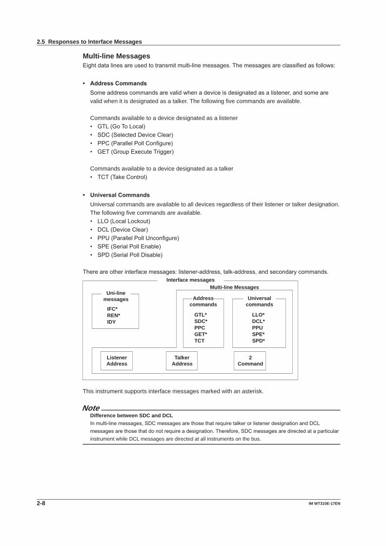
2.5 Responses to Interface Messages
Multi-line MessagesEightdatalinesareusedtotransmitmulti-linemessages.Themessagesareclassifiedasfollows:
• AddressCommands Someaddresscommandsarevalidwhenadeviceisdesignatedasalistener,andsomeare
valid when it is designated as a talker. The following five commands are available.
Commands available to a device designated as a listener• GTL(GoToLocal)• SDC(SelectedDeviceClear)• PPC(ParallelPollConfigure)• GET(GroupExecuteTrigger)
Commands available to a device designated as a talker• TCT(TakeControl)
• UniversalCommands Universal commands are available to all devices regardless of their listener or talker designation.
The following five commands are available.• LLO(LocalLockout)• DCL(DeviceClear)• PPU(ParallelPollUnconfigure)• SPE(SerialPollEnable)• SPD(SerialPollDisable)
Thereareotherinterfacemessages:listener-address,talk-address,andsecondarycommands.
Interface messages
Uni-line messages Address
commands Universal
commands IFC*REN*IDY
GTL*SDC*PPCGET*TCT
LLO*DCL*PPUSPE*SPD*
Listener Address
Talker Address
2 Command
Multi-line Messages
This instrument supports interface messages marked with an asterisk.
NoteDifference between SDC and DCLInmulti-linemessages,SDCmessagesarethosethatrequiretalkerorlistenerdesignationandDCLmessagesarethosethatdonotrequireadesignation.Therefore,SDCmessagesaredirectedataparticularinstrument while DCL messages are directed at all instruments on the bus.
3-1IM WT310E-17EN
RS-232 Interface
1
2
3
4
5
6
7
8
9
App
Index
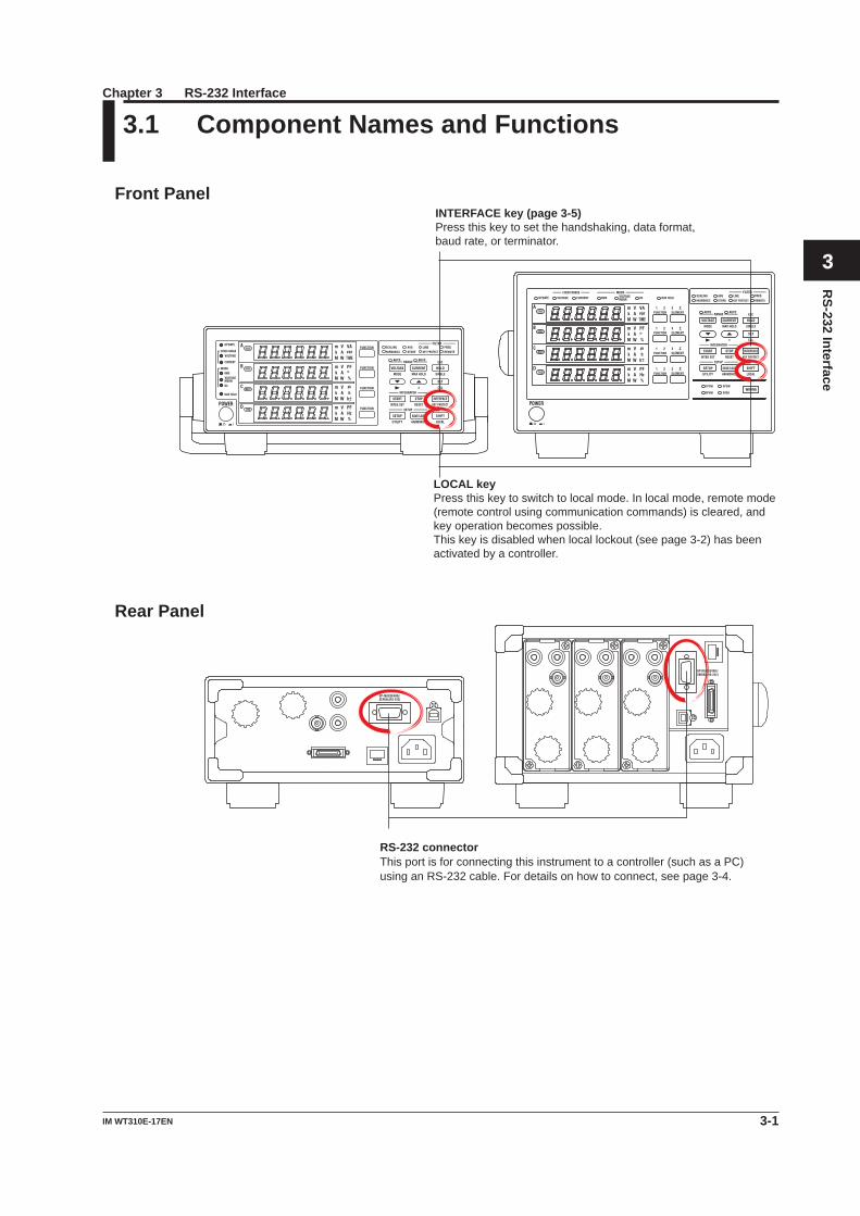
3.1 Component Names and Functions
Front Panel
LOCAL key Press this key to switch to local mode. In local mode, remote mode (remote control using communication commands) is cleared, and key operation becomes possible. This key is disabled when local lockout (see page 3-2) has been activated by a controller.
INTERFACE key (page 3-5) Press this key to set the handshaking, data format, baud rate, or terminator.
Rear Panel
RS-232 connectorThis port is for connecting this instrument to a controller (such as a PC) using an RS-232 cable. For details on how to connect, see page 3-4.
Chapter 3 RS-232 Interface
3-2 IM WT310E-17EN
3.2 RS-232 Interface Features and Specifications
RS-232 Interface FeaturesReception Feature• Youcanusethereceptionfeaturetospecifythesamesettingsthatyouspecifybyusingthefront
panel keys.• Outputrequestsformeasuredandcomputeddata,panelsetupparameters,anderrorcodescan
be received.
Transmission Feature• Thisinstrumentcantransmitmeasuredandcomputeddata.• Thisinstrumentcantransmitpanelsetupparametersandthestatusbyte.• Thisinstrumentcantransmiterrorcodeswhenerrorsoccur.
RS-232 Interface SpecificationsItem SpecificationsElectrical specifications ComplieswithEIA-574(EIA-232(RS-232)standardfor9-pin)Connection Point to pointTransmission mode Full duplexSynchronization Start-stopsynchronizationBaudrate 1200,2400,4800,9600,19200,38400,57600Startbit 1 bit (fixed)Data length 7or8bitsParity Even, odd, no parityStopbits 1 or 2 bitsConnector DELC-J9PAF-13L6(JAEorequivalent)Hardware handshaking SelectwhethertousetheCAandCBsignalsascontrollerlinesorassumethat
they are always true.Softwarehandshaking TransmissionandreceptioncanbecontrolledwithX-ONandX-OFFsignals.
X-ON(ASCII11H)X-OFF(ASCII13H)
Receivebuffersize 256bytes.
Switching between Remote and Local ModesWhen Switching from Local to Remote ModeThis instrument switches to remote mode when it is in local mode and it receives a :COMMunicate:REMote ON command from the PC.• TheREMOTEindicatorilluminates.• AllkeysexcepttheSHIFT (LOCAL) key are disabled.• Settingsenteredinlocalmodeareretainedevenwhenthisinstrumentswitchestoremotemode.
When Switching from Remote to Local ModeWhenthisinstrumentisinremotemodeandyoupressSHIFT(LOCAL),thisinstrumentswitchestolocalmode.However,thisdoesnotworkifthisinstrumenthasreceiveda:COMMunicate:LOCKoutONcommandfromthePC.Thisinstrumentswitchestolocalmodewhenitreceivesa:COMMunicate:REMoteOFFcommandfromthePC,regardlessofthelocallockoutstate.• TheREMOTEindicatorturnsoff.• Keyoperationsareenabled.• Settingsenteredinremotemodeareretainedevenwhenthisinstrumentswitchestolocalmode.
NoteYoucannotusetheRS-232interfacesimultaneouslywithothercommunicationinterfaces(USBandEthernetinterfaces).
3-3IM WT310E-17EN
RS-232 Interface
1
2
3
4
5
6
7
8
9
App
Index
3.3 Connecting to the RS-232 Interface
To connect this instrument to a PC, use an interface cable that is compatible with this instrument specifications.Besuretoalignthehandshaking,datatransferrate,dataformat,andsoonwiththePC. For the settings, see section 3.4.
Connector and Signal Names
DELC-J9PAF-13L6 or equivalent
2
1
3 4 5
6 7 8 9
2 1 3 4 5
6 7 8 9
WT332E/WT333EWT310E/WT310EH
Pin No. Signal Name Input or Output Function2 RD(ReceivedData) Input Data received from the PC3 SD(SendData) Output Data sent to the PC5 SG(SignalGround) ---- Signalground7 RS(RequesttoSend) Output Handshaking signal for receiving data from the PC8 CS(CleartoSend) Input Handshaking signal for sending data to the PC
*Pins1,4,6,and9arenotused.
9-pin to 25-pin Adapter and Signal Names
58723(2) (3) (4) (5) (7)
Numbersinparenthesesarepinnumbersforthe25-pinconnector.
Signal DirectionThefollowingfigureshowsthedirectionsofthesignalsofthisinstrumentRS-232interface.
PC This instrument
RS [Request to send]
SD [Send data]
RD [Receive data] 2
3
8
7
CS [Clear to send]
3-4 IM WT310E-17EN
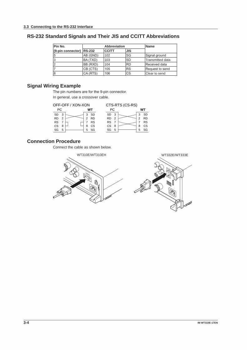
RS-232 Standard Signals and Their JIS and CCITT Abbreviations
Pin No. Abbreviation Name(9-pin connector) RS-232 CCITT JIS5 AB(GND) 102 SG Signalground3 BA(TXD) 103 SD Transmitted data2 BB(RXD) 104 RD Receiveddata7 CB(CTS) 105 RS Requesttosend8 CA(RTS) 106 CS Clear to send
Signal Wiring ExampleThepinnumbersareforthe9-pinconnector.In general, use a crossover cable.
SDRDRSCSSG
SDRDRS
SG
CTS-RTS (CS-RS)PC WT
CS
2 3
8 7
5
2 3
8 7
5
SDRDRSCSSG
SDRDRS
SG
OFF-OFF / XON-XONPC WT
CS
2 3
8 7
5
2 3
8 7
5
Connection ProcedureConnect the cable as shown below.
WT310E/WT310EH WT332E/WT333E
3.3 Connecting to the RS-232 Interface

3-5IM WT310E-17EN
RS-232 Interface
1
2
3
4
5
6
7
8
9
App
Index
3.4 Configuring the RS-232 Settings of This InstrumentThissectionexplainsthefollowingsettingforcontrollingthisinstrumentremotelythroughaRS-232interface:
ProcedureFollow the procedure indicated by the thick lines in the following menu.
2.
Select the communication function.
1. 3.Set the handshaking.
(Display A)
4.
5.
6.
Set the data format.(Display B) 7.
9.
8.
Set the baud rate.(Display C)
10.
Set the terminator.(Display D) 11.
Set, close menu.
(Display B)
NoteOnlyuseonecommunicationinterface:USB,RS-232,orEthernet.Ifyousendcommandssimultaneouslyfrom more than one communication interface, this instrument will not execute the commands properly.
3-6 IM WT310E-17EN
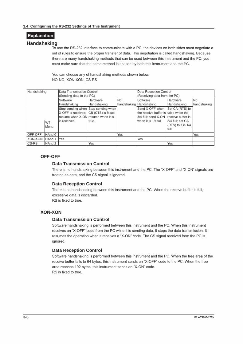
ExplanationHandshaking
TousetheRS-232interfacetocommunicatewithaPC,thedevicesonbothsidesmustnegotiateasetofrulestoensurethepropertransferofdata.Thisnegotiationiscalledhandshaking.Becausethere are many handshaking methods that can be used between this instrument and the PC, you must make sure that the same method is chosen by both this instrument and the PC.
You can choose any of handshaking methods shown below.NO-NO,XON-XON,CS-RS
Handshaking Data Transmission Control(SendingdatatothePC)
DataReceptionControl(ReceivingdatafromthePC)
SoftwareHandshaking
HardwareHandshaking
Nohandshaking
SoftwareHandshaking
HardwareHandshaking
Nohandshaking
StopsendingwhenX-OFFisreceived;resumewhenX-ONis received.
StopsendingwhenCB(CTS)isfalse;resume when it is true.
SendX-OFFwhenthe receive buffer is 3/4full;sendX-ONwhen it is 1/4 full.
SetCA(RTS)tofalse when the receive buffer is 3/4full;setCA(RTS)toitis1/4full.
WTMenu
OFF-OFF HAnd 0 Yes YesXON-XON HAnd 1 Yes YesCS-RS HAnd 2 Yes Yes
OFF-OFFData Transmission ControlThereisnohandshakingbetweenthisinstrumentandthePC.The“X-OFF”and“X-ON”signalsaretreatedasdata,andtheCSsignalisignored.
Data Reception ControlThere is no handshaking between this instrument and the PC. When the receive buffer is full, excessive data is discarded.RSisfixedtotrue.
XON-XONData Transmission ControlSoftwarehandshakingisperformedbetweenthisinstrumentandthePC.Whenthisinstrumentreceivesan“X-OFF”codefromthePCwhileitissendingdata,itstopsthedatatransmission.Itresumestheoperationwhenitreceivesa“X-ON”code.TheCSsignalreceivedfromthePCisignored.
Data Reception ControlSoftwarehandshakingisperformedbetweenthisinstrumentandthePC.Whenthefreeareaofthereceivebufferfallsto64bytes,thisinstrumentsendsan“X-OFF”codetothePC.Whenthefreeareareaches192bytes,thisinstrumentsendsan“X-ON”code.RSisfixedtotrue.
3.4 Configuring the RS-232 Settings of This Instrument
3-7IM WT310E-17EN
RS-232 Interface
1
2
3
4
5
6
7
8
9
App
Index
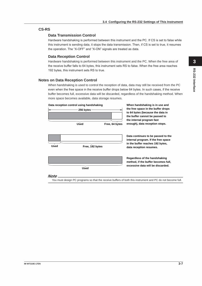
CS-RSData Transmission ControlHardwarehandshakingisperformedbetweenthisinstrumentandthePC.IfCSissettofalsewhilethisinstrumentissendingdata,itstopsthedatatransmission.Then,ifCSissettotrue,itresumestheoperation.The“X-OFF”and“X-ON”signalsaretreatedasdata.
Data Reception ControlHardware handshaking is performed between this instrument and the PC. When the free area of thereceivebufferfallsto64bytes,thisinstrumentsetsRStofalse.Whenthefreeareareaches192bytes,thisinstrumentsetsRStotrue.
Notes on Data Reception ControlWhen handshaking is used to control the reception of data, data may still be received from the PC evenwhenthefreespaceinthereceivebufferdropsbelow64bytes.Insuchcases,ifthereceivebuffer becomes full, excessive data will be discarded, regardless of the handshaking method. When more space becomes available, data storage resumes.
256 bytes
Used Free, 64 bytes
When handshaking is in use and the free space in the buffer drops to 64 bytes (because the data in the buffer cannot be passed to the internal program fast enough), data reception stops.
Used Free, 192 bytes
Data continues to be passed to the internal program. If the free space in the buffer reaches 192 bytes, data reception resumes.
Used
Regardless of the handshaking method, if the buffer becomes full, excessive data will be discarded.
Data reception control using handshaking
NoteYou must design PC programs so that the receive buffers of both this instrument and PC do not become full.
3.4 Configuring the RS-232 Settings of This Instrument
3-8 IM WT310E-17EN
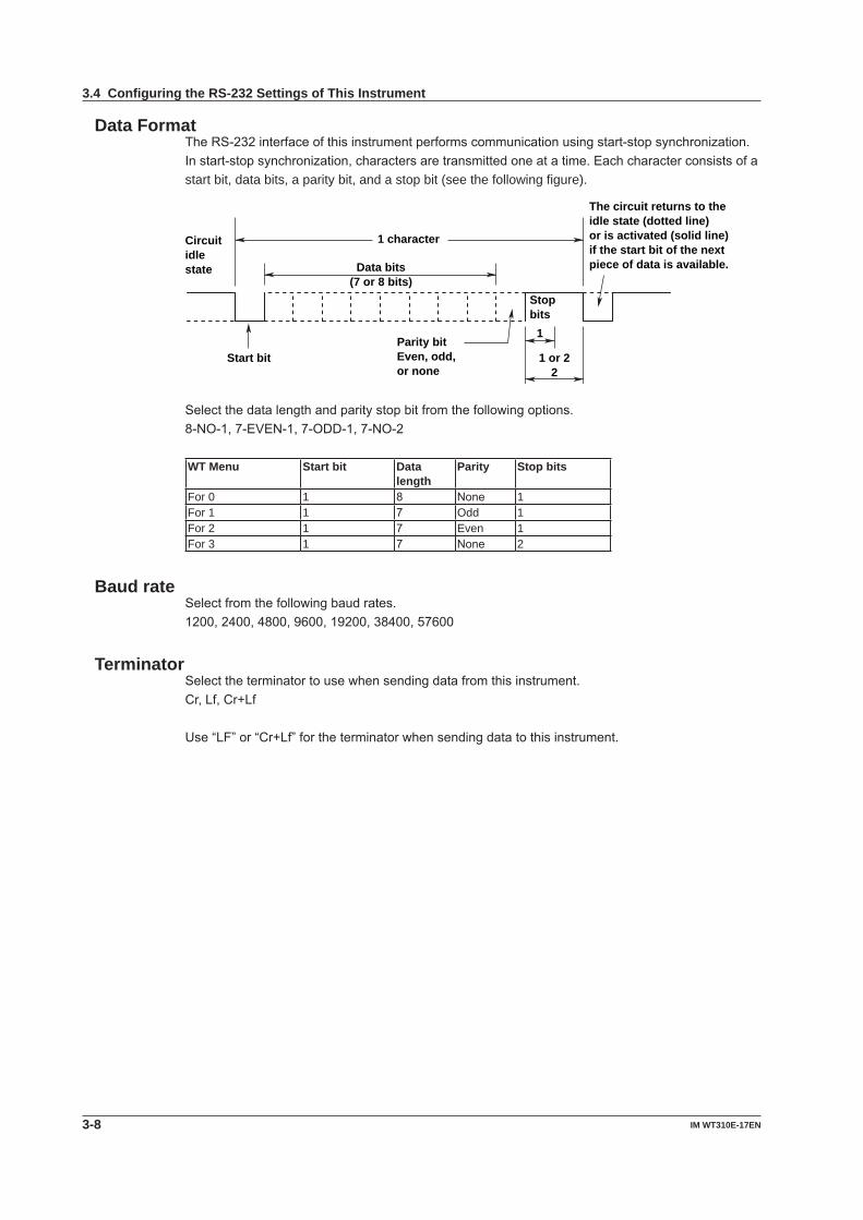
Data FormatTheRS-232interfaceofthisinstrumentperformscommunicationusingstart-stopsynchronization.Instart-stopsynchronization,charactersaretransmittedoneatatime.Eachcharacterconsistsofastart bit, data bits, a parity bit, and a stop bit (see the following figure).
Data bits(7 or 8 bits)
1 character
Stopbits
1
1 or 22
Parity bitEven, odd, or none
Start bit
Circuitidle state
The circuit returns to the idle state (dotted line)or is activated (solid line) if the start bit of the next piece of data is available.
Selectthedatalengthandparitystopbitfromthefollowingoptions.8-NO-1,7-EVEN-1,7-ODD-1,7-NO-2
WT Menu Start bit Data length
Parity Stop bits
For 0 1 8 None 1For 1 1 7 Odd 1For 2 1 7 Even 1For 3 1 7 None 2
Baud rateSelectfromthefollowingbaudrates.1200,2400,4800,9600,19200,38400,57600
TerminatorSelecttheterminatortousewhensendingdatafromthisinstrument.Cr,Lf,Cr+Lf
Use“LF”or“Cr+Lf”fortheterminatorwhensendingdatatothisinstrument.
3.4 Configuring the RS-232 Settings of This Instrument
4-1IM WT310E-17EN
Ethernet Interface
Chapter 4 Ethernet Interface
1
2
3
4
5
6
7
8
9
App
Index
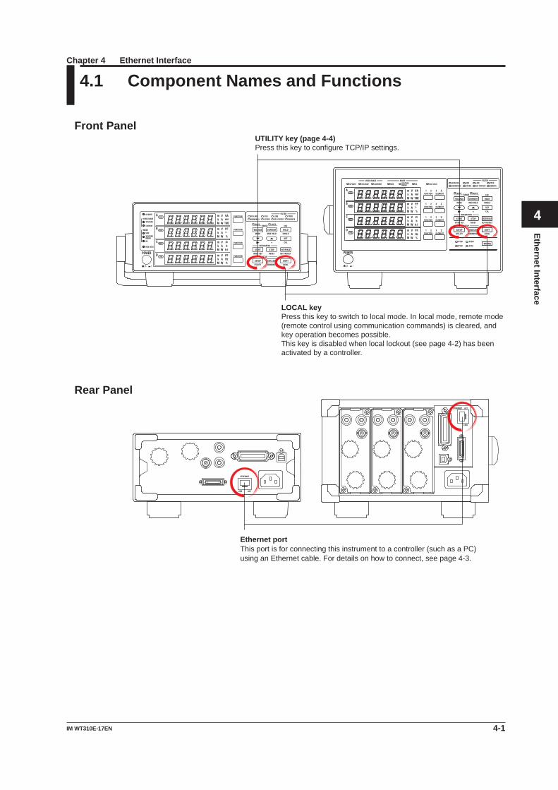
4.1 Component Names and Functions
Front Panel
LOCAL key Press this key to switch to local mode. In local mode, remote mode (remote control using communication commands) is cleared, and key operation becomes possible. This key is disabled when local lockout (see page 4-2) has been activated by a controller.
UTILITY key (page 4-4) Press this key to configure TCP/IP settings.
Rear Panel
Ethernet portThis port is for connecting this instrument to a controller (such as a PC) using an Ethernet cable. For details on how to connect, see page 4-3.
4-2 IM WT310E-17EN
4.2 Ethernet Interface Features and Specifications
Ethernet Interface FeaturesReception Feature• Youcanusethereceptionfeaturetospecifythesamesettingsthatyouspecifybyusingthefront
panel keys.• Outputrequestsformeasuredandcomputeddata,panelsetupparameters,anderrorcodescan
be received.
Transmission Feature• Thisinstrumentcantransmitmeasuredandcomputeddata.• Thisinstrumentcantransmitpanelsetupparametersandthestatusbyte.• Thisinstrumentcantransmiterrorcodeswhenerrorsoccur.
Ethernet Interface SpecificationsItem SpecificationsElectrical and mechanical IEEE802.3Simultaneousconnections 1Communication protocol TCP/IP(VXI-11,Modbus/TCP)Connector type RJ-45
Switching between Remote and Local ModesWhen Switching from Local to Remote ModeThis instrument switches to remote mode when it is in local mode and it receives a :COMMunicate:REMote ON command from the PC.• TheREMOTEindicatorilluminates.• AllkeysexcepttheSHIFT (LOCAL) key are disabled.• Settingsenteredinlocalmodeareretainedevenwhenthisinstrumentswitchestoremotemode.
When Switching from Remote to Local ModeWhenthisinstrumentisinremotemodeandyoupressSHIFT(LOCAL),thisinstrumentswitchestolocal mode. However, this does not work if this instrument has received a :COMMunicate:LOCKout ON command from the PC. This instrument switches to local mode when it receives a :COMMunicate:REMote OFF command from the PC, regardless of the local lockout state.• TheREMOTEindicatorturnsoff.• Keyoperationsareenabled.• Settingsenteredinremotemodeareretainedevenwhenthisinstrumentswitchestolocalmode.
NoteYoucannotusetheEthernetinterfacesimultaneouslywithotherinterfaces(GP-IB,RS-232,andUSB).
4-3IM WT310E-17EN
Ethernet Interface
1
2
3
4
5
6
7
8
9
App
Index
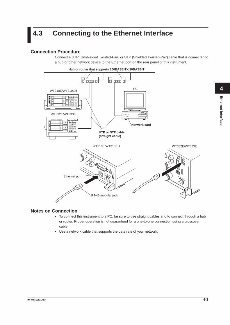
4.3 Connecting to the Ethernet Interface
Connection ProcedureConnectaUTP(UnshieldedTwisted-Pair)orSTP(ShieldedTwisted-Pair)cablethatisconnectedtoa hub or other network device to the Ethernet port on the rear panel of this instrument.
Hub or router that supports 100BASE-TX/10BASE-T
PC
UTP or STP cable (straight cable)
Network card
WT310E/WT310EH
WT332E/WT333E
WT310E/WT310EH WT332E/WT333E
Ethernet port
RJ-45 modular jack
Notes on Connection• ToconnectthisinstrumenttoaPC,besuretousestraightcablesandtoconnectthroughahub
orrouter.Properoperationisnotguaranteedforaone-to-oneconnectionusingacrossovercable.
• Useanetworkcablethatsupportsthedatarateofyournetwork.
4-4 IM WT310E-17EN
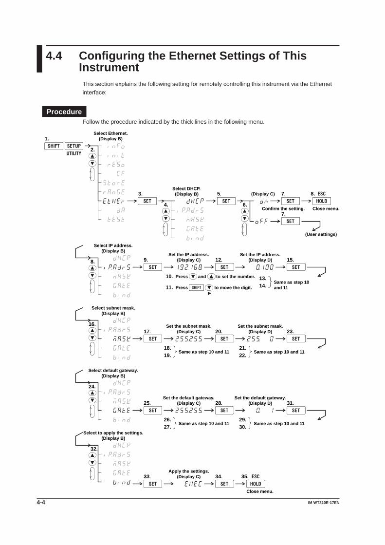
4.4 Configuring the Ethernet Settings of This Instrument
This section explains the following setting for remotely controlling this instrument via the Ethernet interface:
ProcedureFollow the procedure indicated by the thick lines in the following menu.
Select DHCP.(Display B)
4.
2.
Select Ethernet.(Display B)1.
3. 5.
6.
(Display C) 7.
Confirm the setting. Close menu.
(User settings)
7.
Select IP address.(Display B)
8. 9.Set the IP address.
(Display C) 12.
Press and to set the number.
Press to move the digit.
10.
11.
Set the IP address.(Display D)
13. 14.
Same as step 10 and 11
15.
Select subnet mask.(Display B)
16.17.
Set the subnet mask.(Display C) 20.
Set the subnet mask.(Display D)
21. 22.
Same as step 10 and 11
23.
18. 19.
Same as step 10 and 11
Select default gateway.(Display B)
24.
25.Set the default gateway.
(Display C) 28.Set the default gateway.
(Display D)
29. 30.
Same as step 10 and 11
31.
26. 27.
Same as step 10 and 11
Select to apply the settings.(Display B)
32.
33.Apply the settings.
(Display C) 34.
Close menu.
8.
35.
4-5IM WT310E-17EN
Ethernet Interface
1
2
3
4
5
6
7
8
9
App
Index
NoteOnlyuseonecommunicationinterface:USB,GP-IB,RS-232,orEthernet.Ifyousendcommandssimultaneously from more than one communication interface, this instrument will not execute the commands properly.
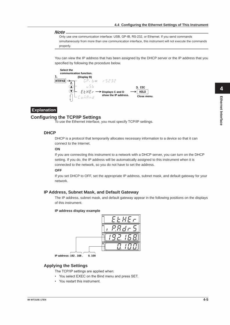
You can view the IP address that has been assigned by the DHCP server or the IP address that you specified by following the procedure below.
2.
Select the communication function.
1.
Displays C and D show the IP address. Close menu.
or
3.
(Display B)
ExplanationConfiguring the TCP/IP Settings
To use the Ethernet interface, you must specify TCP/IP settings.
DHCPDHCP is a protocol that temporarily allocates necessary information to a device so that it can connect to the Internet.ONIf you are connecting this instrument to a network with a DHCP server, you can turn on the DHCP setting. If you do, the IP address will be automatically assigned to this instrument when it is connected to the network, so you do not have to set the address.OFFIf you set DHCP to OFF, set the appropriate IP address, subnet mask, and default gateway for your network.
IP Address, Subnet Mask, and Default GatewayThe IP address, subnet mask, and default gateway appear in the following positions on the displays of this instrument.
IP address display example
IP address: 192 . 168 . 0. 100
Applying the SettingsTheTCP/IPsettingsareappliedwhen:• YouselectEXEContheBindmenuandpressSET.• Yourestartthisinstrument.
4.4 Configuring the Ethernet Settings of This Instrument
5-1IM WT310E-17EN
Programm
ing Overview
Chapter 5 Programming Overview
1
2
3
4
5
6
7
8
9
App
Index
,
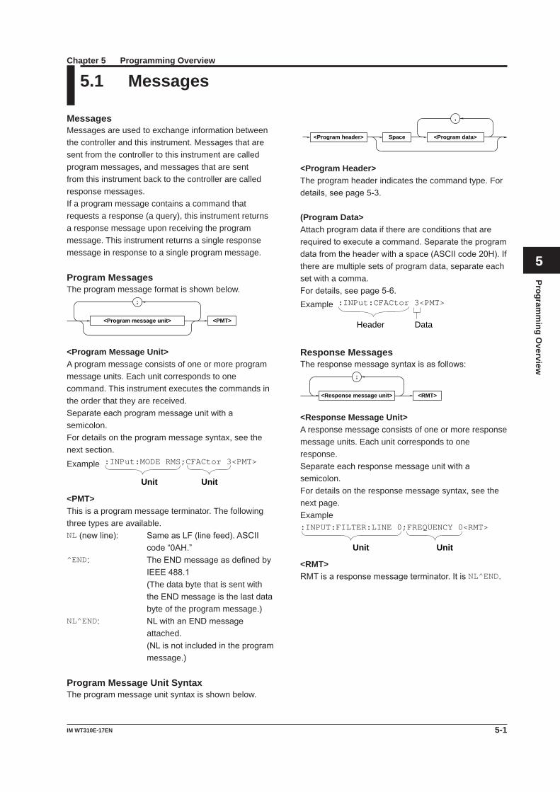
<Program header> <Program data>Space
<Program Header>The program header indicates the command type. For details,seepage5-3.
(Program Data>Attach program data if there are conditions that are requiredtoexecuteacommand.Separatetheprogramdatafromtheheaderwithaspace(ASCIIcode20H).Ifthere are multiple sets of program data, separate each set with a comma.Fordetails,seepage5-6.Example :INPut:CFACtor 3<PMT>
Header Data
Response MessagesTheresponsemessagesyntaxisasfollows:
<RMT>
;
<Response message unit>
<Response Message Unit>A response message consists of one or more response message units. Each unit corresponds to one response.Separateeachresponsemessageunitwithasemicolon.For details on the response message syntax, see the next page.Example
Unit Unit
:INPUT:FILTER:LINE 0;FREQUENCY 0<RMT>
<RMT>RMTisaresponsemessageterminator.ItisNL^END.
MessagesMessages are used to exchange information between the controller and this instrument. Messages that are sent from the controller to this instrument are called program messages, and messages that are sent from this instrument back to the controller are called response messages.If a program message contains a command that requests a response (a query), this instrument returns a response message upon receiving the program message. This instrument returns a single response message in response to a single program message.
Program MessagesThe program message format is shown below.
<PMT>
;
<Program message unit>
<Program Message Unit>A program message consists of one or more program message units. Each unit corresponds to one command. This instrument executes the commands in the order that they are received.Separateeachprogrammessageunitwithasemicolon.For details on the program message syntax, see the next section.
Example
Unit Unit
:INPut:MODE RMS;CFACtor 3<PMT>
<PMT>This is a program message terminator. The following three types are available.NL(newline): SameasLF(linefeed).ASCII
code“0AH.”^END: TheENDmessageasdefinedby
IEEE488.1 (The data byte that is sent with
theENDmessageisthelastdatabyte of the program message.)
NL^END: NLwithanENDmessageattached.
(NLisnotincludedintheprogrammessage.)
Program Message Unit SyntaxThe program message unit syntax is shown below.
5.1 Messages
5-2 IM WT310E-17EN
5.1 Messages
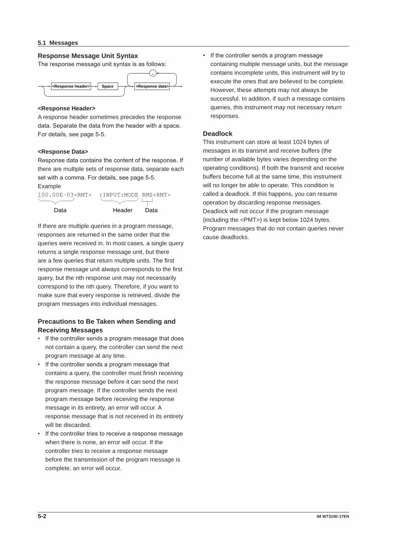
Response Message Unit SyntaxTheresponsemessageunitsyntaxisasfollows:
,
<Response header> <Response data>Space
<Response Header>A response header sometimes precedes the response data.Separatethedatafromtheheaderwithaspace.Fordetails,seepage5-5.
<Response Data>Responsedatacontainsthecontentoftheresponse.Ifthere are multiple sets of response data, separate each setwithacomma.Fordetails,seepage5-5.Example100.00E-03<RMT> :INPUT:MODE RMS<RMT>
HeaderData Data
If there are multiple queries in a program message, responses are returned in the same order that the queries were received in. In most cases, a single query returns a single response message unit, but there are a few queries that return multiple units. The first response message unit always corresponds to the first query, but the nth response unit may not necessarily correspond to the nth query. Therefore, if you want to make sure that every response is retrieved, divide the program messages into individual messages.
Precautions to Be Taken when Sending and Receiving Messages• Ifthecontrollersendsaprogrammessagethatdoes
not contain a query, the controller can send the next program message at any time.
• Ifthecontrollersendsaprogrammessagethatcontains a query, the controller must finish receiving the response message before it can send the next program message. If the controller sends the next program message before receiving the response message in its entirety, an error will occur. A response message that is not received in its entirety will be discarded.
• Ifthecontrollertriestoreceivearesponsemessagewhen there is none, an error will occur. If the controller tries to receive a response message before the transmission of the program message is complete, an error will occur.
• Ifthecontrollersendsaprogrammessagecontaining multiple message units, but the message contains incomplete units, this instrument will try to execute the ones that are believed to be complete. However, these attempts may not always be successful. In addition, if such a message contains queries, this instrument may not necessary return responses.
DeadlockThis instrument can store at least 1024 bytes of messages in its transmit and receive buffers (the number of available bytes varies depending on the operating conditions). If both the transmit and receive buffers become full at the same time, this instrument will no longer be able to operate. This condition is called a deadlock. If this happens, you can resume operation by discarding response messages.Deadlock will not occur if the program message (including the <PMT>) is kept below 1024 bytes. Program messages that do not contain queries never cause deadlocks.
5-3IM WT310E-17EN
Programm
ing Overview
1
2
3
4
5
6
7
8
9
App
Index
Example A portion of the commands from the integration command group
:INTEGrate?
:INTEGrate:MODE
:INTEGrate:TIMer
:INTEGrate:STARt
:INTEGrate:STOP
:INTEGrate:RESet
• WhenConcatenatingCommandsoftheSameGroup
This instrument stores the hierarchical level of the command that is currently being executed and processes the next command on the assumption that it belongs to the same level. Therefore, the common header section can be omitted for commands that belong to the same group.Example :INTEGrate:MODE NORMal;
TIMer 1,0,0<PMT>
• WhenConcatenatingCommandsofDifferentGroups
If the subsequent command does not belong to the same group, place a colon in front of the header (this colon cannot be omitted).Example :INTEGrate:MODE NORMal;:INPut:
MODE RMS<PMT>
• WhenConcatenatingSimpleHeaders If a simple header follows another command, place
a colon in front of the simple header (this colon cannot be omitted).Example :INTEGrate:MODE NORMal;:HOLD
ON<PMT>
• WhenConcatenatingCommonCommands Common commands that are defined in IEEE
488.2-1992areindependentofhierarchy.Acolonisnot needed before a common command.Example :INTEGrate:MODE NORMal;*CLS;:
INTEGrate:TIMer 1,0,0<PMT>
• WhenSeparatingCommandswith<PMT> If you separate two commands with a terminator,
two program messages will be sent. Therefore, the common header must be specified for each command even when commands belonging to the same command group are being concatenated.Example :INTEGrate:MODE NORMal<PMT>:
INTEGrate:TIMer 1,0,0<PMT>
5.2 Commands
CommandsThere are three types of commands (program headers) that a controller may send to this instrument. The commands differ in their program header formats.
Common Command HeaderCommandsthataredefinedinIEEE488.2-1992arecalled common commands. The common command headersyntaxisshownbelow.Besuretoincludeanasterisk (*) at the beginning of a common command.
* <Mnemonic> ?
Commoncommandexample:*CLS
Compound HeaderCommands, other than common commands, that are specific to this instrument are classified and arranged in a hierarchy according to their functions. The compoundheadersyntaxisshownbelow.Besuretouse a colon to specify a lower hierarchical level.
:
<Mnemonic> ?:
Compoundheaderexample::INPut:MODE
Simple HeaderThese commands are functionally independent and are not contained within a hierarchy. The format of a simple header is shown below.
<Mnemonic> ?:
Simpleheaderexample::HOLD
Note A <mnemonic> is an alphanumeric character string.
When Concatenating Commands• Command Groups A command group is a group of commands that
have common compound headers arranged in a hierarchy.Acommandgroupmaycontainsub-groups.
5-4 IM WT310E-17EN
5.2 Commands
Upper-level QueryAnupper-levelqueryisaquerythatismadebyappending a question mark to a command higher in the group. The controller can receive all of the settings in agroupcollectivelybyexecutingahighest-levelquery.Somequerygroupswhicharecomprisedofmorethanthree hierarchical levels can output all the lower level settings.Example :INTEGrate?<PMT> -> :INTEGRATE
:MODE NORMAL;TIMER 0,0,0<RMT>
Theresponsetoanupper-levelquerycanbesentback to this instrument as a program message. This enablesthesettingsthatwerepresentwhentheupper-level query was made to be reproduced later on. However,someupper-levelqueriesdonotreturnsetupparameters that are not currently in use. Exercise caution because not all of a group’s information is necessarily returned in a response.
Header Interpretation RulesThis instrument interprets the header that it receives according to the rules below.
• Mnemonicsarenotcasesensitive. Example “INPut”canalsobewrittenas“input”or
“INPUT.”• Thelower-casecharacterscanbeomitted. Example “INPut”canalsobewrittenas“INPu”or
“INP.”• Thequestionmarkattheendofaheaderindicates
that it is a query. You cannot omit the question mark. Example The shortest abbreviation for “INPut?”is
“INP?.”• Ifthe<x>(value)attheendofamnemonicis
omitted, it is interpreted as a 1. Example If “ELEMent”iswrittenas“ELEM,”
it means “ELEMent1.”• Partsofcommandsandparametersenclosedin
square brackets ([ ]) can be omitted. Example”[:INPut]:SCALing[:STATe] ON”can
be written as “SCAL ON.” However, the last section enclosed in square
bracketscannotbeomittedinanupper-levelquery. Example”SCALing?”and“SCALing:STATe?”are
different queries.
5-5IM WT310E-17EN
Programm
ing Overview
1
2
3
4
5
6
7
8
9
App
Index
5.3 Responses
ResponseWhen the controller sends a message unit that has a question mark in its program header (a query), this instrument returns a response message to the query. This instrument returns response messages in one of the following two forms.
• ResponseConsistingofaHeaderandData Responsesthatcanbeusedasprogrammessages
without any changes are returned with command headers attached.Example :INTEGrate:MODE?<PMT> ->
:INTEGRATE:MODE NORMAL<RMT>
• ResponseConsistingOnlyofData Responsesthatcannotbeusedasprogram
messagesunlesschangesaremade(query-onlycommands) are returned without headers. However, therearequery-onlycommandswhoseresponsesthis instrument will attach headers to.Example INTEGrate:STATe?<PMT> ->
RESET<RMT>
If You Want this instrument to Return Responses without HeadersYou can configure this instrument so that even responses that have both headers and data are returned without headers. Use the COMMunicate:HEADer command for this purpose.
Abbreviated FormThis instrument normally returns response headers with thelower-casesectionremoved.Youcanconfigurethisinstrument so that full headers are returned. Use the COMMunicate:VERBose command for this purpose. The sections enclosed in square brackets ([ ]) are also omitted in the abbreviated form.
5-6 IM WT310E-17EN
5.4 Data
• Ifavaluehasmoresignificantdigitsthanareavailable, the value will be rounded.
<Voltage>, <Current>, and <Time><Voltage>,<Current>,and<Time>indicatedecimalvalues that have physical significance. A <Multiplier> or <Unit> can be attached to the form that was described earlier. The following types of expressions are possible.
Form Example<NRf><Multiplier><Unit> 5MV
<NRf><Unit> 5E-3V
<NRf><Multiplier> 5M
<NRf> 5E-3
<Multiplier>Multipliers that you can use are indicated in the following table.
Symbol Word MultiplierEX Exa 1018
PE Peta 1015
T Tera 1012
G Giga 109
MA Mega 106
K Kilo 103
M Milli 10–3
U Micro 10–6
N Nano 10–9
P Pico 10–12
F Femto 10–15
<Unit>Units that you can use are indicated in the following table.
Symbol Word MeaningV Volt VoltageA Ampere CurrentS Second Time
• <Multiplier>and<Unit>arenotcasesensitive.• “U”isusedtoindicatemicro(”μ”).• “MA”isusedforMegatodistinguishitfromMilli.
However,“MA”isinterpretedasmilliampereforcurrent.
• Ifboth<Multiplier>and<Unit>areomitted,thebasicunit(V,A,orS)isused.
• Responsemessagesarealwaysexpressedinthe<NR3>form.Additionally,theyarereturnedinthebasic form, without a multiplier or unit attached.
DataData contains conditions and values that are written after the header. A space separates the data from the header.Dataisclassifiedasfollows:
Data Description<Decimal> A value expressed in decimal notation (Example:VTratiosetting ->[:INPut]:SCALing:VT 100)
<Voltage><Current> Aphysicalvalue<Time> (Example:Voltagerangesetting ->[:INPut]:VOLTage:RANge 150V)
<Register> Aregistervalueexpressedasbinary,octal,decimal, or hexadecimal
(Example:Extendedeventregistervalue ->:STATUS:EESE #HFE)<Character data> Predefined character string (mnemonic).
Selectfromtheavailablestringsinbraces. (Example:Measurementmodeselection ->[:INPut]:MODE {RMS|VMEan|DC})
<Boolean> Indicatesonandoff.SpecifyON,OFF,oravalue.
(Example:Turningdataholdon ->:HOLD ON)<Stringdata> Anarbitrarycharacterstring (Example:Modelcoderesponse ->:SYSTEM:MODEL "WT310E")
<Blockdata> Datathatcontains8-bitvalues (Example:Measureddata(binaryformat)response -> #40012ABCDEFGHIJKL)
<Decimal><Decimal> indicates a value expressed as a decimal number, as shown in the table below. Decimal values arewrittenintheNRformasspecifiedinANSIX3.42-1975.
Symbol Meaning Example<NR1> Integer 125 -1 +1000
<NR2> Fixed-pointnumber 125.0 -.90 +001.
<NR3> Floating-pointnumber 125.0E+0 -9E-1 +.1E4
<NRf> Anyoftheforms<NR1>to<NR3>
• Thisinstrumentcanreceivedecimalvaluesthataresentfromthecontrollerinanyoftheforms<NR1>to<NR3>.Thisisexpressedas<NRf>.
• Thisinstrumentreturnsaresponsetothecontrollerinoneoftheformsfrom<NR1>to<NR3>depending on the query. The same form is used regardless of the size of the value.
• Forthe<NR3>form,theplussignafterthe“E”canbe omitted. You cannot omit the minus sign.
• Ifavalueoutsidetherangeisentered,thevalueisadjustedtotheclosestvaluewithintherange.
5-7IM WT310E-17EN
Programm
ing Overview
5.4 Data
1
2
3
4
5
6
7
8
9
App
Index
• Ifacharacterstringcontainsadoublequotationmark ("), the double quotation mark is expressed as two consecutive quotation marks (""). This rule also applies to single quotation marks.
• Aresponsemessageisalwaysenclosedindoublequotation marks (").
• <Stringdata>isanycharacterstring.Therefore,theinstrument assumes that the remaining program message units are part of the character string if no closing single (') or double quotation mark (") is encountered. As a result, no error is detected if a quotation mark is omitted.
<Block Data><Blockdata>contains8-bitvalues.Itisonlyusedinresponse messages on this instrument. The syntax is asfollows:
Form Example#N<N-digitdecimalnumber> #800000010ABCDEFGHIJ <Data byte sequence>
• #N Indicatesthatthedatais<Blockdata>.Nindicates
the number of succeeding data bytes (digits) in ASCIIcode.
• <N-digitdecimalnumber> Indicatesthenumberofbytesofdata(example:
00000010 = 10 bytes).• <Databytesequence> Expressestheactualdata(example:ABCDEFGHIJ).• Dataiscomprisedof8-bitvalues(0to255).This
meansthattheASCIIcode“0AH,”whichstandsfor“NL,”canalsobeincludedinthedata.Hence,caremust be taken when programming the controller.
<Register><Register>indicatesaninteger,andcanbeexpressedin hexadecimal, octal, or binary as well as a decimal number. This is used when each bit of the value has a particular meaning. The following types of expressions are possible.
Form Example<NRf> 1
#H<Hexadecimalvaluemadeupof0to9andAtoF> #H0F#Q<Octalvaluemadeupof0to7> #Q777
#B<Binaryvaluemadeupof0and1> #B001100
• <Register>isnotcasesensitive.• Responsemessagesarealwaysexpressedinthe
<NR1>form.
<Character Data><Character Data> is a specified string of character data (a mnemonic). It is mainly used to indicate options andischosenfromthecharacterstringsgivenin{}.The data interpretation rules are the same as those describedin“HeaderInterpretationRules”onpage5-4.
Form Example{RMS|VMEan|DC} RMS
• Aswiththeheader,theCOMMunicate:VERBose command can be used to select whether to return the response in the full form or in the abbreviated form.
• TheCOMMunicate:HEADer setting does not affect <Character data>.
<Boolean><Boolean>isdatathatindicatesONorOFF.Thefollowing types of expressions are possible.
Form Example{ON|OFF|<NRf>} ON OFF 1 0
• When<NRf>isexpressedintheform,“OFF”isselectediftheroundedintegervalueis0,and“ON”is selected for all other cases.
• Aresponsemessageisalwaysreturnedwitha1ifthevalueisONandwitha0ifthevalueisOFF.
<String Data><Stringdata>isnotaspecifiedcharacterstringlike<Character data>. It is an arbitrary character string. The character string must be enclosed in single quotation marks (') or double quotation marks (").
Form Example<Stringdata> 'ABC' "IEEE488.2-1992"
5-8 IM WT310E-17EN
5.5 Synchronization with the Controller
The STATus:FILTer1 FALL command sets the transition filter so that bit 0 in the extended event (FILTer1) is set to 1 when bit 0 in the condition register changes from 1 to 0, in other words when the updating of measured data is finished.
The STATus:EESE 1 command is used to only change the status byte based on bit 0 in the extended event register.
The STATus:EESR? command is used to clear the extended event register.
The *SRE 8 command is used to generate service requests based only on the changes in the extended event register bits.
The :NUMeric[:NORMal]:VALue? command is not executed until a service request is generated.
• UsingtheCOMMunicate:WAITCommand The COMMunicate:WAIT command is used to wait
for a specific event to occur.Example :STATus:FILTer1 FALL;:STATus:
EESR?<PMT>
(ReadtheresponsetoSTATus:EESR?) Loop
COMMunicate:WAIT 1<PMT>
:NUMeric[:NORMal]:VALue?<PMT>
(Readtheresponseto:NUMeric[]NORMal]:VALue?)
:STATus:EESR?<PMT>
(ReadtheresponsetoSTATus:EESR?) (ReturntoLoop)
For a description of STATus:FILTer1 FALL and STATus:EESR?, see the previous section about the extended event register.
The COMMunicate:WAIT 1 command specifies that the program will wait for bit 0 in the extended event register to be set to 1.
:NUMeric[:NORMal]:VALue? is not executed until bit 0 in the extended event register becomes 1.
Overlap and Sequential CommandsTherearetwotypesofcommands:overlapandsequential. With overlap commands, the execution of the next command may start before the execution of the previous command is finished. With sequential commands, the execution of the next command is held until the execution of the previous command is finished (even if multiple commands are sent consecutively).All commands of this instrument are sequential commands. Even when only sequential commands are available, there are times when it is necessary to achieve synchronization to properly query the measured data. For example, if you want to query the most recent numeric data each time that the measured data is updated, you can attempt to do this by sending the :NUMeric[:NORMal]:VALue? command with some arbitrary timing. However, because this instrument returns the current measured data regardless of whether the measured data has been updated since the previous query, this method may return data that is the same as the previous data. If this happens, you must use the following method to synchronize with the end of measured data updating.
• UsingtheSTATus:CONDition?Query STATus:CONDition? is used to query the contents
oftheconditionregister(seepage7-5).Youcandetermine whether the measured data is being updated by reading bit 0 of the condition register. If bit 0 of the condition register is 1, the measured data is being updated. If it is 0, the measured data can be queried.
However, in the case of this instrument, it is difficult to determine the updating of measured data with STATus:CONDition? because the period during which bit 0 of the condition register remains at 1 is very short.
• UsingtheExtendedEventRegister The changes in the condition register can be
reflected in the extended event register (see page 6-5fordetails).Example :STATus:FILTer1 FALL;:STATus:
EESE 1;EESR?;*SRE 8<PMT> (ReadtheresponsetoSTATus:EESR?) Loop (Wait for a service request) :NUMeric[:NORMal]:VALue?<PMT> (Readtheresponseto:
NUMeric[]NORMal]:VALue?) :STATus:EESR?<PMT> (ReadtheresponsetoSTATus:EESR?) (ReturntoLoop)
6-1IM WT310E-17EN
Com
mands
Chapter 6 Commands
1
2
3
4
5
6
7
8
9
App
Index
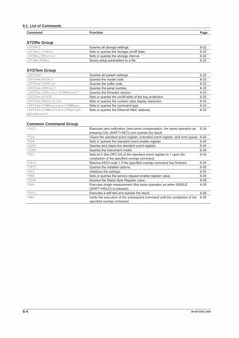
6.1 List of Commands
Command Function Page AOUTput Group:AOUTput? QueriesallD/Aoutputsettings. 6-5:AOUTput[:NORMal]:PRESet SetstheD/Aoutputitemstotheirdefaultvalues. 6-5:AOUTput[:NORMal]:CHANnel<x> SetsorqueriesaD/Aoutputitem(functionorelement). 6-5:AOUTput[:NORMal]:IRTime SetsorqueriestheratedintegrationtimethatisusedintheD/Aoutputofthe
integrated value.6-5
:AOUTput[:NORMal]:MODE<x> SetsorqueriesaD/Arangemode. 6-5:AOUTput[:NORMal]:RATE<x> SetsorqueriesthemaximumandminimumvaluesforwhentheD/Aoutput
isinmanualrangemode.Setsorqueriesthecomparisonupperandlowerlimits for when the D/A output is in comparator mode.
6-6
COMMunicate group:COMMunicate? Queriesallcommunicationsettings. 6-7:COMMunicate:HEADer Setsorquerieswhetherheadersareattachedtoqueryresponses. 6-7:COMMunicate:LOCKout Sets/clearslocallockout. 6-7:COMMunicate:REMote Setsthisinstrumenttoremoteorlocalmode.ONisremotemode. 6-7:COMMunicate:STATus? Queriestheline-specificstatus. 6-7:COMMunicate:VERBose Setsorquerieswhethertheresponsetoaqueryisreturnedfullyspelledout
or in its abbreviated form.6-7
:COMMunicate:WAIT Waits for a specified extended event to occur. 6-7:COMMunicate:WAIT? Creates the response that is returned when a specified extended event
occurs.6-7
DISPlay group:DISPlay? Queriesalldisplaysettings. 6-8:DISPlay:NORMal? Queriesallnormalmeasurementdatadisplaysettings. 6-8:DISPlay[:NORMal]:ITEM<x> Setsorqueriesanormalmeasurementdatadisplayitem. 6-8:DISPlay:HARMonics? Queriesallharmonicmeasurementdatadisplaysettings. 6-8:DISPlay:HARMonics:ITEM<x> Setsorqueriesaharmonicmeasurementdatadisplayitem. 6-8 HARMonics Group:HARMonics? Queriesallharmonicmeasurementsettings. 6-10:HARMonics:PLLSource SetsorqueriesthePLLsource. 6-10:HARMonics:ORDer Setsorqueriesthemaximumandminimumharmonicordersthatare
analyzed.6-10
:HARMonics:THD SetsorqueriestheequationusedtocomputetheTHD(totalharmonicdistortion).
6-10
:HARMonics:DISPlay? Queriesallharmonicmeasurementdisplaysettings. 6-10:HARMonics:DISPlay[:STATe] Setsorqueriestheon/offstateofharmonicmeasurementdatadisplay. 6-10:HARMonics:DISPlay:ORDer Setsorqueriestheharmonicorderoftheharmoniccomponentthatisshown
indisplayBfortheharmonicmeasurementdatadisplay.6-10
HOLD Group:HOLD Setsorqueriestheon/offstateoftheoutputholdfeaturefordisplay,
communication, and other types of data.6-11
INPut Group:INPut? Queriesallinputsettings. 6-12[:INPut]:CFACtor Setsorqueriesthecrestfactor. 6-12[:INPut]:WIRing Setsorqueriesthewiringsystem. 6-12[:INPut]:MODE Setsorqueriesthevoltageandcurrentmeasurementmode. 6-12[:INPut]:VOLTage? Queriesallvoltagemeasurementsettings. 6-12[:INPut]:VOLTage:RANGe Setsorqueriesthevoltagerange. 6-12[:INPut]:VOLTage:AUTO Setsorqueriesthevoltageautorangeon/offstate. 6-12[:INPut]:VOLTage:CONFig Setsorqueriesthevalidvoltagerange. 6-12
6-2 IM WT310E-17EN
6.1 List of Commands
Command Function Page[:INPut]:VOLTage:POJump Setsorqueriesthejumpdestinationrangethatisusedwhenavoltagepeak
over-rangeoccurs.6-13
[:INPut]:CURRent? Queriesallelectriccurrentmeasurementsettings. 6-13[:INPut]:CURRent:RANGe Setsorqueriesthecurrentrange. 6-13[:INPut]:CURRent:AUTO Setsorqueriesthecurrentautorangeon/offstate. 6-13[:INPut]:CURRent:CONFig Setsorqueriesthevalidcurrentrange. 6-13[:INPut]:CURRent:POJump Setsorqueriesthejumpdestinationrangethatisusedwhenacurrentpeak
over-rangeoccurs.6-13
[:INPut]:CURRent:EXTSensor: CONFig
Setsorqueriesthevalidexternalcurrentsensorrange. 6-13
[:INPut]:CURRent:EXTSensor: POJump
Setsorqueriesthejumpdestinationrangethatisusedwhenacurrentpeakover-rangeoccurs.
6-14
[:INPut]:CURRent:SRATio? Queriestheexternalcurrentsensorconversionratiosofallelements. 6-14[:INPut]:CURRent:SRATio[:ALL] Collectively sets the external current sensor conversion ratios of all elements. 6-14[:INPut]:CURRent:SRATio: ELEMent<x>
Setsorqueriestheexternalcurrentsensorconversionratioofthespecifiedelement.
6-14
[:INPut]:RCONfig Setsorqueriestheon/offstateoftherangeconfiguration(validrangeselection) feature.
6-14
[:INPut]:SCALing? Queriesallscalingsettings. 6-14[:INPut]:SCALing[:STATe] Setsorqueriesthescalingon/offstate. 6-14[:INPut]: SCALing:{VT|CT|SFACtor}?
QueriestheVTratios,CTratios,orpowercoefficientsofallelements. 6-14
[:INPut]: SCALing:{VT|CT|SFACtor}[:ALL]
CollectivelysetstheVTratio,CTratio,orpowercoefficientofallelements. 6-14
[:INPut]: SCALing:{VT|CT|SFACtor}: ELEMent<x>
SetsorqueriestheVTratio,CTratio,orpowercoefficientofthespecifiedelement.
6-14
[:INPut]:SYNChronize Setsorqueriesthesynchronizationsource. 6-14[:INPut]:FILTer? Queriesallinputfiltersettings. 6-15[:INPut]:FILTer:LINE Setsorqueriesthelinefilter. 6-15[:INPut]:FILTer:FREQuency Setsorqueriesthefrequencyfilter. 6-15[:INPut]:POVer? Queriesthepeakover-rangeinformation. 6-15[:INPut]:CRANge? Setsorqueriesthecheckrangestatus. 6-15 INTEGrate Group:INTEGrate? Queriesallintegrationsettings. 6-16:INTEGrate:MODE Setsorqueriestheintegrationmode. 6-16:INTEGrate:TIMer Setsorqueriestheintegrationtimervalue. 6-16:INTEGrate:STARt Startsintegration. 6-16:INTEGrate:STOP Stopsintegration. 6-16:INTEGrate:RESet Resetstheintegratedvalue. 6-16:INTEGrate:STATe? Queriestheintegrationstatus. 6-16 MATH Group:MATH SetsorqueriestheMATHequation. 6-17 MEASure Group:MEASure? Queriesallmeasuredandcomputeddataoutputsettings. 6-18:MEASure:AVERaging? Queriesallaveragingsettings. 6-18:MEASure:AVERaging[:STATe] Setsorqueriestheon/offstateofaveraging. 6-18:MEASure:AVERaging:TYPE Setsorqueriestheaveragingtype. 6-18:MEASure:AVERaging:COUNt Setsorqueriestheaveragingcoefficient. 6-18:MEASure:MHOLd SetstheMAXholdon/offstate. 6-18
6-3IM WT310E-17EN
Com
mands
6.1 List of Commands
1
2
3
4
5
6
7
8
9
App
Index
Command Function Page NUMeric Group:NUMeric? Queriesallnumericdataoutputsettings. 6-19:NUMeric:FORMat Setsorqueriesthenumericdataformat. 6-19:NUMeric:NORMal? Queriesallnumericdataoutputsettings. 6-19:NUMeric[:NORMal]:VALue? Queriesthenumericdata. 6-19:NUMeric[:NORMal]:NUMber Setsorqueriesthenumberofnumericdataitemsthataretransmittedbythe
:NUMeric[:NORMal]:VALue?command.6-19
:NUMeric[:NORMal]:ITEM<x> Setsorqueriesthespecifiednumericdataoutputitem(function,element,and harmonic order).
6-20
:NUMeric[:NORMal]:PRESet Presets the numeric data output item pattern. 6-20:NUMeric[:NORMal]:CLEar Clearsnumericdataoutputitems(setstheitemstoNONE). 6-20:NUMeric[:NORMal]:DELete Deletes numeric data output items. 6-20:NUMeric[:NORMal]:HEADer? Queriesthenumericdataheader. 6-20:NUMeric:LIST? Queriesallharmonicmeasurementnumericlistdataoutputsettings. 6-21:NUMeric:LIST:VALue? Queriestheharmonicmeasurementnumericlistdata. 6-21:NUMeric:LIST:NUMber Setsorqueriesthenumberofnumericlistdataitemsthataretransmittedby
:NUMeric:LIST:VALue?.6-21
:NUMeric:LIST:ORDer Setsorqueriesthemaximumoutputharmonicorderoftheharmonicmeasurement numeric list data.
6-21
:NUMeric:LIST:SELect Setsorqueriestheoutputcomponentsoftheharmonicmeasurementnumeric list data.
6-21
:NUMeric:LIST:ITEM<x> Setsorqueriestheoutputitem(functionandelement)ofthespecifiedharmonic measurement numeric list data item.
6-22
:NUMeric:LIST:PRESet Presets the harmonic measurement numeric list data output item pattern. 6-22:NUMeric:LIST:CLEar Clears harmonic measurement numeric list data output items (sets the items
toNONE).6-22
:NUMeric:LIST:DELete Deletes harmonic measurement numeric list data output items. 6-22:NUMeric:HOLD Setsorqueriestheon/off(hold/release)statusofthenumericdatahold
feature.6-23
RATE Group:RATE Setsorqueriesthedataupdateinterval. 6-29:RATE:AUTO? Queriesallapplicablesettingsforwhenthedataupdateintervalissetto
Auto.6-29
:RATE:AUTO:TIMeout SetsorqueriesthetimeoutforwhenthedataupdateintervalissettoAuto. 6-29:RATE:AUTO:SYNChronize Setsorqueriesthesynchronizationsourceforwhenthedataupdateinterval
is set to Auto.6-29
RECall Group:RECall:NUMber? Queriesthenumberofblocksofmeasureddatathatisstored. 6-30:RECall[:NORMal]:VALue? Queriesthenumericdataatthespecifiedblocknumber. 6-30:RECall:LIST:VALue? Queriesthenumericlistdataofharmonicmeasurementatthespecified
block number.6-30
:RECall:PANel Loads a setup parameter file. 6-30 STATus group:STATus? Queriesallthesettingsforthecommunicationstatusfeature. 6-31:STATus:CONDition? Queriesthecontentsoftheconditionregister. 6-31:STATus:EESE Setsorqueriestheextendedeventenableregister. 6-31:STATus:EESR? Queriesthecontentsoftheextendedeventregisterandclearstheregister. 6-31:STATus:ERRor? Queriestheerrorcodeandmessageofthelasterrorthathasoccurred(top
of the error queue).6-31
:STATus:FILTer<x> Setsorqueriesthetransitionfilter. 6-31:STATus:QENable Setsorquerieswhethermessagesotherthanerrorswillbestoredtothe
errorqueue(ON)ornot(OFF).6-31
:STATus:QMESsage SetsorquerieswhethermessageinformationwillbeattachedtotheresponsetotheSTATus:ERRor?query(ON/OFF).
6-31
:STATus:SPOLl? Executes serial polling. 6-31
6-4 IM WT310E-17EN
6.1 List of Commands
Command Function Page STORe Group:STORe? Queriesallstoragesettings. 6-32:STORe[:STATe] Setsorqueriesthestorageon/offstate. 6-32:STORe:INTerval Setsorqueriesthestorageinterval. 6-32:STORe:PANel Savessetupparameterstoafile. 6-32 SYSTem Group:SYSTem? Queriesallsystemsettings. 6-33:SYSTem:MODel? Queriesthemodelcode. 6-33:SYSTem:SUFFix? Queriesthesuffixcode. 6-33:SYSTem:SERial? Queriestheserialnumber. 6-33:SYSTem:VERsion[:FIRMware]? Queriesthefirmwareversion. 6-33:SYSTem:KLOCk Setsorqueriestheon/offstateofthekeyprotection. 6-33:SYSTem:RESolution Setsorqueriesthenumericdatadisplayresolution. 6-33:SYSTem:COMMunicate:COMMand Setsorqueriesthecommandtype. 6-33:SYSTem:COMMunicate:ETHernet: MACaddress?
SetsorqueriestheEthernetMACaddress. 6-33
Common Command Group*CAL? Executeszerocalibration(zero-levelcompensation,thesameoperationas
pressingCAL(SHIFT+SET))andqueriestheresult.6-34
*CLS Clears the standard event register, extended event register, and error queue. 6-34*ESE Setsorqueriesthestandardeventenableregister. 6-34*ESR? Queriesandclearsthestandardeventregister. 6-34*IDN? Queriestheinstrumentmodel. 6-34*OPC Setsbit0(theOPCbit)ofthestandardeventregisterto1uponthe
completion of the specified overlap command.6-34
*OPC? ReturnsASCIIcode1ifthespecifiedoverlapcommandhasfinished. 6-35*OPT? Queriestheinstalledoptions. 6-35*RST Initializes the settings. 6-35*SRE Setsorqueriestheservicerequestenableregistervalue. 6-35*STB? QueriestheStatusByteRegistervalue. 6-35*TRG Executessinglemeasurement(thesameoperationaswhenSINGLE
(SHIFT+HOLD)ispressed).6-35
*TST? Executesaself-testandqueriestheresult. 6-36*WAI Holds the execution of the subsequent command until the completion of the
specified overlap command.6-36
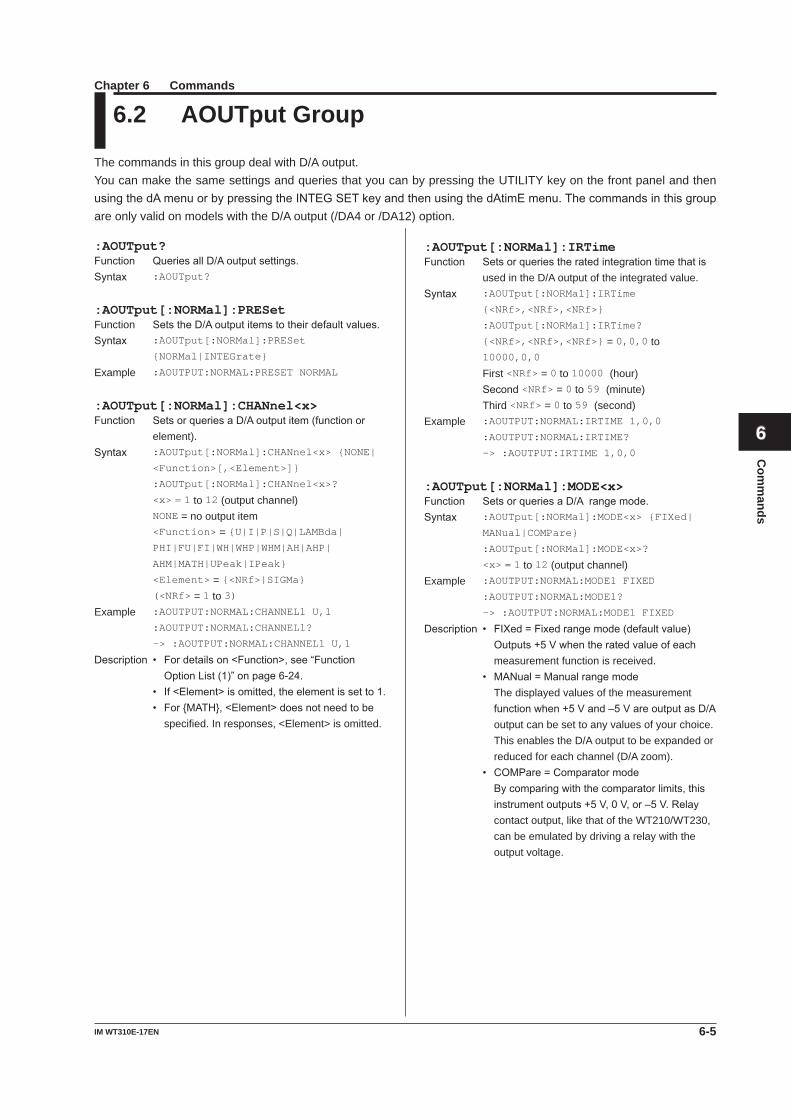
6-5IM WT310E-17EN
Com
mands
1
2
3
4
5
6
7
8
9
App
Index
:AOUTput?Function QueriesallD/Aoutputsettings.Syntax :AOUTput?
:AOUTput[:NORMal]:PRESetFunction SetstheD/Aoutputitemstotheirdefaultvalues.Syntax :AOUTput[:NORMal]:PRESet
{NORMal|INTEGrate}
Example :AOUTPUT:NORMAL:PRESET NORMAL
:AOUTput[:NORMal]:CHANnel<x>Function SetsorqueriesaD/Aoutputitem(functionor
element).Syntax :AOUTput[:NORMal]:CHANnel<x> {NONE|
<Function>[,<Element>]}
:AOUTput[:NORMal]:CHANnel<x>?
<x> = 1 to 12 (output channel) NONE = no output item
<Function> = {U|I|P|S|Q|LAMBda| PHI|FU|FI|WH|WHP|WHM|AH|AHP|
AHM|MATH|UPeak|IPeak}
<Element> = {<NRf>|SIGMa} (<NRf> = 1 to 3)
Example :AOUTPUT:NORMAL:CHANNEL1 U,1
:AOUTPUT:NORMAL:CHANNEL1?
-> :AOUTPUT:NORMAL:CHANNEL1 U,1
Description • Fordetailson<Function>,see“FunctionOptionList(1)”onpage6-24.
• If<Element>isomitted,theelementissetto1. • For{MATH},<Element>doesnotneedtobe
specified. In responses, <Element> is omitted.
6.2 AOUTput Group
The commands in this group deal with D/A output.You can make the same settings and queries that you can by pressing the UTILITY key on the front panel and then usingthedAmenuorbypressingtheINTEGSETkeyandthenusingthedAtimEmenu.Thecommandsinthisgroupare only valid on models with the D/A output (/DA4 or /DA12) option.
:AOUTput[:NORMal]:IRTimeFunction Setsorqueriestheratedintegrationtimethatis
used in the D/A output of the integrated value.Syntax :AOUTput[:NORMal]:IRTime
{<NRf>,<NRf>,<NRf>}
:AOUTput[:NORMal]:IRTime?
{<NRf>,<NRf>,<NRf>} = 0,0,0 to 10000,0,0
First <NRf> = 0 to 10000 (hour) Second<NRf> = 0 to 59 (minute) Third <NRf> = 0 to 59 (second)
Example :AOUTPUT:NORMAL:IRTIME 1,0,0
:AOUTPUT:NORMAL:IRTIME?
-> :AOUTPUT:IRTIME 1,0,0
:AOUTput[:NORMal]:MODE<x>Function SetsorqueriesaD/Arangemode.Syntax :AOUTput[:NORMal]:MODE<x> {FIXed|
MANual|COMPare}
:AOUTput[:NORMal]:MODE<x>?
<x> = 1 to 12 (output channel)Example :AOUTPUT:NORMAL:MODE1 FIXED
:AOUTPUT:NORMAL:MODE1?
-> :AOUTPUT:NORMAL:MODE1 FIXED
Description • FIXed=Fixedrangemode(defaultvalue) Outputs+5Vwhentheratedvalueofeach
measurement function is received. • MANual=Manualrangemode The displayed values of the measurement
functionwhen+5Vand–5VareoutputasD/Aoutput can be set to any values of your choice. This enables the D/A output to be expanded or reduced for each channel (D/A zoom).
• COMPare=Comparatormode Bycomparingwiththecomparatorlimits,this
instrumentoutputs+5V,0V,or–5V.Relaycontact output, like that of the WT210/WT230, can be emulated by driving a relay with the output voltage.
Chapter 6 Commands
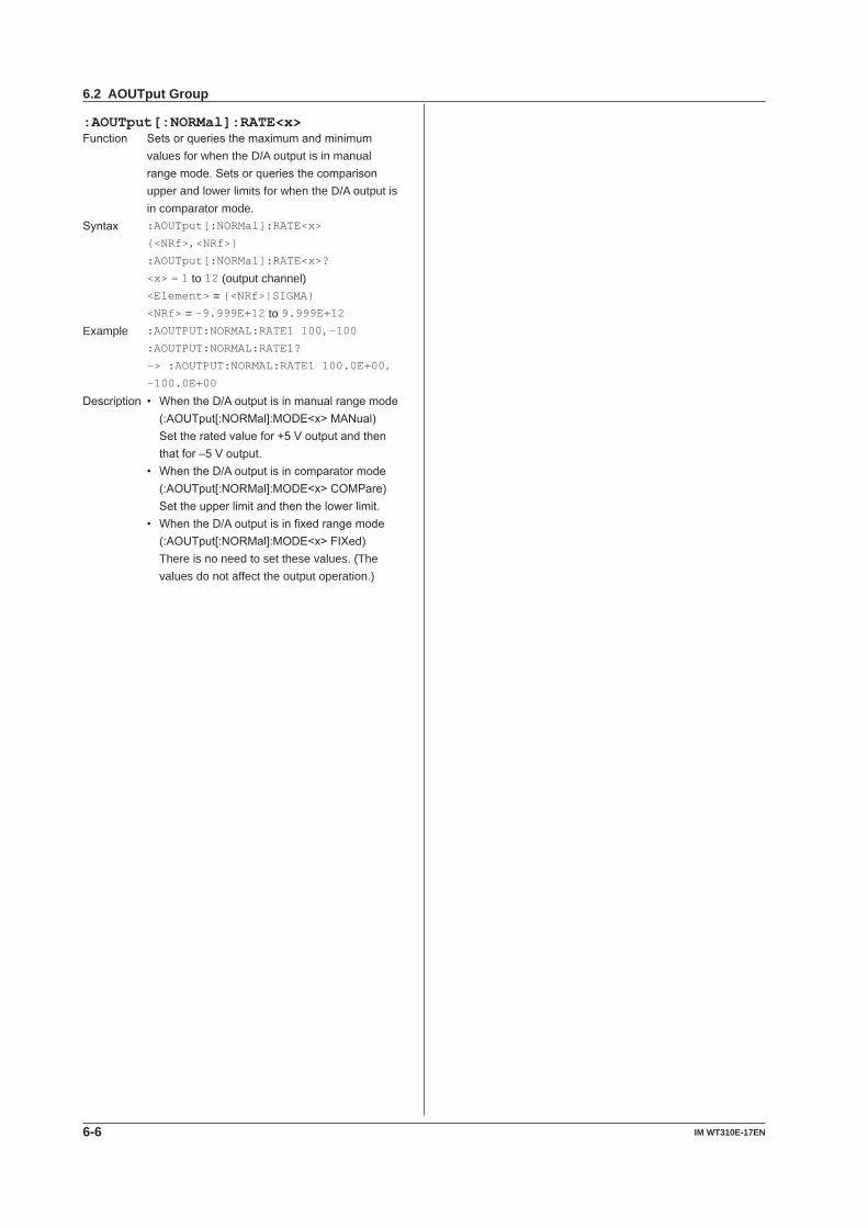
6-6 IM WT310E-17EN
:AOUTput[:NORMal]:RATE<x>Function Setsorqueriesthemaximumandminimum
values for when the D/A output is in manual rangemode.Setsorqueriesthecomparisonupper and lower limits for when the D/A output is in comparator mode.
Syntax :AOUTput[:NORMal]:RATE<x>
{<NRf>,<NRf>}
:AOUTput[:NORMal]:RATE<x>?
<x> = 1 to 12 (output channel) <Element> = {<NRf>|SIGMA} <NRf> = -9.999E+12 to 9.999E+12
Example :AOUTPUT:NORMAL:RATE1 100,-100
:AOUTPUT:NORMAL:RATE1?
-> :AOUTPUT:NORMAL:RATE1 100.0E+00,
-100.0E+00
Description • WhentheD/Aoutputisinmanualrangemode(:AOUTput[:NORMal]:MODE<x>MANual)
Settheratedvaluefor+5Voutputandthenthatfor–5Voutput.
• WhentheD/Aoutputisincomparatormode(:AOUTput[:NORMal]:MODE<x>COMPare)
Settheupperlimitandthenthelowerlimit. • WhentheD/Aoutputisinfixedrangemode
(:AOUTput[:NORMal]:MODE<x>FIXed) There is no need to set these values. (The
values do not affect the output operation.)
6.2 AOUTput Group
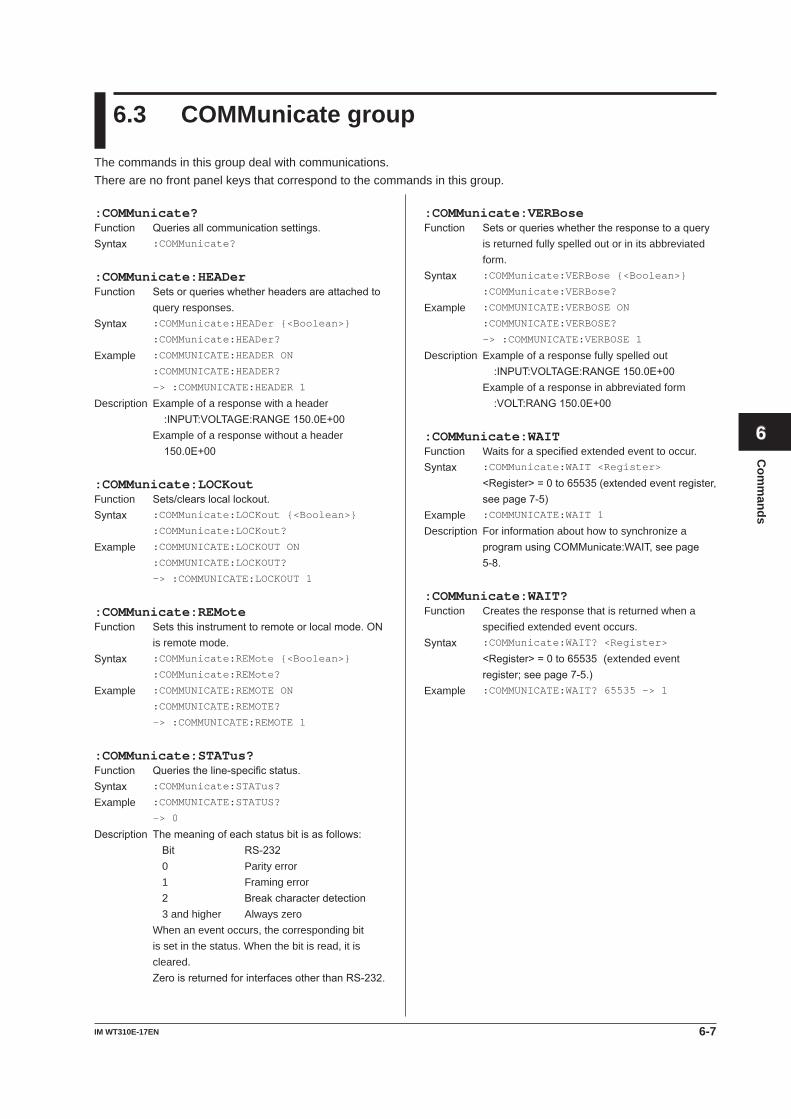
6-7IM WT310E-17EN
Com
mands
1
2
3
4
5
6
7
8
9
App
Index
6.3 COMMunicate group
The commands in this group deal with communications.There are no front panel keys that correspond to the commands in this group.
:COMMunicate?Function Queriesallcommunicationsettings.Syntax :COMMunicate?
:COMMunicate:HEADerFunction Setsorquerieswhetherheadersareattachedto
query responses.Syntax :COMMunicate:HEADer {<Boolean>}
:COMMunicate:HEADer?
Example :COMMUNICATE:HEADER ON
:COMMUNICATE:HEADER?
-> :COMMUNICATE:HEADER 1
Description Example of a response with a header :INPUT:VOLTAGE:RANGE150.0E+00 Example of a response without a header 150.0E+00
:COMMunicate:LOCKoutFunction Sets/clearslocallockout.Syntax :COMMunicate:LOCKout {<Boolean>}
:COMMunicate:LOCKout?
Example :COMMUNICATE:LOCKOUT ON
:COMMUNICATE:LOCKOUT?
-> :COMMUNICATE:LOCKOUT 1
:COMMunicate:REMoteFunction Setsthisinstrumenttoremoteorlocalmode.ON
is remote mode.Syntax :COMMunicate:REMote {<Boolean>}
:COMMunicate:REMote?
Example :COMMUNICATE:REMOTE ON
:COMMUNICATE:REMOTE?
-> :COMMUNICATE:REMOTE 1
:COMMunicate:STATus?Function Queriestheline-specificstatus.Syntax :COMMunicate:STATus?
Example :COMMUNICATE:STATUS?
-> 0
Description Themeaningofeachstatusbitisasfollows: Bit RS-232 0 Parity error 1 Framing error 2 Breakcharacterdetection 3 and higher Always zero When an event occurs, the corresponding bit
is set in the status. When the bit is read, it is cleared.
ZeroisreturnedforinterfacesotherthanRS-232.
:COMMunicate:VERBoseFunction Setsorquerieswhethertheresponsetoaquery
is returned fully spelled out or in its abbreviated form.
Syntax :COMMunicate:VERBose {<Boolean>}
:COMMunicate:VERBose?
Example :COMMUNICATE:VERBOSE ON
:COMMUNICATE:VERBOSE?
-> :COMMUNICATE:VERBOSE 1
Description Example of a response fully spelled out :INPUT:VOLTAGE:RANGE150.0E+00 Example of a response in abbreviated form :VOLT:RANG150.0E+00
:COMMunicate:WAITFunction Waits for a specified extended event to occur.Syntax :COMMunicate:WAIT <Register>
<Register>=0to65535(extendedeventregister,seepage7-5)
Example :COMMUNICATE:WAIT 1
Description For information about how to synchronize a programusingCOMMunicate:WAIT,seepage5-8.
:COMMunicate:WAIT?Function Creates the response that is returned when a
specified extended event occurs.Syntax :COMMunicate:WAIT? <Register>
<Register>=0to65535 (extended event register;seepage7-5.)
Example :COMMUNICATE:WAIT? 65535 -> 1
6-8 IM WT310E-17EN
:DISPlay?Function Queriesalldisplay settings.Syntax :DISPlay?
:DISPlay:NORMal?Function Queriesallnormalmeasurementdatadisplay
settings.Syntax :DISPlay:NORMal?
:DISPlay[:NORMal]:ITEM<x>Function Setsorqueriesanormalmeasurementdata
display item.Syntax :DISPlay[:NORMal]:ITEM<x> <Function>
[,<Element>]}
:DISPlay[:NORMal]:ITEM<x>?
<x> = 1 to 4 (display) Function of display A (<x>=1) <Function> = {U|I|P|S|Q|TIME} FunctionofdisplayB(<x>=2) <Function> = {U|I|P|LAMBda|PHI} Function of display C (<x>=3) <Function> = {U|I|P|UPPeak|UMPeak|
IPPeak|IMPeak|PPPeak|PMPeak|WH|
WHP|WHM|AH|AHP|AHM|MATH}
Function of display D (<x>=4) <Function> = {U|I|P|LAMBda|FU|FI|
UTHD|ITHD}
<Element> = {<NRf>|SIGMa} (<NRf> = 1 to 3)
Example :DISPLAY:NORMAL:ITEM1 U,1
:DISPLAY:NORMAL:ITEM1?
-> :DISPLAY:NORMAL:ITEM1 U,1
Description • Fordetailson<Function>,see“NumericDataDisplayFunctions”onthenextpage.
• If<Element>isomitted,theelementissetto1. • For{TIME|MATH},<Element>doesnotneed
to be specified. In responses, <Element> is omitted.
• {UTHD|ITHD}canbeselectedonlyonmodelswiththeharmonicmeasurement(/G5)option.
:DISPlay:HARMonics?Function Queriesallharmonicmeasurementdatadisplay
settings.Syntax :DISPlay:HARMonics?
:DISPlay:HARMonics:ITEM<x>Function Setsorqueriesaharmonicmeasurementdata
display item.Syntax :DISPlay:HARMonics:ITEM<x>
{<Function>[,<Element>]}
:DISPlay:HARMonics:ITEM<x>?
<x> = 1 to 4 (display) Function of display A (<x>=1) <Function> = {U|I|P|ORDer} FunctionofdisplayB(<x>=2) <Function> = {U|I|P|UHDF|IHDF|PHDF|
PHIU|PHII}
Function of display C (<x>=3) <Function> = {U|I|P} Function of display D (<x>=4) <Function> = {U|I|P|LAMBda|FU|FI|
UTHD|ITHD}
<Element> = {<NRf>} (<NRf> = 1 to 3)Example :DISPLAY:HARMONICS:ITEM2 I,1
:DISPLAY:HARMONICS:ITEM2?
-> :DISPLAY:HARMONICS:ITEM2 I,1
Description • Fordetailson<Function>,see“NumericDataDisplayFunctions”onthenextpage.
• If<Element>isomitted,theelementissetto1. • For{ORDer},<Element>doesnotneedtobe
specified. In responses, <Element> is omitted.
6.4 DISPlay group
The commands in this group deal with the display.Youcanmake thesamesettingsandqueries thatyoucanbyusingkeyssuchas theFUNCTIONandELEMENTkeys on the front panel.
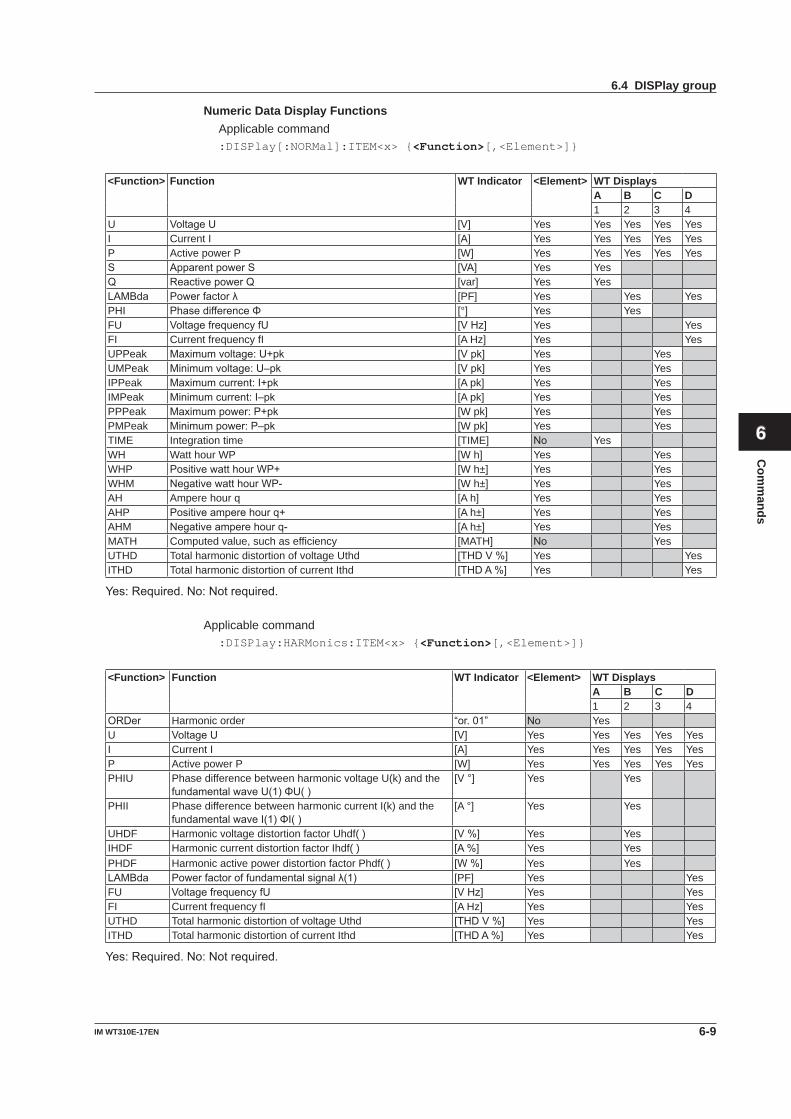
6-9IM WT310E-17EN
Com
mands
1
2
3
4
5
6
7
8
9
App
Index
Numeric Data Display Functions Applicable command
:DISPlay[:NORMal]:ITEM<x> {<Function>[,<Element>]}
<Function> Function WT Indicator <Element> WT DisplaysA B C D1 2 3 4
U VoltageU [V] Yes Yes Yes Yes YesI Current I [A] Yes Yes Yes Yes YesP Active power P [W] Yes Yes Yes Yes YesS ApparentpowerS [VA] Yes YesQ ReactivepowerQ [var] Yes YesLAMBda Powerfactorλ [PF] Yes Yes YesPHI PhasedifferenceΦ [°] Yes YesFU VoltagefrequencyfU [VHz] Yes YesFI Current frequency fI [A Hz] Yes YesUPPeak Maximumvoltage:U+pk [Vpk] Yes YesUMPeak Minimumvoltage:U–pk [Vpk] Yes YesIPPeak Maximumcurrent:I+pk [A pk] Yes YesIMPeak Minimumcurrent:I–pk [A pk] Yes YesPPPeak Maximumpower:P+pk [W pk] Yes YesPMPeak Minimumpower:P–pk [W pk] Yes YesTIME Integration time [TIME] No YesWH Watt hour WP [W h] Yes YesWHP PositivewatthourWP+ [W h±] Yes YesWHM NegativewatthourWP- [W h±] Yes YesAH Ampere hour q [A h] Yes YesAHP Positiveamperehourq+ [A h±] Yes YesAHM Negativeamperehourq- [A h±] Yes YesMATH Computed value, such as efficiency [MATH] No YesUTHD Total harmonic distortion of voltage Uthd [THDV%] Yes YesITHD Total harmonic distortion of current Ithd [THDA%] Yes Yes
Yes:Required.No:Notrequired.
Applicable command:DISPlay:HARMonics:ITEM<x> {<Function>[,<Element>]}
<Function> Function WT Indicator <Element> WT DisplaysA B C D1 2 3 4
ORDer Harmonic order “or.01” No YesU VoltageU [V] Yes Yes Yes Yes YesI Current I [A] Yes Yes Yes Yes YesP Active power P [W] Yes Yes Yes Yes YesPHIU Phase difference between harmonic voltage U(k) and the
fundamentalwaveU(1)ΦU()[V°] Yes Yes
PHII Phase difference between harmonic current I(k) and the fundamentalwaveI(1)ΦI()
[A °] Yes Yes
UHDF Harmonic voltage distortion factor Uhdf( ) [V%] Yes YesIHDF Harmonic current distortion factor Ihdf( ) [A%] Yes YesPHDF Harmonic active power distortion factor Phdf( ) [W%] Yes YesLAMBda Powerfactoroffundamentalsignalλ(1) [PF] Yes YesFU VoltagefrequencyfU [VHz] Yes YesFI Current frequency fI [A Hz] Yes YesUTHD Total harmonic distortion of voltage Uthd [THDV%] Yes YesITHD Total harmonic distortion of current Ithd [THDA%] Yes Yes
Yes:Required.No:Notrequired.
6.4 DISPlay group
6-10 IM WT310E-17EN
:HARMonics?Function Queriesallharmonicmeasurementsettings.Syntax :HARMonics?
:HARMonics:PLLSourceFunction SetsorqueriesthePLL source.Syntax :HARMonics:PLLSource {U<x>|I<x>}
:HARMonics:PLLSource?
<x> = 1 to 3 (element)Example :HARMONICS:PLLSOURCE U1
:HARMONICS:PLLSOURCE?
-> :HARMONICS:PLLSOURCE U1
:HARMonics:ORDerFunction Setsorqueriesthemaximumandminimum
harmonic orders that are analyzed.Syntax :HARMonics:ORDer {<NRf>,<NRf>}
:HARMonics:ORDer?
First <NRf> = 1 (minimum harmonic order that is analyzed, fixed at 1) Second<NRf> = 1 to 50 (maximum harmonic order that is analyzed)
Example :HARMONICS:ORDER 1,50
:HARMONICS:ORDER?
-> :HARMONICS1:ORDER 1,50
:HARMonics:THDFunction Setsorqueriestheequationusedtocomputethe
THD (total harmonic distortion).Syntax :HARMonics:THD {TOTal|FUNDamental}
:HARMonics:THD?
Example :HARMONICS:THD FUNDAMENTAL
:HARMONICS:THD?
-> :HARMONICS:THD FUNDAMENTAL
:HARMonics:DISPlay?Function Queriesallharmonicmeasurementdisplay
settings.Syntax :HARMonics:DISPlay?
6.5 HARMonics Group
The commands in this group deal with harmonic measurement.YoucanmakethesamesettingsandqueriesthatyoucanmakebypressingHARMONICSonthefrontpanel.Thecommandsinthisgrouparevalidonlyonmodelswiththeharmonicmeasurement(/G5)option.
:HARMonics:DISPlay[:STATe]Function Setsorqueriestheon/offstateofharmonic
measurement data display.Syntax :HARMonics:DISPlay[:STATe]
{<Boolean>}
:HARMonics:DISPlay:STATe?
Example :HARMONICS:DISPLAY:STATE ON
:HARMONICS:DISPLAY:STATE?
-> :HARMONICS:DISPLAY:STATE 1
:HARMonics:DISPlay:ORDerFunction Setsorqueriestheharmonicorderofthe
harmoniccomponentthatisshownindisplayBfor the harmonic measurement data display.
Syntax :HARMonics:DISPlay:ORDer {<NRf>}
:HARMonics:DISPlay:ORDer?
<NRf> = 1 to 50 (harmonic order)Example :HARMONICS:DISPLAY:ORDER 1
:HARMONICS:DISPLAY:ORDER?
-> :HARMONICS:DISPLAY:ORDER 1
6-11IM WT310E-17EN
Com
mands
1
2
3
4
5
6
7
8
9
App
Index
6.6 HOLD Group
The command in this group deals with the output data hold feature.You can make the same settings and queries that you can make by pressing HOLD on the front panel.
:HOLDFunction Setsorqueriestheon/offstateoftheoutputhold
feature for display, communication, and other types of data.
Syntax :HOLD {<Boolean>}
:HOLD?
Example :HOLD OFF
:HOLD? -> :HOLD 0
6-12 IM WT310E-17EN
:INPut?Function Queriesallinputsettings.Syntax :INPut?
[:INPut]:CFACtorFunction Setsorqueriesthecrest factor.Syntax [:INPut]:CFACtor {<NRf>|A6}
[:INPut]:CFACtor?
<NRf> = 3, 6 A6 = Displayrangeexpandmode(6A)forcrestfactor6
Example :INPUT:CFACTOR 3
:INPUT:CFACTOR?
-> :INPUT:CFACTOR 3
[:INPut]:WIRingFunction Setsorqueriesthewiring system.Syntax [:INPut]:WIRing {(P1W2|P1W3|P3W3|
P3W4|V3A3)}
[:INPut]:WIRing?
P1W2 = Single-phase,two-wiresystem [1P2W] P1W3 = Single-phase,three-wiresystem [1P3W]
P3W3 = Three-phase,three-wiresystem [3P3W] P3W4 = Three-phase,four-wiresystem [3P4W] V3A3 = Three-phase,three-wiresystemwithathree-voltage,three-currentmethod[3V3A]
Example :INPUT:WIRING P1W3
:INPUT:WIRING?
-> :INPUT:WIRING P1W3
Description • FortheWT310EandWT310EH,thewiringsystemisfixedtoP1W2.Noothersettingisallowed.
• FortheWT332EandWT333E,thewiringsystem cannot be set to P1W2.
[:INPut]:MODEFunction Setsorqueriesthevoltageandcurrent
measurement mode.Syntax [:INPut]:MODE {RMS|VMEan|DC}
[:INPut]:MODE?
Example :INPUT:MODE RMS
:INPUT:MODE? -> :INPUT:MODE RMS
[:INPut]:VOLTage?Function Queriesallvoltagemeasurementsettings.Syntax [:INPut]:VOLTage?
6.7 INPut Group
The commands in this group deal with the measurement conditions of the input elements.YoucanmakethesamesettingsandqueriesthatyoucanbypressingtheWIRING,MODE,VOLTAGE,CURRENT,orUTILITYkeyonthefrontpanelandthenusingtheCForrAnGEmenuorbypressingtheSETUPkeyandthenusingtheSCALE,rAtio,SYnC,L.FiLt,orF.FiLtmenu.
[:INPut]:VOLTage:RANGeFunction Setsorqueriesthevoltage range.Syntax [:INPut]:VOLTage:RANGe {<Voltage>}
[:INPut]:VOLTage:RANGe?
• Whenthecrestfactorissetto3 <Voltage>=15,30,60,150,300,600(V) • Whenthecrestfactorissetto6or6A <Voltage>=7.5,15,30,75,150,300(V)Example :INPUT:VOLTAGE:RANGE 600V
:INPUT:VOLTAGE:RANGE?
-> :INPUT:VOLTAGE:RANGE 600.0E+00
[:INPut]:VOLTage:AUTOFunction Setsorqueriesthevoltageauto range on/off
state.Syntax [:INPut]:VOLTage:AUTO {<Boolean>}
[:INPut]:VOLTage:AUTO?
Example :INPUT:VOLTAGE:AUTO ON
:INPUT:VOLTAGE:AUTO?
-> :INPUT:VOLTAGE:AUTO 1
[:INPut]:VOLTage:CONFigFunction Setsorqueriesthevalidvoltagerange.Syntax [:INPut]:VOLTage:CONFig
{ALL|<Voltage>[,<Voltage>] [,<Voltage>]...} [:INPut]:VOLTage:CONFig?
ALL = All ranges are valid. <Voltage> = See(:INPut:VOLTage:RANGe).
Example :INPUT:VOLTAGE:CONFIG ALL
:INPUT:VOLTAGE:CONFIG?
-> :INPUT:VOLTAGE:CONFIG ALL
:INPUT:VOLTAGE:CONFIG 600,150,15
:INPUT:VOLTAGE:CONFIG?
-> :INPUT:VOLTAGE:CONFIG 600.0E+00,
150.0E+00,15.0E+00
Description In the parameters, list the voltage ranges that you want to enable. To enable all the ranges, specify theparameter“ALL.”
6-13IM WT310E-17EN
Com
mands
1
2
3
4
5
6
7
8
9
App
Index
[:INPut]:VOLTage:POJumpFunction Setsorqueriesthejumpdestinationrangethatis
usedwhenavoltagepeakover-rangeoccurs.Syntax [:INPut]:VOLTage:POJump
{OFF|<Voltage>} [:INPut]:VOLTage:POJump?
OFF=Nojumpdestinationvoltagerange <Voltage> = See(:INPut:VOLTage:RANGe).
Example :INPUT:VOLTAGE:POJUMP 600V
:INPUT:VOLTAGE:POJUMP?
-> :INPUT:VOLTAGE:POJUMP 600.0E+00
[:INPut]:CURRent?Function Queriesallelectriccurrentmeasurementsettings.Syntax [:INPut]:CURRent?
[:INPut]:CURRent:RANGeFunction Setsorqueriesthecurrent range.Syntax [:INPut]:CURRent:RANGe
{<Current>|(EXTernal,<Voltage>)} [:INPut]:CURRent:RANGe?
• Fordirectcurrentinput • Whenthecrestfactorissetto3 <Current>=5,10,20,50,100,200,500(mA),
1,2,5,10,20(A)(WT310E) <Current>=1,2,5,10,20,40(A)(WT310EH) <Current>=0.5,1,2,5,10,20(A)(WT332E,WT333E)
• Whenthecrestfactorissetto6or6A <Current>=2.5,5,10,25,50,100,250(mA),
0.5,1,2.5,5,10(A)(WT310E) <Current>=0.5,1,2.5,5,10,20(A)(WT310EH) <Current>=0.25,0.5,1,2.5,5,10(A)(WT332E,WT333E)
• Forexternalcurrentsensorinput • Whenthecrestfactorissetto3 <Voltage>=2.5,5,10(V)(/EX1)
<Voltage>=50,100,200,500(mV),1,2(V)(/EX2)
• Whenthecrestfactorissetto6or6A <Voltage>=1.25,2.5,5(V)(/EX1)
<Voltage>=25,50,100,250(mV),0.5,1(V)(/EX2)
Example :INPUT:CURRENT:RANGE 20A
:INPUT:CURRENT:RANGE?
-> :INPUT:CURRENT:RANGE 20.0E+00
:INPUT:CURRENT:RANGE EXTERNAL,10V
:INPUT:CURRENT:RANGE?
-> :INPUT:CURRENT:RANGE
EXTERNAL,10.0E+00
Description EXTernaland<Voltage>canonlybeselectedon models with the external current sensor input (/EX1 or /EX2) option.
[:INPut]:CURRent:AUTOFunction Setsorqueriesthecurrentauto range on/off state.Syntax [:INPut]:CURRent:AUTO {<Boolean>}
[:INPut]:CURRent:AUTO?
Example :INPUT:CURRENT:AUTO ON
:INPUT:CURRENT:AUTO?
-> :INPUT:CURRENT:AUTO 1
[:INPut]:CURRent:CONFigFunction Setsorqueriesthevalidcurrentrange.Syntax [:INPut]:CURRent:CONFig {ALL|<Current>
[,<Current>][,<Current>]...} [:INPut]:CURRent:CONFig?
ALL = All ranges are valid. <Current> = See(:INPut:CURRent:RANGe).
Example :INPUT:CURRENT:CONFIG ALL
:INPUT:CURRENT:CONFIG?
-> :INPUT:CURRENT:CONFIG ALL
:INPUT:CURRENT:CONFIG 20,5,1
:INPUT:CURRENT:CONFIG?
-> :INPUT:CURRENT:CONFIG
20.0E+00,5.0E+00,1.0E+00
Description In the parameters, list the current ranges that you want to enable. To enable all the ranges, specify theparameter“ALL.”
[:INPut]:CURRent:POJumpFunction Setsorqueriesthejumpdestinationrangethatis
usedwhenacurrentpeakover-rangeoccurs.Syntax [:INPut]:CURRent:POJump
{OFF|<Current>} [:INPut]:CURRent:POJump?
OFF=Nojumpdestinationcurrentrange <Current> = See(:INPut:CURRent:RANGe).
Example :INPUT:CURRENT:POJUMP 20A
:INPUT:CURRENT:POJUMP?
-> :INPUT:CURRENT:POJUMP 20.0E+00
[:INPut]:CURRent:EXTSensor:CONFigFunction Setsorqueriesthevalidexternalcurrent sensor
range.Syntax [:INPut]:CURRent:EXTSensor:CONFig
{ALL|<Voltage>[,<Voltage>] [,<Voltage>]...} [:INPut]:CURRent:EXTSensor:CONFig?
ALL = All ranges are valid. <Voltage> = See(:INPut:CURRent:RANGe).
Example :INPUT:CURRENT:EXTSENSOR:CONFIG ALL
:INPUT:CURRENT:EXTSENSOR:CONFIG? ->
:INPUT:CURRENT:EXTSENSOR:CONFIG ALL
:INPUT:CURRENT:EXTSENSOR:CONFIG
2,0.5,0.1
:INPUT:CURRENT:EXTSENSOR:CONFIG?
-> :INPUT:CURRENT:EXTSENSOR:CONFIG
2.00E+00,500.0E-03,100.0E-03
6.7 INPut Group
6-14 IM WT310E-17EN
Description In the parameters, list the external current sensor ranges that you want to enable. To enable all the ranges,specifytheparameter“ALL.”
[:INPut]:CURRent:EXTSensor:POJumpFunction Setsorqueriesthejumpdestinationrangethatis
usedwhenacurrentpeakover-rangeoccurs.Syntax [:INPut]:CURRent:EXTSensor:POJump
{OFF|<Voltage>} [:INPut]:CURRent:EXTSensor:POJump?
OFF=Nojumpdestinationcurrentrange <Voltage> = See(:INPut:CURRent:RANGe).
Example :INPUT:CURRENT:EXTSENSOR:POJUMP 2V
:INPUT:CURRENT:EXTSENSOR:POJUMP?
-> :INPUT:CURRENT:EXTSENSOR:POJUMP
2.00E+00
[:INPut]:CURRent:SRATio?Function Queriestheexternalcurrent sensor conversion
ratios of all elements.Syntax [:INPut]:CURRent:SRATio?
Description This command is only valid on models with the external current sensor input (/EX1 or /EX2) option.
[:INPut]:CURRent:SRATio[:ALL]Function Collectively sets the external current sensor
conversion ratios of all elements.Syntax [:INPut]:CURRent:SRATio[:ALL]
{<NRf>}
<NRf> = 0.001 to 9999.Example :INPUT:CURRENT:SRATIO:ALL 10
[:INPut]:CURRent:SRATio:ELEMent<x>Function Setsorqueriestheexternalcurrentsensor
conversion ratio of the specified element.Syntax [:INPut]:CURRent:SRATio:ELEMent<x>
{<NRf>}
[:INPut]:CURRent:SRATio:ELEMent<x>?
<x> = 1 to 3 (element) <NRf> = 0.001 to 9999.
Example :INPUT:CURRENT:SRATIO:ELEMENT1 10
:INPUT:CURRENT:SRATIO:ELEMENT1?
-> :INPUT:CURRENT:SRATIO:ELEMENT1
10.00
[:INPut]:RCONfigFunction Setsorqueriestheon/offstateoftherange
configuration (valid range selection) feature.Syntax [:INPut]:RCONfig {<Boolean>}
[:INPut]:RCONfig?
Example :INPUT:RCONFIG OFF
:INPUT:RCONFIG? -> :INPUT:RCONFIG 0
Description The following commands are enabled only when thiscommandissettoON.Measurementrangecan be skipped. :INPut:VOLTage:CONFig
:INPut:VOLTage:POJump
:INPut:CURRent:CONFig
:INPut:CURRent:POJump
:INPut:CURRent:EXTSensor:CONFig
:INPut:CURRent:EXTSensor:POJump
[:INPut]:SCALing?Function Queriesallscaling settings.Syntax [:INPut]:SCALing?
[:INPut]:SCALing[:STATe]Function Setsorqueriesthescalingon/offstate.Syntax [:INPut]:SCALing[:STATe] {<Boolean>}
[:INPut]:SCALing:STATe?
Example :INPUT:SCALING:STATE OFF
:INPUT:SCALING:STATE?
-> :INPUT:SCALING:STATE 0
[:INPut]:SCALing:{VT|CT|SFACtor}?Function QueriestheVTratios,CT ratios, or power
coefficients of all elements.Syntax [:INPut]:SCALing:{VT|CT|SFACtor}?
[:INPut]:SCALing:{VT|CT|SFACtor}[:ALL]Function CollectivelysetstheVTratio,CTratio,orpower
coefficient of all elements.Syntax [:INPut]:SCALing:{VT|CT|SFACtor}
[:ALL] {<NRf>}
<NRf> = 0.001 to 9999.Example :INPUT:SCALING:VT:ALL 1
[:INPut]:SCALing:{VT|CT|SFACtor}:ELEMent<x>Function SetsorqueriestheVTratio,CTratio,orpower
coefficient of the specified element.Syntax [:INPut]:SCALing:{VT|CT|SFACtor}
:ELEMent<x> {<NRf>}
[:INPut]:SCALing:{VT|CT|SFACtor}
:ELEMent<x>?
<x> = 1 to 3 (element) <NRf> = 0.001 to 9999.
Example :INPUT:SCALING:VT:ELEMENT1 1
:INPUT:SCALING:VT:ELEMENT1?
-> :INPUT:SCALING:VT:ELEMENT1 1.000
[:INPut]:SYNChronizeFunction Setsorqueriesthesynchronization source.Syntax [:INPut]:SYNChronize
{VOLTage|CURRent|OFF}
[:INPut]:SYNChronize?
Example :INPUT:SYNCHRONIZE VOLTAGE
:INPUT:SYNCHRONIZE?
-> :INPUT:SYNCHRONIZE VOLTAGE
6.7 INPut Group
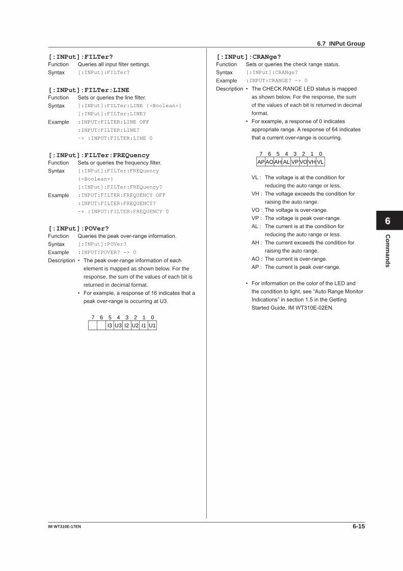
6-15IM WT310E-17EN
Com
mands
1
2
3
4
5
6
7
8
9
App
Index
[:INPut]:FILTer?Function Queriesallinput filter settings.Syntax [:INPut]:FILTer?
[:INPut]:FILTer:LINEFunction Setsorqueriestheline filter.Syntax [:INPut]:FILTer:LINE {<Boolean>}
[:INPut]:FILTer:LINE?
Example :INPUT:FILTER:LINE OFF
:INPUT:FILTER:LINE?
-> :INPUT:FILTER:LINE 0
[:INPut]:FILTer:FREQuencyFunction Setsorqueriesthefrequency filter.Syntax [:INPut]:FILTer:FREQuency
{<Boolean>}
[:INPut]:FILTer:FREQuency?
Example :INPUT:FILTER:FREQUENCY OFF
:INPUT:FILTER:FREQUENCY?
-> :INPUT:FILTER:FREQUENCY 0
[:INPut]:POVer?Function Queriesthepeakover-rangeinformation.Syntax [:INPut]:POVer?
Example :INPUT:POVER? -> 0
Description • Thepeakover-rangeinformationofeachelement is mapped as shown below. For the response, the sum of the values of each bit is returned in decimal format.
• Forexample,aresponseof16indicatesthatapeakover-rangeisoccurringatU3.
U1I2 U2 I1U3I37 6 5 4 3 2 1 0
[:INPut]:CRANge?Function Setsorqueriesthecheck range status.Syntax [:INPut]:CRANge?
Example :INPUT:CRANGE? -> 0
Description • TheCHECKRANGELEDstatusismappedas shown below. For the response, the sum of the values of each bit is returned in decimal format.
• Forexample,aresponseof0indicatesappropriaterange.Aresponseof64indicatesthatacurrentover-rangeisoccurring.
VLVO VHVPALAHAOAP7 6 5 4 3 2 1 0
VL: Thevoltageisattheconditionforreducing the auto range or less.
VH: Thevoltageexceedstheconditionforraising the auto range.
VO: Thevoltageisover-range. VP: Thevoltageispeakover-range. AL: Thecurrentisattheconditionfor
reducing the auto range or less. AH: Thecurrentexceedstheconditionfor
raising the auto range. AO: Thecurrentisover-range. AP: Thecurrentispeakover-range.
• ForinformationonthecoloroftheLEDandtheconditiontolight,see“AutoRangeMonitorIndications”insection1.5intheGettingStartedGuide,IMWT310E-02EN.
6.7 INPut Group
6-16 IM WT310E-17EN
6.8 INTEGrate Group
The commands in this group deal with integration.YoucanmakethesamesettingsandqueriesthatyoucanmakebypressingINTEGSET,START,STOP,andRESETon the front panel.
:INTEGrate:STATe?Function Queriestheintegrationstatus.Syntax :INTEGrate:STATe?
Example :INTEGRATE:STATE? -> RESET
Description • Theresponseisasfollows: RESet=Integrationreset STARt=Integrationinprogress STOP=Integrationstop ERRor=Abnormalintegrationtermination
(integration overflow, power failure) TIMeup = Integration stop due to integration
timeout
:INTEGrate?Function Queriesallintegration settings.Syntax :INTEGrate?
:INTEGrate:MODEFunction Setsorqueriestheintegration mode.Syntax :INTEGrate:MODE {NORMal|CONTinuous}
:INTEGrate:MODE?
NORMal=Standardintegrationmode CONTinuous = Continuous integration mode
Example :INTEGRATE:MODE NORMAL
:INTEGRATE:MODE?
-> :INTEGRATE:MODE NORMAL
:INTEGrate:TIMerFunction Setsorqueriestheintegration timer value.Syntax :INTEGrate:TIMer {<NRf>,<NRf>,<NRf>}
:INTEGrate:TIMer?
{<NRf>,<NRf>,<NRf>} = 0,0,0 to 10000,0,0
First <NRf> = 0 to 10000 (hours) Second<NRf> = 0 to 59 (minutes) Third <NRf> = 0 to 59 (seconds)
Example :INTEGRATE:TIMER 1,0,0
:INTEGRATE:TIMER?
-> :INTEGRATE:TIMER 1,0,0
:INTEGrate:STARtFunction Startsintegration.Syntax :INTEGrate:STARt
Example :INTEGRATE:START
:INTEGrate:STOPFunction Stopsintegration.Syntax :INTEGrate:STOP
Example :INTEGRATE:STOP
:INTEGrate:RESetFunction Resetstheintegratedvalue.Syntax :INTEGrate:RESet
Example :INTEGRATE:RESET
6-17IM WT310E-17EN
Com
mands
1
2
3
4
5
6
7
8
9
App
Index
6.9 MATH Group
The commands in this group deal with computations. You can make the same settings and queries that you can by pressingSETUPonthefrontpanelandusingtheMAtHmenu.
:MATHFunction SetsorqueriestheMATHequation.Syntax :MATH {EFFiciency|CFU<x>|CFI<x>|ADD|
SUB|MUL|DIV|DIVA|DIVB|AVW<x>}
:MATH?
<x> of {CFU|CFI} = 1 to 3 (element) <x> of {AVW} = 1 to 3 (element), 4 (Σ)
Example :MATH CFU1
:MATH? -> :MATH CFU1
Description The equations that correspond to each option are asfollows: EFFiciency:Efficiency(validonlyonthe WT332E/WT333E) CFU:Voltagecrestfactor CFI:Currentcrestfactor ADD:A+B SUB:A-B MUL:A×B DIV:A/B DIVA:A/B^2 DIVB:A^2/B AVW:Averageactivepowerduringintegration
6-18 IM WT310E-17EN
:MEASure?Function Queriesallmeasuredandcomputeddataoutput
settings.Syntax :MEASure?
:MEASure:AVERaging?Function Queriesallaveraging settings.Syntax :MEASure:AVERaging?
:MEASure:AVERaging[:STATe]Function Setsorqueriestheon/offstateofaveraging.Syntax :MEASure:AVERaging[:STATe]
{<Boolean>}
:MEASure:AVERaging:STATe?
Example :MEASURE:AVERAGING:STATE ON
:MEASURE:AVERAGING:STATE?
-> :MEASURE:AVERAGING:STATE 1
:MEASure:AVERaging:TYPEFunction Setsorqueriestheaveragingtype.Syntax :MEASure:AVERaging:TYPE
{LINear|EXPonent}
:MEASure:AVERaging:TYPE?
Example :MEASURE:AVERAGING:TYPE LINEAR
:MEASURE:AVERAGING:TYPE?
-> :MEASURE:AVERAGING:TYPE LINEAR
Description The averaging of harmonic measurement functions (option) is only valid when the type is set to EXPonent. For details, see the User’s Manual,IMWT310E-01EN.
:MEASure:AVERaging:COUNtFunction Setsorqueriestheaveragingcoefficient.Syntax :MEASure:AVERaging:COUNt {<NRf>}
:MEASure:AVERaging:COUNt?
<NRf> = 8, 16, 32, 64 (moving average count or attenuation constant)
Example :MEASURE:AVERAGING:COUNT 8
:MEASURE:AVERAGING:COUNT?
-> :MEASURE:AVERAGING:COUNT 8
Description The averaging of harmonic measurement functions (option) is only valid when TYPE is set to EXPonent (attenuation constant). For details, seetheUser’sManual,IMWT310E-01EN.
6.10 MEASure Group
The commands in this group deal with computation.YoucanmakethesamesettingsandqueriesthatyoucanbypressingSETUPonthefrontpanelandusingtheAVGmenu or by pressing MAX HOLD on the front panel.
:MEASure:MHOLdFunction SetstheMAX hold on/off state.Syntax :MEASure:MHOLd {<Boolean>}
:MEASure:MHOLd?
Example :MEASURE:MHOLD ON
:MEASURE:MHOLD? -> :MEASURE:MHOLD 1
6-19IM WT310E-17EN
Com
mands
1
2
3
4
5
6
7
8
9
App
Index
:NUMeric?Function Queriesallnumericdataoutputsettings.Syntax :NUMeric?
:NUMeric:FORMatFunction Setsorqueriesthenumericdataformat.Syntax :NUMeric:FORMat {ASCii|FLOat}
:NUMeric:FORMat?
Example :NUMERIC:FORMAT ASCII
:NUMERIC:FORMAT?
-> :NUMERIC:FORMAT ASCII
Description • Theformatofthenumericdatathatisoutputvaries depending on how this command is set. The different formats are explained below.
(1)ASCii Physicalvaluesareoutputinthe<NR3>format.(Only the elapsed integration time—TIME—isoutputin<NR1>format.) The data items are separated by commas.
(2) FLOat Aheader(forexample,“#240”or“#3208”)isadded in front of each numeric data block. AphysicalvalueinIEEEsingle-precisionfloatingpoint(4-byte)formatfollowstheheader. ThebyteorderofthedataofeachitemisMSBFirst.
• Fortheformatsofeachindividualnumericdataitem,see“NumericDataFormats”attheendofthisgroupofcommands(page6-25).
:NUMeric:NORMal?Function Queriesallnumericdataoutputsettings.Syntax :NUMeric:NORMal?
Description Thenumberofnumericdataitemsoutputby:NUMeric[:NORMal]:ITEM<x>isdeterminedby:NUMeric[:NORMal]NUMber.
:NUMeric[:NORMal]:VALue?Function Queriesthenumericdata.Syntax :NUMeric[:NORMal]:VALue? {<NRf>}
<NRf> = 1 to 255 (item number)Example • When<NRf> is specified
:NUMERIC:NORMAL:VALUE? 1
-> 103.79E+00
• When<NRf> is omitted :NUMERIC:NORMAL:VALUE?
-> 103.79E+00,1.0143E+00,105.27E+0
0,..(omitted)..,50.001E+00 • When:NUMeric:FORMat is set to {FLOat}
:NUMERIC:NORMAL:VALUE?
-> #N (N-digitbytenumber)(databytesequence)
Description • If<NRf>isspecified,onlythenumericdataforthe specified item is output.
• If<NRf>isomitted,thenumericdataitemsfrom1tothenumberspecifiedbythe:NUMeric[:NORMal]:NUMbercommandareoutput in order.
• Fortheformatsofeachindividualnumericdataoutputitem,see“NumericDataFormats”attheendofthisgroupofcommands(page6-25).
:NUMeric[:NORMal]:NUMberFunction Setsorqueriesthenumberofnumericdataitems
thataretransmittedbythe:NUMeric[:NORMal]:VALue?command.
Syntax :NUMeric[:NORMal]:NUMber {<NRf>|ALL}
:NUMeric[:NORMal]:NUMber?
<NRf> = 1 to 255(ALL)Example :NUMERIC:NORMAL:NUMBER 10
:NUMERIC:NORMAL:NUMBER
-> :NUMERIC:NORMAL:NUMBER 10
Description • Iftheparameterisomittedfromthe:NUMeric[:NORMal]:VALue?command,thenumericdataitems from 1 to the specified value are output in order.
• Bydefault,thenumberofnumericdataitemsisset to 10.
6.11 NUMeric Group
The command in this group deal with numeric data output.There are no front panel keys that correspond to the commands in this group.The commands in theDISPlaygroupareused tomake the samesettingsandqueriesas theFUNCTIONandELEMENTkeysonthefrontpanel.
6-20 IM WT310E-17EN
:NUMeric[:NORMal]:ITEM<x>Function Setsorqueriesthespecifiednumericdataoutput
item (function, element, and harmonic order).Syntax :NUMeric[:NORMal]:ITEM<x> {NONE|
<Function>[,<Element>][,<Order>]}
:NUMeric[:NORMal]:ITEM<x>?
<x> = 1 to 255 (item number) NONE=Nooutputitem <Function> = {U|I|P|S|Q|...} <Element> = {<NRf>|SIGMa} (<NRf> = 1 to 3) <Order> = {TOTal|DC|<NRf>} (<NRf> = 1 to 50)
Example :NUMERIC:NORMAL:ITEM1 U,1
:NUMERIC:NORMAL:ITEM1?
-> :NUMERIC:NORMAL:ITEM1 U,1
:NUMERIC:NORMAL:ITEM1 UK,1,1
:NUMERIC:NORMAL:ITEM1?
-> :NUMERIC:NORMAL:ITEM1 UK,1,1
Description • Fordetailson<Function>options,see“FunctionOptionList(1)”attheendofthisgroupofcommands(page6-24).
• If<Element>isomitted,theelementissetto1. • If<Order>isomitted,theorderissettoTOTal. • <Element>and<Order>areomittedfrom
responses to functions that do not need them. • Thisinstrumentdoesnotmeasuredatafor
<Order> = DC.
:NUMeric[:NORMal]:PRESetFunction Presets the numeric data output item pattern.Syntax :NUMeric[:NORMal]:PRESet {<NRf>}
<NRf> = 1 to 4Example :NUMERIC:NORMAL:PRESET 1
Description • Forinformationabouttheoutputitemsthatarepreset,see“(1)PresetPatternsforNumericDataItems”onpage6-26attheendofthecommands for this group.
• Bydefault,theoutputitemsofPattern2areselected.
:NUMeric[:NORMal]:CLEarFunction Clears numeric data output items (sets the items
toNONE).Syntax :NUMeric[:NORMal]:CLEar
{ALL|<NRf>[,<NRf>]}
ALL = Clear all items First <NRf> = 1 to 255 (the number of the first item to clear) Second<NRf> = 1 to 255 (the number of the last item to clear)
Example :NUMERIC:NORMAL:CLEAR ALL
Description Ifthe2nd<NRf>isomitted,theoutputitemspecified by the first and all following output items (uptonumber255)arecleared.
:NUMeric[:NORMal]:DELeteFunction Deletes numeric data output items.Syntax :NUMeric[:NORMal]:DELete
{<NRf>[,<NRf>]}
1st <NRf> = 1 to 255 (the number of the first item to delete) Second<NRf> = 1 to 255 (the number of the last item to delete)
Example :NUMERIC:NORMAL:DELETE 1 (Deletes ITEM1 and shifts ITEM2 and subsequent items forward) :NUMERIC:NORMAL:DELETE 1,3 (Deletes ITEM1 to ITEM3 and shifts ITEM4 and subsequent items forward)
Description • Whenoutputitemsaredeleted,subsequentitems shift forward to fill the empty positions. EmptypositionsattheendaresettoNONE.
• Ifthesecond<NRf>isomitted,onlytheoutputitem specified by the first number is deleted.
:NUMeric[:NORMal]:HEADer?Function Queriesthenumericdataheader.Syntax :NUMeric[:NORMal]:HEADer? {<NRf>}
<NRf> = 1 to 255 (item number)Example • When<NRf> is specified :NUMERIC:NORMAL:HEADER? 1
-> U-E1
• When<NRf> is omitted (when :NUMeric[:NORMal]:NUMber is set to 3) :NUMERIC:NORMAL:HEADER?
-> U-E1,I-E1,P-E1
Description • Thedataname(header)oftheoutputitemisgenerated.
• If<NRf>isspecified,onlythedatanameforthe specified item number is output.
• If<NRf>isomitted,thedatanamesoftheitems from 1 to the number specified by the :NUMeric[:NORMal]:NUMbercommandareoutput in order.
6.11 NUMeric Group
6-21IM WT310E-17EN
Com
mands
1
2
3
4
5
6
7
8
9
App
Index
:NUMeric:LIST?Function Queriesallharmonicmeasurementnumericlist
data output settings.Syntax :NUMeric:LIST?
Description • Thisisonlyvalidonmodelswiththeharmonicmeasurement(/G5)option.
• Thenumberofnumericlistdataitemsoutputby:NUMeric:LIST:ITEM<x>isdeterminedby:NUMeric:LIST:NUMber.
:NUMeric:LIST:VALue?Function Queriestheharmonicmeasurementnumericlist
data.Syntax :NUMeric:LIST:VALue? {<NRf>}
<NRf> = 1 to 32 (item number)Example • When<NRf>isspecified
:NUMERIC:LIST:VALUE? 1
-> 103.58E+00,NAN,103.53E+00
,0.09E+00,2.07E+00,0.04E+00,..
(omitted)..,0.01E+00,0.01E+00 (upto52datavalues)
• When<NRf> is omitted (when :NUMeric :LIST:NUMberissetto5) :NUMERIC:LIST:VALUE?
-> 103.58E+00,NAN,103.53E+00
,0.09E+00,2.07E+00,0.04E+00,..
(omitted)..,0.00E+00,0.00E+00 (upto52*5=260datavalues)
• When:NUMeric:FORMat is set to {FLOat} :NUMERIC:LIST:VALUE?
-> #N(N-digitbytenumber)(databytesequence)
Description • Thisisonlyvalidonmodelswiththeharmonicmeasurement(/G5)option.
• Asinglenumericlistdataitemconsistsofupto52itemsofnumericdatainthefollowingorder:TOTal,DC,1stharmonic,...,:NUMeric:LIST:ORDer.
• If<NRf>isspecified,onlythenumericlistdataofthespecifieditemnumberisoutput(upto52items of data).
• If<NRf>isomitted,thenumericlistdataofitemnumbersfrom1to:NUMeric:LIST:NUMberisoutputinorder(upto52timesthenumberspecifiedby:NUMeric:LIST:NUMber).
• Fortheformatsofeachindividualnumericdataoutputitem,see“NumericDataFormats”attheendofthisgroupofcommands(page6-25).
• ThisinstrumentdoesnotmeasuredatafortheDCcomponent.Itisalways“NAN.”
:NUMeric:LIST:NUMberFunction Setsorqueriesthenumberofnumeric
list data items that are transmitted by :NUMeric:LIST:VALue?.
Syntax :NUMeric:LIST:NUMber {<NRf>|ALL}
:NUMeric:LIST:NUMber?
<NRf> = 1 to 32(ALL)Example :NUMERIC:LIST:NUMBER 5
:NUMERIC:LIST:NUMBER
-> :NUMERIC:LIST:NUMBER 5
Description • Thisisonlyvalidonmodelswiththeharmonicmeasurement(/G5)option.
• Iftheparameterisomittedfromthe:NUMeric:LIST:VALue?command,thenumericlist data items from 1 to the specified value are output in order.
• Bydefault,thenumberofnumericlistdataitems is set to 1.
:NUMeric:LIST:ORDerFunction Setsorqueriesthemaximumoutputharmonic
order of the harmonic measurement numeric list data.
Syntax :NUMeric:LIST:ORDer {<NRf>|ALL}
:NUMeric:LIST:ORDer?
<NRf> = 1 to 50(ALL)Example :NUMERIC:LIST:ORDER 50
:NUMERIC:LIST:ORDER?
-> :NUMERIC:LIST:ORDER 50
Description This is only valid on models with the harmonic measurement(/G5)option.
:NUMeric:LIST:SELectFunction Setsorqueriestheoutputcomponentsofthe
harmonic measurement numeric list data.Syntax :NUMeric:LIST:SELect {EVEN|ODD|ALL}
:NUMeric:LIST:SELect?
Example :NUMERIC:LIST:SELECT ALL
:NUMERIC:LIST:SELECT?
-> :NUMERIC:LIST:SELECT ALL
Description • Thisisonlyvalidonmodelswiththeharmonicmeasurement(/G5)option.
• Theavailableoptionsareexplainedbelow. EVEN=OutputsthecomponentsofTOTal,DC,andeven-orderharmonics ODD = Outputs the components of TOTal, DC, andodd-orderharmonics ALL = Outputs all components
6.11 NUMeric Group
6-22 IM WT310E-17EN
:NUMeric:LIST:ITEM<x>Function Setsorqueriestheoutputitem(functionand
element) of the specified harmonic measurement numeric list data item.
Syntax :NUMeric:LIST:ITEM<x> {NONE|
<Function>,<Element>}
:NUMeric:LIST:ITEM<x>?
<x> = 1 to 32 (item number) NONE=Nooutputitem <Function> = {U|I|P|PHIU|PHII|UHDF| IHDF|PHDF}
<Element> = {<NRf>}(<NRf> = 1 to 3)Example :NUMERIC:LIST:ITEM1 U,1
:NUMERIC:LIST:ITEM1?
-> :NUMERIC:LIST:ITEM1 U,1
Description • Thisisonlyvalidonmodelswiththeharmonicmeasurement(/G5)option.
• Fordetailson<Function>options,see“FunctionOptionList(2)”attheendofthisgroupofcommands(page6-24).
:NUMeric:LIST:PRESetFunction Presets the harmonic measurement numeric list
data output item pattern.Syntax :NUMeric:LIST:PRESet {<NRf>}
<NRf> = 1 to 4Example :NUMERIC:LIST:PRESET 1
Description • Thisisonlyvalidonmodelswiththeharmonicmeasurement(/G5)option.
• Forinformationabouttheoutputitemsthatarepreset, see “(2) Preset Patterns for Harmonic MeasurementNumericListDataOutputItems”onpage6-28attheendofthecommandsforthis group.
• Bydefault,theoutputitemsofPattern2areselected.
:NUMeric:LIST:CLEarFunction Clears harmonic measurement numeric list data
outputitems(setstheitemstoNONE).Syntax :NUMeric:LIST:CLEar
{ALL|<NRf>[,<NRf>]}
ALL = Clear all items First <NRf> = 1 to 32 (the number of the first item to clear) Second<NRf> = 1 to 32 (the number of the last item to clear)
Example :NUMERIC:LIST:CLEAR ALL
Description • Thisisonlyvalidonmodelswiththeharmonicmeasurement(/G5)option.
• Ifthe2nd<NRf>isomitted,theoutputitemspecified by the first number and all following output items (up to number 32) are cleared.
:NUMeric:LIST:DELeteFunction Deletes harmonic measurement numeric list data
output items.Syntax :NUMeric:LIST:DELete {<NRf>[,<NRf>]}
1st <NRf> = 1 to 32 (the number of the first item to delete) Second<NRf> = 1 to 32 (the number of the last item to delete)
Example :NUMERIC:LIST:DELETE 1 (Deletes ITEM1 and shifts ITEM2 and subsequent items forward) :NUMERIC:LIST:DELETE 1,3 (Deletes ITEM1 to ITEM3 and shifts ITEM4 and subsequent items forward)
Description • Thisisonlyvalidonmodelswiththeharmonicmeasurement(/G5)option.
• Whenoutputitemsaredeleted,subsequentitems shift forward to fill the empty positions. EmptypositionsattheendaresettoNONE.
• Ifthesecond<NRf>isomitted,onlytheoutputitem specified by the first number is deleted.
6.11 NUMeric Group
6-23IM WT310E-17EN
Com
mands
1
2
3
4
5
6
7
8
9
App
Index
:NUMeric:HOLDFunction Setsorqueriestheon/off(hold/release)statusof
the numeric data hold feature.Syntax :NUMeric:HOLD {<Boolean>}
:NUMeric:HOLD?
Example :NUMERIC:HOLD ON
:NUMERIC:HOLD? -> :NUMERIC:HOLD 1
Description • If:NUMeric:HOLDissettoONbefore :NUMeric[:NORMal]:VALue?or:NUMeric:LIST:VALue?isexecuted,allthenumeric data at that point in time can be held internally.
• Aslongas:NUMeric:HOLDissettoON,numeric data is held even when the numeric data on the screen is updated.
• Forexample,ifyouwishtoretrievevarioustypes of numeric data from each element at the same point in time, use the following commands: :NUMeric:HOLDON :NUMeric[:NORMal]:ITEM1U,1;ITEM2I,1;...(Setthenumericdataitemsofelement1.) :NUMeric[:NORMal]:VALue? (Receivethenumericdataofelement1.) :NUMeric[:NORMal]:ITEM1U,2;ITEM2I,2;...(Setthenumericdataitemsofelement2.) :NUMeric[:NORMal]:VALue? (Receivethenumericdataofelement2.) :NUMeric[:NORMal]:ITEM1U,3;ITEM2I,3;...(Setthenumericdataitemsofelement3.) :NUMeric[:NORMal]:VALue? (Receivethenumericdataofelement3.) :NUMeric:HOLDOFF
• If:NUMeric:HOLDissettoONafterhavingalreadybeensettoONbefore,thenumericdata is cleared, and the most recent numeric data is held internally. When retrieving numeric data continuously, this method can be used to circumvent the need to repeatedly set :NUMeric:HOLDtoOFF.
6.11 NUMeric Group
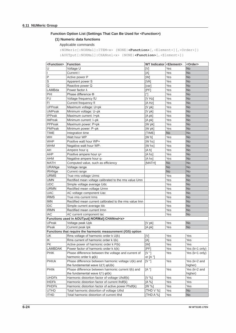
6-24 IM WT310E-17EN
Function Option List (Settings That Can Be Used for <Function>)(1) Numeric data functions Applicable commands
:NUMeric[:NORMal]:ITEM<x> {NONE|<Function>[,<Element>][,<Order>]}:AOUTput[:NORMal]:CHANnel<x> {NONE|<Function>[,<Element>]}
<Function> Function WT Indicator <Element> <Order>U VoltageU [V] Yes NoI Current I [A] Yes NoP Active power P [W] Yes NoS ApparentpowerS [VA] Yes NoQ ReactivepowerQ [var] Yes NoLAMBda Powerfactorλ [PF] Yes NoPHI PhasedifferenceΦ [°] Yes NoFU VoltagefrequencyfU [VHz] Yes NoFI Current frequency fI [A Hz] Yes NoUPPeak Maximumvoltage:U+pk [Vpk] Yes NoUMPeak Minimumvoltage:U–pk [Vpk] Yes NoIPPeak Maximumcurrent:I+pk [A pk] Yes NoIMPeak Minimumcurrent:I–pk [A pk] Yes NoPPPeak Maximumpower:P+pk [W pk] Yes NoPMPeak Minimumpower:P–pk [W pk] Yes NoTIME Integration time [TIME] No NoWH Watt hour WP [W h] Yes NoWHP PositivewatthourWP+ [W h±] Yes NoWHM NegativewatthourWP- [W h±] Yes NoAH Ampere hour q [A h] Yes NoAHP Positiveamperehourq+ [A h±] Yes NoAHM Negativeamperehourq- [A h±] Yes NoMATH Computed value, such as efficiency [MATH] No NoURANge Voltagerange No NoIRANge Current range No NoURMS True rms voltage Urms Yes NoUMN RectifiedmeanvoltagecalibratedtothermsvalueUmn Yes NoUDC SimplevoltageaverageUdc Yes NoURMN RectifiedmeanvoltageUrmn Yes NoUAC AC voltage component Uac Yes NoIRMS True rms current Irms Yes NoIMN RectifiedmeancurrentcalibratedtothermsvalueImn Yes NoIDC SimplecurrentaverageIdc Yes NoIRMN RectifiedmeancurrentIrmn Yes NoIAC AC current component Iac Yes NoFunctionsusedinAOUTput[:NORMal]:CHANnel<x>UPeak VoltagepeakUpk [Vpk] Yes NoIPeak Current peak Ipk [A pk] Yes NoFunctions that require the harmonic measurement (/G5) optionUK RmsvoltageofharmonicorderkU(k) [V] Yes YesIK RmscurrentofharmonicorderkI(k) [A] Yes YesPK Active power of harmonic order k P(k) [W] Yes YesLAMBDAK Powerfactorofharmonicorderkλ(k) [PF] Yes Yes (k=1 only)PHIK Phase difference between the voltage and current of
harmonicorderkφ(k)[V°]or [A °]
Yes Yes (k=1 only)
PHIUk Phase difference between harmonic voltage U(k) and thefundamentalwaveU(1)φU(k)
[V°] Yes Yes (k=2 and higher)
PHIIk Phase difference between harmonic current I(k) and thefundamentalwaveI(1)φI(k)
[A °] Yes Yes (k=2 and higher)
UHDFk Harmonic distortion factor of voltage Uhdf(k) [V%] Yes YesIHDFk Harmonic distortion factor of current Ihdf(k) [A%] Yes YesPHDFk Harmonic distortion factor of active power Phdf(k) [W%] Yes YesUTHD Total harmonic distortion of voltage Uthd [THDV%] Yes NoITHD Total harmonic distortion of current Ithd [THDA%] Yes No
6.11 NUMeric Group
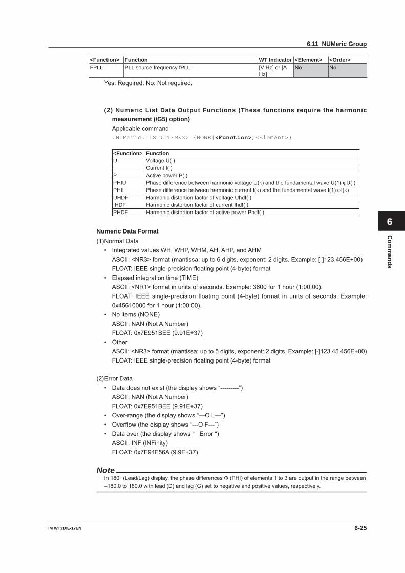
6-25IM WT310E-17EN
Com
mands
1
2
3
4
5
6
7
8
9
App
Index
<Function> Function WT Indicator <Element> <Order>FPLL PLL source frequency fPLL [VHz]or[A
Hz]No No
Yes:Required.No:Notrequired.
(2) Numeric List Data Output Functions (These functions require the harmonic measurement (/G5) option)
Applicable command:NUMeric:LIST:ITEM<x> {NONE|<Function>,<Element>}
<Function> FunctionU VoltageU()I Current I( )P Active power P( )PHIU PhasedifferencebetweenharmonicvoltageU(k)andthefundamentalwaveU(1)φU()PHII PhasedifferencebetweenharmoniccurrentI(k)andthefundamentalwaveI(1)φI(k)UHDF Harmonic distortion factor of voltage Uhdf( )IHDF Harmonic distortion factor of current Ihdf( )PHDF Harmonic distortion factor of active power Phdf( )
Numeric Data Format(1)NormalData
• IntegratedvaluesWH,WHP,WHM,AH,AHP,andAHM ASCII:<NR3>format(mantissa:upto6digits,exponent:2digits.Example:[-]123.456E+00) FLOAT:IEEEsingle-precisionfloatingpoint(4-byte)format• Elapsedintegrationtime(TIME) ASCII:<NR1>formatinunitsofseconds.Example:3600for1hour(1:00:00). FLOAT: IEEEsingle-precision floatingpoint (4-byte) format in units of seconds.Example:
0x45610000for1hour(1:00:00).• Noitems(NONE) ASCII:NAN(NotANumber) FLOAT:0x7E951BEE(9.91E+37)• Other ASCII:<NR3>format(mantissa:upto5digits,exponent:2digits.Example:[-]123.45.456E+00) FLOAT:IEEEsingle-precisionfloatingpoint(4-byte)format
(2) Error Data• Datadoesnotexist(thedisplayshows“---------”) ASCII:NAN(NotANumber) FLOAT:0x7E951BEE(9.91E+37)• Over-range(thedisplayshows“---OL---”)• Overflow(thedisplayshows“---OF---”)• Dataover(thedisplayshows“Error“) ASCII:INF(INFinity) FLOAT:0x7E94F56A(9.9E+37)
NoteIn180°(Lead/Lag)display,thephasedifferencesΦ(PHI)ofelements1to3areoutputintherangebetween–180.0to180.0withlead(D)andlag(G)settonegativeandpositivevalues,respectively.
6.11 NUMeric Group
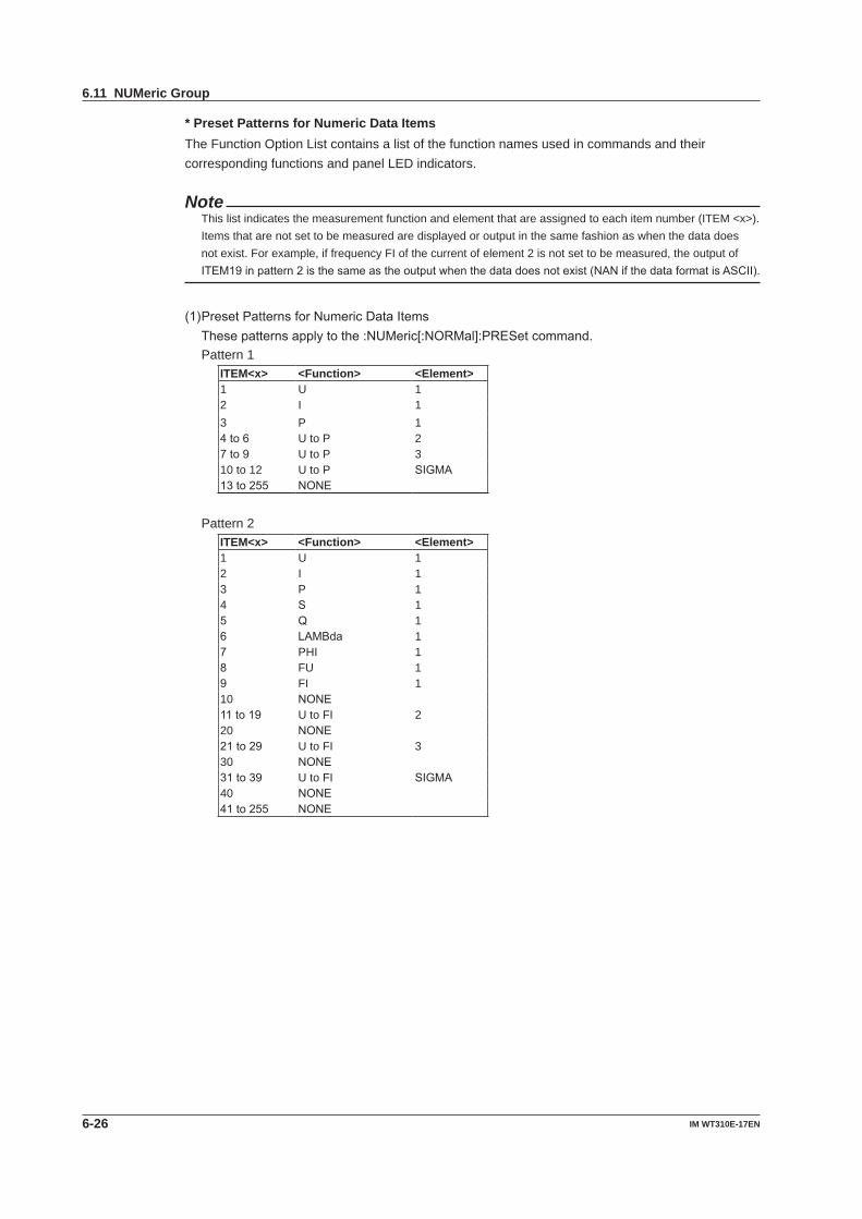
6-26 IM WT310E-17EN
* Preset Patterns for Numeric Data Items The Function Option List contains a list of the function names used in commands and their
corresponding functions and panel LED indicators.
NoteThis list indicates the measurement function and element that are assigned to each item number (ITEM <x>). Items that are not set to be measured are displayed or output in the same fashion as when the data does not exist. For example, if frequency FI of the current of element 2 is not set to be measured, the output of ITEM19inpattern2isthesameastheoutputwhenthedatadoesnotexist(NANifthedataformatisASCII).
(1)PresetPatternsforNumericDataItemsThesepatternsapplytothe:NUMeric[:NORMal]:PRESetcommand.Pattern 1
ITEM<x> <Function> <Element>1 U 12 I 13 P 14to6 U to P 27to9 U to P 310 to 12 U to P SIGMA13to255 NONE
Pattern 2ITEM<x> <Function> <Element>1 U 12 I 13 P 14 S 15 Q 16 LAMBda 17 PHI 18 FU 19 FI 110 NONE11to19 U to FI 220 NONE21to29 U to FI 330 NONE31to39 U to FI SIGMA40 NONE41to255 NONE
6.11 NUMeric Group

6-27IM WT310E-17EN
Com
mands
1
2
3
4
5
6
7
8
9
App
Index
Pattern 3ITEM<x> <Function> <Element>1 U 12 I 13 P 14 S 15 Q 16 LAMBda 17 PHI 18 FU 19 FI 110 UPPeak 111 UMPeak 112 IPPeak 113 IMPeak 114 PPPeak 115 PMPeak 116to30 U to PMPeak 231to45 U to PMPeak 346to60 U to PMPeak SIGMA61to255 NONE
Pattern 4ITEM<x> <Function> <Element>1 U 12 I 13 P 14 S 15 Q 16 LAMBda 17 PHI 18 FU 19 FI 110 UPPeak 111 UMPeak 112 IPPeak 113 IMPeak 114 TIME 115 WH 116 WHP 117 WHM 118 AH 119 AHP 120 AHM 121 to 40 U to AHM 241to60 U to AHM 361to80 U to AHM SIGMA81to255 NONE
6.11 NUMeric Group
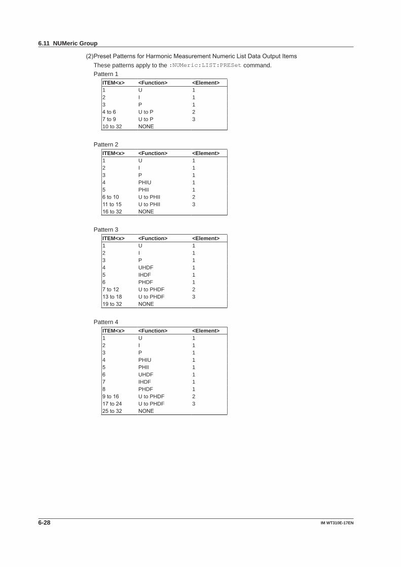
6-28 IM WT310E-17EN
(2)PresetPatternsforHarmonicMeasurementNumericListDataOutputItemsThese patterns apply to the :NUMeric:LIST:PRESet command.Pattern 1
ITEM<x> <Function> <Element>1 U 12 I 13 P 14to6 U to P 27to9 U to P 310 to 32 NONE
Pattern 2ITEM<x> <Function> <Element>1 U 12 I 13 P 14 PHIU 15 PHII 16to10 U to PHII 211to15 U to PHII 316to32 NONE
Pattern 3ITEM<x> <Function> <Element>1 U 12 I 13 P 14 UHDF 15 IHDF 16 PHDF 17to12 U to PHDF 213to18 U to PHDF 319to32 NONE
Pattern 4ITEM<x> <Function> <Element>1 U 12 I 13 P 14 PHIU 15 PHII 16 UHDF 17 IHDF 18 PHDF 19to16 U to PHDF 217to24 U to PHDF 325to32 NONE
6.11 NUMeric Group
6-29IM WT310E-17EN
Com
mands
1
2
3
4
5
6
7
8
9
App
Index
:RATEFunction Setsorqueriesthedataupdateinterval.Syntax :RATE {<Time>|AUTO}
:RATE?
<Time> = 100, 250, 500(ms), 1, 2, 5, 10, 20(s)
Example :RATE 250MS
:RATE? -> :RATE 250.0E-03
:RATE:AUTO?Function Queriesallapplicablesettingsforwhenthedata
update interval is set to Auto.Syntax :RATE:AUTO?
:RATE:AUTO:TIMeoutFunction Setsorqueriesthetimeoutforwhenthedata
update interval is set to Auto.Syntax :RATE:AUTO:TIMeout {<NRf>}
:RATE:AUTO:TIMeout?
<NRf> = 1, 5, 10, 20(s)Example :RATE:AUTO:TIMEOUT 1
:RATE:AUTO:TIMEOUT?
-> :RATE:AUTO:TIMEOUT 1
:RATE:AUTO:SYNChronizeFunction Setsorqueriesthesynchronizationsourcefor
when the data update interval is set to Auto.Syntax :RATE:AUTO:SYNChronize {U<x>|I<x>}
:RATE:AUTO:SYNChronize?
<x> = 1 to 3 (element)Example :RATE:AUTO:SYNCHRONIZE U1
:RATE:AUTO:SYNCHRONIZE?
-> :RATE:AUTO:SYNCHRONIZE U1
6.12 RATE Group
The command in this group deals with the data update interval. You can make the same settings and queries that you canbypressingSETUPonthefrontpanelandusingtheu.rAtEmenu.
6-30 IM WT310E-17EN
:RECall:NUMber?Function Queriesthenumberofblocksofmeasureddata
that is stored.Syntax :RECall:NUMber?
Example :RECALL:NUMBER? -> 600
:RECall[:NORMal]:VALue?Function Queriesthenumericdataatthespecifiedblock
number.Syntax :RECall[:NORMal]:VALue? {<NRf>}
<NRf>=1to9000(blocknumber)Description • Alwaysspecify<NRf>.Thenumericdataatthe
specified block number will be returned. • Ifyouomit<NRf>orspecifyanumbergreater
than the number of blocks that contain stored measureddata(thenumberreturnedby:RECall:NUMber?),theentirereturnednumericdatawillbe“NAN”(nodata).
• Theoutputitemsandformatarethesameasthoseof“:NUMeric[:NORMal]:VALue?(whentheitemnumberisnotspecified).”Tosettheoutputitemsandformat,usetheNUMericgroup commands.
:RECall:LIST:VALue?Function Queriesthenumericlistdataofharmonic
measurement at the specified block number.Syntax :RECall:LIST:VALue? {<NRf>}
<NRf>=1to600(blocknumber)Description • Thisisonlyvalidonmodelswiththeharmonic
measurement(/G5)option. • Alwaysspecify<NRf>.Thenumericlistdataat
the specified block number will be returned. • Ifyouomit<NRf>orspecifyanumbergreater
than the number of blocks that contain stored measureddata(thenumberreturnedby:RECall:NUMber?),theentirereturnednumericlistdatawillbe“NAN”(nodata).
• Theoutputitemsandformatarethesameasthoseof“:NUMeric:LIST:VALue?(whentheitemnumberisnotspecified).”Tosettheoutputitemsandformat,usetheNUMericgroup commands.
:RECall:PANelFunction Loads a setup parameter file.Syntax :RECall:PANel {<NRf>}
<NRf> = 1 to 4 (file number)
6.13 RECall Group
The commands in this group deal with outputting stored measured data and loading setup parameters. You can make the same settings that you can by pressing SAVE/LOAD on the front panel and using the LoAd menu. There are no front panel keys that output measured data that is stored.
6-31IM WT310E-17EN
Com
mands
1
2
3
4
5
6
7
8
9
App
Index
:STATus?Function Queriesallthesettingsforthecommunication
status feature.Syntax :STATus?
:STATus:CONDition?Function Queriesthecontentsofthecondition register.Syntax :STATus:CONDition?
Example :STATUS:CONDITION? -> 16
Description For information about the condition register, see chapter7,“StatusReports.”
:STATus:EESEFunction Setsorqueriestheextended event enable
register.Syntax :STATus:EESE <Register>
:STATus:EESE?
<Register> = 0 to 65535Example :STATUS:EESE #B0000000000000000
:STATus:EESE?
-> :STATUS:EESE 0
Description For information about the extended event enable register,seechapter7,“StatusReports.”
:STATus:EESR?Function Queriesthecontentsoftheextended event
register and clears the register.Syntax :STATus:EESR?
Example :STATUS:EESR? -> 0
Description For information about the extended event register, seechapter7,“StatusReports.”
:STATus:ERRor?Function Queriestheerrorcodeandmessageofthelast
error that has occurred (top of the error queue).Syntax :STATus:ERRor?
Example :STATUS:ERROR?
-> 113,"Underfined Header"
Description • Ifnoerrorshaveoccurred,0,”Noerror”isreturned.
• Youcanusethe:STATus:QMESsagecommand to specify whether the message is included.
:STATus:FILTer<x>Function Setsorqueriesthetransition filter.Syntax :STATus:FILTer<x> {RISE|FALL|BOTH|
NEVer}
:STATus:FILTer<x>?
<x>=1to16Example :STATUS:FILTER2 RISE
:STATus:FILTER2?
-> :STATUS:FILTER2 RISE
Description • Sethoweachbitintheconditionregistermustchange to trigger the setting of an event. If a bitissettoRISE,aneventissetwhenthebitchanges from 0 to 1.
• Forinformationaboutthetransitionfilter,seechapter7,“StatusReports.”
:STATus:QENableFunction Setsorquerieswhethermessagesotherthan
errorswillbestoredtotheerrorqueue(ON)ornot (OFF).
Syntax :STATus:QENable {<Boolean>}
:STATus:QENable?
Example :STATUS:QENABLE ON
:STATus:QENABLE?
-> :STATus:QENABLE 1
:STATus:QMESsageFunction Setsorquerieswhethermessageinformation
willbeattachedtotheresponsetotheSTATus:ERRor?query(ON/OFF).
Syntax :STATus:QMESsage {<Boolean>}
:STATus:QMESsage?
Example :STATUS:QMESSAGE ON
:STATus:QMESSAGE?
-> :STATus:QMESSAGE 1
:STATus:SPOLl?Function Executes serial polling.Syntax :STATus:SPOLl?
Example :STATUS:SPOLL? -> :STATUS:SPOLL 0
6.14 STATus group
The commands in this group are used to make settings and queries related to the status report. There are no front panelkeysthatcorrespondtothecommandsinthisgroup.Forinformationaboutstatusreports,seechapter7.
6-32 IM WT310E-17EN
:STORe?Function Queriesallstoragesettings.Syntax :STORe?
:STORe[:STATe]Function Setsorqueriesthestorageon/offstate.Syntax :STORe[:STATe] {<Boolean>}
:STORe:STATe?
Example :STORE:STATE ON
:STORE:STATE? -> :STORE:STATE 1
:STORe:INTervalFunction Setsorqueriesthestorage interval.Syntax :STORe:INTerval {<NRf>,<NRf>,<NRf>}
:STORe:INTerval?
{<NRf>,<NRf>,<NRf>} = 0,0,0 to 99,59,59 First <NRf> = 0 to 99 (hours) Second<NRf> = 0 to 59 (minutes) Third <NRf> = 0 to 59 (seconds)
Example :STORE:INTERVAL 0,0,0
:STORE:INTERVAL?
-> :STORE:INTERVAL 0,0,0
:STORe:PANelFunction Savessetup parameters to a file.Syntax :STORe:PANel {<NRf>}
<NRf> = 1 to 4 (file number)Example :STORE:PANEL 1
6.15 STORe Group
The commands in this group deal with storing measured data and saving setup parameters. You can make the same settingsandqueriesthatyoucanbypressingtheUTILITYkeyonthefrontpanelandthenusingtheStorEmenuorbypressingtheSAVE/LOADkeyandthenusingtheSAVEmenu.
6-33IM WT310E-17EN
Com
mands
1
2
3
4
5
6
7
8
9
App
Index
:SYSTem?Function Queriesallsystemsettings.Syntax :SYSTem?
:SYSTem:MODel?Function Queriesthemodel code.Syntax :SYSTem:MODel?
Example :SYSTEM:MODEL?
-> :SYSTEM:MODEL "WT310E"
Description ReturnstheModelitemoftheUtility->Infomenu.
:SYSTem:SUFFix?Function Queriesthesuffix code.Syntax :SYSTem:SUFFix?
Example :SYSTEM:SUFFIX?
-> :SYSTEM:SUFFIX "-C1-D/C7/EX1/G5/
DA4"
Description ReturnstheSuffixitemstringoftheUtility->Infomenu.
:SYSTem:SERial?Function Queriestheserial number.Syntax :SYSTem:SERial?
Example :SYSTEM:SERIAL?
-> :SYSTEM:SERIAL "123456789A"
Description ReturnstheNo.itemstringoftheUtility->Infomenu.
:SYSTem:VERsion[:FIRMware]?Function Queriesthefirmware version.Syntax :SYSTem:VERsion[:FIRMware]?
Example :SYSTEM:VERSION:FIRMWARE? -> "1.01"
Description ReturnstheVer.itemstringoftheUtility->Infomenu.
:SYSTem:KLOCkFunction Setsorqueriestheon/offstateofthekey
protection.Syntax :SYSTem:KLOCk {<Boolean>}
:SYSTem:KLOCk?
Example :SYSTEM:KLOCK OFF
:SYSTEM:KLOCK? -> :SYSTEM:KLOCK 0
:SYSTem:RESolutionFunction Setsorqueriesthenumeric data display
resolution.Syntax :SYSTem:RESolution {<NRf>}
:SYSTem:RESolution?
<NRf> = 4, 5 (digit)Example :SYSTEM:RESOLUTION 5
:SYSTEM:RESOLUTION?
-> :SYSTEM:RESOLUTION 5
:SYSTem:COMMunicate:COMMandFunction Setsorqueriesthecommand type.Syntax :SYSTem:COMMunicate:COMMand
{WT300E|WT300|WT200}
:SYSTem:COMMunicate:COMMand?
Example :SYSTEM:COMMUNICATE:COMMAND WT300E
:SYSTEM:COMMUNICATE:COMMAND?
-> :SYSTEM:COMMUNICATE:COMMAND WT300E
:SYSTem:COMMunicate:ETHernet:MACaddress?Function SetsorqueriestheEthernetMAC address.Syntax :SYSTem:COMMunicate:ETHernet
:MACaddress?
Example :SYSTEM:COMMUNICATE:ETHERNET
:MACADDRESS?
-> :SYSTEM:COMMUNICATE:ETHERNET:
MACADDRESS "000064_809_413"
Description This command is only valid on models with the Ethernetinterface(/C7)option.
6.16 SYSTem Group
The commands in this group deal with the system. You can make the same settings and queries that you can by pressingtheUTILITYkeyonthefrontpanelandthenusingtheinFoorrESomenuorbypressingtheKEYPROTECTorINTERFACEkey.
6-34 IM WT310E-17EN
*CAL?Function Executes zerocalibration(zero-level
compensation, the same operation as pressing CAL(SHIFT+SET))andqueriestheresult.
Syntax *CAL?
Example *CAL? -> 0
Description Ifthezero-levelcompensationendsnormally,0isreturned. If an error is detected, 1 is returned.
*CLSFunction Clears the standard event register, extended
event register, and error queue.Syntax *CLS
Example *CLS
Description • Ifthe*CLScommandislocatedimmediatelyafter the program message terminator, the output queue is also cleared.
• Forinformationabouteachregisterandqueue,seechapter7.
*ESEFunction Setsorqueriesthestandard event enable
register.Syntax *ESE {<NRf>}
*ESE?
<NRf> = 0 to 255Example *ESE 251
*ESE? -> 251
Description • Specifythevalueasasumofthevaluesofeach bit in decimal format.
• Forexample,specifying*ESE251willcausethe standard enable register to be set to 11111011. In this case, bit 2 of the standard eventregisterisdisabled.Thismeansthatbit5(ESB)ofthestatusbyteregisterisnotsetto1,even if a query error occurs.
• Thedefaultvalueis*ESE0(allbitsdisabled). • Aqueryusing*ESE?willnotclearthecontents
of the standard event enable register. • Forinformationaboutthestandardevent
enableregister,seepage7-4.
*ESR?Function Queriesandclearsthestandard event register.Syntax *ESR?
Example *ESR? -> 32
Description • Asumofthevaluesofeachbitisreturnedindecimal format.
• WhenanSRQissent,youcancheckwhattypes of events have occurred.
• Forexample,ifavalueof32isreturned,thisindicates that the standard event register is setto00100000.ThismeansthattheSRQoccurred due to a command syntax error.
• Aqueryusing*ESR?willclearthecontentsoftheStandardEventRegister.
• Forinformationaboutthestandardeventregister,seepage7-4.
*IDN?Function Queriestheinstrument model.Syntax *IDN?
Example *IDN? ->
YOKOGAWA,WT310E,123456789A,F1.01
Description • Theinformationisreturnedinthisform:<manufacture>, <model>, <serial number>, <firmware version>.
• Fordetailsonthemodel,see“CheckingthePackageContents”intheGettingStartedGuide,IMWT310E-02EN.
*OPCFunction Setsbit0(theOPCbit)ofthestandardevent
register to 1 upon the completion of the specified overlap command.
Syntax *OPC
Example *OPC
Description • Thisinstrumentdoesnothaveoverlapcommands. The OPC bit is always set to 1.
6.17 Common Command Group
Thecommands in thisgrouparedefined in IEEE488.2-1992andare independent fromthe instrument’s individualfunctions. There are no front panel keys that correspond to the commands in this group.
6-35IM WT310E-17EN
Com
mands
1
2
3
4
5
6
7
8
9
App
Index
*OPC?Function ReturnsASCIIcode1ifthespecifiedoverlap
command has finished.Syntax *OPC?
Example *OPC? -> 1
Description This instrument does not have overlap commands. 1 is always returned.
*OPT?Function Queriestheinstalled options.Syntax *OPT?
Example *OPT? -> C1,C7,EX1,G5,DA4
Description • ThiscommandreturnswhethertheGP-IB(C1),RS-232(C2),Ethernetcommunication(C7),externalcurrentsensorinput(EX1,2.5V/5V/10V),externalcurrentsensorinput(EX2,50mV/100mV/200mV/500mV/1V/2V),harmonicmeasurement(G5),4-channelD/Aoutput (DA4, for the WT310E and WT310EH), and12-channelD/Aoutput(DA12,fortheWT332E and WT333E) are available.
• The*OPT?querymustbethelastqueryofaprogram message.
An error occurs if there is a query after the *OPTquery.
*RSTFunction Initializes the settings.Syntax *RST
Example *RST
Description All settings except communication settings are reset to their factory default values. For details oninitialization,seesection8.2intheUser’sManual,IMWT310E-01EN.
*SREFunction Setsorqueriestheservice request enable
register value.Syntax *SRE {<NRf>}
*SRE?
<NRf> = 0 to 255Example *SRE 239
*SRE?
-> 175(becausethebit6,MSS,settingisignored)
Description • Specifythevalueasasumofthevaluesofeach bit in decimal format.
• Forexample,specifying*SRE239willcausethe standard enable register to be set to 11101111. In this case, bit 4 of the service request enable register is disabled. This means thatbit4(MAV)ofthestatusbyteregisterisnot set to 1, even if the output queue is not empty.
• Bit6(MSS)ofthestatusbyteregisteristheMSSbititselfandisthereforeignored.
• Thedefaultvalueis*SRE0(allbitsdisabled). • Aqueryusing*SRE?willnotclearthecontents
of the service request enable register. • Forinformationabouttheservicerequest
enableregister,seepage7-3.
*STB?Function QueriestheStatusByteRegistervalue.Syntax *STB?
Example *STB? -> 4
Description • Asumofthevaluesofeachbitisreturnedasadecimal value.
• Becausetheregisterisreadwithoutexecutingserialpolling,bit6isanMSSbit,notanRQSbit.
• Forexample,ifavalueof4isreturned,thisindicates that the status byte register is set to 00000100. This means that the error queue is not empty (in other words, an error occurred).
• Aqueryusing*STB?willnotclearthecontentsof the status byte register.
• Forinformationaboutthestatusbyteregister,seepage7-3.
*TRGFunction Executes single measurement (the same
operationaswhenSINGLE(SHIFT+HOLD)ispressed).
Syntax *TRG
Example *TRG
Description Amulti-linemessageGET(GroupExecuteTrigger) will perform the same operation as this command.
6.17 Common Command Group
6-36 IM WT310E-17EN
*TST?Function Executes a self-testandqueriestheresult.Syntax *TST?
Example *TST? -> 0
Description • Theself-testconsistsoftestsofeachkindofinternal memory.
• Thiscommandreturns0iftheself-testissuccessful and 1 if it is not.
• Ittakesapproximately6secondsforthetesttocomplete. When receiving a response from this instrument, set the timeout to a relatively large value.
*WAIFunction Holds the execution of the subsequent command
until the completion of the specified overlap command.
Syntax *WAI
Example *WAI
Description This instrument does not have overlap commands. This command will be ignored.
6.17 Common Command Group
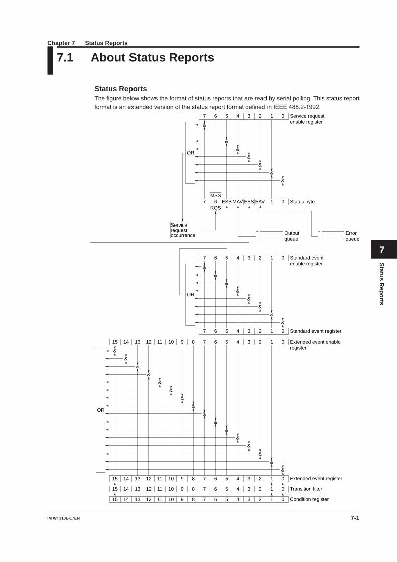
7-1IM WT310E-17EN
Status Reports
Chapter 7 Status Reports
1
2
3
4
5
6
7
8
9
App
Index
7.1 About Status Reports
Status ReportsThe figure below shows the format of status reports that are read by serial polling. This status report formatisanextendedversionofthestatusreportformatdefinedinIEEE488.2-1992.
15 14 13 12 11 10 9 8 7 6 5 4 3 2 1 0
15 14 13 12 11 10 9 8 7 6 5 4 3 2 1 0
15 14 13 12 11 10 9 8 7 6 5 4 3 2 1 0
Condition register
Transition filter
Extended event register
&
15 14 13 12 11 10 9 8 7 6 5 4 3 2 1 0 Extended event enable register
&&
&&
&&
&&
&&
&&
&&
&
7 6 5 4 3 2 1 0 Standard event register
&&
&&
&&
&&
7 6 5 4 3 2 1 0 Standard event enable register
OR
OR
7 6 ESB MAV EES EAV 1 0 Status byteMSS
RQS
Output queue
Error queue
Service request occurrence
&&
&&
&&
&
7 6 5 4 3 2 1 0 Service request enable register
OR
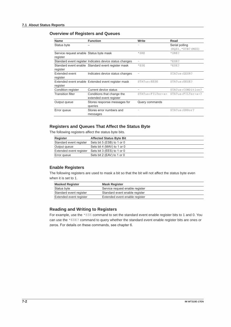
7-2 IM WT310E-17EN
7.1 About Status Reports
Overview of Registers and QueuesName Function Write ReadStatusbyte – – Serialpolling
(RQS), *STB?(MSS)Servicerequestenableregister
Statusbytemask *SRE *SRE?
Standardeventregister Indicates device status changes – *ESR?Standardeventenableregister
Standardeventregistermask *ESE *ESE?
Extended event register
Indicates device status changes – STATus:EESR?
Extended event enable register
Extended event register mask STATus:EESE STATus:EESE?
Condition register Current device status – STATus:CONDition?Transition filter Conditions that change the
extended event registerSTATus:FILTer<x> STATus:FILTer<x>?
Output queue Storesresponsemessagesforqueries
Querycommands
Error queue Storeserrornumbersandmessages
– STATus:ERRor?
Registers and Queues That Affect the Status ByteThe following registers affect the status byte bits.
Register Affected Status Byte BitStandardeventregister Setsbit5(ESB)to1or0Output queue Setsbit4(MAV)to1or0Extended event register Setsbit3(EES)to1or0Error queue Setsbit2(EAV)to1or0
Enable RegistersThe following registers are used to mask a bit so that the bit will not affect the status byte even when it is set to 1.
Masked Register Mask RegisterStatusbyte ServicerequestenableregisterStandardeventregister StandardeventenableregisterExtended event register Extended event enable register
Reading and Writing to RegistersFor example, use the *ESE command to set the standard event enable register bits to 1 and 0. You can use the *ESE? command to query whether the standard event enable register bits are ones or zeros.Fordetailsonthesecommands,seechapter6.
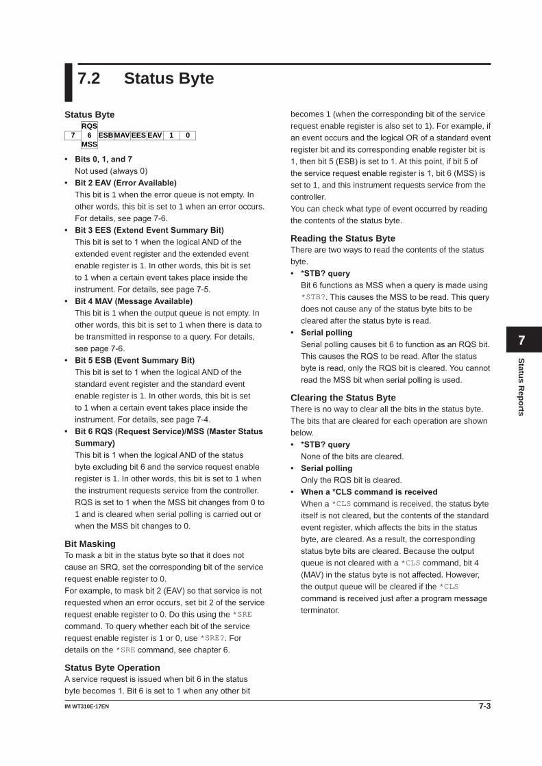
7-3IM WT310E-17EN
Status Reports
1
2
3
4
5
6
7
8
9
App
Index
7.2 Status Byte
becomes 1 (when the corresponding bit of the service request enable register is also set to 1). For example, if aneventoccursandthelogicalORofastandardeventregister bit and its corresponding enable register bit is 1,thenbit5(ESB)issetto1.Atthispoint,ifbit5oftheservicerequestenableregisteris1,bit6(MSS)isset to 1, and this instrument requests service from the controller.You can check what type of event occurred by reading the contents of the status byte.
Reading the Status ByteThere are two ways to read the contents of the status byte.• *STB?query Bit6functionsasMSSwhenaqueryismadeusing
*STB?.ThiscausestheMSStoberead.Thisquerydoes not cause any of the status byte bits to be cleared after the status byte is read.
• Serialpolling Serialpollingcausesbit6tofunctionasanRQSbit.
ThiscausestheRQStoberead.Afterthestatusbyteisread,onlytheRQSbitiscleared.YoucannotreadtheMSSbitwhenserialpollingisused.
Clearing the Status ByteThere is no way to clear all the bits in the status byte. The bits that are cleared for each operation are shown below.• *STB?query Noneofthebitsarecleared.• Serialpolling OnlytheRQSbitiscleared.• Whena*CLScommandisreceived When a *CLS command is received, the status byte
itself is not cleared, but the contents of the standard event register, which affects the bits in the status byte, are cleared. As a result, the corresponding statusbytebitsarecleared.Becausetheoutputqueue is not cleared with a *CLS command, bit 4 (MAV)inthestatusbyteisnotaffected.However,the output queue will be cleared if the *CLS commandisreceivedjustafteraprogrammessageterminator.
Status Byte
7 6 ESBMAV EES EAV 1 0RQS
MSS
• Bits0,1,and7Notused(always0)
• Bit2EAV(ErrorAvailable) This bit is 1 when the error queue is not empty. In
other words, this bit is set to 1 when an error occurs. Fordetails,seepage7-6.
• Bit3EES(ExtendEventSummaryBit) Thisbitissetto1whenthelogicalANDofthe
extended event register and the extended event enable register is 1. In other words, this bit is set to 1 when a certain event takes place inside the instrument.Fordetails,seepage7-5.
• Bit4MAV(MessageAvailable) This bit is 1 when the output queue is not empty. In
other words, this bit is set to 1 when there is data to be transmitted in response to a query. For details, seepage7-6.
• Bit5ESB(EventSummaryBit) Thisbitissetto1whenthelogicalANDofthe
standard event register and the standard event enable register is 1. In other words, this bit is set to 1 when a certain event takes place inside the instrument.Fordetails,seepage7-4.
• Bit6RQS(RequestService)/MSS(MasterStatusSummary)
Thisbitis1whenthelogicalANDofthestatusbyteexcludingbit6andtheservicerequestenableregister is 1. In other words, this bit is set to 1 when the instrument requests service from the controller.
RQSissetto1whentheMSSbitchangesfrom0to1 and is cleared when serial polling is carried out or whentheMSSbitchangesto0.
Bit MaskingTo mask a bit in the status byte so that it does not causeanSRQ,setthecorrespondingbitoftheservicerequest enable register to 0.Forexample,tomaskbit2(EAV)sothatserviceisnotrequested when an error occurs, set bit 2 of the service request enable register to 0. Do this using the *SRE command. To query whether each bit of the service request enable register is 1 or 0, use *SRE?. For details on the *SREcommand,seechapter6.
Status Byte OperationAservicerequestisissuedwhenbit6inthestatusbytebecomes1.Bit6issetto1whenanyotherbit
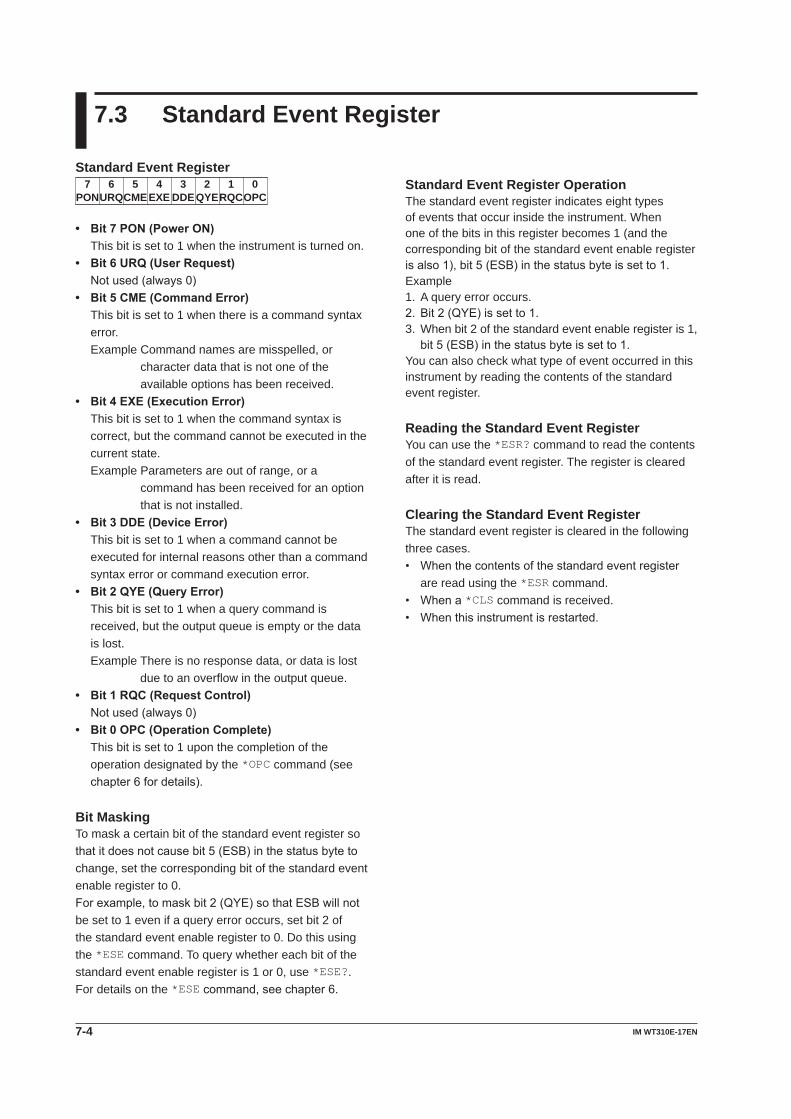
7-4 IM WT310E-17EN
7.3 Standard Event Register
Standard Event Register OperationThe standard event register indicates eight types of events that occur inside the instrument. When one of the bits in this register becomes 1 (and the corresponding bit of the standard event enable register isalso1),bit5(ESB)inthestatusbyteissetto1.Example1. A query error occurs.2.Bit2(QYE)issetto1.3. When bit 2 of the standard event enable register is 1,
bit5(ESB)inthestatusbyteissetto1.You can also check what type of event occurred in this instrument by reading the contents of the standard event register.
Reading the Standard Event RegisterYou can use the *ESR? command to read the contents of the standard event register. The register is cleared after it is read.
Clearing the Standard Event RegisterThe standard event register is cleared in the following three cases.• Whenthecontentsofthestandardeventregister
are read using the *ESR command.• Whena*CLS command is received.• Whenthisinstrumentisrestarted.
Standard Event Register
URQ6
PON7 5 4 3 2 1 0
CME EXE DDE QYERQCOPC
• Bit7PON(PowerON) This bit is set to 1 when the instrument is turned on.• Bit6URQ(UserRequest) Notused(always0)• Bit5CME(CommandError) This bit is set to 1 when there is a command syntax
error.Example Command names are misspelled, or
character data that is not one of the available options has been received.
• Bit4EXE(ExecutionError) This bit is set to 1 when the command syntax is
correct, but the command cannot be executed in the current state.Example Parameters are out of range, or a
command has been received for an option that is not installed.
• Bit3DDE(DeviceError) This bit is set to 1 when a command cannot be
executed for internal reasons other than a command syntax error or command execution error.
• Bit2QYE(QueryError) This bit is set to 1 when a query command is
received, but the output queue is empty or the data is lost.Example There is no response data, or data is lost
due to an overflow in the output queue.• Bit1RQC(RequestControl) Notused(always0)• Bit0OPC(OperationComplete) This bit is set to 1 upon the completion of the
operation designated by the *OPC command (see chapter6fordetails).
Bit MaskingTo mask a certain bit of the standard event register so thatitdoesnotcausebit5(ESB)inthestatusbytetochange, set the corresponding bit of the standard event enable register to 0.Forexample,tomaskbit2(QYE)sothatESBwillnotbe set to 1 even if a query error occurs, set bit 2 of the standard event enable register to 0. Do this using the *ESE command. To query whether each bit of the standard event enable register is 1 or 0, use *ESE?. For details on the *ESEcommand,seechapter6.
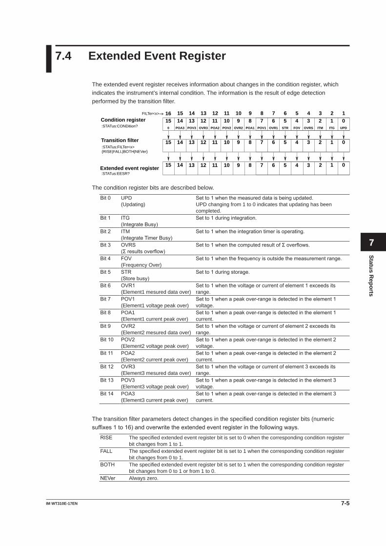
7-5IM WT310E-17EN
Status Reports
1
2
3
4
5
6
7
8
9
App
Index
7.4 Extended Event Register
The extended event register receives information about changes in the condition register, which indicates the instrument’s internal condition. The information is the result of edge detection performed by the transition filter.
OVR1
6POA1
7 5 4 3 2 1 0STR FOV OVRS ITM ITG UPDPOV2POA2
8OVR2
9POV1
1011OVR3
12POV3
13POA3
140
15
67 5 4 3 2 1 089101112131415
Condition register:STATus:CONDition?
Transition filter
01415Extended event register 167 5 4 38910111213 2
67 5 4 3 2 18910111213141516
:STATus:FILTer<x>{RISE|FALL|BOTH|NEVer}
:STATus:EESR?
FILTer<x>
The condition register bits are described below.
Bit0 UPD(Updating)
Setto1whenthemeasureddataisbeingupdated.UPD changing from 1 to 0 indicates that updating has been completed.
Bit1 ITG(IntegrateBusy)
Setto1duringintegration.
Bit2 ITM(IntegrateTimerBusy)
Setto1whentheintegrationtimerisoperating.
Bit3 OVRS(Σresultsoverflow)
Setto1whenthecomputedresultofΣoverflows.
Bit4 FOV(Frequency Over)
Setto1whenthefrequencyisoutsidethemeasurementrange.
Bit5 STR(Storebusy)
Setto1duringstorage.
Bit6 OVR1(Element1 mesured data over)
Setto1whenthevoltageorcurrentofelement1exceedsitsrange.
Bit7 POV1(Element1 voltage peak over)
Setto1whenapeakover-rangeisdetectedintheelement1voltage.
Bit8 POA1(Element1 current peak over)
Setto1whenapeakover-rangeisdetectedintheelement1current.
Bit9 OVR2(Element2 mesured data over)
Setto1whenthevoltageorcurrentofelement2exceedsitsrange.
Bit10 POV2(Element2 voltage peak over)
Setto1whenapeakover-rangeisdetectedintheelement2voltage.
Bit11 POA2(Element2 current peak over)
Setto1whenapeakover-rangeisdetectedintheelement2current.
Bit12 OVR3(Element3 mesured data over)
Setto1whenthevoltageorcurrentofelement3exceedsitsrange.
Bit13 POV3(Element3 voltage peak over)
Setto1whenapeakover-rangeisdetectedintheelement3voltage.
Bit14 POA3(Element3 current peak over)
Setto1whenapeakover-rangeisdetectedintheelement3current.
The transition filter parameters detect changes in the specified condition register bits (numeric suffixes1to16)andoverwritetheextendedeventregisterinthefollowingways.
RISE The specified extended event register bit is set to 0 when the corresponding condition register bit changes from 1 to 1.
FALL The specified extended event register bit is set to 1 when the corresponding condition register bit changes from 0 to 1.
BOTH The specified extended event register bit is set to 1 when the corresponding condition register bit changes from 0 to 1 or from 1 to 0.
NEVer Always zero.
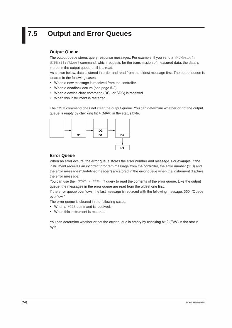
7-6 IM WT310E-17EN
7.5 Output and Error Queues
Output QueueThe output queue stores query response messages. For example, if you send a :NUMeric[:NORMal]:VALue? command, which requests for the transmission of measured data, the data is stored in the output queue until it is read.As shown below, data is stored in order and read from the oldest message first. The output queue is cleared in the following cases.• Whenanewmessageisreceivedfromthecontroller.• Whenadeadlockoccurs(seepage5-2).• Whenadeviceclearcommand(DCLorSDC)isreceived.• Whenthisinstrumentisrestarted.
The *CLS command does not clear the output queue. You can determine whether or not the output queueisemptybycheckingbit4(MAV)inthestatusbyte.
D1D2D1 D2
D1
Error QueueWhen an error occurs, the error queue stores the error number and message. For example, if the instrument receives an incorrect program message from the controller, the error number (113) and theerrormessage(“Undefinedheader”)arestoredintheerrorqueuewhentheinstrumentdisplaysthe error message.You can use the :STATus:ERRor? query to read the contents of the error queue. Like the output queue, the messages in the error queue are read from the oldest one first.Iftheerrorqueueoverflows,thelastmessageisreplacedwiththefollowingmessage:350,“Queueoverflow.”The error queue is cleared in the following cases.• Whena*CLS command is received.• Whenthisinstrumentisrestarted.
Youcandeterminewhetherornottheerrorqueueisemptybycheckingbit2(EAV)inthestatusbyte.
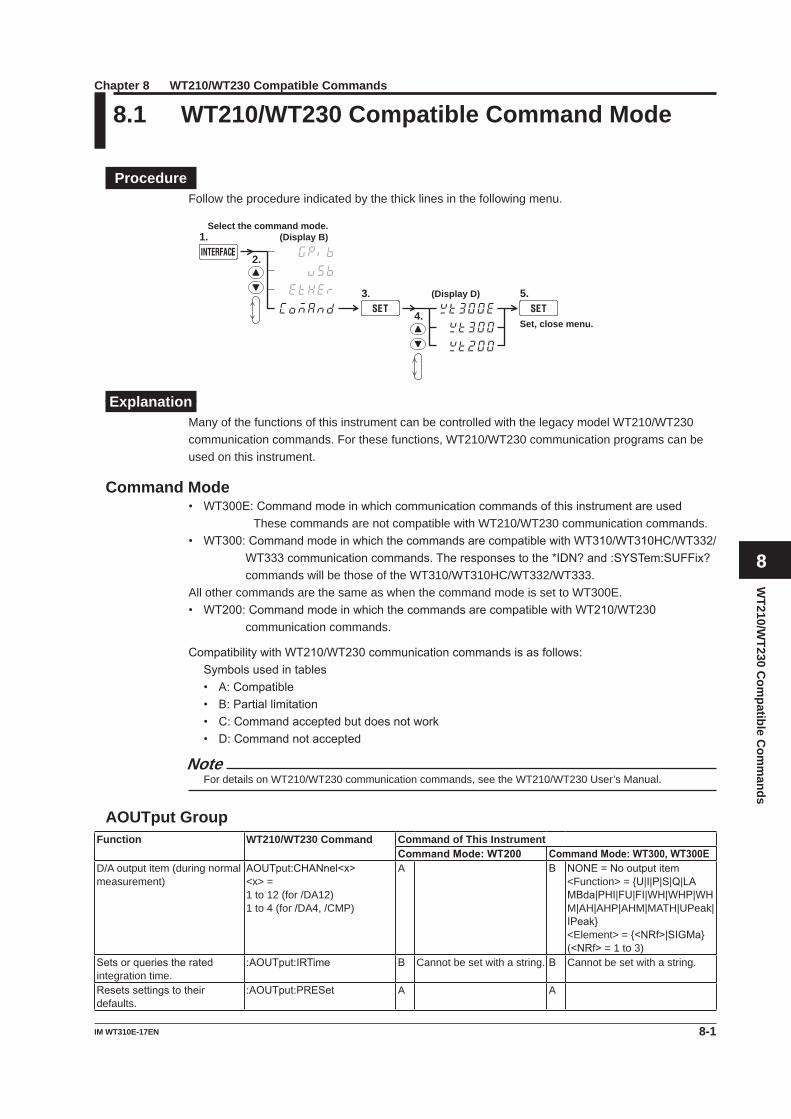
8-1IM WT310E-17EN
WT210/W
T230 Com
patible Com
mands
1
2
3
4
5
6
7
8
9
App
Index
8.1 WT210/WT230 Compatible Command Mode
ProcedureFollow the procedure indicated by the thick lines in the following menu.
2.
Select the command mode. (Display B) 1.
3.
4.
(Display D) 5.
Set, close menu.
ExplanationMany of the functions of this instrument can be controlled with the legacy model WT210/WT230 communication commands. For these functions, WT210/WT230 communication programs can be used on this instrument.
Command Mode• WT300E:Commandmodeinwhichcommunicationcommandsofthisinstrumentareused
These commands are not compatible with WT210/WT230 communication commands.• WT300:CommandmodeinwhichthecommandsarecompatiblewithWT310/WT310HC/WT332/
WT333communicationcommands.Theresponsestothe*IDN?and:SYSTem:SUFFix?commands will be those of the WT310/WT310HC/WT332/WT333.
All other commands are the same as when the command mode is set to WT300E.• WT200:CommandmodeinwhichthecommandsarecompatiblewithWT210/WT230
communication commands.
CompatibilitywithWT210/WT230communicationcommandsisasfollows:Symbolsusedintables• A:Compatible• B:Partiallimitation• C:Commandacceptedbutdoesnotwork• D:Commandnotaccepted
NoteFor details on WT210/WT230 communication commands, see the WT210/WT230 User’s Manual.
AOUTput GroupFunction WT210/WT230 Command Command of This Instrument
CommandMode:WT200 CommandMode:WT300,WT300ED/A output item (during normal measurement)
AOUTput:CHANnel<x><x> =1 to 12 (for /DA12)1 to 4 (for /DA4, /CMP)
A B NONE=Nooutputitem<Function> = {U|I|P|S|Q|LA MBda|PHI|FU|FI|WH|WHP|WHM|AH|AHP|AHM|MATH|UPeak|IPeak}<Element> = {<NRf>|SIGMa}(<NRf> = 1 to 3)
Setsorqueriestheratedintegration time.
:AOUTput:IRTime B Cannot be set with a string. B Cannot be set with a string.
Resetssettingstotheirdefaults.
:AOUTput:PRESet A A
Chapter 8 WT210/WT230 Compatible Commands
8-2 IM WT310E-17EN
COMMunicate groupFunction WT210/WT230 Command Command of This Instrument
CommandMode:WT200 CommandMode:WT300,WT300ESetsorquerieswhetherheaders are attached to response data.
:COMMunicate:HEADer A A
Sets/clearslocallockout. :COMMunicate:LOCKout A ASetsremoteorlocalmode. :COMMunicate:REMote A AQueriestheline-specificstatus. :COMMunicate:STATus? A ASetsorquerieswhetherqueryresponses are returned in full or abbreviated form.
:COMMunicate:VERBose A A
Waits for the specified extended event to occur.
:COMMunicate:WAIT A A
Creates a response for the specified extended event.
:COMMunicate:WAIT? A A
CONFigure GroupFunction WT210/WT230 Command Command of This Instrument
CommandMode:WT200 CommandMode:WT300,WT300EQueriesallaveragingsettings. [:CONFigure]:AVERaging? A D :MEASure:AVERaging?Setsorqueriestheon/offstateof averaging.
[:CONFigure]:AVERaging[:STATe]
A D :MEASure:AVERaging[:STATe]
Setsorqueriestheaveragingtype.
[:CONFigure]:AVERaging:TYPE
A D :MEASure:AVERaging:TYPE:MEASure:AVERaging:COUNt
Setsorqueriesthecrestfactor. [:CONFigure]:CFACtor A D [:INPut]:CFACtorQueriesallcurrentrangesettings.
[:CONFigure]:CURRent? A D [:INPut]:CURRent?
Setsorqueriesthecurrentauto range on/off state.
[:CONFigure]:CURRent:AUTO A D [:INPut]:CURRent:AUTO
Queriesallexternalcurrentsensor scaling constant settings.
[:CONFigure]:CURRent:ESCaling?
A D [:INPut]:CURRent:SRATio?
Setstheexternalcurrentsensor scaling constant on all elements at once.
[:CONFigure]:CURRent:ESCaling[:ALL]
A You can set the external current sensor scaling constant using the “A/FS(mV)”form,justlikethe WT210/WT230 computation method.
FS=Externalcurrentsensor range rating
D [:INPut]:CURRent:SRATio[:ALL]
Setsorqueriestheexternalcurrent sensor scaling constant of an element.
[:CONFigure]:CURRent:ESCaling:ELEMent<x>
A D [:INPut]:CURRent:SRATio:ELEMent<x>
Setsorqueriesthecurrentrange.
[:CONFigure]:CURRent:RANGe
A D [:INPut]:CURRent:RANGe
Setsorqueriesthefrequencyfilter on/off state.
[:CONFigure]:FILTer A D [:INPut]:FILTer:FREQuency
Setsorqueriesthelinefilteron/off state.
[:CONFigure]:LFILter A D [:INPut]:FILTer:LINE
SetsorqueriestheMAXholdon/off state.
[:CONFigure]:MHOLd[:STATe] A D :MEASure:MHOLd
Setsorqueriesthemeasurement mode.
[:CONFigure]:MODE A D [:INPut]:MODE
Queriesallscalingsettings. [:CONFigure]:SCALing? A D [:INPut]:SCALing?Queriesthe{voltage|current|power}scalingconstant.
[:CONFigure]:SCALing:{PT|CT|SFACtor}?
A D [:INPut]:SCALing:{VT|CT|SFACtor}?
Setsthe{voltage|current|power}scaling constant on all elements at once.
[:CONFigure]:SCALing:{PT|CT|SFACtor} [:ALL]
A D [:INPut]:SCALing:{VT|CT|SFACtor}[:ALL]
Setsorqueriesthe{voltage|current|power}scalingconstant of an element.
[:CONFigure]:SCALing:{PT|CT|SFACtor}:ELEMent<x>
A D [:INPut]:SCALing:{VT|CT|SFACtor}:ELEMent<x>
Setsorqueriesthescalingon/off state.
[:CONFigure]:SCALing[:STATe]
A D [:INPut]:SCALing[:STATe]
8.1 WT210/WT230 Compatible Mode
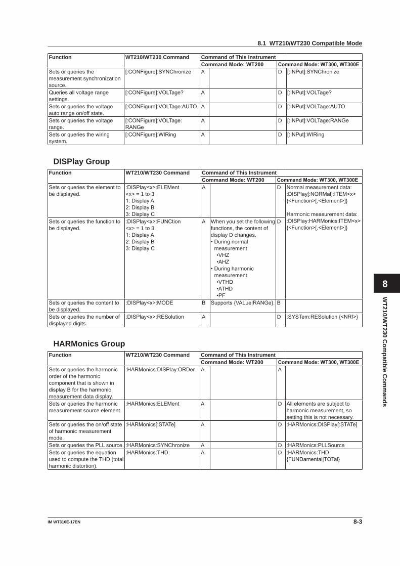
8-3IM WT310E-17EN
WT210/W
T230 Com
patible Com
mands
1
2
3
4
5
6
7
8
9
App
Index
Function WT210/WT230 Command Command of This InstrumentCommandMode:WT200 CommandMode:WT300,WT300E
Setsorqueriesthemeasurement synchronization source.
[:CONFigure]:SYNChronize A D [:INPut]:SYNChronize
Queriesallvoltagerangesettings.
[:CONFigure]:VOLTage? A D [:INPut]:VOLTage?
Setsorqueriesthevoltageauto range on/off state.
[:CONFigure]:VOLTage:AUTO A D [:INPut]:VOLTage:AUTO
Setsorqueriesthevoltagerange.
[:CONFigure]:VOLTage:RANGe
A D [:INPut]:VOLTage:RANGe
Setsorqueriesthewiringsystem.
[:CONFigure]:WIRing A D [:INPut]:WIRing
DISPlay GroupFunction WT210/WT230 Command Command of This Instrument
CommandMode:WT200 CommandMode:WT300,WT300ESetsorqueriestheelementtobe displayed.
:DISPlay<x>:ELEMent<x> = 1 to 31:DisplayA2:DisplayB3:DisplayC
A D Normalmeasurementdata::DISPlay[:NORMal]:ITEM<x>{<Function>[,<Element>]}
Harmonicmeasurementdata::DISPlay:HARMonics:ITEM<x>{<Function>[,<Element>]}
Setsorqueriesthefunctiontobe displayed.
:DISPlay<x>:FUNCtion<x> = 1 to 31:DisplayA2:DisplayB3:DisplayC
A When you set the following functions, the content of display D changes.•Duringnormal
measurement•VHZ•AHZ
•Duringharmonicmeasurement•VTHD•ATHD•PF
D
Setsorqueriesthecontenttobe displayed.
:DISPlay<x>:MODE B Supports{VALue|RANGe}. B
Setsorqueriesthenumberofdisplayed digits.
:DISPlay<x>:RESolution A D :SYSTem:RESolution{<NRf>}
HARMonics GroupFunction WT210/WT230 Command Command of This Instrument
CommandMode:WT200 CommandMode:WT300,WT300ESetsorqueriestheharmonicorder of the harmonic component that is shown in displayBfortheharmonicmeasurement data display.
:HARMonics:DISPlay:ORDer A A
Setsorqueriestheharmonicmeasurement source element.
:HARMonics:ELEMent A D Allelementsaresubjecttoharmonic measurement, so setting this is not necessary.
Setsorqueriestheon/offstateof harmonic measurement mode.
:HARMonics[:STATe] A D :HARMonics:DISPlay[:STATe]
SetsorqueriesthePLLsource. :HARMonics:SYNChronize A D :HARMonics:PLLSourceSetsorqueriestheequationused to compute the THD (total harmonic distortion).
:HARMonics:THD A D :HARMonics:THD{FUNDamental|TOTal}
8.1 WT210/WT230 Compatible Mode
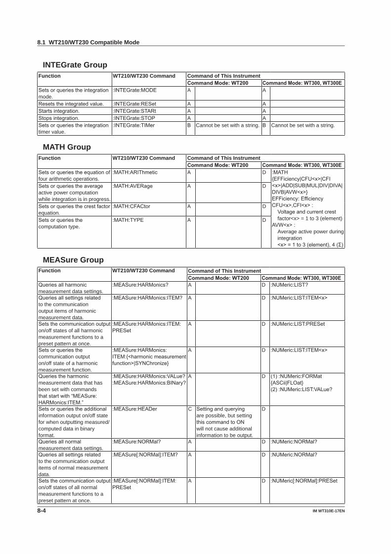
8-4 IM WT310E-17EN
INTEGrate GroupFunction WT210/WT230 Command Command of This Instrument
CommandMode:WT200 CommandMode:WT300,WT300ESetsorqueriestheintegrationmode.
:INTEGrate:MODE A A
Resetstheintegratedvalue. :INTEGrate:RESet A AStartsintegration. :INTEGrate:STARt A AStopsintegration. :INTEGrate:STOP A ASetsorqueriestheintegrationtimer value.
:INTEGrate:TIMer B Cannot be set with a string. B Cannot be set with a string.
MATH GroupFunction WT210/WT230 Command Command of This Instrument
CommandMode:WT200 CommandMode:WT300,WT300ESetsorqueriestheequationoffour arithmetic operations.
:MATH:ARIThmetic A D :MATH{EFFiciency|CFU<x>|CFI<x>|ADD|SUB|MUL|DIV|DIVA|DIVB|AVW<x>}EFFiciency:EfficiencyCFU<x>,CFI<x>:Voltageandcurrentcrestfactor<x> = 1 to 3 (element)
AVW<x>:Average active power during integration<x>=1to3(element),4(Σ)
Setsorqueriestheaverageactive power computation while integration is in progress.
:MATH:AVERage A D
Setsorqueriesthecrestfactorequation.
:MATH:CFACtor A D
Setsorqueriesthecomputation type.
:MATH:TYPE A D
MEASure GroupFunction WT210/WT230 Command Command of This Instrument
CommandMode:WT200 CommandMode:WT300,WT300EQueriesallharmonicmeasurement data settings.
:MEASure:HARMonics? A D :NUMeric:LIST?
Queriesallsettingsrelatedto the communication output items of harmonic measurement data.
:MEASure:HARMonics:ITEM? A D :NUMeric:LIST:ITEM<x>
Setsthecommunicationoutputon/off states of all harmonic measurement functions to a preset pattern at once.
:MEASure:HARMonics:ITEM:PRESet
A D :NUMeric:LIST:PRESet
Setsorqueriesthecommunication output on/off state of a harmonic measurement function.
:MEASure:HARMonics:ITEM:{<harmonicmeasurementfunction>|SYNChronize}
A D :NUMeric:LIST:ITEM<x>
Queriestheharmonicmeasurement data that has been set with commands thatstartwith“MEASure:HARMonics:ITEM.”
:MEASure:HARMonics:VALue? :MEASure:HARMonics:BINary?
A D (1):NUMeric:FORMat {ASCii|FLOat} (2):NUMeric:LIST:VALue?
Setsorqueriestheadditionalinformation output on/off state for when outputting measured/computed data in binary format.
:MEASure:HEADer C Settingandqueryingare possible, but setting thiscommandtoONwill not cause additional information to be output.
D
Queriesallnormalmeasurement data settings.
:MEASure:NORMal? A D :NUMeric:NORMal?
Queriesallsettingsrelatedto the communication output items of normal measurement data.
:MEASure[:NORMal]:ITEM? A D :NUMeric:NORMal?
Setsthecommunicationoutputon/off states of all normal measurement functions to a preset pattern at once.
:MEASure[:NORMal]:ITEM:PRESet
A D :NUMeric[:NORMal]:PRESet
8.1 WT210/WT230 Compatible Mode

8-5IM WT310E-17EN
WT210/W
T230 Com
patible Com
mands
1
2
3
4
5
6
7
8
9
App
Index
Function WT210/WT230 Command Command of This InstrumentCommandMode:WT200 CommandMode:WT300,WT300E
Queriesthecommunicationoutput setting of the specified normal measurement function.
:MEASure[:NORMal]:ITEM:<normalmeasurementfunction>?
A D :NUMeric:NORMal?
Setsthecommunicationoutputon/off state of the specified normal measurement function on all valid elementsorΣatonce.
:MEASure[:NORMal]:ITEM:<normalmeasurementfunction>[:ALL]
A D :NUMeric[:NORMal]:ITEM<x>
Setsorqueriesthecommunication output on/off state of the specified normal measurement function on the specified element.
:MEASure[:NORMal]:ITEM:<normalmeasurementfunction>:ELEMent<x>
A D
Setsorqueriesthecommunication output on/off state of the specified normal measurementfunctiononΣ.
:MEASure[:NORMal]:ITEM:<normalmeasurementfunction>:SIGMa
A D
Setsorqueriesthecommunication output on/off stateof{elapsedintegrationtime|MATH}.
:MEASure[:NORMal]:ITEM:{TIME|MATH}
A D
Queriesthenormalmeasurement data that has been set with commands thatstartwith“MEASure[:NORMal]:ITEM.”
:MEASure[:NORMal]:VALue? :MEASure[:NORMal]:BINary?
A D (1):NUMeric:FORMat {ASCii|FLOat} (2):NUMeric[:NORMal]:VALue?
RECall GroupFunction WT210/WT230 Command Command of This Instrument
CommandMode:WT200 CommandMode:WT300,WT300ESetsorqueriestherecallinterval.
:RECall:INTerval D The function for recalling to the screen of this instrument is not available.
D
Loads a setup parameter file. :RECall:PANel A ASetsorqueriestherecallon/off state.
:RECall[:STATe] D The function for recalling to the screen of this instrument is not available.
D
RELay GroupFunction WT210/WT230 Command Command of This Instrument
CommandMode:WT200 CommandMode:WT300,WT300ESetsorqueriesthecomparatorfunction.
:RELay:… D Nocomparatorfunction D
SAMPle GroupFunction WT210/WT230 Command Command of This Instrument
CommandMode:WT200 CommandMode:WT300,WT300ESetsorqueriestheoutputdata(display, communication, etc.) hold state.
:SAMPle:HOLD A A :HOLD
Setsorqueriesthedataupdate interval.
:SAMPle:RATE A A :RATE
8.1 WT210/WT230 Compatible Mode
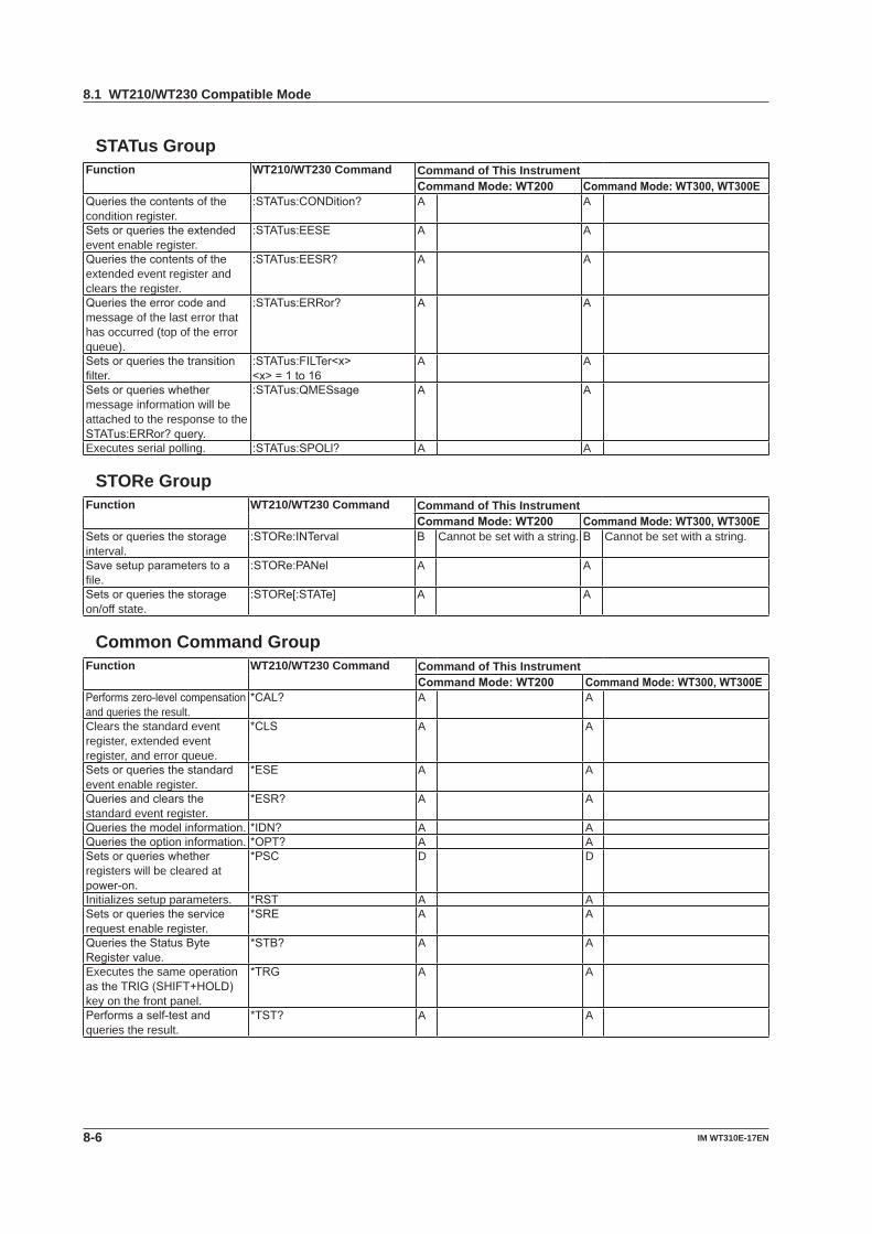
8-6 IM WT310E-17EN
STATus GroupFunction WT210/WT230 Command Command of This Instrument
CommandMode:WT200 CommandMode:WT300,WT300EQueriesthecontentsofthecondition register.
:STATus:CONDition? A A
Setsorqueriestheextendedevent enable register.
:STATus:EESE A A
Queriesthecontentsoftheextended event register and clears the register.
:STATus:EESR? A A
Queriestheerrorcodeandmessage of the last error that has occurred (top of the error queue).
:STATus:ERRor? A A
Setsorqueriesthetransitionfilter.
:STATus:FILTer<x><x>=1to16
A A
Setsorquerieswhethermessage information will be attached to the response to the STATus:ERRor?query.
:STATus:QMESsage A A
Executes serial polling. :STATus:SPOLl? A A
STORe GroupFunction WT210/WT230 Command Command of This Instrument
CommandMode:WT200 CommandMode:WT300,WT300ESetsorqueriesthestorageinterval.
:STORe:INTerval B Cannot be set with a string. B Cannot be set with a string.
Savesetupparameterstoafile.
:STORe:PANel A A
Setsorqueriesthestorageon/off state.
:STORe[:STATe] A A
Common Command GroupFunction WT210/WT230 Command Command of This Instrument
CommandMode:WT200 CommandMode:WT300,WT300EPerformszero-levelcompensationand queries the result.
*CAL? A A
Clears the standard event register, extended event register, and error queue.
*CLS A A
Setsorqueriesthestandardevent enable register.
*ESE A A
Queriesandclearsthestandard event register.
*ESR? A A
Queriesthemodelinformation. *IDN? A AQueriestheoptioninformation. *OPT? A ASetsorquerieswhetherregisters will be cleared at power-on.
*PSC D D
Initializes setup parameters. *RST A ASetsorqueriestheservicerequest enable register.
*SRE A A
QueriestheStatusByteRegistervalue.
*STB? A A
Executes the same operation astheTRIG(SHIFT+HOLD)key on the front panel.
*TRG A A
Performsaself-testandqueries the result.
*TST? A A
8.1 WT210/WT230 Compatible Mode

8-7IM WT310E-17EN
WT210/W
T230 Com
patible Com
mands
1
2
3
4
5
6
7
8
9
App
Index
Correspondence Table of WT210/WT230 Functions and Functions of This Instrument
Function expressions are shown below. For the WT210/WT230 compatible command mode, see the WT210/WT230 column.
WT210/WT230
This Instrument Notes
Normal measurementV UA IW PVA SVAR QPF LAMBdaDEGRee PHIVHZ FUAHZ FIWH WHWHP WHPWHM WHMAH AHAHP AHPAHM AHMVPK UPeak The larger of the absolute values UPPeak and UMPeakAPK IPeak The larger of the absolute values IPPeak and IMPeakTIME{} TIMEMATH MATH
UPPeak 1UMPeak 1IPPeak 1IMPeak 1PPPeak 1PMPeak 1
Harmonic measurementV UA IW PPF LAMBdaVHZ FUAHZ FIVTHD UTHDATHD ITHDVCON UHDFACON IHDFWCON PHDFVDEG PHIUADEG PHIIORDer ORDer
1 Newfunctionsonthisinstrument
8.1 WT210/WT230 Compatible Mode
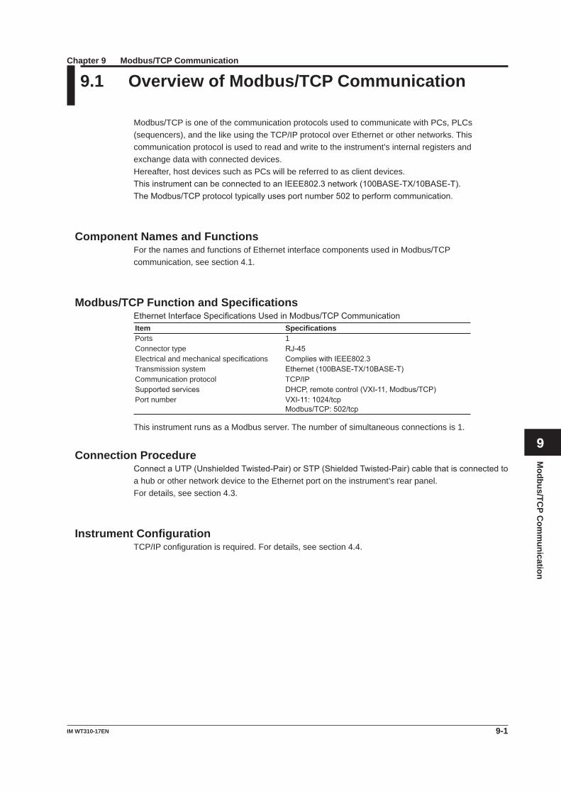
Modbus/TC
P Com
munication
9-1IM WT310-17EN
Chapter 9 Modbus/TCP Communication
1
2
3
4
5
6
7
8
9
App
Index
9.1 Overview of Modbus/TCP Communication
Modbus/TCP is one of the communication protocols used to communicate with PCs, PLCs (sequencers), and the like using the TCP/IP protocol over Ethernet or other networks. This communication protocol is used to read and write to the instrument’s internal registers and exchange data with connected devices.Hereafter, host devices such as PCs will be referred to as client devices.ThisinstrumentcanbeconnectedtoanIEEE802.3network(100BASE-TX/10BASE-T).TheModbus/TCPprotocoltypicallyusesportnumber502toperformcommunication.
Component Names and FunctionsFor the names and functions of Ethernet interface components used in Modbus/TCP communication, see section 4.1.
Modbus/TCP Function and SpecificationsEthernetInterfaceSpecificationsUsedinModbus/TCPCommunicationItem SpecificationsPorts 1Connector type RJ-45Electrical and mechanical specifications ComplieswithIEEE802.3Transmission system Ethernet(100BASE-TX/10BASE-T)Communication protocol TCP/IPSupportedservices DHCP,remotecontrol(VXI-11,Modbus/TCP)Port number VXI-11:1024/tcp
Modbus/TCP:502/tcp
This instrument runs as a Modbus server. The number of simultaneous connections is 1.
Connection ProcedureConnectaUTP(UnshieldedTwisted-Pair)orSTP(ShieldedTwisted-Pair)cablethatisconnectedtoa hub or other network device to the Ethernet port on the instrument’s rear panel.For details, see section 4.3.
Instrument ConfigurationTCP/IP configuration is required. For details, see section 4.4.
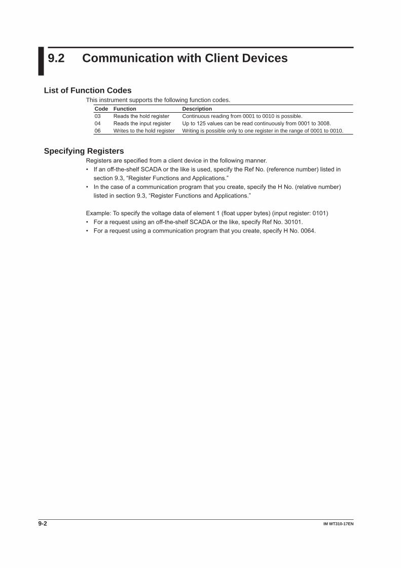
9-2 IM WT310-17EN
9.2 Communication with Client Devices
List of Function CodesThis instrument supports the following function codes.
Code Function Description03 Readstheholdregister Continuous reading from 0001 to 0010 is possible.04 Readstheinputregister Upto125valuescanbereadcontinuouslyfrom0001to3008.06 Writes to the hold register Writing is possible only to one register in the range of 0001 to 0010.
Specifying RegistersRegistersarespecifiedfromaclientdeviceinthefollowingmanner.• Ifanoff-the-shelfSCADAorthelikeisused,specifytheRefNo.(referencenumber)listedin
section9.3,“RegisterFunctionsandApplications.”• Inthecaseofacommunicationprogramthatyoucreate,specifytheHNo.(relativenumber)
listedinsection9.3,“RegisterFunctionsandApplications.”
Example:Tospecifythevoltagedataofelement1(floatupperbytes)(inputregister:0101)• Forarequestusinganoff-the-shelfSCADAorthelike,specifyRefNo.30101.• Forarequestusingacommunicationprogramthatyoucreate,specifyHNo.0064.
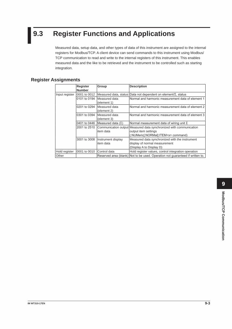
Modbus/TC
P Com
munication
9-3IM WT310-17EN
1
2
3
4
5
6
7
8
9
App
Index
9.3 Register Functions and Applications
Measured data, setup data, and other types of data of this instrument are assigned to the internal registers for Modbus/TCP. A client device can send commands to this instrument using Modbus/TCP communication to read and write to the internal registers of this instrument. This enables measured data and the like to be retrieved and the instrument to be controlled such as starting integration.
Register AssignmentsRegister Number
Group Description
Input register 0001 to 0012 Measured data, status Datanotdependentonelement/Σ,status0101to0194 Measured data
(element 1)Normalandharmonicmeasurementdataofelement1
0201to0294 Measured data(element 2)
Normalandharmonicmeasurementdataofelement2
0301to0394 Measured data(element 3)
Normalandharmonicmeasurementdataofelement3
0401to0446 Measureddata(Σ) NormalmeasurementdataofwiringunitΣ2001to2510 Communication output
item dataMeasured data synchronized with communication output item settings(:NUMeric[:NORMal]:ITEM<x>command)
3001to3008 Instrument display item data
Measured data synchronized with the instrument display of normal measurement(Display A to Display D)
Hold register 0001 to 0010 Control data Hold register values, control integration operationOther Reservedarea(blank) Nottobeused.Operationnotguaranteedifwrittento.
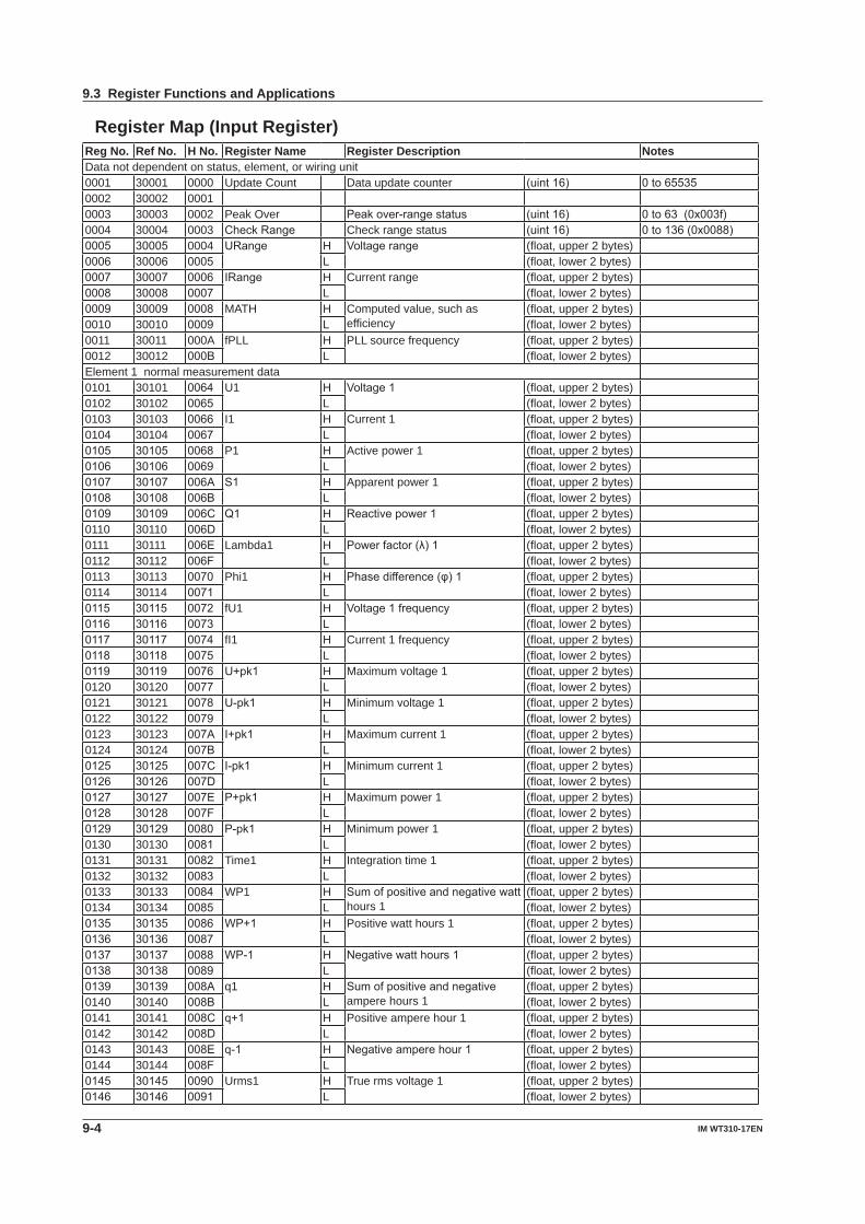
9-4 IM WT310-17EN
Register Map (Input Register)Reg No. Ref No. H No. Register Name Register Description NotesData not dependent on status, element, or wiring unit0001 30001 0000 Update Count Data update counter (uint16) 0to655350002 30002 00010003 30003 0002 Peak Over Peakover-rangestatus (uint16) 0to63(0x003f)0004 30004 0003 CheckRange Check range status (uint16) 0to136(0x0088)0005 30005 0004 URange H Voltagerange (float, upper 2 bytes)0006 30006 0005 L (float, lower 2 bytes)0007 30007 0006 IRange H Current range (float, upper 2 bytes)0008 30008 0007 L (float, lower 2 bytes)0009 30009 0008 MATH H Computed value, such as
efficiency(float, upper 2 bytes)
0010 30010 0009 L (float, lower 2 bytes)0011 30011 000A fPLL H PLL source frequency (float, upper 2 bytes)0012 30012 000B L (float, lower 2 bytes)Element 1 normal measurement data0101 30101 0064 U1 H Voltage1 (float, upper 2 bytes)0102 30102 0065 L (float, lower 2 bytes)0103 30103 0066 I1 H Current 1 (float, upper 2 bytes)0104 30104 0067 L (float, lower 2 bytes)0105 30105 0068 P1 H Active power 1 (float, upper 2 bytes)0106 30106 0069 L (float, lower 2 bytes)0107 30107 006A S1 H Apparent power 1 (float, upper 2 bytes)0108 30108 006B L (float, lower 2 bytes)0109 30109 006C Q1 H Reactivepower1 (float, upper 2 bytes)0110 30110 006D L (float, lower 2 bytes)0111 30111 006E Lambda1 H Powerfactor(λ)1 (float, upper 2 bytes)0112 30112 006F L (float, lower 2 bytes)0113 30113 0070 Phi1 H Phasedifference(φ)1 (float, upper 2 bytes)0114 30114 0071 L (float, lower 2 bytes)0115 30115 0072 fU1 H Voltage1frequency (float, upper 2 bytes)0116 30116 0073 L (float, lower 2 bytes)0117 30117 0074 fI1 H Current 1 frequency (float, upper 2 bytes)0118 30118 0075 L (float, lower 2 bytes)0119 30119 0076 U+pk1 H Maximum voltage 1 (float, upper 2 bytes)0120 30120 0077 L (float, lower 2 bytes)0121 30121 0078 U-pk1 H Minimum voltage 1 (float, upper 2 bytes)0122 30122 0079 L (float, lower 2 bytes)0123 30123 007A I+pk1 H Maximum current 1 (float, upper 2 bytes)0124 30124 007B L (float, lower 2 bytes)0125 30125 007C I-pk1 H Minimum current 1 (float, upper 2 bytes)0126 30126 007D L (float, lower 2 bytes)0127 30127 007E P+pk1 H Maximum power 1 (float, upper 2 bytes)0128 30128 007F L (float, lower 2 bytes)0129 30129 0080 P-pk1 H Minimum power 1 (float, upper 2 bytes)0130 30130 0081 L (float, lower 2 bytes)0131 30131 0082 Time1 H Integration time 1 (float, upper 2 bytes)0132 30132 0083 L (float, lower 2 bytes)0133 30133 0084 WP1 H Sumofpositiveandnegativewatt
hours 1(float, upper 2 bytes)
0134 30134 0085 L (float, lower 2 bytes)0135 30135 0086 WP+1 H Positive watt hours 1 (float, upper 2 bytes)0136 30136 0087 L (float, lower 2 bytes)0137 30137 0088 WP-1 H Negativewatthours1 (float, upper 2 bytes)0138 30138 0089 L (float, lower 2 bytes)0139 30139 008A q1 H Sumofpositiveandnegative
ampere hours 1(float, upper 2 bytes)
0140 30140 008B L (float, lower 2 bytes)0141 30141 008C q+1 H Positive ampere hour 1 (float, upper 2 bytes)0142 30142 008D L (float, lower 2 bytes)0143 30143 008E q-1 H Negativeamperehour1 (float, upper 2 bytes)0144 30144 008F L (float, lower 2 bytes)0145 30145 0090 Urms1 H True rms voltage 1 (float, upper 2 bytes)0146 30146 0091 L (float, lower 2 bytes)
9.3 Register Functions and Applications
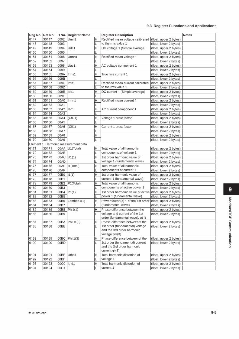
Modbus/TC
P Com
munication
9-5IM WT310-17EN
1
2
3
4
5
6
7
8
9
App
Index
Reg No. Ref No. H No. Register Name Register Description Notes0147 30147 0092 Umn1 H Rectifiedmeanvoltagecalibrated
to the rms value 1(float, upper 2 bytes)
0148 30148 0093 L (float, lower 2 bytes)0149 30149 0094 Udc1 H DCvoltage1(Simpleaverage) (float, upper 2 bytes)0150 30150 0095 L (float, lower 2 bytes)0151 30151 0096 Urmn1 H Rectifiedmeanvoltage1 (float, upper 2 bytes)0152 30152 0097 L (float, lower 2 bytes)0153 30153 0098 Uac1 H AC voltage component 1 (float, upper 2 bytes)0154 30154 0099 L (float, lower 2 bytes)0155 30155 009A Irms1 H True rms current 1 (float, upper 2 bytes)0156 30156 009B L (float, lower 2 bytes)0157 30157 009C Imn1 H Rectifiedmeancurrentcalibrated
to the rms value 1(float, upper 2 bytes)
0158 30158 009D L (float, lower 2 bytes)0159 30159 009E Idc1 H DCcurrent1(Simpleaverage) (float, upper 2 bytes)0160 30160 009F L (float, lower 2 bytes)0161 30161 00A0 Irmn1 H Rectifiedmeancurrent1 (float, upper 2 bytes)0162 30162 00A1 L (float, lower 2 bytes)0163 30163 00A2 Iac1 H AC current component 1 (float, upper 2 bytes)0164 30164 00A3 L (float, lower 2 bytes)0165 30165 00A4 (CfU1) H Voltage1crestfactor (float, upper 2 bytes)0166 30166 00A5 L (float, lower 2 bytes)0167 30167 00A6 (CfI1) H Current 1 crest factor (float, upper 2 bytes)0168 30168 00A7 L (float, lower 2 bytes)0169 30169 00A8 H (float, upper 2 bytes)0170 30170 00A9 L (float, lower 2 bytes)Element 1 Harmonic measurement data0171 30171 00AA U1(Total) H Total value of all harmonic
components of voltage 1(float, upper 2 bytes)
0172 30172 00AB L (float, lower 2 bytes)0173 30173 00AC U1(1) H 1st order harmonic value of
voltage 1 (fundamental wave)(float, upper 2 bytes)
0174 30174 00AD L (float, lower 2 bytes)0175 30175 00AE I1(Total) H Total value of all harmonic
components of current 1(float, upper 2 bytes)
0176 30176 00AF L (float, lower 2 bytes)0177 30177 00B0 I1(1) H 1st order harmonic value of
current 1 (fundamental wave)(float, upper 2 bytes)
0178 30178 00B1 L (float, lower 2 bytes)0179 30179 00B2 P1(Total) H Total value of all harmonic
components of active power 1(float, upper 2 bytes)
0180 30180 00B3 L (float, lower 2 bytes)0181 30181 00B4 P1(1) H 1st order harmonic value of active
power 1 (fundamental wave)(float, upper 2 bytes)
0182 30182 00B5 L (float, lower 2 bytes)0183 30183 00B6 Lambda1(1) H Powerfactor(λ)1ofthe1storder
(fundamental wave)(float, upper 2 bytes)
0184 30184 00B7 L (float, lower 2 bytes)0185 30185 00B8 Phi1(1) H Phase difference between the
voltage and current of the 1st order(fundamentalwave),φ(1)
(float, upper 2 bytes)0186 30186 00B9 L (float, lower 2 bytes)
0187 30187 00BA PhiU1(3) H Phase difference betweenof the 1st order (fundamental) voltage and the 3rd order harmonic voltageφU(3)
(float, upper 2 bytes)0188 30188 00BB L (float, lower 2 bytes)
0189 30189 00BC PhiI1(3) H Phase difference betweenof the 1st order (fundamental) current and the 3rd order harmonic currentφI(3)
(float, upper 2 bytes)0190 30190 00BD L (float, lower 2 bytes)
0191 30191 00BE Uthd1 H Total harmonic distortion of voltage 1
(float, upper 2 bytes)0192 30192 00BF L (float, lower 2 bytes)0193 30193 00C0 Ithd1 H Total harmonic distortion of
current 1(float, upper 2 bytes)
0194 30194 00C1 L (float, lower 2 bytes)
9.3 Register Functions and Applications
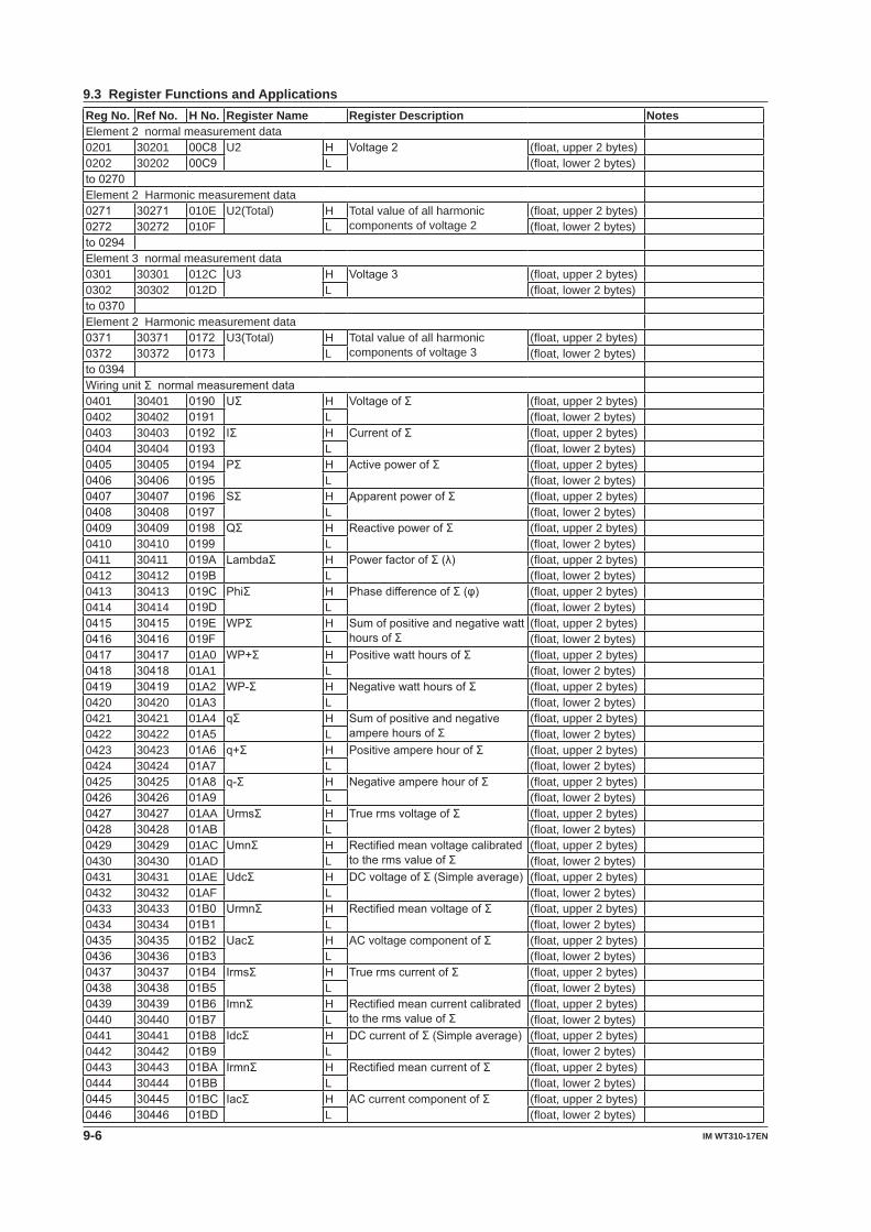
9-6 IM WT310-17EN
Reg No. Ref No. H No. Register Name Register Description NotesElement 2 normal measurement data0201 30201 00C8 U2 H Voltage2 (float, upper 2 bytes)0202 30202 00C9 L (float, lower 2 bytes)to0270Element 2 Harmonic measurement data0271 30271 010E U2(Total) H Total value of all harmonic
components of voltage 2(float, upper 2 bytes)
0272 30272 010F L (float, lower 2 bytes)to0294Element 3 normal measurement data0301 30301 012C U3 H Voltage3 (float, upper 2 bytes)0302 30302 012D L (float, lower 2 bytes)to0370Element 2 Harmonic measurement data0371 30371 0172 U3(Total) H Total value of all harmonic
components of voltage 3(float, upper 2 bytes)
0372 30372 0173 L (float, lower 2 bytes)to0394WiringunitΣnormalmeasurementdata0401 30401 0190 UΣ H VoltageofΣ (float, upper 2 bytes)0402 30402 0191 L (float, lower 2 bytes)0403 30403 0192 IΣ H CurrentofΣ (float, upper 2 bytes)0404 30404 0193 L (float, lower 2 bytes)0405 30405 0194 PΣ H ActivepowerofΣ (float, upper 2 bytes)0406 30406 0195 L (float, lower 2 bytes)0407 30407 0196 SΣ H ApparentpowerofΣ (float, upper 2 bytes)0408 30408 0197 L (float, lower 2 bytes)0409 30409 0198 QΣ H ReactivepowerofΣ (float, upper 2 bytes)0410 30410 0199 L (float, lower 2 bytes)0411 30411 019A LambdaΣ H PowerfactorofΣ(λ) (float, upper 2 bytes)0412 30412 019B L (float, lower 2 bytes)0413 30413 019C PhiΣ H PhasedifferenceofΣ(φ) (float, upper 2 bytes)0414 30414 019D L (float, lower 2 bytes)0415 30415 019E WPΣ H Sumofpositiveandnegativewatt
hoursofΣ(float, upper 2 bytes)
0416 30416 019F L (float, lower 2 bytes)0417 30417 01A0 WP+Σ H PositivewatthoursofΣ (float, upper 2 bytes)0418 30418 01A1 L (float, lower 2 bytes)0419 30419 01A2 WP-Σ H NegativewatthoursofΣ (float, upper 2 bytes)0420 30420 01A3 L (float, lower 2 bytes)0421 30421 01A4 qΣ H Sumofpositiveandnegative
amperehoursofΣ(float, upper 2 bytes)
0422 30422 01A5 L (float, lower 2 bytes)0423 30423 01A6 q+Σ H PositiveamperehourofΣ (float, upper 2 bytes)0424 30424 01A7 L (float, lower 2 bytes)0425 30425 01A8 q-Σ H NegativeamperehourofΣ (float, upper 2 bytes)0426 30426 01A9 L (float, lower 2 bytes)0427 30427 01AA UrmsΣ H TruermsvoltageofΣ (float, upper 2 bytes)0428 30428 01AB L (float, lower 2 bytes)0429 30429 01AC UmnΣ H Rectifiedmeanvoltagecalibrated
tothermsvalueofΣ(float, upper 2 bytes)
0430 30430 01AD L (float, lower 2 bytes)0431 30431 01AE UdcΣ H DCvoltageofΣ(Simpleaverage) (float, upper 2 bytes)0432 30432 01AF L (float, lower 2 bytes)0433 30433 01B0 UrmnΣ H RectifiedmeanvoltageofΣ (float, upper 2 bytes)0434 30434 01B1 L (float, lower 2 bytes)0435 30435 01B2 UacΣ H ACvoltagecomponentofΣ (float, upper 2 bytes)0436 30436 01B3 L (float, lower 2 bytes)0437 30437 01B4 IrmsΣ H TruermscurrentofΣ (float, upper 2 bytes)0438 30438 01B5 L (float, lower 2 bytes)0439 30439 01B6 ImnΣ H Rectifiedmeancurrentcalibrated
tothermsvalueofΣ(float, upper 2 bytes)
0440 30440 01B7 L (float, lower 2 bytes)0441 30441 01B8 IdcΣ H DCcurrentofΣ(Simpleaverage) (float, upper 2 bytes)0442 30442 01B9 L (float, lower 2 bytes)0443 30443 01BA IrmnΣ H RectifiedmeancurrentofΣ (float, upper 2 bytes)0444 30444 01BB L (float, lower 2 bytes)0445 30445 01BC IacΣ H ACcurrentcomponentofΣ (float, upper 2 bytes)0446 30446 01BD L (float, lower 2 bytes)
9.3 Register Functions and Applications
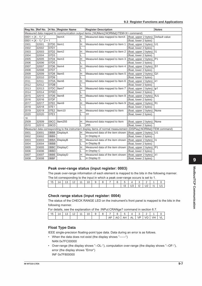
Modbus/TC
P Com
munication
9-7IM WT310-17EN
1
2
3
4
5
6
7
8
9
App
Index
Reg No. Ref No. H No. Register Name Register Description NotesMeasureddatamappedtocommunicationoutputitems(:NUMeric[:NORMal]:ITEM<X>command)0001+(X-1)*2 ItemX H Measured data mapped to ItemX (float, upper 2 bytes) Default value0001+(X-1)*2+1 L (float, lower 2 bytes)2001 32001 07D0 Item1 H Measured data mapped to Item 1 (float, upper 2 bytes) U12002 32002 07D1 L (float, lower 2 bytes)2003 32003 07D2 Item2 H Measured data mapped to Item 2 (float, upper 2 bytes) I12004 32004 07D3 L (float, lower 2 bytes)2005 32005 07D4 Item3 H Measured data mapped to Item 3 (float, upper 2 bytes) P12006 32006 07D5 L (float, lower 2 bytes)2007 32007 07D6 Item4 H Measured data mapped to Item 4 (float, upper 2 bytes) S12008 32008 07D7 L (float, lower 2 bytes)2009 32009 07D8 Item5 H MeasureddatamappedtoItem5 (float, upper 2 bytes) Q12010 32010 07D9 L (float, lower 2 bytes)2011 32011 07DA Item6 H MeasureddatamappedtoItem6 (float, upper 2 bytes) λ12012 32012 07DB L (float, lower 2 bytes)2013 32013 07DC Item7 H MeasureddatamappedtoItem7 (float, upper 2 bytes) φ12014 32014 07DD L (float, lower 2 bytes)2015 32015 07DE Item8 H MeasureddatamappedtoItem8 (float, upper 2 bytes) fU12016 32016 07DF L (float, lower 2 bytes)2017 32017 07E0 Item9 H MeasureddatamappedtoItem9 (float, upper 2 bytes) fI12018 32018 07E1 L (float, lower 2 bytes)2019 32019 07E2 Item10 H Measured data mapped to Item
10(float, upper 2 bytes) None
2020 32020 07E3 L (float, lower 2 bytes) to 2509 32509 09CC Item255 H Measured data mapped to Item
255(float, upper 2 bytes) None
2510 32510 09CD L (float, lower 2 bytes)Measureddatacorrespondingtotheinstrumentdisplayitemsofnormalmeasurement(DISPlay[:NORMal]:ITEMcommand)3001 33001 0BB8 DisplayA H Measured data of the item shown
in Display A(float, upper 2 bytes) U1
3002 33002 0BB9 L (float, lower 2 bytes)3003 33003 0BBA DisplayB H Measured data of the item shown
inDisplayB(float, upper 2 bytes) I1
3004 33004 0BBB L (float, lower 2 bytes)3005 33005 0BBC DisplayC H Measured data of the item shown
in Display C(float, upper 2 bytes) P1
3006 33006 0BBD L (float, lower 2 bytes)3007 33007 0BBE DisplayD H Measured data of the item shown
in Display D(float, upper 2 bytes) λ1
3008 33008 0BBF L (float, lower 2 bytes)
Peakover-rangestatus(inputregister:0003)Thepeakover-rangeinformationofeachelementismappedtothebitsinthefollowingmanner.Thebitcorrespondingtotheinputinwhichapeakover-rangeoccursissetto1.15 14 13 12 11 10 9 8 7 6 5 4 3 2 1 0
I3 U3 I2 U2 I1 U1
Checkrangestatus(inputregister:0004)ThestatusoftheCHECKRANGELEDontheinstrument’sfrontpanelismappedtothebitsinthefollowing manner.Fordetails,seetheexplanationofthe:INPut:CRANge?commandinsection6.7.15 14 13 12 11 10 9 8 7 6 5 4 3 2 1 0
AP AO AH AL VP VO VH VL
Float Type DataIEEEsingle-precisionfloating-pointtypedata.Dataduringanerrorisasfollows.• Whenthedatadoesnotexist(thedisplayshows”------“) NAN0x7FC00000• Over-range(thedisplayshows”--OL-“),computationover-range(thedisplayshows”--OF-“),
error(thedisplayshows”Error“) INF0x7F800000
9.3 Register Functions and Applications
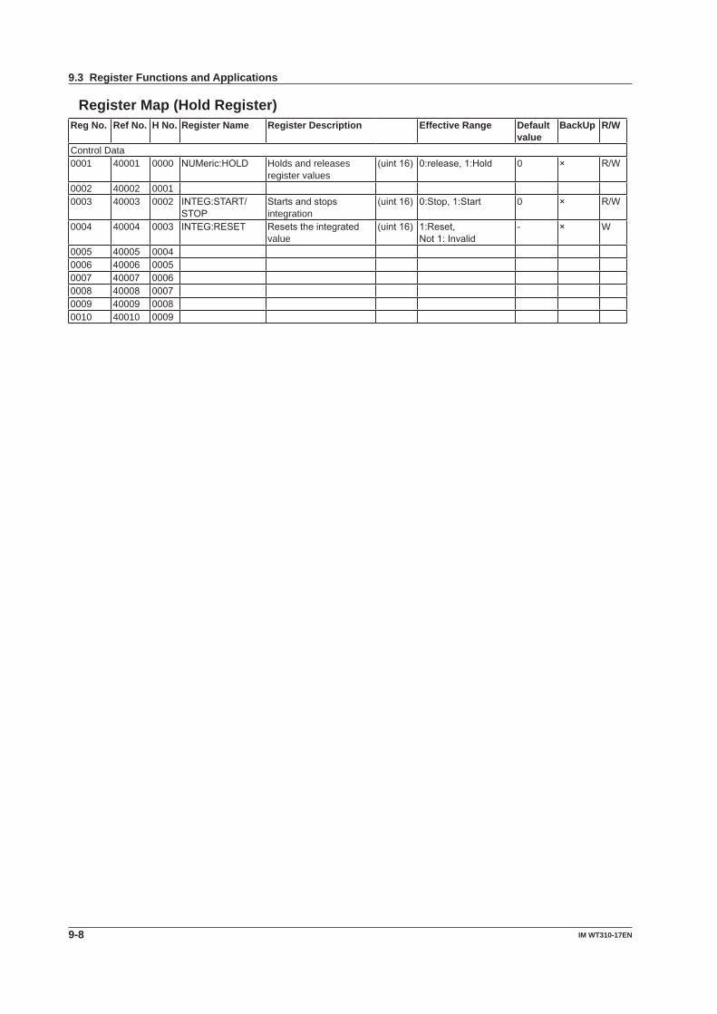
9-8 IM WT310-17EN
Register Map (Hold Register)Reg No. Ref No. H No. Register Name Register Description Effective Range Default
valueBackUp R/W
Control Data0001 40001 0000 NUMeric:HOLD Holds and releases
register values(uint16) 0:release,1:Hold 0 × R/W
0002 40002 00010003 40003 0002 INTEG:START/
STOPStartsandstopsintegration
(uint16) 0:Stop,1:Start 0 × R/W
0004 40004 0003 INTEG:RESET Resetstheintegratedvalue
(uint16) 1:Reset,Not1:Invalid
- × W
0005 40005 00040006 40006 00050007 40007 00060008 40008 00070009 40009 00080010 40010 0009
9.3 Register Functions and Applications
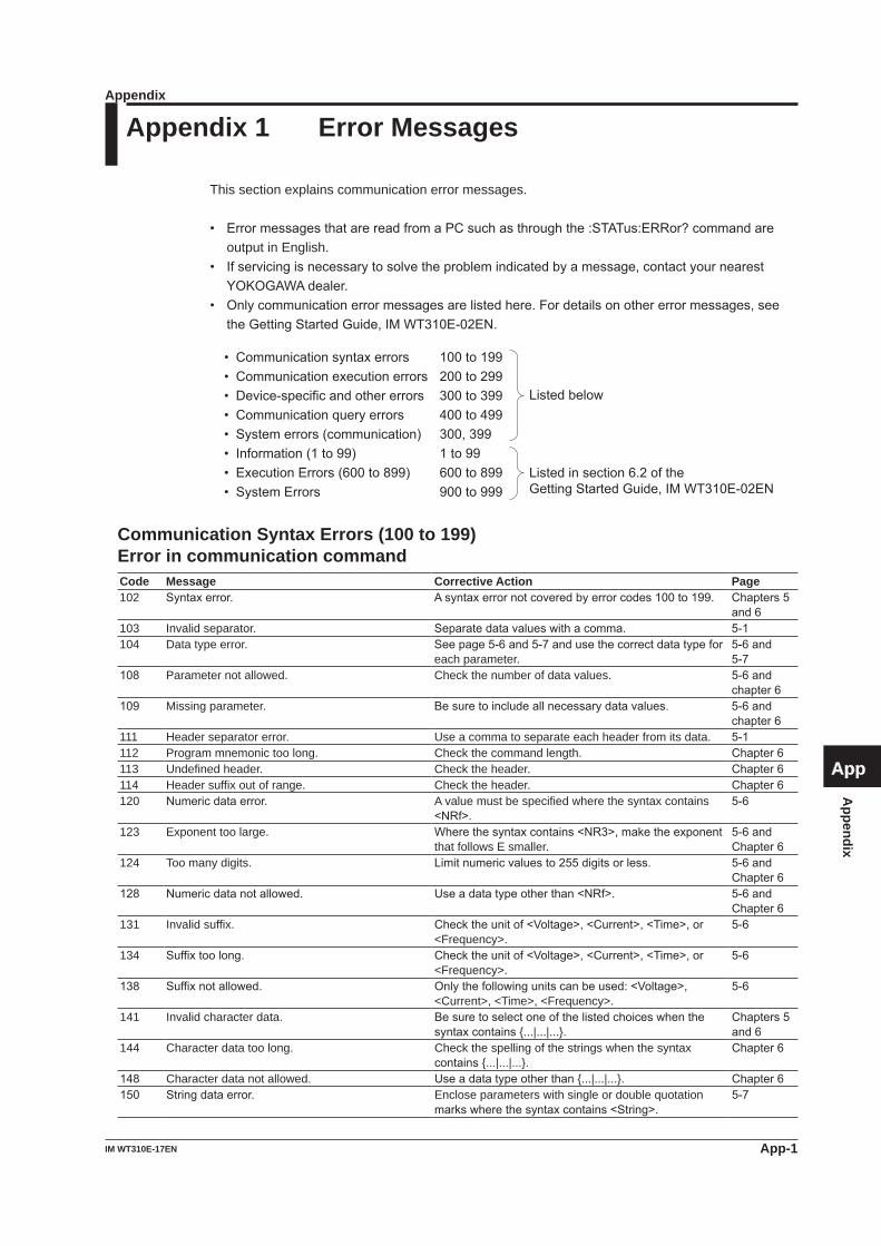
Appendix
App-1IM WT310E-17EN
1
2
3
4
5
6
7
8
9
App
Index
Appendix 1 Error Messages
This section explains communication error messages.
• ErrormessagesthatarereadfromaPCsuchasthroughthe:STATus:ERRor?commandareoutput in English.
• Ifservicingisnecessarytosolvetheproblemindicatedbyamessage,contactyournearestYOKOGAWAdealer.
• Onlycommunicationerrormessagesarelistedhere.Fordetailsonothererrormessages,seetheGettingStartedGuide,IMWT310E-02EN.
• Communication syntax errors • Communication execution errors • Device-specific and other errors • Communication query errors • System errors (communication) • Information (1 to 99) • Execution Errors (600 to 899) • System Errors
100 to 199 200 to 299 300 to 399 400 to 499 300, 399 1 to 99 600 to 899 900 to 999
Listed below
Listed in section 6.2 of the Getting Started Guide, IM WT310E-02EN
Communication Syntax Errors (100 to 199)Error in communication commandCode Message Corrective Action Page102 Syntaxerror. Asyntaxerrornotcoveredbyerrorcodes100to199. Chapters5
and6103 Invalid separator. Separatedatavalueswithacomma. 5-1104 Data type error. Seepage5-6and5-7andusethecorrectdatatypefor
each parameter.5-6and5-7
108 Parameter not allowed. Check the number of data values. 5-6andchapter6
109 Missing parameter. Besuretoincludeallnecessarydatavalues. 5-6andchapter6
111 Header separator error. Use a comma to separate each header from its data. 5-1112 Program mnemonic too long. Check the command length. Chapter6113 Undefined header. Check the header. Chapter6114 Header suffix out of range. Check the header. Chapter6120 Numericdataerror. A value must be specified where the syntax contains
<NRf>.5-6
123 Exponent too large. Wherethesyntaxcontains<NR3>,maketheexponentthat follows E smaller.
5-6andChapter6
124 Too many digits. Limitnumericvaluesto255digitsorless. 5-6andChapter6
128 Numericdatanotallowed. Useadatatypeotherthan<NRf>. 5-6andChapter6
131 Invalid suffix. Checktheunitof<Voltage>,<Current>,<Time>,or<Frequency>.
5-6
134 Suffixtoolong. Checktheunitof<Voltage>,<Current>,<Time>,or<Frequency>.
5-6
138 Suffixnotallowed. Onlythefollowingunitscanbeused:<Voltage>,<Current>, <Time>, <Frequency>.
5-6
141 Invalid character data. Besuretoselectoneofthelistedchoiceswhenthesyntaxcontains{...|...|...}.
Chapters5and6
144 Character data too long. Check the spelling of the strings when the syntax contains{...|...|...}.
Chapter6
148 Character data not allowed. Useadatatypeotherthan{...|...|...}. Chapter6150 Stringdataerror. Enclose parameters with single or double quotation
markswherethesyntaxcontains<String>.5-7
Appendix
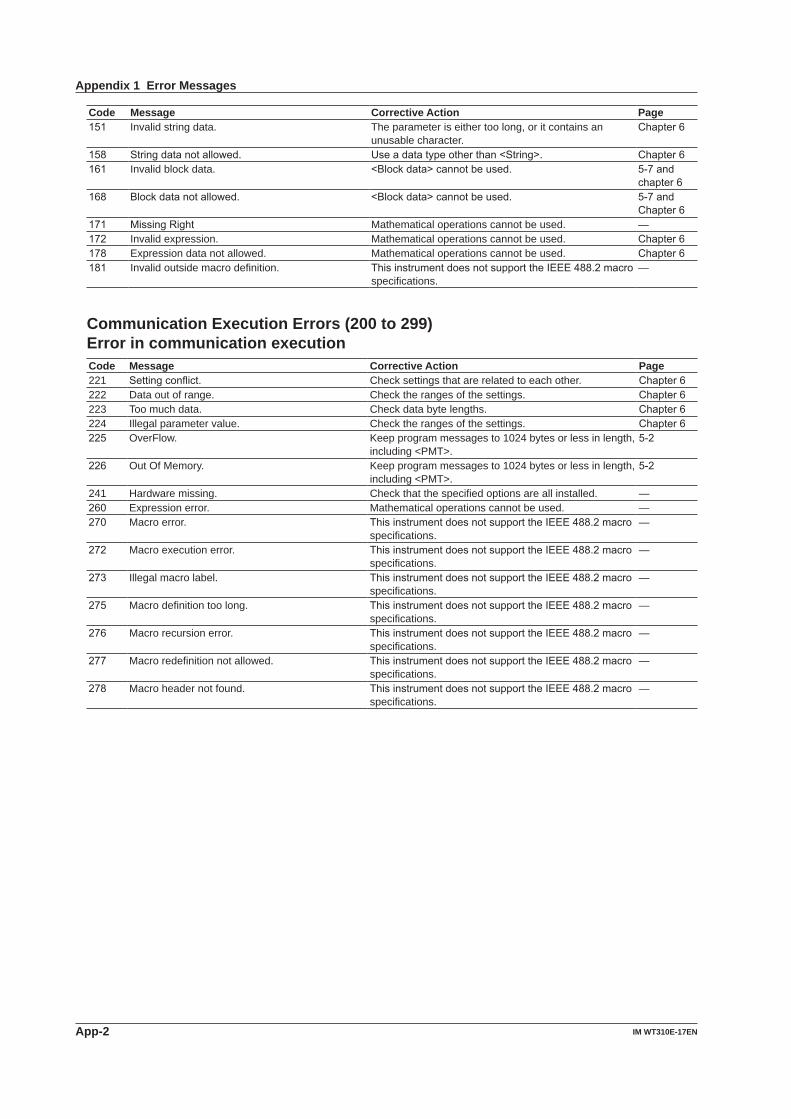
App-2 IM WT310E-17EN
Code Message Corrective Action Page151 Invalid string data. The parameter is either too long, or it contains an
unusable character.Chapter6
158 Stringdatanotallowed. Useadatatypeotherthan<String>. Chapter6161 Invalid block data. <Blockdata>cannotbeused. 5-7and
chapter6168 Blockdatanotallowed. <Blockdata>cannotbeused. 5-7and
Chapter6171 MissingRight Mathematical operations cannot be used. —172 Invalid expression. Mathematical operations cannot be used. Chapter6178 Expression data not allowed. Mathematical operations cannot be used. Chapter6181 Invalid outside macro definition. ThisinstrumentdoesnotsupporttheIEEE488.2macro
specifications.—
Communication Execution Errors (200 to 299)Error in communication executionCode Message Corrective Action Page221 Settingconflict. Check settings that are related to each other. Chapter6222 Data out of range. Check the ranges of the settings. Chapter6223 Too much data. Check data byte lengths. Chapter6224 Illegal parameter value. Check the ranges of the settings. Chapter6225 OverFlow. Keep program messages to 1024 bytes or less in length,
including <PMT>.5-2
226 Out Of Memory. Keep program messages to 1024 bytes or less in length, including <PMT>.
5-2
241 Hardware missing. Check that the specified options are all installed. —260 Expression error. Mathematical operations cannot be used. —270 Macro error. ThisinstrumentdoesnotsupporttheIEEE488.2macro
specifications.—
272 Macro execution error. ThisinstrumentdoesnotsupporttheIEEE488.2macrospecifications.
—
273 Illegal macro label. ThisinstrumentdoesnotsupporttheIEEE488.2macrospecifications.
—
275 Macro definition too long. ThisinstrumentdoesnotsupporttheIEEE488.2macrospecifications.
—
276 Macro recursion error. ThisinstrumentdoesnotsupporttheIEEE488.2macrospecifications.
—
277 Macro redefinition not allowed. ThisinstrumentdoesnotsupporttheIEEE488.2macrospecifications.
—
278 Macro header not found. ThisinstrumentdoesnotsupporttheIEEE488.2macrospecifications.
—
Appendix 1 Error Messages
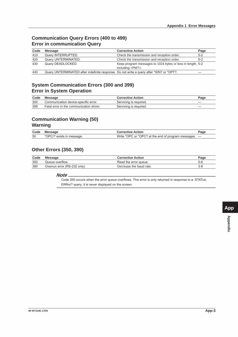
Appendix
App-3IM WT310E-17EN
1
2
3
4
5
6
7
8
9
App
Index
Communication Query Errors (400 to 499)Error in communication QueryCode Message Corrective Action Page410 QueryINTERRUPTED. Check the transmission and reception order. 5-2420 QueryUNTERMINATED. Check the transmission and reception order. 5-2430 QueryDEADLOCKED. Keep program messages to 1024 bytes or less in length,
including <PMT>.5-2
440 QueryUNTERMINATEDafterindefiniteresponse. Donotwriteaqueryafter*IDN?or*OPT?. —
System Communication Errors (300 and 399)Error in System OperationCode Message Corrective Action Page300 Communicationdevice-specificerror. Servicingisrequired. —399 Fatal error in the communication driver. Servicingisrequired. —
Communication Warning (50)WarningCode Message Corrective Action Page50 *OPC/?existsinmessage. Write*OPCor*OPC?attheendofprogrammessages. —
Other Errors (350, 390)Code Message Corrective Action Page350 Queueoverflow. Readtheerrorqueue. 5-6390 Overrunerror(RS-232only) Decrease the baud rate. 3-8
NoteCode350occurswhentheerrorqueueoverflows.Thiserrorisonlyreturnedinresponsetoa:STATus:ERRor?query;itisneverdisplayedonthescreen.
Appendix 1 Error Messages
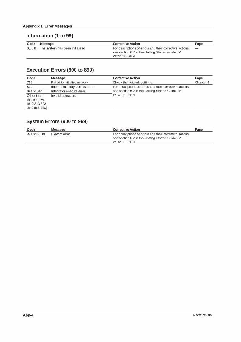
App-4 IM WT310E-17EN
Information (1 to 99)Code Message Corrective Action Page3,80,87 The system has been initialized For descriptions of errors and their corrective actions,
seesection6.2intheGettingStartedGuide,IMWT310E-02EN.
—
Execution Errors (600 to 899)Code Message Corrective Action Page759 Failed to initialize network. Check the network settings. Chapter 4832 Internal memory access error. For descriptions of errors and their corrective actions,
seesection6.2intheGettingStartedGuide,IMWT310E-02EN.
—841 to 847 Integrator execute error.Other than those above.(812,813,823,840,865,886)
Invalid operation.
System Errors (900 to 999)Code Message Corrective Action Page901,915,919 Systemerror. For descriptions of errors and their corrective actions,
seesection6.2intheGettingStartedGuide,IMWT310E-02EN.
—
Appendix 1 Error Messages

Appendix
App-5IM WT310E-17EN
1
2
3
4
5
6
7
8
9
App
Index
Appendix 2 About the IEEE 488.2-1992 Standard
TheGP-IB interfaceof this instrumentconformsto the IEEE488.2-1992standard.Thisstandardspecifies that thefollowing 23 items be stated in the document. This section describes these items.
(1) Of the IEEE 488.1 interface functions, the subsets that are supported
See section2.2, “GP-IB InterfaceFeaturesandSpecifications.”
(2) The operation of the device when it is assigned an address outside the 0 to 30 range.
The address of this instrument cannot be set to an address outside the 0 to 30 range.
(3) Reaction of the device when the user changes the address
The address change is detected when the user presses INTERFACEand changes theaddressontheGPibmenu.Thenewaddressisvaliduntilthe next time it is changed.
(4) Device settings at power-up. The commands that can be used at power-up.
As a basic rule, the previous settings (the settings that were in use when this instrument was turned off) are used.
There are no limitations on the commands that canbeusedatpower-up.
(5) Message exchange options (a) Input buffer size 1024 bytes. (b) Queries that return multiple response
messages See the example of the commands given in
chapter6. (c) Queries that create response data when
the command syntax is being analyzed All queries create response data when the
command syntax is analyzed. (d) Queries that create response data during
reception There are no queries of which the response data
are created upon receiving a send request from the controller.
(e) Commands that have parameters that restrict one another
See the example of the commands given inchapter6.
(6) Items that are included in the functional or composite header elements constituting a command
Seechapters5and6.(7) Buffer sizes that affect block data
transmission When block data is being transmitted, the output
queue is expanded to match the size of the data that is being transmitted.
(8) A list of program data elements that can be used in equations and their nesting limitations
Equations cannot be used.(9) Syntax of the responses to queries See the example of the commands given in
chapter6.(10) Communication between devices that do not
follow the response syntax Notsupported.(11) Size of the response data block 0to24576bytes(12) A list of supported common commands Seesection6.17,“CommonCommandGroup.”(13) Device condition after a successful calibration The device will be performing measurements.(14) The maximum length of block data that can be
used for the *DDT trigger macro definition Notsupported.(15) The maximum length of the macro label for
defining macros, the maximum length of block data that can be used for the macro definition, and the process when recursion is used in macro definitions
Macro functions are not supported.(16) Reply to the *IDN? query Seesection6.17,“CommonCommandGroup.”(17) Size of storage area for protected user data
for PUD and *PUD? *PUDand*PUD?arenotsupported.(18) The length of the *RDT and *RDT? resource
names *RDTand*RDT?arenotsupported.(19) The change in the status due to *RST, *LRN?,
*RCL, *SAV, and *RST Seesection6.17,“CommonCommandGroup.” *LRN?, *RCL, and *SAV These common commands are not supported.(20) The extent of the self-test using the *TST?
command Seesection6.17,“CommonCommandGroup.”(21) The structure of the extended return status Seechapter7.(22) Whether each command is processed in an
overlapped manner or sequentially See section 5.5, “Synchronizationwith the
Controller”andchapter6.(23) The description of the execution of each
command Seetheexplanationsofeachcommand’sfunction
inchapter6andtheUser’sManual,IMWT310E-01EN.
Index-1IM WT310E-17EN
Index
1
2
3
4
5
6
7
8
9
App
Index
Index
A Page
abbreviated form................................................................... 5-5address ................................................................................. 2-2addressable mode ................................................................ 2-2auto range ................................................................. 6-12,6-13averaging ............................................................................ 6-18
B Page
baud rate .............................................................................. 3-8block data ............................................................................. 5-7boolean ................................................................................. 5-7
C Page
CAL ..................................................................................... 6-34character data....................................................................... 5-7check range status ............................................................. 6-15command ............................................................................ 6-33command mode .................................................................... 8-1commands ............................................................................ 5-3common command header ................................................... 5-3computation function .......................................................... 6-17condition register ................................................................ 6-31crest factor .......................................................................... 6-12CS-RS .................................................................................. 3-7CT ratio ............................................................................... 6-14current .................................................................................. 5-6current range ...................................................................... 6-13
D Page
D/A output ............................................................................. 6-5D/A output items ................................................................... 6-5Data ...................................................................................... 5-6data format ........................................................................... 3-8data update interval ............................................................ 6-29DCL (Device Clear) .............................................................. 2-7deadlock ............................................................................... 5-2default gateway .................................................................... 4-5DHCP ................................................................................... 4-5display .................................................................................. 6-8display resolution ................................................................ 6-33driver......................................................................................... ii
E Page
Error Messages ................................................................ App-1error queue ........................................................................... 7-6Ethernet interface ................................................................. 4-2extended event register ............................................... 6-31,7-5external event enable register ............................................ 6-31external sensor conversion ratio......................................... 6-14external sensor range ......................................................... 6-13
F Page
firmware .............................................................................. 6-33frequency filter .................................................................... 6-15front panel........................................................1-1,2-1,3-1,4-1function selection ................................................................ 6-24
G Page
GET(GroupExecuteTrigger) ............................................... 2-7GP-IBaddress ...................................................................... 2-6GP-IBboard.......................................................................... 2-4GP-IBInterface ..................................................................... 2-2Group.................................................................................... 5-3GTL(GoToLocal) ................................................................ 2-7
H Page
handshaking ......................................................................... 3-6harmonic measurement ...................................................... 6-10harmonic order ................................................................... 6-10hold ......................................................................................6-11
I Page
IFC (Interface Clear) ............................................................. 2-7initialization ......................................................................... 6-35input filter ............................................................................ 6-15integration ........................................................................... 6-16integration mode ................................................................. 6-16integration, reset ................................................................. 6-16integration, start .................................................................. 6-16integration, stop .................................................................. 6-16integration timer .................................................................. 6-16IP address ............................................................................ 4-5
K Page
key lock............................................................................... 6-33
L Page
library ........................................................................................ iiline filter .............................................................................. 6-15LLO (Local Lockout) ............................................................. 2-7load ..................................................................................... 6-30LOAD .................................................................................. 6-30local lockout .......................................................................... 6-7
M Page
MAC address ...................................................................... 6-33MAX hold ............................................................................ 6-18measurement mode............................................................ 6-12messages ............................................................................. 5-1Modbus/TCP ......................................................................... 9-1model ......................................................................... 6-33,6-34model code ......................................................................... 6-33
N Page
NRf ....................................................................................... 5-7numeric data ....................................................................... 6-19numeric data format............................................................ 6-25
O Page
OFF-OFF .............................................................................. 3-6option .................................................................................. 6-35output queue......................................................................... 7-6overlap command ................................................................. 5-8
Index-2 IM WT310E-17EN
Index
P Page
peakover-range ................................................................. 6-15PLL source ......................................................................... 6-10power factor ........................................................................ 6-14preset.................................................................................. 6-26program messages ............................................................... 5-1
Q Page
Query .................................................................................... 5-1
R Page
range configuration ............................................................. 6-14range skip ........................................................................... 6-14rear panel ........................................................1-1,2-1,3-1,4-1Register ................................................................................ 5-7remote .................................................................................. 6-7remote and local modes, switching .................1-2,2-3,3-2,4-2REN(RemoteEnable) .......................................................... 2-7response ............................................................................... 5-5response messages ............................................................. 5-1responses without headers................................................... 5-5RS-232interface................................................................... 3-2
S Page
SamplePrograms ..................................................................... iiSAVE .................................................................................. 6-30scaling ................................................................................ 6-14SDC(SelectedDeviceClear) ............................................... 2-7self-test ............................................................................... 6-36serial number ...................................................................... 6-33serial polling........................................................................ 6-31service request enable register .......................................... 6-35setup parameters................................................................ 6-32single measurement ........................................................... 6-35SPD(SerialPollDisable)...................................................... 2-7SPE(SerialPollEnable)....................................................... 2-7standard event enable register ........................................... 6-34standard event register ................................................ 6-34,7-4status byte ............................................................................ 7-3status byte register ............................................................. 6-35status report........................................................................ 6-31status reports ........................................................................ 7-1storage................................................................................ 6-32storage interval ................................................................... 6-32string data ............................................................................. 5-7subnet mask ......................................................................... 4-5suffix ................................................................................... 6-33suffix code .......................................................................... 6-33synchronization source ....................................................... 6-14
T Page
TCP/IP .................................................................................. 4-5terminator ............................................................................. 3-8time ....................................................................................... 5-6TMCTL ...................................................................................... iitransition filter .............................................................. 6-31,7-5
U Page
upper-levelquery .................................................................. 5-4USBcable............................................................................. 1-3USBhub ............................................................................... 1-3USBinterface ....................................................................... 1-2USBTMC ............................................................................. 1-4
V Page
version ................................................................................ 6-33voltage .................................................................................. 5-6voltage range ...................................................................... 6-12VTratio ............................................................................... 6-14
W Page
wiring system ...................................................................... 6-12WT210/W230........................................................................ 8-1WTViewerFreePlus ................................................................... ii
X Page
XON-XON ............................................................................. 3-6
Z Page
zero-levelcompensation..................................................... 6-34