Embed Size (px)
Citation preview


LIMITED COMPANY
AEROSPOOL PRIEVIDZA
Airfield Prievidza
971 03 PRIEVIDZA
Slovak Republic
Fax: +421 46 51 83 250
Tel.: +421 46 51 83 200
www.aerospool.sk
F L I G H T M A N U A L
FOR THE LIGHT SPORT AIRCRAFT
WT9 Dynamic LSA Speed S
MTOW 600kg
Type: WT9 Dynamic LSA
Model: Speed S
Serial No: DY - 391/2010 LSA
Registration: OK-WOW
Date of Issue: 14.06.2011
Signature:
Authority:
Stamp:
Original date of approval:
This airplane is to be operated in compliance with information and limitations contained
herein.

WT9 Dynamic LSA Speed S FLIGHT MANUAL Section 0 Page 0-1
0.1. RECORD OF REVISION
Any revision of the present manual, except actual weight data, must be recorded in the
following table and in case of approved Sections endorsed by the responsible
airworthiness authority.
The new or amended text in the revised pages will be indicated by a black vertical line in
the right hand margin, and the Revision No. and the date will be shown on the bottom
left side of the page.
Rev. No.
Affected Section
Affected Pages
Date of
issue Approval Date Date
inserted Signature
1 ALL ALL 28.10.2010
2 0 1, 2, 3 14.06.2011
2 1 3 14.06.2011
2 2 8 14.06.2011
2 3 5, 6 14.06.2011
2 4 5, 8-12 14.06.2011
2 7 4, 5 14.06.2011
2 9 1, 2, 4-18 14.06.2011
Date: 14.06.2011, Rev.: 2

WT9 Dynamic LSA Speed S FLIGHT MANUAL Section 0 Page 0-2
0.2 LIST OF EFFECTIVE PAGES
Section Page Date Section Page Date
0 0-1 14.06.2011 5 5-1 28.10.2010
0-2 14.06.2011 5-2 28.10.2010
0-3 14.06.2011 5-3 28.10.2010
0-4 28.10.2010
6 6-1 28.10.2010
1 1-1 28.10.2010 6-2 28.10.2010
1-2 28.10.2010 6-3 28.10.2010
1-3 14.06.2011 6-4 28.10.2010
1-4 28.10.2010
7 7-1 28.10.2010
2 2-1 28.10.2010 7-2 28.10.2010
2-2 28.10.2010 7-3 28.10.2010
2-3 28.10.2010 7-4 14.06.2011
2-4 28.10.2010 7-5 14.06.2011
2-5 28.10.2010 7-6 28.10.2010
2-6 28.10.2010 7-7 28.10.2010
2-7 28.10.2010 7-8 28.10.2010
2-8 14.06.2011 7-9 28.10.2010
7-10 28.10.2010
3 3-1 28.10.2010 7-11 28.10.2010
3-2 28.10.2010 7-12 28.10.2010
3-3 28.10.2010 7-13 28.10.2010
3-4 28.10.2010
3-5 14.06.2011 8 8-1 28.10.2010
3-6 14.06.2011 8-2 28.10.2010
8-3 28.10.2010
4 4-1 28.10.2010 8-4 28.10.2010
4-2 28.10.2010 8-5 28.10.2010
4-3 28.10.2010 8-6 28.10.2010
4-4 28.10.2010
4-5 14.06.2011 9 9-1 14.06.2011
4-6 28.10.2010 9-2 14.06.2011
4-7 28.10.2010 9-3 28.10.2010
4-8 14.06.2011 9-4 14.06.2011
4-9 14.06.2011 9-5 14.06.2011
4-10 14.06.2011 9-6 14.06.2011
4-11 14.06.2011 9-7 14.06.2011
4-12 14.06.2011 9-8 14.06.2011
9-9 14.06.2011
9-10 14.06.2011
9-11 14.06.2011
9-12 14.06.2011
9-13 14.06.2011
9-14 14.06.2011
Date: 14.06.2011, Rev.: 2

WT9 Dynamic LSA Speed S FLIGHT MANUAL Section 0 Page 0-3
Section Page Date Section Page Date
9 9-15 14.06.2011
9-16 14.06.2011
9-17 14.06.2011
9-18 14.06.2011
Date: 14.06.2011, Rev.: 2

WT9 Dynamic LSA Speed S FLIGHT MANUAL Section 0 Page 0-4
0.3 TABLE OF CONTENTS
Section
GENERAL 1
LIMITATIONS 2
EMERGENCY PROCEDURES 3
NORMAL PROCEDURES 4
PERFORMANCE 5
WEIGHT AND BALANCE / EQUIPMENT LIST 6
AIRPLANE AND SYSTEMS DESCRIPTION 7
AIRPLANE HANDLING, SERVICING
AND MAINTENANCE 8
SUPPLEMENTS 9
Date: 28.10.2010, Rev.: 1
WT9 Dynamic LSA Speed S FLIGHT MANUAL Section 1 Page 1-1
SECTION 1
GENERAL
Page
1.1 Introduction 1-1
1.2 Certification basis 1-1
1.3 Warnings, cautions and notes 1-1
1.4 Descriptive data 1-2
1.5 Airplane views 1-3
1.1 Introduction
The airplane Flight Manual has been prepared to provide pilots and instructors with
information for the safe and efficient operation of this airplane.
This manual contains supplementary data supplied by the airplane manufacturer.
1.2 Certification basis F-2245 Standard Specification for Design and Performance of Light Sport Aircraft.
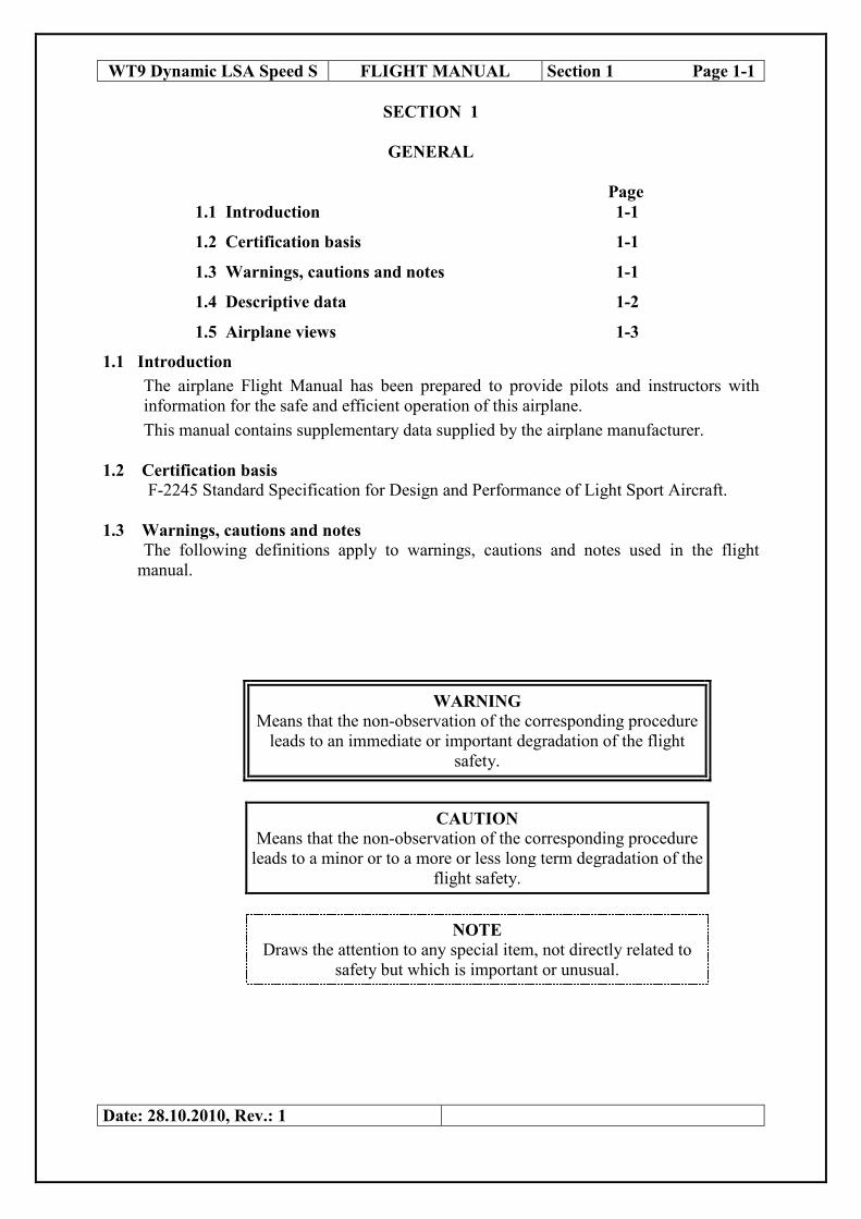
1.3 Warnings, cautions and notes The following definitions apply to warnings, cautions and notes used in the flight
manual.
WARNING
Means that the non-observation of the corresponding procedure
leads to an immediate or important degradation of the flight
safety.
CAUTION
Means that the non-observation of the corresponding procedure
leads to a minor or to a more or less long term degradation of the
flight safety.
NOTE
Draws the attention to any special item, not directly related to
safety but which is important or unusual.
Date: 28.10.2010, Rev.: 1
WT9 Dynamic LSA Speed S FLIGHT MANUAL Section 1 Page 1-2
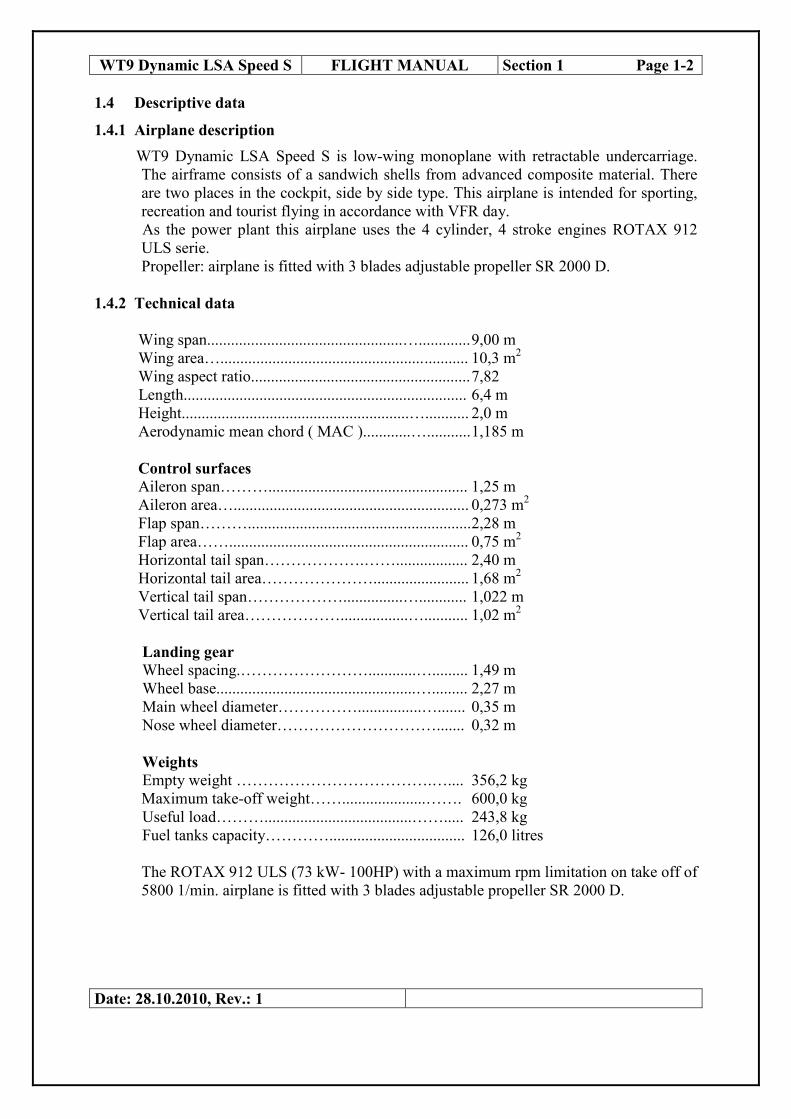
1.4 Descriptive data
1.4.1 Airplane description
WT9 Dynamic LSA Speed S is low-wing monoplane with retractable undercarriage.
The airframe consists of a sandwich shells from advanced composite material. There
are two places in the cockpit, side by side type. This airplane is intended for sporting,
recreation and tourist flying in accordance with VFR day.
As the power plant this airplane uses the 4 cylinder, 4 stroke engines ROTAX 912
ULS serie.
Propeller: airplane is fitted with 3 blades adjustable propeller SR 2000 D.
1.4.2 Technical data
Wing span.................................................…............. 9,00 m
Wing area…................................................... ........... 10,3 m2
Wing aspect ratio....................................................... 7,82
Length....................................................................... 6,4 m
Height.........................................................…........... 2,0 m
Aerodynamic mean chord ( MAC )............…........... 1,185 m
Control surfaces
Aileron span……….................................................. 1,25 m
Aileron area…........................................................... 0,273 m2
Flap span………........................................................ 2,28 m
Flap area……............................................................ 0,75 m2
Horizontal tail span……………….…….................. 2,40 m
Horizontal tail area…………………........................ 1,68 m2
Vertical tail span………………...............…............ 1,022 m
Vertical tail area……………….................…........... 1,02 m2
Landing gear
Wheel spacing.……………………............…......... 1,49 m
Wheel base..................................................…......... 2,27 m
Main wheel diameter……………................…....... 0,35 m
Nose wheel diameter…………………………....... 0,32 m
Weights
Empty weight ……………………………….….... 356,2 kg
Maximum take-off weight…….....................……. 600,0 kg
Useful load……….....................................……..... 243,8 kg
Fuel tanks capacity………….................................. 126,0 litres
The ROTAX 912 ULS (73 kW- 100HP) with a maximum rpm limitation on take off of
5800 1/min. airplane is fitted with 3 blades adjustable propeller SR 2000 D.
Date: 28.10.2010, Rev.: 1

WT9 Dynamic LSA Speed S FLIGHT MANUAL Section 1 Page 1-3
1.5. Airplane views
Date: 14.06.2011, Rev.: 2

WT9 Dynamic LSA Speed S FLIGHT MANUAL Section 1 Page 1-4
1.5.1 Three – view drawing
Date: 28.10.2010, Rev.: 1

WT9 Dynamic LSA Speed S FLIGHT MANUAL Section 2 Page 2-1
SECTION 2
LIMITATIONS
Page
2.1 Introduction 2-1
2.2 Airspeed 2-1
2.3 Airspeed indicator markings 2-2
2.4 Power plant 2-2
2.5 Power plant instrument markings 2-3
2.6 Miscellaneous instrument markings 2-4
2.7 Weight 2-5
2.8 Centre of gravity 2-5
2.9 Approved manoeuvres 2-5
2.10 Manoeuvring load factors 2-6
2.11 Flight crew 2-6
2.12 Kinds of operation 2-6
2.13 Fuel, oil 2-6
2.14 Maximum passenger seating 2-7
2.15 Other limitations 2-7
2.16 Limitations placards 2-7
2.1 Introduction
Section 2 includes operating limitations, instrument markings, and basic placards
necessary for safe operation of the airplane, its engine, standard systems and standard
equipment. The limitations included in this section and in Section 9 have been approved
by the aviation authority.
2.2 Airspeed
Airspeed limitations and their operational significance are shown below:
Speed IAS+
Remarks
km/h MPH knots
VNE Never Exceed speed 280 174 150
Do not exceed this speed in any
operation
VNO Normal Operating Limit
speed 250 156 135
Do not exceed this speed except in
smooth air, and then only with caution
VRA Rough Air speed 225 140 122
Do not exceed this speed except in
smooth air. Air movements in lee-wave
rotors, thunderclouds, visible whirlwind,
or over mountain crests are to be
understood as rough air
Date: 28.10.2010, Rev.: 1

WT9 Dynamic LSA Speed S FLIGHT MANUAL Section 2 Page 2-2
Speed IAS Remarks
km/h MPH knots
VA Manoeuvring speed 180
112 97
Do not make full or abrupt control
movement above this speed, because
under certain conditions the airplane
may be overstressed by full control
movement
VFE Maximum Flap Extended
speed 140 88 75
Do not exceed these speeds with the
given flap setting.
VLO Maximum Landing Gear
Operating Speed 140 88 75
Do not extend the landing gear above
this speed.
VLE Maximum Landing Gear
Extended Speed 250 156 135
Do not exceed this speed with the
landing gear extended.
2.3 Airspeed indicator markings
Airspeed indicator markings and their colour-code significance are shown below:
Marking IAS value or range Significance
km/h MPH knots
White arc
82 – 140 44 – 88 51 - 75
Positive Flap Operating Range. ( Lower limit
is maximum weight 1.1 VSO in landing
configuration. Upper limit is maximum speed
permissible with flaps extended positive.)
Green arc 91 – 225 57 - 140 49 – 122
Normal Operating Range. ( Lower limit is
maximum weight 1.1 VS1 at most forward c.g.
with flaps . Upper limit is VRA .
Yellow arc 225 – 280 140 - 174 122 - 150 Manoeuvres must be conducted with caution
and only in smooth air.
Yellow triangle 110 68 59 Minimum Approach speed
Yellow line 180 112 97 VA Manoevring speed
Red line 280 174 150 Maximum speed for all operations.
2.4 Powerplant
Engine Manufacturer: ROTAX-Bombardier, Gunskirchen, Austria
Engine Models: ROTAX 912 ULS
Maximum Power - Take-off: 73,5 kW / 100 HP
Continuous: 69 kW / 93,8 HP
Maximum Engine Speed – Take-off: 5800 1/min ( 5 min )
Continuous: 5500 1/min
Maximum Cylinder Head Temperature: 135 ° C
Maximum Oil Temperature: 130 ° C
Oil Pressure: Minimum: 0,8 bar ( 12 psi )
Maximum: 7 bar ( 102 psi )
Fuel Pressure: Minimum: 0,15 bar ( 2.2 psi )
Maximum: 0,4 bar ( 5.8 psi )
Fuel Grade: the following fuels can be used:
min. RON 95
Date: 28.10.2010, Rev.: 1

WT9 Dynamic LSA Speed S FLIGHT MANUAL Section 2 Page 2-3
- EN 228 Super (Unleaded Automotive Gasoline RON 95)
- EN 228 Super plus (Unleaded Automotive Gasoline RON 98)
- AVGAS 100 LL (Due to the higher lead content in AVGAS,
the wear of the valve seats, the deposits in combustion
chamber and lead sediments in the lubrication system will
increase. Therefore, use AVGAS only if you encounter
problems with vapour lock or if the other fuel types are not
available)
- Fuel E10 (unleaded gasoline blended with 10% ethanol
Oil Grade: - engine oil of a registered brand with gear additives. Use only
oil with API classification “SG” or higher.
- high performance 4-stroke motor cycle oils are recommended
- If using airplane engine oil, then only blended one.
Oil capacity: 3,0 litre
Minimum: 2,0 litre
Oil consumption: max. 0,06 l/h
WARNING Never use AVGAS, LB 95 with fully synthetic engine oils.
Propeller Manufacturer: WOODCOMP, Czech
Propeller Model: SR 2000 D, 3 blade electricaly adjustable propeller
Propeller Diameter: 1,7 m
Propeller Blade Angle 24°
Additional data can be found in Section 7, Subpart 7.9, in the Operator Manual for
engine ROTAX 912 ULS and in the User Guide for propeller SR 2000 D.
WARNING Never run the engine without propeller, this inevitably causes
engine damage and is an explosion hazard.
2.5 Powerplant instrument markings
According to customer requirement round one–purpose needle instruments could be
fitted in the instrument panel.
Date: 28.10.2010, Rev.: 1
WT9 Dynamic LSA Speed S FLIGHT MANUAL Section 2 Page 2-4
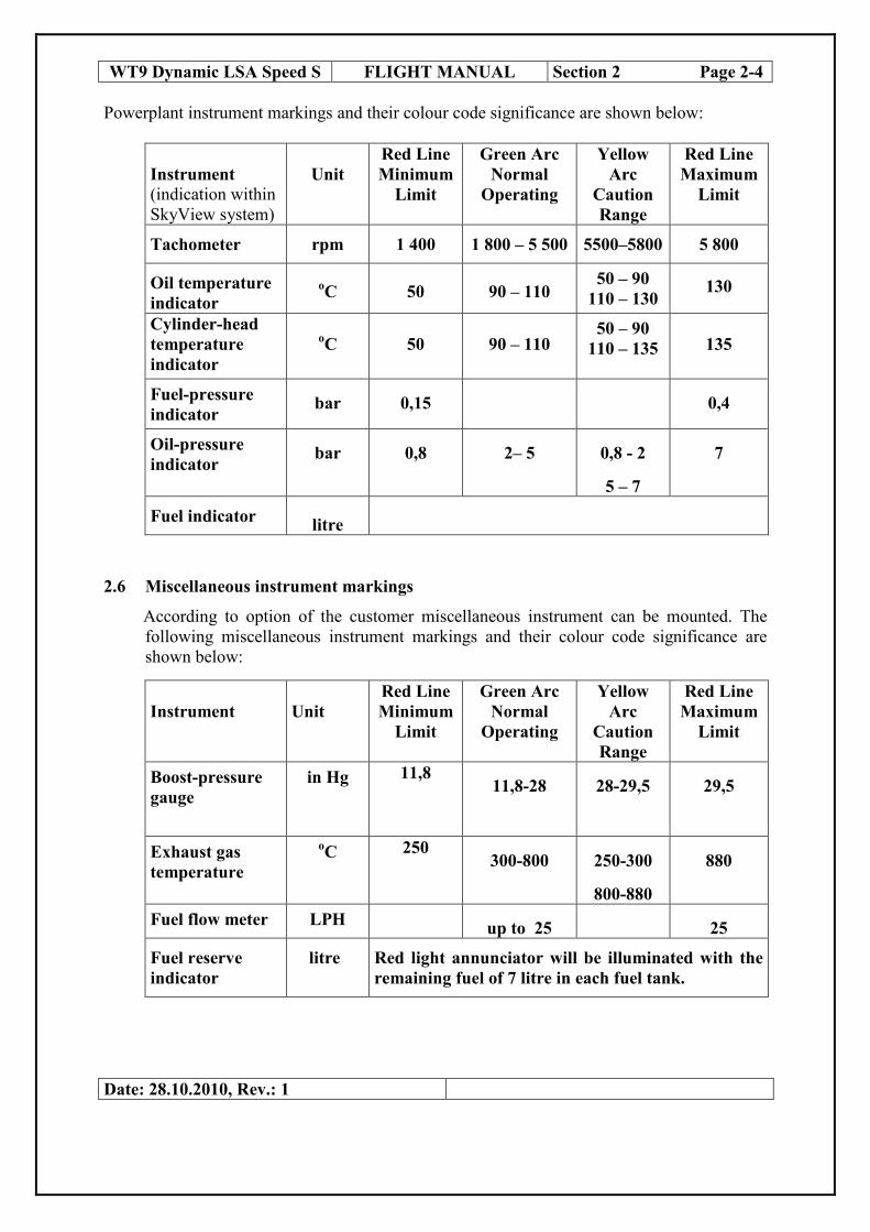
Powerplant instrument markings and their colour code significance are shown below:
Instrument
(indication within
SkyView system)
Unit
Red Line
Minimum
Limit
Green Arc
Normal
Operating
Yellow
Arc
Caution
Range
Red Line
Maximum
Limit
Tachometer rpm 1 400 1 800 – 5 500 5500–5800 5 800
Oil temperature
indicator oC 50 90 – 110
50 – 90
110 – 130 130
Cylinder-head
temperature
indicator
oC
50
90 – 110 50 – 90
110 – 135
135
Fuel-pressure
indicator bar 0,15 0,4
Oil-pressure
indicator bar 0,8 2– 5 0,8 - 2
5 – 7
7
Fuel indicator litre
2.6 Miscellaneous instrument markings
According to option of the customer miscellaneous instrument can be mounted. The
following miscellaneous instrument markings and their colour code significance are
shown below:
Instrument
Unit
Red Line
Minimum
Limit
Green Arc
Normal
Operating
Yellow
Arc
Caution
Range
Red Line
Maximum
Limit
Boost-pressure
gauge
in Hg 11,8 11,8-28 28-29,5 29,5
Exhaust gas
temperature
oC 250
300-800 250-300
800-880
880
Fuel flow meter LPH up to 25 25
Fuel reserve
indicator
litre Red light annunciator will be illuminated with the
remaining fuel of 7 litre in each fuel tank.
Date: 28.10.2010, Rev.: 1

WT9 Dynamic LSA Speed S FLIGHT MANUAL Section 2 Page 2-5
2.7 Weight
Empty weight …..……........................................ 356,2 kg
Maximum take-off weight....……...............……. 600 kg
Maximum landing weight ……................……… 600 kg
Useful load ………........................................…… 243,8 kg
Maximum fuel weight ……............................……. 89,3 kg
Maximum occupant weight per seat……......……. 115,0 kg
Minimum weight solo pilot (no baggage, full tanks)..92,9 kg
Maximum weight in Baggage Compartment…...... 40 kg
WARNING
Maximum take off weight 600 kg
2.8 Centre of gravity
Position of C.G.:
Empty airplane.....................................12 ± 2% MAC
Position of C.G. in flight…..................20 ÷ 30% MAC
Rear centre of gravity limit is valid for en-route weight at maximum crew weight.
Forward centre of gravity limit is valid for minimum pilot weight and maximum
capacity of the fuel tanks. Example to check the centre of gravity position is in Sect. 6.
2.9 Approved manoeuvres
− Steep turns with the angle of bank up to 60°°°° - appropriate entry speed is 145 km/h.
− Lazy eighths - appropriate entry speed is 145 km/h.
− Combat turns - appropriate entry speed is 200 km/h.
WARNING
Aerobatic manoeuvres and intentional spins are prohibited!
Date: 28.10.2010, Rev.: 1
WARNING
A flight shall not be commenced until the pilot-in-command
is satisfied that the mass of the airplane and centre of
gravity location are such that the flight can be conducted
safely!

WT9 Dynamic LSA Speed S FLIGHT MANUAL Section 2 Page 2-6
2.10 Manoeuvring load factors
Manoeuvre speed Speed Load factors
km/h MPH knots
VA- Manoeuvring speed 180 112 97 + 4
VNE – Never exceed speed 280 174 150 + 4
VA – Manoeuvring speed 180 112 97 - 2
VNE – Never exceed speed 280 174 150 - 2
VFE – Maximum Flap Extended
speed 140 88 75 + 2
2.11 Flight crew
The minimum flight crew with which the airplane is allowed to fly is one pilot sitting in
the left pilot seat. The passenger or another pilot may occupy the right seat in the
cockpit.
2.12 Kinds of operation
The airplane WT9 Dynamic LSA Speed S is approved to perform flights in accordance
with VFR day only. Aerobatic manoeuvres and intentional spins are prohibited!
WARNING
IFR flights and flights in icing conditions are prohibited.
For flight operations the following minimum equipment must be installed:
- Magnetic compass
- Sensitive barometric altimeter
- Airspeed indicator
- Pilot’s Safety belts
2.13 Fuel
The following fuels and oils can be used for the airplane WT9 Dynamic LSA Speed S :
see chapter 2.4 Powerplant and the Operator’s Manual for engine ROTAX 912 ULS.
Date: 28.10.2010, Rev.: 1

WT9 Dynamic LSA Speed S FLIGHT MANUAL Section 2 Page 2-7
Left tank ( l ) Right tank ( l )
The total quantity of fuel in the tank 63 63
Unusable fuel in the tank 2,9 2,9
The total usable quantity of fuel in the tank 60,1 60,1
2.14 Maximum passenger seating
The maximum number of passenger aboard is one passenger sitting in the right seat in
the cockpit.
2.15 Other limitations
a) Wind speed
The maximum crosswind component limit according to the airworthiness requirements
for take off and landing is 6 m/s, 12 knots.
b) Smoking
NO SMOKING on board the airplane.
2.16 Limitations placards
Airspeed IAS
km/h MPH knots
Never Exceed speed VNE 280 174 150
Normal Operating Limit speed VNO 250 156 135
Rough Air speed VRA 225 140 122
Manoeuvring speed VA 180 112 97
Maximum Flap Extended
speed VFE 140 88 75
Maximum Landing Gear VLO 140 88 75
Operating Speed
Maximum Landing Gear VLE 250 156 135
Exceed Speed
Date: 28.10.2010, Rev.: 1
Aerobatics, itentional spins and stalls are prohibited!
IFR flights and flights in icing conditions are prohibited!

WT9 Dynamic LSA Speed S FLIGHT MANUAL Section 2 Page 2- 8
Maximum allowed filling of the fuel tanks in litres
Baggage
weight (kg) Crew weight (kg)
140 160 170 180 190 200 210 220 230
0 full 116 103 89 75 61 47 33 19
20 116 89 75 61 47 33 19 5 0
40 89 61 47 33 19 5 0 0 0
Maximum Baggage
weight 40 kg
Date: 14.06.2011, Rev.: 2

WT9 Dynamic LSA Speed S FLIGHT MANUAL Section 3 Page 3-1
SECTION 3
EMERGENCY PROCEDURES
Page
3.1 Introduction 3-1
3.2 Engine failure 3-1
3.3 Air start 3-2
3.4 Smoke and fire 3-2
3.5 Glide 3-3
3.6 Landing emergency 3-3
3.7 Recovery from unintentional spin 3-4
3.8 Other emergencies 3-5
3.1 Introduction
Section 3 provides checklist and amplified procedures for coping with emergencies that
may occur. Emergencies caused by airplane or engine malfunction are extremely rare if
proper preflight inspections and maintenance are practised.
However, should an emergency arise, the basic guidelines described in this section
should be considered and applied as necessary to correct the problem.
3.2 Engine failure
3.2.1 Engine failure at take-off roll
1. Throttle lever - set to idle position
2. Ignition/ Starter switch - switch off
3. Brakes - apply till stop
3.2.2 Engine failure at take-off up to height 50 m
1. Airspeed - modify to 120 km/h
2. Field selection - land straight ahead no more than 15° left or right into
wind if possible..
3. Ignition/ Starter switch - switch off
4. Fuel selector valve - close
3.2.3 Engine failure at take-off above height 50 m
1. Airspeed - modify to 120 km/h
2. Field selection - select in the direction of the free area without obstacles,
if possible into wind
3. Ignition/ Starter switch - switch off
4. Fuel selector valve - close
5. Flaps - extend as required
Date: 28.10.2010, Rev.: 1

WT9 Dynamic LSA Speed S FLIGHT MANUAL Section 3 Page 3-2
3.2.4 Engine failure in flight
1. Airspeed - modify to 120 km/h
2. Field selection - according to height available
3. Air start - in accordance with item 3.3
4. In case of an unsuccessful air start, perform emergency landing in accordance
with item 3.6.1.
3.2.5 Performance loss and irregular running of the engine during flight
This situation may occur with carburettor icing.
Apply carburettor pre-heating as required to restore normal power, smooth running.
Or it can happen because of empty fuel tank, the indicator is the fuel pressure loss –
select the non empty fuel tank. If everything fails perform an emergency landing.
3.3 Air start
1. Airspeed -modify to 120 km/h
2. Altitude flight - check
3. Field selection - select according to height available
4. Fuel selector valve - open
5. Choke - if the engine is already in operating temperature,
start the engine without choke
6. Throttle lever - at cold engine set to idle position
- at warm engine slightly open
7. Ignition/ Starter switch - position “both” starting for max. 10 sec. only
without interruption
As soon as engine runs, adjust throttle to achieve smooth running at 2500 r.p.m for
approximately half a minute before increasing power as required.
WARNING
The rate of descent approx. 2.5 m/s causes measurable loss of
altitude during the air start. If the air start is unsuccessful up to
height 150 m above ground level, perform emergency landing
according to item 3.6.1.
3.4 Smoke and fire
3.4.1 Engine fire on the ground
1. Fuel selector valve - close
2. Throttle lever - full open
3. Ignition/ Starter switch - switch off after consumption of the fuel
4. Crew - leave the cockpit immediately
5. Extinguish fire - with best available means
3.4.2 Engine fire in flight
1. Fuel selector valve - close
2. Throttle lever - full open
3. Ignition/ Starter switch - switch off after consumption of the fuel
Date: 28.10.2010, Rev.: 1

WT9 Dynamic LSA Speed S FLIGHT MANUAL Section 3 Page 3-3
4. Try to extinguish the fire with side slip
5. Perform emergency landing in accordance with item 3.6.1.
CAUTION
After extinguishing the fire do not start engine again!
3.4.3 Fire in cockpit
1. Fire source - locate
2. Ignition/ Starter switch - switch off
3. Bat1, Bat2 - switch off
4. Crew - leave the cockpit on the ground ,
- perform emergency landing accordance with item 3.6.1.
5. Try to extinguish - with best available means
3.5 Glide
Glide path will determine the field selection for emergency landing. The optimum
gliding performance is with retracted wing flaps and with stopped propeller.
In case of engine failure it is necessary to maintain the following optimum speeds for
given configuration.
Optimum descent
airspeed IAS km/h MPH knots
120 75 65
Maximum gliding range 11
Rate of descent 3,1 m/s 620 ft/min
3.6 Landing emergency
3.6.1 Emergency landing
1. Airspeed - modify to 120 km/h
2. Field selection - select in the direction of the free area without
obstacles, if possible into wind
3. Seat belts and harness - fasten
4. Extend landing gear - during landing on airfield or similar surface
5. Flaps - extend as required
6. Fuel selector valve - close
7. Ignition/ Starter switch - switch off
8. Bat1, Bat2 - switch off
CAUTION
The loss of height for 360 ° turn is approx.. 200 m.
Date: 28.10.2010, Rev.: 1

WT9 Dynamic LSA Speed S FLIGHT MANUAL Section 3 Page 3-4
3.6.2. Precautionary landing
In the event of the airplane failure, disorientation, shortage of fuel, dangerous
deterioration of the meteorological conditions (visibility, thunderstorm) and
approaching sunset, a precautionary landing should be conducted.
1. Select a suitable landing field, if possible into the wind.
2. Fly over selected field with wing flaps 15° and 120 km/h airspeed at a height
50 m AGL, noting the preferred area for touchdown for the next landing approach
to inspect the terrain for obstructions and surface conditions.
3. Make landing circuit at a height 150 m AGL or at a safe altitude in accordance
with the ceiling with flaps 15° and 120 km/h airspeed. Extend “down wind”
position and make approach with sufficient power.
4. Don’t lose sight of the selected field in low visibility.
5. Landing approach with flaps for landing and sufficient power.
6. Arrange approach so that the desired touch down spot will be immediately after
passing the edge of the selected landing field.
7. After touch down apply heavy breaking till stopped. ground loop if necessary.
8. When the airplane comes to a stop, shut down the engine, master switch off, Main
fuel selector close, secure the airplane and seek assistance.
3.6.3 Landing with a flat tyre
1. Landing approach - with flaps 38 ° and 110 km/h airspeed
2. Touch down - with the bank angle on the unflat tyre at minimum
touch down speed,
3. Direction after landing - maintain ground roll direction.
3.7 Recovery from unintentional spin
For recovery from an unintentional spin the following procedure should be used:
1. Throttle lever - set to idle position
2. Control stick - set neutral position, without deflection of the
ailerons
3. Rudder control - apply full rudder opposite to the direction of
rotation
4. Control stick - move forward of neutral in a brisk motion until
rotation stops.
5. Rudder control - immediately as rotation stops, neutralize rudder
position
6. Control stick - make a smooth recovery from the resulting dive.
WARNING
Intentional spins are prohibited!
Date: 28.10.2010, Rev.: 1

WT9 Dynamic LSA Speed S FLIGHT MANUAL Section 3 Page 3-5
3.8 Other emergencies
3.8.1 Control failures
Aileron control fault - the airplane is possible to control laterally by
the secondary effect of the rudder. Start and
termination of the yawing up to bank angle 15°
is possible using the rudder only.
Rudder control fault - the yawing and the termination is conducted
with help of the lateral control of the ailerons.
3.8.2 Vibrations
The power plant can be the source of the vibrations.
1. Reduce engine speed to minimize the vibrations.
2. Proceed to the nearest airport for landing or select a suitable precautionary landing
field in accordance with item 3.6.2.
3.8.3 Emergency extension of the undercarriage
An overswitch on the instrument panel labelled “HYDRLCS” is in the up position at
normal operation. In case of the electrical driven hydraulic pump malfunction or the
overswitch is set in the down position, the emergency extension of the undercarriage is
carried out by its own mass with the help of a three-way valve. “HYDRLCS
OFF/INOP” light on announciator panel gets illuminated. The drag stay is arrested
with the help of the springs. The undercarriage is extended even in an electrical power
loss. The emergency extension of the undercarriage is terminated, when “three green”
lights are illuminated on the gear announciator panel.
Fig. 2 Emergency extension of L/G overswitch
3.8.4 Rescue system
For operation and handling with rescue system to see Operation manual delivered by
producer of equipment. See Section 9 “Supplement”
Date: 14.06.2011, Rev.: 2

WT9 Dynamic LSA Speed S FLIGHT MANUAL Section 3 Page 3-6
3.8.5 Unsecured cockpit canopy
If the „Before Take-off“ Checklist is performed insufficiently (page 4-9, paragraph
4.5.5. , point 14 canopy of cockpit – latched, locked), there is a danger of partial
cockpit canopy latching or non locking. The canopy is equipped with a lock on the
upper rear section of the frame and it is secured by the lock lever shot backwards. The
lock pin is projected as latch with compression spring. The gap cca. 8-12 mm will be
rise between fuselage and cockpit canopy, which is constant during straight line flight
without side-slipping due to the air flow and the function of the gas struts. Partial
cockpit canopy latching or non locking will stack up by the noise increase due to the
agitated air through the gap between fuselage and cockpit canopy. Partial cockpit
canopy latching is possible to close safely during straight line flight without side-
slipping by the following way according to appropriate stage of flight:
3.8.5.1 During take-off roll
1. Abort the take-off, if the cockpit canopy unlatching, unlocking is detected during
take-off roll.
2. Latch and lock the cockpit canopy by normal procedure after stopping. (the cockpit
canopy handle pull down and check the cockpit canopy latching and locking by
canopy frame and the red ring position ) (see page 7-6, paragraph 7.8)
3.8.5.2 After unstick or during climbing
1. Safely terminate take-off
2. Climb to safety altitude
3. Fly straight line flight without side-slipping and carry out procedure for level flight.
3.8.5.3 Level flight
1. Open the left ventilation sliding window on cockpit canopy
2. Reduce speed to 120 km/h
3. Hold control stick by one hand
4. The cockpit canopy handle pull down for cockpit canopy latching and locking
5. Check the cockpit canopy latching and locking by canopy frame and red ring
position
6. Close the left ventilation sliding window on cockpit canopy
7. Adjust flight airspeed to cruising speed
Date: 14.06.2011, Rev.: 2
WARNING
During side-slipping flights ( incorrect turn –slipping turn, skidding turn, and side
slipping for landing ) with partial cockpit canopy latching or non locking due to
asymmetrical flow over fuselage by the air flow, the cockpit canopy will be carved
through the gap and subsequently will be full open by help of the gas struts. The cockpit
canopy will become the braking shield, what will cause abnormal airplane descent due to
increased total drag.

WT9 Dynamic LSA Speed S FLIGHT MANUAL Section 4 Page 4-1
SECTION 4
NORMAL PROCEDURES
Page
4.1 Introduction 4-1
4.2 Rigging and derigging 4-1
4.3 Daily inspection 4-4
4.4 Preflight inspection 4-4
4.5 Normal procedures and check list 4-7
4.1 Introduction
Section 4 provides checklist and amplified procedures for the conduct of normal
operation. Normal procedures associated with optional systems can be found in
Section 9.
4.2 Rigging and derigging
4.2.1 Rigging of the wings
The airplane has the wings disassembled for transportation purposes or to save space
in the hangar. There is a description for the rigging procedure of the right wing. The
procedure for the left wing is analogous. Thoroughly clean and lubricate all the wing
fittings and pins so pins locate easily.
Rigging:
1. Fit the spar end of the right wing into the spar end (fork) of the wing central
section and push the wing along its longitudinal axis so that a connection slot
between the wing central section and the wing root is approx. 100 mm ( Fig. 3 ).
Connect the hoses from the Pitot-static tube and prepare and adjust the wing fuel
tank hoses, connect the wiring for fuel tank conductive connection ans position
lights
2. Fully push the wing into the wing central panel and slide the wing tank fuel
houses on theirs sockets together with theirs clamps. Carefully insert the pin of the
extended wing flap hinge into the fitting of the wing central panel. Take care of
the hoses from the Pitot-static tube and for fuel houses they must not be twisted.
3. Insert wing pins to connect wing spar end with the wing central panel. The outer
pin is inserted through the access hole on the lower wing surface . The inner pin is
inserted through the hole in the cockpit below pilot seat ( slightly lift and lower
the wing tip to ease the pin insertion ).
4. Insert rear spar into the fitting to lecate the rear spar to the centre section. Secure
all 6 pins with safety pins ( Fig.4 ).
5. Insert connecting pin of the flap rod. During this procedure the flap control lever
in the cockpit shall be set to the rearmost position and the flap shall be deflected
to maximum down position.
Date: 28.10.2010, Rev.: 1

WT9 Dynamic LSA Speed S FLIGHT MANUAL Section 4 Page 4-2
7. Connect the aileron control rod with the rod in the wing centre section and secure
the nut ( Fig.4 ) with the safety pin. Than tight the fuel houses clamps.
8. Repeat the procedure with the second wing. After checking the security of the all
connection. The connection slot between wing and the wing centre section should
be sealed with sticky tape.
WARNING
After rigging of the wings check for correct operation and security of the
aileron control pins and the flap control pins as well as the connection of the
hoses from the Pitot-static tube and fuel houses.
Fig. 3 Insertion of the wing spar into the wing centre section, position of the
wing pins and the support points.
Fig. 4. Connecting bolt + safety pin of aileron connection.
Date: 28.10.2010, Rev.: 1
Jacking pionts for lifting the
airplane (below rear spar of
wing centre section and
below the firewall.
Insertion of the
wing spar
Safety pin ( No.3 at the rear spar with the
security )
Attachment bolt
of the aileron rod

WT9 Dynamic LSA Speed S FLIGHT MANUAL Section 4 Page 4-3
4.2.2 Derigging of the wings
Use the opposite sequence for derigging:
1. Drain central section fuel tanks and wing tanks
2. Disconnect aileron rod from the rod in the wing centre section.
3. Remove the sticky tapes from the connection slot between wing and the wing
centre section. Unlock the joints of the flap shaft.
4. Pull out all wing pins. (Pull out the fixation pins for connection of the wing spar
end with the wing central panel and the auxiliary rear pin.)
5. Pull out the wing along its longitudinal axis so that there is a distance between the
wing and the wing root of approx. 100 mm (Fig. 3). Disconnect the hoses from
the Pitot-static tube, the wing fuel tank hoses, disconnect the wiring for fuel tank
conductive connection and position lights.
6. Carefully pull the wing away from the wing centre section and put on soft mats.
Fig. 5 Connecting position for the flap and the aileron.
Date: 28.10.2010, Rev.: 1
Flapshaft
Aileron rod
connection
WT9 Dynamic LSA Speed S
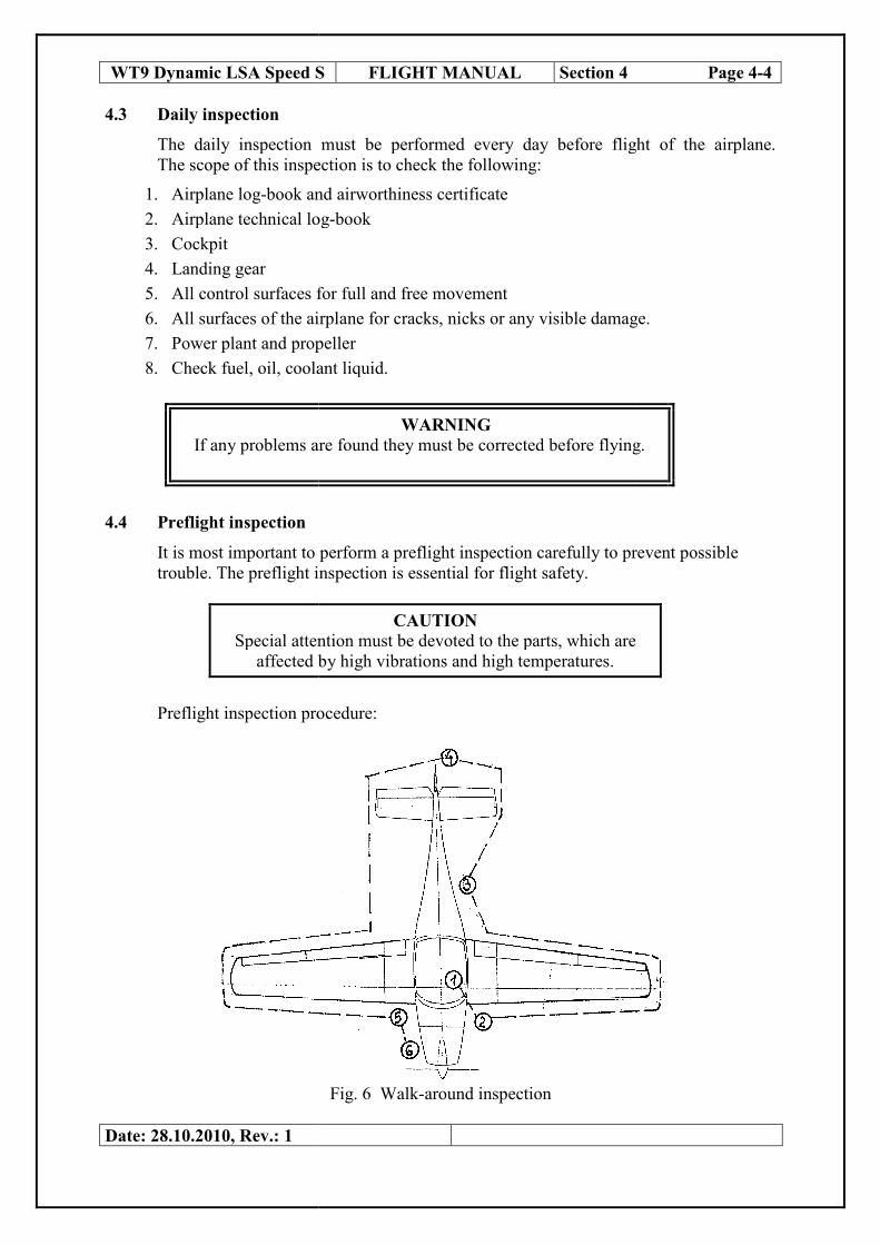
4.3 Daily inspection
The daily inspection must be performed every day before flight of the airplane.
The scope of this inspection is to check the following:
1. Airplane log-book and airworthiness certificate
2. Airplane technical log
3. Cockpit
4. Landing gear
5. All control surfaces for full and free movement
6. All surfaces of the airplane for cracks, nicks or any visible damage.
7. Power plant and propeller
8. Check fuel, oil, coolant liquid.
If any problems are found they must be corrected before flying.
4.4 Preflight inspection
It is most important to perform a preflight inspection carefully to prevent possible
trouble. The preflight inspection is essential for flight safety.
Special attention must be devoted to the parts, which are
affected by high vibrations and high temperatures.
Preflight inspection procedure:
Date: 28.10.2010, Rev.: 1
WT9 Dynamic LSA Speed S FLIGHT MANUAL Section 4 Page 4
The daily inspection must be performed every day before flight of the airplane.
The scope of this inspection is to check the following:
book and airworthiness certificate
Airplane technical log-book
All control surfaces for full and free movement
All surfaces of the airplane for cracks, nicks or any visible damage.
Power plant and propeller
oil, coolant liquid.
WARNING If any problems are found they must be corrected before flying.
It is most important to perform a preflight inspection carefully to prevent possible
inspection is essential for flight safety.
CAUTION
Special attention must be devoted to the parts, which are
affected by high vibrations and high temperatures.
Preflight inspection procedure:
Fig. 6 Walk-around inspection
Section 4 Page 4-4
The daily inspection must be performed every day before flight of the airplane.
All surfaces of the airplane for cracks, nicks or any visible damage.
If any problems are found they must be corrected before flying.
It is most important to perform a preflight inspection carefully to prevent possible
Special attention must be devoted to the parts, which are

WT9 Dynamic LSA Speed S FLIGHT MANUAL Section 4 Page 4-5
1. Cockpit:
Flight controls - check for freedom of movement
BAT 1 - switched off
BAT 2 - switched off
Ignition/ Starter switch - position off
Electrical control switches - all off
Circuit brakers - all in
Gear operating switch - down
Loose items - secure or remove
Cockpit canopy glass - clean, check cockpit canopy lock
Safety harness - inspect
2. Wing
Surface - state of wing surface
Connection - wing pins fully inserted and secured
Pitot static tube - pitot tube cover removed, check opening for blockage.
Leading edges - without damage, clean
Ailerons - check for freedom of movement and security
Flaps - without play, check hinges for security
3. Fuselage
Surface - without damage
Static pressure receivers - check opening for blockage
Antennas - fixed, without damage
Cockpit wing walks - without damage
4. Tail units
Surface - without damage
Control surfaces - check for freedom of movement , without excess play
Auxiliary tail skid - check for secure attachment
5. Landing gear
Main wheel tyres - state, inflation ( 250 kPa )
Brakes - visually check condition of pads, brake system
for leaks
Legs - state without damage, attachment
Nose wheel leg - nose wheel tyre state, inflation ( 200 kPa )
attachment, suspension check, wheel free
rotation
Date: 14.06.2011, Rev.: 2

6. Powerplant
Propeller - attachment, leading edge blade state, check for nicks and security,
check spinner for cracks and attachment.
Engine - check for any operating fluids leaks below
engine cowlings
- state of the cowlings
- state of the exhaust system attachment
- check coolant level and oil level
- turn the propeller by hand several times for odd
noises or excessive resistance and normal
compression.
WARNING Before cranking the propeller switch off both ignition circuits. The
propeller must be caught at the blade surface every time. Do not catch
at the edge.
WT9 Dynamic LSA Speed S FLIGHT MANUAL Section 4 Page 4-6
Date: 28.10.2010, Rev.: 1

WT9 Dynamic LSA Speed S FLIGHT MANUAL Section 4 Page 4-7
4.5 Normal procedures and check list
The standard cockpit control arrangement is shown in fig.7 and the actual instrument
panel is shown in fig.9.
Fig. 7. The standard cockpit controls (see also fig.9 on page 7 – 3)
1. Control stick 9. Instrument panel
2. Rudder pedals 10. Ventilation sliding window
3. Trim lever 11. Ventilation flow baffle
4. Brake control lever 12. Choke
5. Flaps lever 13. Ignition, Starter key, Master
6. Pocket switch
7. Headset socket / jack 14. Tachometer
8. Seat and safety belt 15. GPS, Radio, Transponder
16. Powerplant instruments
17. Flight instruments
18. Throttle lever
Date: 28.10.2010, Rev.: 1
1 3
2
4
18
6
7
8
9
10
11
12
13
1415
16 17
5

WT9 Dynamic LSA Speed S FLIGHT MANUAL Section 4 Page 4-8
4.5.1 Before starting engine
1. Ignition/ Starter switch - position off
2. Rudder pedals - freedom of movement
3. Control stick - freedom of movement
4. Throttle lever - freedom of movement, set to idle position
5. Seat and safety harness - adjust and lock
6. Brake - set “brake” position
7. Canopy of cockpit - shut and latched
4.5.2 Engine starting
WARNING
Before starting engine check position of the landing gear overswitch .
Overswitch position – EXTENSION ( L/G extended ).
Cold engine: 1. Fuel selector valve - select left tank
2. Choke - set open
3. Throttle lever - set to idle position
4. Bat 1 - switch on
5. Bat 2 - switch on
6. Storbe lights - switch on
7. Fuel pump - switch on for 5 sec. than switch off
8. Ignition/ Starter switch - position “both” starting for max. 10 sec. Only
without interruption
9. Hydraulics - switch on
10. Avionics - switch on
11. As soon as engine runs - adjust throttle lever to achieve smooth running
at approximately 2000 r.p.m, choke off
12. Oil pressure - check in green
13. Voltage - check in green
14. Generator - check “OK”
15. Alternator - check > 0 Amps
16. Nav lights - as required
17.Dashboard lights - as required
18.Handle control rescue system - remove secure lock
Warm engine: if the engine is already at operating temperature
1. Fuel selector valve - select left tank
2. Choke - set close
3. Throttle lever - set to slight open position
4. Bat 1 - switch on
5. Bat 2 - switch on
6. Storbe lights - switch on
7. Fuel pump - switch on for 5 sec. than switch off
8. Ignition/ Starter switch - position “both” starting for max. 10 sec. Only
without interruption
Date: 14.06.2011, Rev.: 2

9. Hydraulics - switch on
10. Avionics - switch on
11. As soon as engine runs - adjust throttle lever to achieve smooth running
at approximately 2000 r.p.m
12. Oil pressure - check in green
13. Voltage - check in green
14. Generator - check “OK”
15. Alternator - check > 0 Amps
16. Nav lights - as required
17.Dashboard lights - as required
18.Handle control rescue system - remove secure lock
4.5.3 Engine warming up
In accordance with the Operator’s Manual for all versions of ROTAX 912 as follow:
Start warming up period at 2000 r.p.m for approx. 2 minutes, continue at 2500 r.p.m,
duration depending on ambient temperature, until oil temperature reaches 50 oC.
Engine ground test:
1. Ignition check – check the two ignition circuits at 4000 r.p.m. Speed drop with
only one ignition circuit must not exceed 300 r.p.m. Max. difference 115 r.p.m of
speed by use of either circuit A or B
2. Throttle response – short full throttle ground test, speed must not exceed 5800 r.p.m.
3. The minimum speed on the ground must be 5000 r.p.m depending on ambient
temperature and pressure
4. Check idle speed 1800 r.p.m
4.5.4 Taxying
Use of the throttle will help with smooth adjustments of power during taxying.
Taxying of the airplane is controlled by he rudder pedals which are connected to the
nose wheel steering. The wheel brakes are actuated by sliding the brake lever
rearwards in the centre console.
4.5.5. Before take-off
1. Rudder pedals - freedom of movement
2. Control stick - freedom of movement
3. Elevator trim control - set to green line
4. Wing flaps - as required
5. Fuel selector valve - left tank
6. Fuel pump - switch on
7. Pitot heating - as required
8. Landing gear operating switch - down
9. Hydraulics - check switched on
10. Power plant instrument - check for correct reading; green
11. Flight instruments - check altimeter setting
12. Propeller - set 5400 r.p.m. (take off position)
13. Seat and safety harness - adjust and lock
14. Canopy of cockpit - latched
WT9 Dynamic LSA Speed S FLIGHT MANUAL Section 4 Page 4-9
Date: 14.06.2011, Rev.: 2

WT9 Dynamic LSA Speed S FLIGHT MANUAL Section 4 Page 4-10
4.5.6. Normal Take-off
- Throttle lever – full open
- control stick set into neutral position
- direction on the ground run controlled by rudder pedals
- unstick at speed at 80-85 km/h ( according to take off weight )
- accelerating at speed 110-120 km/h ( acceleration after unstick )
- at positive climb gear up
- at height 50 m AGL wing flaps up
4.5.7. Climbing
Normal climbs are conducted at climb speeds 130 - 140 km/h in accordance with the
take off weight of the airplane. Monitor cylinder head temperature and oil pressure
during climb. Oil temperature limits must not be exceeded. In case of high readings,
increase airspeed and reduce engine power setting. At safety altitude switch fuel pump
off.
4.5.8. Cruise
The range of cruising speeds is from 140 to 230 km/h in accordance with the engine
speed setting from 4000 to 5500 r.p.m. The economy airspeed for best fuel economy
is at 180 km/h, the optimum operation is between 180 km/h to 230 km/h. In case of
turbulence reduce cruising speed below 180 km/h. Under certain conditions the
airplane may be overstressed. The airplane is able to be trimmed through the range of
the cruising speeds. Due to economy reasons is recommended to maintain the
following data:
Engine
ROTAX 912 ULS
Engine power setting
Engine
Speed
( r.p.m )
Performance
( kW )
Torque
( Nm ) Manifold pressure
( in Hg )
Take-off power 5 800 73,5 119,0 27,5
Max. continuous power 5 500 69,0 121,8 27
75 % 5 000 51,0 97,4 26
65 % 4 800 44,6 88,7 26
55 % 4 300 38,0 84,3 24
Date: 14.06.2011, Rev.: 2

WT9 Dynamic LSA Speed S FLIGHT MANUAL Section 4 Page 4-11
4.5.9. Descending
Descending is conducted at airspeeds 120 – 130 km/h with the throttle lever set to
idle position. For increasing the rate of descent it is recommended wing flaps set to
landing position ( 38° flaps deflection ) and proceed at airspeed 120 km/h. In this
configuration the gliding range is 1:8.
Side slipping is conducted with airspeed 120 km/h, and bank angle 30° with help of
the full rudder deflection. The side slip direction is controlled by the bank.
4.5.10 Landing
Check systems of a fuel before approach for landing. Landing approach conduct at
small glide slope angle due to long distance of the float before aeroplane touch-down
1. Mannifold pressure - 15 in. Hg
2. Propeller - set 5.400 rpm
3. Fuel valve - left tank
4. Fuel pump - switch on
5. Landing light - switch on
6. Landing gear operating switch - below 80KIAS down,
check 3 greens
7. Wing flaps - as required flaps down at speed
below 140 km/h
8. Approach speed - 110-120 km/h according to the
weight and wind
9. Elevator trim - adjust as required
10. Actual touch down should be made with power-idle and on the main
wheel first. The nose wheel should be lowered smoothly to the runway
as speed is diminished
11. During landing run control the aeroplane with help of the rudder pedals.
12. Apply braking as required. The main wheel brakes are actuated via the
handle on the pedestall between the pilot seats.
4.5.11 Balked landing
1. Smoothly adjust the throttle lever – full open ( a thrust yawing moment is
manifested in case of the steep setting of the throttle lever )
2. Airspeed modify to 120 km/h
3. The wing flaps setting reduced to take-off position
4. Elevator trim – adjust as required and proceed in the climb out
Date: 14.06.2011, Rev.: 2

WT9 Dynamic LSA Speed S FLIGHT MANUAL Section 4 Page 4-12
4.5.12 After landing
1. Engine r.p.m. - adjust throttle for taxying
2. Wing flaps - retract
3. Elevator trim - set to rearmost position of neutral
4. Landing gear - check if in down position
5. Fuel pump - switch off
6. Landing lights - switch off
7. Taxy ing - to the parking position
4.5.13. Securing aeroplane
1. Brakes - set “park” position
2. Throttle - set idling
3. All electrics switches except strobe. - switch off
4. Ignition/ Starter switch - position “left” after 2-3 s. position “off”
5. Bat 1 - switch off
6. Bat 2 - switch off
7. Handle control rescue system - secure with the lock
8. After leaving the cockpit, the canopy should be covered with the cloth dust
cover, to avoid the effects of the sun.
Date: 14.06.2011, Rev.: 2

WT9 Dynamic LSA Speed S FLIGHT MANUAL Section 5 Page 5-1
SECTION 5
PERFORMANCE
Page
5.1 Introduction 5-1
5.2 Approved data 5-1
5.2.1 Airspeed indicator system calibration 5-1
5.2.2 Stall speed 5-2
5.2.3 Take-off performance 5-2
5.2.4 Landing distance 5-2
5.2.5 Climb performance 5-2
5.3 Additional information 5-3
5.3.1 Balked landing climb 5-3
5.3.2 Effect on flight performance and characteristics 5-3
5.3.3 Demonstrated crosswind performance 5-3
5.3.4 Noise data 5-3
5.1 Introduction
Section 5 provides approved data for airspeed calibration, stall speed and take-off
performance and non-approved additional information. The data in the charts has
been computed for condition of the standard atmosphere from actual flight tests with
the airplane at maximum take-off weight and engine in good condition and using
average piloting techniques.
5.2 Approved data
5.2.1 Airspeed indicator system calibration
IAS ( km/h ) 50 55 60 100 112 125 137 146 165 176 184
CAS ( km/h ) 55 60 65 100 110 120 130 140 160 170 180
IAS ( km/h ) 203 225 245 267 285
CAS ( km/h ) 200 220 240 260 280
IAS = indicated airspeed
CAS = calibrated airspeed
Date: 28.10.2010, Rev.: 1

WT9 Dynamic LSA Speed S FLIGHT MANUAL Section 5 Page 5-2
5.2.2 Stall speed
Maximum weight 600 kg, C.G. in 30% MAC, idle engine speed
Position wing flaps 0°°°° 15°°°° 38°°°°
Stall speed IAS in km/h 85 76 70
Stall speed CAS in km/h 87 79 74
5.2.3 Take-off performance
The data is valid for following conditions: MTOW 600kg, H = 260 m MSL,
Temperature t = 15 ° C, Wing flaps position 15°, engine ROTAX 912 ULS, propeller
SR 2000 D
Surface of the
runway
Take-off run
distance
( m )
Take-off distance up
to 15m
( m )
Paved runway 147 313
Non paved – grass 173 348
5.2.4 Landing distance
The data is valid for following conditions: H = 260 m MSL, Temperature t = 15 ° C
Wing flaps position 38° , landing speed 1,3 VSo, landing roll is braked.
Surface of the
runway
Landing distance (m)
from height 15 m
Landing roll
distance ( m )
Paved runway 263 75
Non paved - grass 272 84
5.2.5 Climb performance
The data is valid for max.weight 600 kg , without flaps, ROTAX 912 ULS,
engine speed 5000 r.p.m, propeller SR 2000 D
Altitude (m MSL) Speed IAS km/h Rate of climb m/s
0 130 4,55
1000 130 3,16
2000 130 2,54
The service ceiling is 5500 m at the max. continuous power.
Date: 28.10.2010, Rev.: 1

WT9 Dynamic LSA Speed S FLIGHT MANUAL Section 5 Page 5-3
5.3 Additional information
5.3.1 Balked landing climb
The data is valid for maximum landing weight 600 kg , wing flaps position 38o.
Engine ROTAX 912 ULS, engine speed 5500 r.p.m, SR 2000 D
Flight altitude (m) Airspeed IAS km/h Rate of climb m/s
0 120 4,22
1000 120 2,85
2000 120 2,20
5.3.2 Effect on flight performance and characteristics
No disturbing effects on flight performance and characteristic of the aeroplane WT-9
Dynamic LSA Speed were recorded during the flight tests.
5.3.3 Demonstrated crosswind performance
The maximum demonstrated crosswind speed for take-off and landing is 6 m/s
according to the airworthiness requirements.
5.3.4 Noise data
The maximum noise data 56,7 dB (A) was measured during the flight tests according
to the German noise requirement LS – UL 96.
Date: 28.10.2010, Rev.: 1

WT9 Dynamic LSA Speed S FLIGHT MANUAL Section 6 Page 6-1
SECTION 6
WEIGHT AND BALANCE / EQUIPMENT LIST
Page
6.1 Introduction 6-1
6.2 Weighing procedure 6-1
6.3 Weight and balance record and permitted
payload range 6-2
6.4 Master minimum equipment list 6-4
6.1 Introduction
This section contains the payload range with which the airplane may be safely
operated. C.G. position is very important parameter which effects the safety of flight.
NOTE
Weight and balance data listed in this section is informative.
True data will be given after manufactured plane balancing
6.2 Weighing procedure
To define the airplane C.G. it is necessary to weigh the empty airplane with standard
and optional equipment, with operating fluids of the engine but without the fuel
in the tanks.
The airplane is weighed with the help of three weighing-machines located below
the left and right main wheels and below the nose wheel. The airplane position
for weighing has to be parallel with the horizontal plane which passes through
the side edge of the cockpit. The reference point (datum point = DP) is leading edge
of wing root section. To measure the distance from centre of main landing wheel axle
and of nose wheel axle to reference point DP. C.G. position is calculated from
the reference point DP (leading edge) and C.G. position is calculated in %
aerodynamic mean chord (MAC) too. The leading edge of the MAC is located
in distance 77 mm rear from DP.
Centre of gravity position after loading airplane (crew, fuel, baggage or additional
equipment) is calculated as following: The sum moments of airplane all components
mass is added to the total moment of the empty airplane and divided by total weight.
Date: 28.10.2010, Rev.: 1
WT9 Dynamic LSA Speed S FLIGHT MANUAL Section 6 Page 6-2
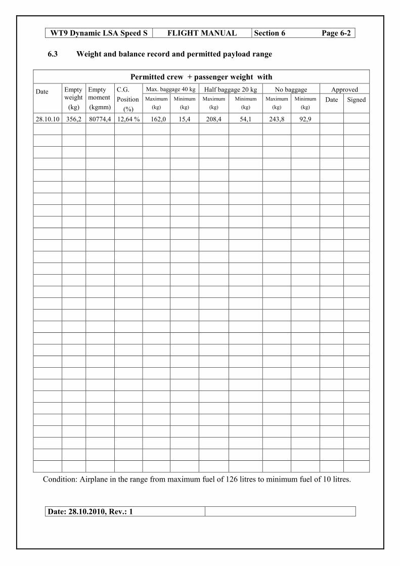
6.3 Weight and balance record and permitted payload range
Permitted crew + passenger weight with
Date Empty
weight
(kg)
Empty
moment
(kgmm)
C.G.
Position
(%)
Max. baggage 40 kg Half baggage 20 kg No baggage Approved
Maximum
(kg)
Minimum
(kg)
Maximum
(kg)
Minimum
(kg)
Maximum
(kg)
Minimum
(kg)
Date Signed
28.10.10 356,2 80774,4 12,64 % 162,0 15,4 208,4 54,1 243,8 92,9
Condition: Airplane in the range from maximum fuel of 126 litres to minimum fuel of 10 litres.
Date: 28.10.2010, Rev.: 1

WT9 Dynamic LSA Speed S
Type: WT – 9 DYNAMIC
Type landing-gear
RETRACTABLE
Type of Scale 3 x 500 NDS
Weighing Point Scale Reading(kg)
Nose wheel 112,2
Right main wheel 127,1
Left main wheel 116,9
Total Weight 356,2
Fuel
Weight = 356,2 kg Oil and coolant including C.G. position from DP = Moment / Weight 80774,4
XT (mm) 356,2 - 77
32627,8 1185 Permitted C.G. range of empty aeroplane XCalculated position of C.G. is within an permitted range
Place, Date: 22.06.2006
Prievidza 28.10.2010
Date: 28.10.2010, Rev.: 1
WT9 Dynamic LSA Speed S FLIGHT MANUAL Section 6 Page 6
gear:
RETRACTABLE Registration:
OK - WOW
S/N:
DY - 391/2010 LSA
Date of production:
28.10
Calibration valid till 01.06.201
Scale Reading(kg) Distant from DP (mm) Moment (kg mm)
a = - 748 -
b = 675
b = 675
Total Moment =
240
Moment = 80774,4
C.G. position from DP = Moment / Weight - 77
150
= 150 mm XCT % MAC 1185
32627,8 1185
Permitted C.G. range of empty aeroplane XCT is from 10 to 14 % MAC. Calculated position of C.G. is within an permitted range.
.06.2006
Prievidza 28.10.2010 ........................................ Superviso
Section 6 Page 6-3
Date of production:
28.10.20106
01.06.2012
Moment (kg mm)
-83925,6
85792,5
78907,5
80774,4
80774,48 kg/mm
x 100 = 12,6 %
32627,8 1185
........................................ Supervisor / Signature

WT9 Dynamic LSA Speed S FLIGHT MANUAL Section 6 Page 6-4
6.4 Master minimum equipment list
The following minimum instrument equipment is requested:
Flight and navigation instruments:
- Airspeed indicator – with the Airspeed indicator markings in accordance with item
2.3, Section 2 of this Manual
- Sensitive Barometric Altimeter
- Magnetic compass
Powerplant instruments :
- Ignition Indicator
- Fuel indicator
- Tachometer
- Oil temperature indicator and Oil pressure indicator
- Coolant temperature indicator
Additional equipment :
- Master Switches of the electrical system with fuses
- Batteries – located in front of the firewall and on the rear baggage bulkhead
- Safety harness – 4 point static harness restrain system is attached to the fuselage
structure
- Limitation placards - in accordance with item 2.16, Section 2 of this Manual
CAUTION
If additional equipment is mounted within the magnetic field of
the compass, it may affect the readings of the compass.
Date: 28.10.2010, Rev.: 1

WT9 Dynamic LSA Speed S FLIGHT MANUAL Section 7 Page 7-1
SECTION 7
AIRPLANE AND SYSTEM DESCRIPTION
Page
7.1 Introduction 7-1
7.2 Airframe 7-1
7.3 Flight controls 7-2
7.4 Instrument panel 7-3
7.5 Landing gear system 7-4
7.6 Seats and safety harness 7-6
7.7 Baggage compartment 7-6
7.8 Doors, windows and exits 7-6
7.9 Powerplant 7-7
7.10 Fuel system 7-11
7.11 Electrical system 7-12
7.12 Pitot and static pressure system 7-13
7.13 Avionics 7-13
7.14 Miscellaneous equipment 7-13
7.1 Introduction
This section provides a description of the operation of the airplane and its systems.
Refer to Section 9, Supplements, for details of optional systems and equipment.
7.2 Airframe
WT9 Dynamic LSA Speed S is a single engine airplane, controlled aerodynamically,
made from advanced composite material, low-wing monoplane with two side-by side
seats. The airplane is equipped with a retractable tricycle undercarriage.
Fuselage
The fuselage sandwich shell is divided in the symmetry plane. The shell is of three
layer construction. The external and internal shell layers are made of glass and
carbon fibre fabrics, which are saturated with a resin. Between them there is a filling
of hard foam panels. The fin is made together with the fuselage. The wing central
panel is fixed at the fuselage.
Date: 28.10.2010, Rev.: 1

WT9 Dynamic LSA Speed S FLIGHT MANUAL Section 7 Page 7-2
There are two places in the cockpit, side by side type. The interior width is 1,15 m. A
lifting cockpit canopy hinges forward. The canopy opening system is assisted by an
air strut. The wing central panel with span 2,45 m is fixed at the fuselage. There is an
integral tank in the forward box of the wing central panel.
Wing The tapered wing is a monospar construction with a rear auxiliary spar for the aileron
and flap attachments. The main spar caps are made from carbon rovings. The slotted
flaps are rectangular sandwich construction. The flap is attached to the wing with
four hinges. The aileron is attached to the upper surface of the wing with three
hinges. The spars of right and left wings are joined to the wing central panel spar
with the help of two pins. The third connecting point is the pin in the rear auxiliary
spar. An aileron control system consists of duraluminium rods. The control handle of
flaps is attached to the pedestal in the cockpit. The movement by help of the rods and
the bellcranks is transmitted to the flap shaft in the wing, next the movement from
the shaft is transmitted to the flaps. Optional wing fuel tanks are integral part of
wing structure. It is connected with central section tanks with simple house
connection and tighted with clamp.
Horizontal tail unit
The horizontal tail unit consists of a stabilizer and elevator. The stabilizer consists of
sandwich shells from advanced composite material. The stabilizer is fixed at the fin.
The width of the horizontal tail unit is 2.4 m, (the same width as the wing central
panel) and allows the transport of the fuselage with regular truck.
The elevator consists of two parts, which are joined together by help of the elevator
control.
Vertical tail unit
The vertical tail unit consists of the fin and rudder and has trapezoidal shape. The
rudder consists of a sandwich shell from advanced composite material with the
control-surface weight balance. The rudder is attached by three hinges at the fin.
7.3 Flight controls
The airplane has dual controls with two control sticks. The ailerons are controlled by
control sticks, connecting rods and arms.
The elevator is controlled by control sticks, connecting rods. The rudder is controlled
by cables attached at the rudder pedals and guided alongside the fuselage sides to the
rudder. The rudder pedals position is adjustable (see Maintenance Manual,
Directional control system, page 1-22)
The wing flaps are controlled by a flap lever control located on the top of central
tunel manualy. The rocker control switch allows four positions of the flaps: retracted,
take-off with flap deflection 15°, landing position with flap deflection 24 ° and
landing position with flap deflection 38°. Movement with help of rods and bellcranks
is transmitted onto the coaxial shaft and from the shaft is transmitted onto the flaps
with help of the rod.
Date: 28.10.2010, Rev.: 1

WT9 Dynamic LSA Speed S FLIGHT MANUAL Section 7 Page 7-3
7.4 Instrument panel
The actual instrument panel arrangement is shown in the following figure (fig.9). A
different instrument panel arrangement may be used, if optional flight and navigation
instruments are mounted in the airplane.
Fig. 9. Instrument panel
1. Gear annunciator panel 2. Master switch (Bat1, Bat2)
3. Electrical switch panel 4. Magnetos / Start switch
5. MFD (PFD, Engine,
GPS/Mapping
6. PC-monitor
7. Audio control panel 8. COM1/NAV1, COM2
9. Transponder 10. Switches: PTT, A/P off 11. Flaps control panel 12. Propeller control
13. Throttle lever 14. Rescue system lever
15. Pedals adjustment
16. Heat control valve 17. Fuel selector valve 18. Choke 19. Cabin air control 20. Trim, PTT switches,
COM 1/COM2 switch,
AP disc. switch
21. Wheel brake lever
22. Carburettor heating control 23. Gear switch
24. Board computer track ball
25. Annunciator panel 26. USB connectors 27. ELT control panel 28. Stick control side selector 29. Circuit breaker panel 30. Compass
Date: 28.10.2010, Rev.: 1
9 4
25 1 6
3
13
20
21
17
5
12
14 15
24
23
8
26
18
19 22
7
11
16
28
29
2
27 5
15
20
30
10

WT9 Dynamic LSA Speed S FLIGHT MANUAL Section 7 Page 7-4
7.5 Landing gear system
The model SPEED is equipped with a retractable undercarriage, which is actuated by
a hydraulic system with the help of the electrical driven hydraulic pump. The
emergency extension of the undercarriage is carried out by its own mass with help of
a three-way valve. The drag stay is arrested with help of the springs. The main
undercarriage legs are attached to the left and to the right outside of the wing central
panel and they are retracted inside. The nose undercarriage leg is retracted
backwards. The main wheels on both legs are equipped with hydraulic disc brakes.
The main wheel are braked by hydraulic brakes with main hydraulic face ram, which
is located beyond the seats. The main wheel brakes are actuated via the handle on the
pedestal between the pilot seats. This handle actuates the parking brake too.
The tires of the main landing gear have dimension 350 x 140 mm , the tire of the
nose wheel has dimension 320 x 120 mm.
The hydraulic system schematic of the retractable undercarriage is shown in the
following figure (fig.11). The power is supplied from the battery over “BAT1”
switch (11) to the switch (13) “HYDRLCS”. This switch “HYDRLCS” in the up
position on the instrument panel, which switch on the hydraulic pump by help of the
pressure switch and the relay. The pressure switch switches off the power after
reaching the desired pressure. The switch (13) “HYDRLCS” in the down position
switches on the emergency extension of the undercarriage. The emergency extension
will happen too, when “BAT1” switch is off. The emergency extension of the
undercarriage is carried out by own mass with the help of a three-way valve. The
drag stay is arrested with help of the springs. The other switch (14) “GEAR
UP/DOWN” controls the direction of the pressure fluid movement for extension or
retraction of the undercarriage. The pressure fluid proceeds via the three-way valve
to the one or another side of the hydraulic face ram. Both sides of the hydraulic face
ram are without pressure during the emergency extension of the undercarriage.
WARNING
When Bat1 and Bat2 switches are off, emergency extension of the undercarriage
will proceed and green lights are off!
Fig.10. Retractable undercarriage
Date: 14.06.2011, Rev.: 2

Fig. 11 The hydraulic system schematic of the retractable
In case that the Hydraulic pump indication light (17) is shining for more
than 20 seconds switch off the Hydraulic pump circuit breaker (15). The
continues running of hydraulic pump will causes damage of hydraulic
system. This can be caused by loose of hydraulic pressure because of hose
leaking or other resson. Fly with extended undercarriage and after landing
contact authorised technican to find and solve t
WT9 Dynamic LSA Speed S
Date: 14.06.2011, Rev.: 2
Fig. 11 The hydraulic system schematic of the retractable undercarriage
CAUTION
In case that the Hydraulic pump indication light (17) is shining for more
than 20 seconds switch off the Hydraulic pump circuit breaker (15). The
running of hydraulic pump will causes damage of hydraulic
system. This can be caused by loose of hydraulic pressure because of hose
leaking or other resson. Fly with extended undercarriage and after landing
contact authorised technican to find and solve the problem.
WT9 Dynamic LSA Speed S FLIGHT MANUAL Section 7 Page 7
undercarriage
In case that the Hydraulic pump indication light (17) is shining for more
than 20 seconds switch off the Hydraulic pump circuit breaker (15). The
running of hydraulic pump will causes damage of hydraulic
system. This can be caused by loose of hydraulic pressure because of hose
leaking or other resson. Fly with extended undercarriage and after landing
Section 7 Page 7-5

WT9 Dynamic LSA Speed S FLIGHT MANUAL Section 7 Page 7-6
7.6 Seats and safety harness
The plane has two side-by-side seats which are fixed, unadjustable. The back support
of the seats is glued into the fuselage construction as the frame. The safety belts – 4
point static harness restraint system is attached to the left and right seat side panel
and to the strut behind the back support of the seats.
7.7 Baggage compartment
The baggage compartment is situated behind the seats. Maximum baggage weight is
stated on a placard near the compartment. Hard objects may not be carried in the
baggage compartment without a suitably designed lashing or anchorage.
7.8 Doors, windows and exits
The cockpit canopy consists of one part. The Perspex canopy is glued on the
composite frame. The canopy is attached to the nose section of the fuselage by pins
which make it possible for the canopy to be tilted forward. For easier manipulation,
the weight of the canopy is counterbalanced by two gas struts which allow it to open
effortlessly. On the lower frame there are handles outside the canopy. The canopy is
equipped with a lock on the upper rear section of the frame ( see Fig.12 ) and the red
ring on lock pin as the correct cockpit canopy locking indicator.
Cockpit canopy latched (2) but Cockpit canopy latched but Cockpit canopy unlatched and
unlocked (1) – WRONG ! partially locked- WRONG! apparently locked - WRONG!
Fig.12 Cockpit canopy latching and locking
Date: 28.10.2010, Rev.: 1
Latch Open
CORRECT cockpit canopy
latching (2) and locking (1) 1
2
1 2
1 2

WT9 Dynamic LSA Speed S FLIGHT MANUAL Section 7 Page 7-7
7.9 Powerplant
Powerplant consists of 4 cylinder horizontally opposed, 4-stroke engine ROTAX 912
ULS with power 73 kW and a three blade on ground adjustable airplane propeller.
This engine is suitable for airplane, but it must never fly at locations, airspeeds,
altitudes, or in any other circumstances from which a successful no-power landing
cannot be made, after sudden engine stoppage.
Description
ROTAX 912 ULS is 4-stroke, 4 cylinders horizontally opposed, spark ignition
engine, one central camshaft-push-rods-OHV. Liquid cooled cylinder heads, ram air
cooled cylinders. Dry sump forced lubrication. The engine is fitted with electric
starter, AC generator, mechanical fuel pump and the reduction gear with integrated
shock absorber. Refer to the Operator’s Manual for all versions of ROTAX 912 ULS
for more details about versions difference.
WARNING
Due to carburettors, flights in icing conditions are prohibited.
The cooling system of the engine is designed for liquid cooling of the cylinder heads
and ram-air cooling of the cylinders. As coolant for the cooling system 50 %
antifreeze concentrate with additives against corrosion and 50 % pure water is used.
The coolant must be renewed every two years. Refer to the Operator’s Manual for
ROTAX 912 ULS.
The periodic inspections are structured on 25, 50, 100 and 200 hours check which
must be performed according to the maintenance schedule. Check after the first 25
hours of operation must be performed.
There are two laminated cowlings ( upper and lower ) which cover the engine
suspended at the engine bed. The disassembly and assembly of the upper cowling is
easy – just release the quick-closing locks. The upper cowling is usually removed
during engine pre-flight inspection to check the engine compartment, operating fluids
quantity ( oil, coolant ) and to check engine installation.
After removing the upper cowling of the engine, check the following:
1. Oil quantity check: Remove the cover of the oil tank (3). The oil level in the oil
tank should be between two marks ( max./min. ) on the dip-
stick, but must never fall below the min. mark.
2. Coolant quantity check: Remove the cover of the expansion tank (7). The coolant
level in the overflow bottle should be between min. and
max. mark.
Date: 28.10.2010, Rev.: 1

WT9 Dynamic LSA Speed S FLIGHT MANUAL Section 7 Page 7-8
The lower cowling is removed after unscrewing the attachment screws connecting the cooler
to the cowling face side, then unscrew the attachment screws connecting the cowling to the
firewall border.
Propeller
SR 2000 D is the three blades, electrically adjustable propeller with diameter 1,7 m of mixed
structure.
The propeller is controlled with electronical constant speed instrument which is shown below.
The instrument has two operating modes: “Constant speed” and “Manual”: you can select the
operating mode using the corresponding switch on the front panel.
For normal oeration use always the “Constant speed” mode; the “Manual mode must be used
in case of emergency or failure of the control instrument because it exclude the electronic
system and drive directly the pitch motor using the INC/DEC switch.
Use in “Constant speed” mode
At start up the display briefly shows the software version, then it appear the main screen:
To change the intended RPM you can use either the knob or the INC/DEC switch (INC to
increment the RPM and DEC to decrement the RPM).
In both case the increment/decrement can be in step of 10, 20, 50 or 100 RPM, depending on
the setting “RPM step” in the setup menu (see “Setup menu”)
In case of failure/emergency
If during flight you notice that the instrument don´t adjust the propeller pitch turn
immediately the operating mode switch to the “Manual” position; this switch has a safety lock
to avoid accidental operation: it must first pulled on the outside and than moved to the desired
position.
Use in “Manual” mode
The “Manual” mode must be used only when testing the propeller system and in case of
failure or emergency. In this mode the propeller pitch is adjusted using exclusively the
INC/DEC switch: press in the “INC” position to increment the engine RPM and press in the
“DEC” position to decrease it
The display shows only a screen with a fixed “Manual” indication.
Date: 28.10.2010, Rev.: 1

NOTE: To adjust the propeller pitch in “MANUAL” mode you must use exclusively
the INC/DEC switch in instrument frontpanel, because the knob and the external
switch/lever (if presents) has no effect.
Function menu
To display the functions menu press the knob for at least one second:
Done: return to the main screen.
Prop test: execute a self-test (varying the propeller pitch) to
check the correct working of the system regulator/propeller;
to execute this test you must have the engine turned-on at
about 5000 RPM.
Press the knob to start the propeller test: it will increase the
pitch until the propeller reach a settable RPM value (see “RPM prop t.” in setup
menu), and then exit from the test and return to previous RPM value.
While the instrument is in test you can press the knob or the INC/DEC switch to stop
the test and bring the propeller to the min pitch position.
NOTE: To prevent accidental activation of the test when in flight this function is
removed after takeoff (the instrument consider a takeoff when the engine meets or
exceed 4500RPM for 30 seconds).
Light: Turns on/off the display backlight.
Setup: enter the setup menu (see next)
Setup menu
Done: Exit the setup menu and return to the main screen.
Contrast: Adjust the LCD contrast
Display: Set the display mode (white or black background).
RPM prop t.: Set the RPM that the engine must reach in the
propeller test.
RPM step: Set the minimum step when changing the RPM with
knob or the INC/DC switch. The step value can be 10, 20, 50 or
100 RPM.
Additional functions
To enter in the additional functions menu you must go in the setup menu, then
position the cursor in the first line (“Done”) and keep pressed the knob for 3 seconds,
until the display shows a screen that allows you to insert a password: now insert the
password “2010” and the display will show this menu:
Done: Exit and return to the main screen.
Hour: Shows the effective operating time of the propeller pitch
electric motor (indications in hhhh:mm).
If you keep pressed the knob for 10 seconds the number become
editable and you can rotate the knob to modify the value of the
hour, then press again the knob to store the new value or you can keep pressed the
knob for 10 seconds to reset to zero the counter.
WT9 Dynamic LSA Speed S FLIGHT MANUAL Section 7 Page 7-9
Date: 28.10.2010, Rev.: 1

The following parameters are already set in factory and it´s
recommended to modify it only if the instrument don´t work
correctly during the propeller pitch regulation; the parameters
must be modified only by qualified persons and must not be
modified during the flight.
KP DEC: Adjust the pitch speed variation when the instrument is decreasing the
RPM (increase the pitch).
Increasing this value means increasing the response speed of the system but if the
value is too high the response become inaccurate, unstable and the regulation may
oscilate. Modify this value in step of 100 units and then check the effect in flight
(range = 100 – 5000).
KI DEC: This parameter affect the response regulation when the system try to
decrease the RPM without manage to reach the setpoint. If this value is too high the
regulation may oscilate. Modify this value in step of 5 units and then check the effect
in flight (range = 0 – 100).
KP INC: Adjust the pitch speed variation when the instrument is decreasing the
RPM (decrease the pitch). Increasing this value means increasing the response speed
of the system but if the value is too high the response become inaccurate, unstable
and the regulation may oscilate. Modify this value in step of 100 units and then
check the effect in flight (range = 100 – 5000).
KI INC: This parameter affect the response regulation when the system tries to
increase the RPM without manages to reach the setpoint. If this value is too high the
regulation may oscilate. Modify this value in step of 5 units and then check the effect
in flight (range = 0 – 100).
Dead band: To prevent continuous action of the propeller pitch electric motor it´s
possible to use this parameter: if the difference between the measured RPM and the
intended RPM is lower than this parameter there will be no pitch regulation. (Default
value is 20, range = 0 – 100).
RPM in filter: If you notice that the measured RPM indications is unstable
(fluctuation or jump in the RPM reading) you must increase this value; don´t exceed
to increase the value because this parameter slower the RPM reading and thus also
the response of the system. Default value = 50, rang= 1-100)
WT9 Dynamic LSA Speed S FLIGHT MANUAL Section 7 Page 7-10
Date: 28.10.2010, Rev.: 1

WT9 Dynamic LSA Speed S FLIGHT MANUAL Section 7 Page 7-11
Fig. 13 Powerplant ROTAX 912 ULS
1 – Coolant filler tank 5 – Carburettor 9 – Cabin ventilation intake
2 – Regulator 6 – Ignition 10 – Ram air (optional)
3 – Oil tank 7 – Coolant overflow bottle 11 – Carburator preheating (optional)
4 – Air filter 8 – Cabin heating intake 12 – Coolant radiator
7.10 Fuel system
The fuel tanks are located in the forward box of the wing central panel. The auxiliary
tanks are installed in the wings. The fuel system scheme is shown at fig.14.
The fuel is fed from the fuel tank into the fuel selector located inside the cockpit
below the instrument panel, then through the fuel filter into the engine fuel pump into
the carburettor. The unconsumed fuel is supplied back through return piping into the
left tank. The vent pipe is outgoing from the upper part of the fuel tank, proceeds
along the fire wall and the vent opening is located at a lower surface of the fuselage
behind the fire wall. The electrical fuel indicator switch allows the indication of the
fuel quantity in the left or the right fuel tank. Red light annunciator above the fuel
indicator will be illuminated when 7 litres of fuel remain in each fuel tank.
Date: 28.10.2010, Rev.: 1
7 11 4
2
5 5 3
12
10
8
9
1 6

WT9 Dynamic LSA Speed S FLIGHT MANUAL Section 7 Page 7-12
Fig. 14 The fuel system scheme
On the WT9 Dynamic LSA Speed S airplane the left tank is considered the main tank
as the electric fuel pump operates on this tank and the excess fuel is also returned
there.
The left tank must be used for all take offs and landings. When you are flying with
full tanks, use the left tank for 30 – 40 minutes before changing to the right tank.
This allows space for the return of excess fuel without venting it overboard.
Monitor the fuel quantity when you are doing long flights or flights with low fuel
quantity. To maximize range/endurance when the red annunciator lights flash (7
litters each tank), the following procedure is recommended. Select the right tank and
use this tank until all the fuel is exhausted. Change back to the left tank should now
have slightly more than 7 litres (around 20 minutes flying depending on power
settings) because of the return fuel. Continue flight and landing procedure with the
electric fuel pump on, as is written in this manual.
7.11 Electrical system
There are electrical system diagrams in the Maintenance Manual for the airplane
WT9 Dynamic LSA Speed S. The wiring system depends on instrumentation and
other electric equipment of an individual airplane according to a customer’s desire.
The dual engine ignition is a separate part of the electric system. Each of two ignition
circuits has its own break switch. The detailed description of the ignition, the AC
generator and auxiliary alternator is listed at the Operator’s Manual for ROTAX 912
engine.
Date: 28.10.2010, Rev.: 1
Fuel pressure indicator
126 liters tanks

7.12 Pitot and static pressure system
The Pitot tube for the airsped indicator is located on the bellow right wing. Pressure
distribution to individual instruments in the cockpit is done through flexible plastic
hoses. The static pressure receivers are located on the both sides of the fuselage
behind the cockpit. The ALT static air valve control is situated behind left hand pilot
seat in the cocpit. Keep the system clear to assure its right function.
7.13 Avionics
The following avionics are mounted in the airplane: radios and intercom. This
equipment must be connected with the headphones and with the antenna. The
airplane might be equipped with other instruments such as GPS, transponder, board
computer…. These flight and navigation instruments are mounted as an option of the
customer. (See Chapter 9.1 List of inserted supplements). For right operation of the
instruments and for more details refer to the Manuals supplied with above mentioned
instruments.
7.14 Miscellaneous equipment
Rescue system Magnum 601 is mounted as miscellaneous equipment of the airplane
WT9 Dynamic LSA Speed S. (for operation see Operation manual delivered by
producer of equipment or See supplement Quick pilot guide).
Landing gear non opening signalization and on ground landing gear retraction
blockage
No opening of a landing gear when a flaps are in a 2nd and 3rd position (landing
configuration) is signalized by acustic signalisation in cabine and flashing of red
control light on the gear annunciator panel.
Dissabling of the possibility to retract the landing gear when the speed is below
80 km/h (if a pilot by mistake would retract the gear on the ground, a system
of blockage does not allow gear retracting and signalizes this operation error
by flashing of three green control lights on the gear annunciator panel)
To verify this option it is necessary to lift the plane by lifting device and give
the selector (switch) on the position „ test“ (selector is situated behind a instrument
panel under a instrument panel cover)
WT9 Dynamic LSA Speed S FLIGHT MANUAL Section 7 Page 7-13
Date: 28.10.2010, Rev.: 1

WT9 Dynamic LSA Speed S FLIGHT MANUAL Section 8 Page 8-1
SECTION 8
AIRPLANE HANDLING, SERVICING AND MAINTENANCE
Page
8.1 Introduction 8-1
8.2 Airplane inspection periods 8-1
8.2.1 Powerplant 8-1
8.2.2 Propeller 8-2
8.2.3 Airframe 8-2
8.3 Airplane alterations or repairs 8-5
8.4 Ground handling / Road transport 8-5
8.5 Cleaning and care 8-5
8.6 Winter operation 8-6
8.1 Introduction
This section contains factory recommended procedures for proper ground handling
and servicing of the airplane. It also identifies certain inspection and maintenance
requirements which must be followed if the airplane is to retain that new-plane
performance and dependability. It is wise to follow a planned schedule of lubrication
and preventive maintenance based on climatic and flying conditions encountered.
The airframe surfaces should be protected with light plastic foil or cloth cover
against dust. All engine intakes, vents, the fuel vents and pitot static system should
be covered before long term airplane parking or storing, due to contamination by
foreign objects (insects, birds).
The external surfaces of the airplane should be washed with a sufficient quantity of
the water and an adequate quantity of detergent. Do not apply petrol or chemical
solvents for cleaning the external surfaces of the airplane.
It is advisable to park the airplane inside a hangar or eventually inside other weather-
proof space with stable temperature, good ventilation, low humidity and dust-free
environment. The parking place should be protected against possible damage caused
by sun radiation, humidity and wind. Sunbeams reflected through the canopy can
magnified and may cause spot heating, which can create damage to the cockpit area
and the upholstery.
8.2 Airplane inspection periods
8.2.1 Powerplant The engine periodic inspections and maintenance are conducted according to the
procedures contained in the Maintenance Manual for ROTAX Engine Type 912
Series.
Date: 28.10.2010, Rev.: 1

WT9 Dynamic LSA Speed S FLIGHT MANUAL Section 8 Page 8-2
Daily inspection – is carried out in accordance with the instruction for
execution of the preflight inspection, which are contained in
Section 4, item 4.4.
Check after 25 hr. of operation – must be carried out according to the Maintenance
Manual for ROTAX Engine Type 912 Series.
Check after 50 hr. of operation – must be carried out according to the Maintenance
Manual for ROTAX Engine Type 912 Series
100 hr. check – must be performed according to the Maintenance Manual for
ROTAX Engine Type 912 Series every 100 hr. of operation or 1
year, whichever comes first. The renewal of the spark plugs, the
fuel filter and the coolant are carried out after 200 hr. of
operation.
TBO ( Time Between Overhaul ) – 2000 hours
Oil change
must be performed according to the Maintenance Manual for ROTAX Engine Type
912 Series. There is an oil drain screw on the bottom of the oil tank. There is an oil
filter at the left side beside the propeller gearbox. At every oil change, replace the oil
filter and open the old one with special tool, to ensure the engine is not producing
chips. Remove filter insert, cut top and bottom cover off the mat. remove filter mat,
unroll and check it for metal chips, foreign matter, contamination and abrasion. This
check is important as it allows conclusions regarding the condition of the engine and
gives information about a possible cause of any failure.
8.2.2. Propeller
The propeller in operation does not require any special maintenance. In case of
propeller contamination wash its surface with a piece of cloth dipped in warm water
with addition of the usual detergent. The operator is allowed carry out repairs to
common little nicks on the leading edges, up to a maximum size of 4 mm. This repair
can be done by using Epoxy resin with filler. The damaged place is to be degreased
and fill with resin. After hardening the resin the repaired area is to be sanded and
protected with enamel or varnish of the epoxy or polyurethane type. Replace the
parts supplied by producer and remove the cone from the propeller. Any other
dismantling is forbidden. The repair of large damage must be carried out by the
manufacturer or by an authorised service centre. Operator’s Manual of the airplane
propeller SR 2000 D includes additional information about maintenance.
Period to overhaul (TBO) is – 1500 hours
8.2.3 Airframe
Daily inspection - is carried out in accordance with the instructions for the execution
of the preflight inspection, which are contained in Section 4, item
4.4.
Date: 28.10.2010, Rev.: 1

WT9 Dynamic LSA Speed S FLIGHT MANUAL Section 8 Page 8-3
Check after 25 hr. of operation – must be performed according to the Maintenance
Manual for the WT9 Dynamic LSA Speed S after the first 25 ± 2 hr. operation
together with the engine check. The scope of this check is same as the check after 50
hr. of operation.
Check after the 50 hr. of operation – must be performed according to the
Maintenance Manual for the WT9 Dynamic LSA Speed S every 50 ± 3 hr. operation
together with the engine check. The following work should be carried out:
1. Retractable undercarriage: Check the leg attachment into the wing central
panel and into the fuselage. Check the control of the nose wheel, the brakes, the
tyres.
2. Outside surface check, check all control surface shafts, the rods, the articulated
joints, the hinges, the control cables, the auxiliary tail skid. Sparingly lubricate the
control service hinges. Thoroughly clean and lubricate the piston rod of the
canopy gas struts.
3. Check the control cable guides, lubricate the roller-bearings of the elevator
control rod.
4. Check charging – charge battery if need be, cleaning.
5. Power plant – visually check the hoses for condition, damage, leaks, attachment
and security, the rubber flange of the air filter for cracks. Visually check exhaust
system for condition, cracks, deformation or damage. Lubricate the bowden cable
for throttle and starting carburettor ( choke ) ( see the Maintenance Manual for
ROTAX Engine Type 912 Series).
6. Check the brake fluid level in the main hydraulic face ram, which is located
beyond the seats. Check the brakes for operation.
7. Control surfaces deflections – to check the control surfaces deflections see
Control Surfaces Deflections Record, which is contained in the Maintenance
Manual for airplane WT9 Dynamic LSA Speed S.
100 hr. check - must be performed every 100 hr. of operation or 1 year, whichever
comes first. This inspection must be performed by qualified staff.
The scope of this inspection is the same as the check after 50 hr. of
operation covering the following work:
1. Full cleaning of the airplane
2. Check airplane surfaces for mechanical damage and cracks
3. Pay special attention to: - Undercarriage and its attachment into the wing central panel
- Wing-fuselage connection reliability, clearances, spar ends state
- Engine bed, welded areas, rubber engine mounts, security of attachment bolts:
engine-engine bed, engine bed-firewall
Date: 28.10.2010, Rev.: 1

WT9 Dynamic LSA Speed S FLIGHT MANUAL Section 8 Page 8-4
4. Visually check condition and integrity of wires, check charging – charge battery,
function of the signal bulbs, function of the fuel quantity indicator, fuel drains and
fuel vents for blockages, fuel filters.
5. Visually check condition of the instruments and the avionics ( connector, a plug )
and for correct operation
6. Lubricate according to the Lubrication Chart
7. Check tyres for condition, cuts, uneven or excessive wear and slippage – replace
if need be.
Lubrication Chart
The manufacturer recommends using grease and oil without acid for lubrication only.
Apply the lubricants sparingly without contaminating of the airframe.
- Check condition of the bearings of the main wheels – clean and lubricate if need
be, at least every 2 years.
- Check condition of the bearings of the nose wheel – clean and lubricate if need be,
at least twice per year.
Lubricate: Main and rear spar pins
The axle of the nose wheel leg
The pins of the nose undercarriage leg, the leg support struts
Sparingly lubricate: The hinges of the control surfaces, movable parts of the control
surfaces, bearings of the ailerons, the pedals and the brake
control lever, all control cables at inlet into the terminations ( in
engine compartment ).
Battery
The power plant is equipped with an AC generator and alternator, which recharge the
two batteries in the flight. The Gel -Electrolyte battery is dry and hermetized; it
doesn’t release any toxic or explosive gas The battery needs a visual check of the
attachment and security, and inspection for leakage of the electrolyte. The electrolyte
contains mordant vitriol acid, which may cause damage to the airframe and
equipment.
Date: 28.10.2010, Rev.: 1
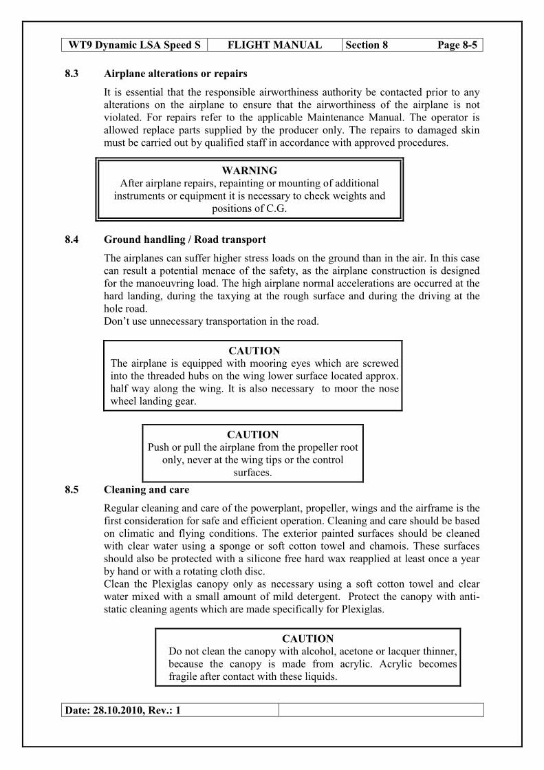
WT9 Dynamic LSA Speed S FLIGHT MANUAL Section 8 Page 8-5
8.3 Airplane alterations or repairs
It is essential that the responsible airworthiness authority be contacted prior to any
alterations on the airplane to ensure that the airworthiness of the airplane is not
violated. For repairs refer to the applicable Maintenance Manual. The operator is
allowed replace parts supplied by the producer only. The repairs to damaged skin
must be carried out by qualified staff in accordance with approved procedures.
WARNING
After airplane repairs, repainting or mounting of additional
instruments or equipment it is necessary to check weights and
positions of C.G.
8.4 Ground handling / Road transport
The airplanes can suffer higher stress loads on the ground than in the air. In this case
can result a potential menace of the safety, as the airplane construction is designed
for the manoeuvring load. The high airplane normal accelerations are occurred at the
hard landing, during the taxying at the rough surface and during the driving at the
hole road.
Don’t use unnecessary transportation in the road.
CAUTION
The airplane is equipped with mooring eyes which are screwed
into the threaded hubs on the wing lower surface located approx.
half way along the wing. It is also necessary to moor the nose
wheel landing gear.
CAUTION
Push or pull the airplane from the propeller root
only, never at the wing tips or the control
surfaces.
8.5 Cleaning and care
Regular cleaning and care of the powerplant, propeller, wings and the airframe is the
first consideration for safe and efficient operation. Cleaning and care should be based
on climatic and flying conditions. The exterior painted surfaces should be cleaned
with clear water using a sponge or soft cotton towel and chamois. These surfaces
should also be protected with a silicone free hard wax reapplied at least once a year
by hand or with a rotating cloth disc.
Clean the Plexiglas canopy only as necessary using a soft cotton towel and clear
water mixed with a small amount of mild detergent. Protect the canopy with anti-
static cleaning agents which are made specifically for Plexiglas.
CAUTION
Do not clean the canopy with alcohol, acetone or lacquer thinner,
because the canopy is made from acrylic. Acrylic becomes
fragile after contact with these liquids.
Date: 28.10.2010, Rev.: 1

8.6 Winter operation
The cooling system of the cylinder heads is filled with a mixture of anti-freeze and
water, which protects the cooling system against freezing up to – 38 ° C. Check
coolant with densimeter or glycol tester before winter operation and to prevent the
failure of the radiator or cooling system due ice.
If the temperature is below this value, the coolant must be drained or renewed with
pure anti-freeze liquid. The coolant must be renewed every two years. Use only
coolant according to the current Operator’s Manual for engine ROTAX 912 ULS.
If low cylinder head or oil temperatures occur during operation under low outside
temperature, then the following is recommended:
Cover a part of radiator face by a duralumin sheet or drawing paper of appropriate
dimensions, insert it between the radiator and the bottom engine cowling.
Cover the oil cooler face or a part of the face only, by a duralumin sheet or drawing
paper attached with a suitable adhesive tape ( or bend the oil cooler with that tape )
and lag the oil tank.
CAUTION
The temperature limits of the coolant, cylinder heads and oil
must be checked after these arrangements.
If the airplane has a fixed undercarriage with wheel spats fitted it is recommended
that these should be removed during winter operations on frozen or rough ground to
minimize damage to the spats.
I winter operation is
advisable to
disconnect the
ventilation intake hose
(VIH) due the better
performance of
heating system. After
disconnecting the
ventilation intake hose
close the socket for the
hose. Otherwise the
ram air will be loosen
by this opening.
WT9 Dynamic LSA Speed S FLIGHT MANUAL Section 8 Page 8-6
Date: 28.10.2010, Rev.: 1
VIH
WT9 Dynamic LSA Speed S FLIGHT MANUAL Section 9 Page 9-1
SECTION 9
SUPPLEMENTS
Page
9.1 Introduction 9-1
9.2 List of inserted supplements 9-1
9.3 Supplements inserted 9-2
9.4 Payload range diagrams 9-2
9.5 Placards 9-4
9.6 ELT AK-451 9-5
9.7 Rescue Parachute System 9-6
9.8 Dynamic Board Computer 9-10
9.9 Garmin SL 30, SL 40 9-11
9.10 Garmin GMA240 Audio Panel 9-13
9.11 Garmin GTX328 Transponder 9-14
9.1 Introduction
This section contains the appropriate supplements necessary to safely and efficiently
operate the airplane when equipped with various optional systems and equipment not
provided with the standard airplane.
NOTE
Additional individual equipment in accordance with a
customer’s request will increase the airplane empty
weight and reduce the allowed useful load.
9.2 List of inserted supplements
Date Doc. No. Title of the inserted supplement
28.10.2010
DYNON Avionics SkyView system (2x10´´ display,
2xADHARS, 2xGPS, EMS)
ELT AK-451
Rescue Parachute system Magnum 601
Dynamic Board computer
Garmin SL 30, SL 40 Com/Nav Radios
Garmin GMA 240 Audio Panel
Garmin GTX 328 Transponder
Date: 14.06.2011, Rev.: 2

WT9 Dynamic LSA Speed S FLIGHT MANUAL Section 9 Page 9-2
9.3 Supplements inserted
For operation and handling with Dynon Avionic’s SkyView System consult
corresponding Operation manual. For other inserted supplements see respective
chapters of this section (Section 9)
9.4 Payload range diagrams
19,00
20,00
21,00
22,00
23,00
24,00
25,00
26,00
27,00
28,00
29,00
30,00
31,00
0 10 20 30 40 50 60 70 80 90 100110120130140150160170180190200210220230
C.
G.
(% M
AC
)
Crew weight (kg)
C. G. possition for 0 kg baggage
C. G. at max. allowed fuel amount C. G. after the fuel is consumed
Limit front C. G. Limit aft C. G.
Date: 14.06.2011, Rev.: 2
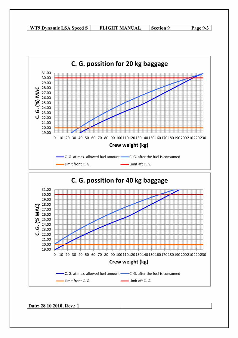
WT9 Dynamic LSA Speed S FLIGHT MANUAL Section 9 Page 9-3
Date: 28.10.2010, Rev.: 1
19,00
20,00
21,00
22,00
23,00
24,00
25,00
26,00
27,00
28,00
29,00
30,00
31,00
0 10 20 30 40 50 60 70 80 90 100110120130140150160170180190200210220230
C.
G.
(%)
MA
C
Crew weight (kg)
C. G. possition for 20 kg baggage
C. G. at max. allowed fuel amount C. G. after the fuel is consumed
Limit front C. G. Limit aft C. G.
19,00
20,00
21,00
22,00
23,00
24,00
25,00
26,00
27,00
28,00
29,00
30,00
31,00
0 10 20 30 40 50 60 70 80 90 100110120130140150160170180190200210220230
C.
G.
(% M
AC
)
Crew weight (kg)
C. G. possition for 40 kg baggage
C. G. at max. allowed fuel amount C. G. after the fuel is consumed
Limit front C. G. Limit aft C. G.

WT9 Dynamic LSA Speed S FLIGHT MANUAL Section 9 Page 9-4
9.5 Placards
Elevator, Rudder, Ailerons
Wing, adjacent to fuel filler caps
Engine cowling close oil filler access
Right wing, Flaps aft edge
Both sides of fuselage close to static vent
Date: 14.06.2011, Rev.: 2
NO PUSH
FUEL EUROSUPER 95
MAX. 63 l
NO STEP
STATIC VENT KEEP CLEAN
OIL MOBIL 1 RACING 4T
MAX 3,0 l

WT9 Dynamic LSA Speed S FLIGHT MANUAL Section 9 Page 9-5
9.6 ELT AK-451 Quick Guide
The ELT switch on the Main Unit should be left at ARM position and the ELT is ready to go.
Note 1: The ELT switch is “make before break.” Return to OFF for at least 1 sec before
changing positions.
Note 2: Press RESET anytime to turn off unwanted transmission.
Date: 14.06.2011, Rev.: 2
LEDs
(Main Unit + Remote Unit) Buzzer Sound
Swept tone on 121.5 MHz VHF Radio
1. ELT switch at ON
position
4 sec off On continuously
1 sec on
2. ELT switch at ARM
position 4 sec on None
3. ELT switch at ARM
position for another 25 sec
(Self Test Mode) Self Test takes 25 sec
None
NOTE: If the LEDs flash there is a problem. Please refer to “Installation and Operation manual” paragraph 2.4 for details.
4. ELT switch at ARM
position. Shake ELT hard Forward and Backward
(G Switch Test)
4 sec off
On continuously 1 sec on
5. Press RESET button on Main Unit
None
6. Press ON button on Remote Unit
4 sec off On continuously
1 sec on
7. Press RESET button on Remote Unit
None

WT9 Dynamic LSA Speed S FLIGHT MANUAL Section 9 Page 9-6
9.7 Rescue parachute System
1. Operations before the flight
1) The control of the rescue system anchorage incl. the rocket and the activation handle
2) The control of the cable anchorage to the aircraft, it must be not slack
3) If nothing does prevent the parachute to be smoothly pulled out of the aircraft
4) To unlock the activation handle.
2. How and when to activate the rescue system
A) In critical situations activate the rescue system immediately regardless to the flight altitude
and terrain character over which you are ( e.g. an unavoidable collision resolve by the
activation of the system MAGNUM as soon as possible, in the moment before it comes –
sufficiently ahead of it!)
B) Ideal action:
1. Switch off the ignition
2. Strongly pull the activation handle
3. Protect with the hands your face, the hands and feet together (the position „roll into a
ball“), firm up the whole body!
ATTENTION! It is necessary to fix oneself in this position especially:
a) by the opening of the parachute!
b) by the landing!
4. After the parachute opening shut up the fuel pipe(if there is enough time for it)
5. Before the shock fasten the safety belt!
C) In the case of really extreme distress pull at first the activation handle and then
immediately switch off the ignition and the fuel pipe.
D) The right operations is necessary to train in beforehand.
Date: 14.06.2011, Rev.: 2

WT9 Dynamic LSA Speed S FLIGHT MANUAL Section 9 Page 9-7
3. How does perceive the crew the activating process
After the activation is heard the rocket motor ignition followed by the sound of leaking
gasesby the motor nozzle. After it comes gradual retarding of the movement ending by a
gentle pulling. It shows that the parachute is loaded. There may follow several swings with a
stabilization trend. (Everything depends on the situation, circumstances of the proceeding
rescue, on the position and on the altitude. By the activation in a larger altitude you have got a
larger chance for the stabilization of the swings and for a smooth landing on the earth.)
The touch with the earth should be such as if you would be unsuccessful by a smooth landing.
It depends on the character of the terrain where you are landing.
Stopping of the motor is important in order to prevent the conflict of the suspension cable
with the rotating propeller and this especially by aircraft with the propeller in pushing
arrangement.
Closing of the fuel feed is necessary to prevent a start of the fire!
! A vital notice: When you pull the activation handle it begins with a lesser resistance. The
handle gets loose from the safety position fixed by a flexible picket. It follows a free
approximately 5cm long going of the safety cable. Then grows slowly the resistance by the
influence of the starting spring stretching. In the moment, when the spring is maximally
compressed, gets the percussive device in the upper position loose and strikes two percussion
caps, that activate the rocket motor of the rescue system.
4 How to behave after the landing
1) It is necessary to leave the aircraft without delay and this with regard to the health of the
crew – possible injuries.
-reasons:
a) in windy weather may the loaded parachute be the cause of aircraft dragging. (by pulling
of several parachute lines, that are beside one another pours the parachute out and gets calm)
b) after a harder landing, when e.g. the landing did not happen on the pandiny gear, may start
a fault, may come to the fuel tank damage and to the fire danger.
Attention!
Date: 14.06.2011, Rev.: 2

WT9 Dynamic LSA Speed S FLIGHT MANUAL Section 9 Page 9-8
a) after the landing on a hill side always step out in the direction up the hill!
b) after a landing on an electric line neither do touch further wires nor step out on the earth.
Call for help, secure the switch off of the electric current on the line and then you may come
down!
5 How large powers do influence the aircraft and the crew after the development of the
parachute.
In maximal speed, for which are the parachutes designed, may the short-time overload get till
the value of 5G. Therefore every point, where are fastened the guy cables into the aircraft,
must have the minimum strength of 5G! Use only cables and snap hooks delivered by the
producer, or recommended by him!
The aircraft should be hanged on the parachute so as to fall to the ground, after the touch with
the earth, on the wheels of the landing gear, because they will soften the fall. Appropriate is
the position to be moderately inclined forwards, because of the stabilization during the
descent on the parachute. This reality is necessary to regard with the choice of the length of
suspending cable harness.
6 Situations in which it is possible to use successfully the rescue system
a)Engine failure over a terrain, where it is not possible to land safely from the gliding
flight.
Do not hesitate and activate the rescue system in time with the regard to the safe stabilization
and so that the meeting with the earth would come after calming of the swings. Do not
hesitate with the activation in cases when you are not sure, that you will overcome some
obstacle by the gliding flight, or that you will not surely reach the area chosen for the landing!
b) Loss of orientation
1) In good weather is the fuel at the end and in the reach is no appropriate area for emergency
landing
2) Sudden worsening of weather conditions when during the flight VFR is the visibility
reduced under an acceptable limit and it could come to a collision with an obstacle.
Date: 14.06.2011, Rev.: 2

WT9 Dynamic LSA Speed S FLIGHT MANUAL Section 9 Page 9-9
3) Loss of the notion of the aircraft flight position. It may come after the flying into a cloud or
the fog. The situation of sudden worsening of meteorological conditions.
In these situations activate your rescue system immediately!!!
Be careful in situations, when you are in a strong updraft. In these cases you must at first get
out of it and then use the rescue system.
c)Short landing path
If there‘s no way out and if there threatens on the end of the path some obstacle and the flying
up is not possible or safe, you may activate the rescue system in the ground flight near over
the earth approximately max. till 1m. But it is necessary to go on in the landing after the firing
of the rescue system and to become the aircraft quickly to the earth. In such a situation begins
the parachute to brake in the moment, when the wheels touch the earth.
d)Mechanical defect
If a mechanical defect makes impossible the aircraft control or safe landing, there is a reason
for the activation of the rescue system MAGNUM. If it is possible choose a propriate terrain
for the parachute landing with regard to the high voltage line, the buiding development, the
wood, the wind direction, etc.
e)Collision during the flight
Activate your rescue system if possible in the time before it inevitably comes! Here it applies,
the earlier you react, the higher will be the chance for rescuing your life! Fractions of asecond
may decide!
f)Piloting control mistake
To dangerous piloting control mistakes, that may you endanger, comes mostly in small
altitudes. The loss of speed, the corcscrew spin, the fall down plane etc.
In such situations you have to react without delay! Even from a small altitude you have a
chance to be rescued!
Date: 14.06.2011, Rev.: 2

WT9 Dynamic LSA Speed S FLIGHT MANUAL Section 9 Page 9-10
Remember, that even a piloting control mistake in a larger altitude may be for you dangerous.
Such a transit from a corcscrew spin to a spiral and a spiral itself may be for you dangerous
by the sharp speed rise to such a limit, that your rescue system could be inefficient. The
altitude lessens in such situations very quickly. Activate therefore your rescue system as soon
as possible!
g)Pilots disability to control the aircraft
It may be health problems as heart attack, injury of the pilot, loss of consciousness ... If it is
possible he may activate the rescue system by himself, or his fellow passenger, who must be
informed of the rescue system function and use before the flight!
h)Fire on the aircraft deck
It is important to stop the oxygen supply to the flame and also of the material which burns, it
is of the fuel. In case you can not immediatelly safely land, activate the rescue system. So you
can come on the earth and from the reach of the flames more quick. In case, that it burns in
the area of the motor space, or somewhere after the fuel-lock on the line to the motor, lock the
fuel supply, let the motor run, open the supply of the mixture feed (open the throttle) to
consume the fuel from its line and to stop the burning!
Even because of such situations are favourable cables of steel or of Kevlar. These materials
resist the flames more, than e.g. cables on the base of nylon, etc...
Date: 14.06.2011, Rev.: 2

WT9 Dynamic LSA Speed S FLIGHT MANUAL Section 9 Page 9-11
9.8 Dynamic Board Computer
This computer is standard PC, based on Intel CPU, usually running Microsoft Windows
operation system, but can also be running other platforms like Linux and so on. The computer
is constructed to perform in such conditions like turbulence and hi/low temperatures. For that
reason there no mechanical moving parts but fans. Standard hard drive is substituted with a
solid state disk. Technical specification like memory size, SSD size, CPU performance is
subject to individual wishes of the customer.
System sustains from:
• Main computer unit of special design in aluminum case located behind baggage
compartment
• 7” wide screen LCD touch screen located on a dashboard
• Additional pointing device (trackball) located on horizontal center panel just beside
the throttle lever.
• Independent GPS module providing current GPS location of the aircraft this can be
used by any custom applications running on the PC eventually.
• Wireless Bluetooth keyboard powered form battery and can be recharged from any
USB interface.
To power on the computer, switch on the “ PC ” switch. It’s third switch from left from set of
electric control switches located below left MFD. It takes approximately 5 sec. to start power-
on process. If the computer will not start, check if both circuit breakers “PC PWR” and ”PC
CTRL” are in. If the circuit breakers are in proper position and computer still will not start,
please contact service.
To shut down the PC, switch off the “ PC ” switch. This will start the shut down sequence
(closing all running applications and operation system). It may take some time to power off
the system.
User’s guides and manuals of individual applications running on the PC are usually in a form
of online help within these applications and programs.
There are also 4 standard USB interfaces in the cabin of the aircraft. Two of them are located
on a dashboard and the rest two are located on back wall of baggage compartment. These
USB ports can be used for connecting to any standard USB devices, like USB flash sticks,
USB CD-ROM drive, USB Wi-Fi dongle ….
PC also have a stereo audio output which is connected into “Music 2” input of a Garmin
GMA240 audio panel located just below the 7” LCD touch screen. This provides hi-fidelity
stereo sound directly into your headsets and is intended for multimedia use. Please consult
Garmin GMA240 audio panel manual for managing the audio.
NOTE: IT’S RECOMMENDED TO CHECK FOR UPDATES OF OPERATION SYSTEM
AND PROGRAMS INSTALLED ON THE PC TO ASSURE OPTIMAL PERFORMANCE
AND RELIABILITY.
Date: 14.06.2011, Rev.: 2

WT9 Dynamic LSA Speed S FLIGHT MANUAL Section 9 Page 9-12
9.9 Garmin SL 30, SL 40 Quick Guide
Date: 14.06.2011, Rev.: 2

WT9 Dynamic LSA Speed S FLIGHT MANUAL Section 9 Page 9-13
Date: 14.06.2011, Rev.: 2

WT9 Dynamic LSA Speed S FLIGHT MANUAL Section 9 Page 9-14
9.10 Garmin GMA240 Audio Panel Quick Guide
Volume/Squelch: Rotating the Pilot Volume Knob (left small knob)
controls the ON and OFF function (Full CCW detent is OFF). The
large left knob controls Pilot squelch.
Pulling the right volume knob (small knob) controls music volume,
pushing in controls Copilot and passenger volume. The large right
knob controls Copilot and passenger squelch.
Date: 14.06.2011, Rev.: 2

WT9 Dynamic LSA Speed S FLIGHT MANUAL Section 9 Page 9-15
9.11 Garmin GTX328 Transponder Quick Guide
The GTX 328 transponder is powered on by pressing the STBY, ALT or ON keys, or by a
remote avionics master
switch (if applicable). After power on, a start-up page is displayed while the unit performs a
self test.
Mode Selection Keys
OFF - Powers off the GTX 328. Pressing STBY, ON or ALT Key powers on the transponder
displaying the last active identification code.
STBY - Selects the standby mode. When in standby mode, the transponder will not reply to
any interrogations.
ON - Selects Mode A. In this mode, the transponder replies to interrogations, as indicated by
the Reply Symbol ( ). Replies do not include altitude information.
ALT - Selects Mode A and Mode C. In ALT mode, the transponder replies to identification
and altitude interrogations as indicated by the Reply Symbol ( ). Replies to altitude
interrogations include the standard pressure altitude received from an external altitude source,
which is not adjusted for barometric pressure. The ALT mode may be selected in aircraft not
equipped with an optional altitude encoder; however, the reply signal will not include altitude
information.
Any time the function ON or ALT is selected the transponder becomes an active part of the
Air Traffic Control Radar Beacon System (ATCRBS). The transponder also responds to
interrogations from TCAS equipped aircraft.
Code Selection
Code selection is done with eight keys (0 – 7) providing 4,096 active identification codes.
Date: 14.06.2011, Rev.: 2

WT9 Dynamic LSA Speed S FLIGHT MANUAL Section 9 Page 9-16
Pushing one of these keys begins the code selection sequence. Digits that are not yet entered
appear as dashes. The new code is activated when the fourth digit is entered. Pressing the
CLR Key moves the cursor back to the previous digit. Pressing the CLR Key when the
cursor is on the first digit of the code, or pressing the CRSR Key during code entry, removes
the cursor and cancels data entry, restoring the previous code. Press the CLR Key up to five
seconds after code entry is complete to return the cursor to the fourth digit. The numbers 8
and 9 are not used for code entry, only for entering a Count Down time, and contrast and
display brightness.
Important Codes:
1200 - The VFR code for any altitude in the US (Refer to ICAO standards elsewhere)
7000 - The VFR code commonly used in Europe (Refer to ICAO standards)
7500 - Hijack code (Aircraft is subject to unlawful interference)
7600 - Loss of communications
7700 - Emergency
7777 - Military interceptor operations (Never squawk this code)
0000 - Military use
Avoid selecting codes 0000, 7500, and all codes in the 7600-7777 range. These codes trigger
special indicators in automated facilities. An aircraft’s transponder code is used for ATC
tracking purposes, therefore exercise care when making routine code changes!
Keys for Other GTX 328 Functions
IDENT - Pressing the IDENT Key activates the Special Position Identification (SPI) Pulse
for 18 seconds, identifying your transponder return from others on the air traffic controller’s
screen. The word ‘IDENT’ will appear in the upper left corner of the display while the
IDENT mode is active.
VFR - Sets the transponder code to the pre-programmed VFR code selected in Configuration
Mode (this is set to 7000 at the factory). Pressing the VFR Key again restores the previous
identification code. If the VFR Key is disabled (dependent upon installation configuration) a
‘VFR Key Disabled’
message appears, to indicate that no operation took place.
FUNC - Changes the page shown on the right side of the display. Display data includes
Pressure Altitude, Flight Time, Altitude Monitor, Count Up and Count Down timers. Also
displays Outside Air Temperature, Density Altitude, Contrast, and Display (dependent upon
installation configuration).
Date: 14.06.2011, Rev.: 2

WT9 Dynamic LSA Speed S FLIGHT MANUAL Section 9 Page 9-17
START/STOP - Starts and stops the Altitude Monitor, Count Up, Count Down and Flight
timers.
CRSR - Initiates starting time entry for the Count Down timer and cancels transponder code
entry.
CLR - Resets the Count Up, Count Down and Flight timers. Cancels the previous keypress
during code selection and Count Down entry. Returns cursor to the fourth code digit within
five seconds after entry.
8 - Reduces Contrast and Display Brightness when the respective fields are displayed
(dependent upon installation configuration) and enters the number eight into the Count Down
timer.
9 - Increases Contrast and Display Brightness when the respective fields are displayed
(dependent upon installation configuration) and enters the number nine into the Count Down
timer.
Function Display
PRESSURE ALT - Displays the altitude data supplied to the GTX 328 in feet,
hundreds of feet (i.e., flight level), or meters, (dependent upon installation
configuration.
FLIGHT TIME - Timer start is configured as either Manual or Automatic.
When Manual, displays the Flight Time, controlled by the START/STOP and
CLR keys. When Automatic, the timer begins when take off is sensed.
ALTITUDE MONITOR - Controlled by START/STOP Key. Activates a
voice alarm and warning annunciator when altitude limit is exceeded.
OAT/DALT - Displayed when the GTX 328 is configured with temperature
input. Displays Outside Air Temperature and Density Altitude.
COUNT UP TIMER - Controlled by START/STOP and CLR keys.
COUNT DOWN TIMER - Controlled by START/STOP, CLR, and CRSR
keys. The initial Count Down time is entered with the 0 – 9 keys.
CONTRAST - This page is only displayed if manual contrast mode is selected
during installation configuration. Contrast is controlled by the 8 and 9 keys.
DISPLAY - This page is only displayed if manual backlighting mode is selected during
installation configuration. Backlighting is controlled by the 8 and 9
keys.
Date: 14.06.2011, Rev.: 2

WT9 Dynamic LSA Speed S FLIGHT MANUAL Section 9 Page 9-18
Altitude Trend Indicator
When the ‘PRESSURE ALT’ page is displayed, an arrow may be displayed to the right of the
altitude, indicating that the altitude is increasing or decreasing. One of two sizes of arrows
may be displayed depending on the vertical speed rate. The sensitivity of these arrows is set
by an authorized Garmin Aviation Service Center.
The GTX 328’s options are normally set at time of installation. To request any changes of the
GTX 328 parameters, contact an authorized Garmin Aviation Service Center.
Mode S Data Transmission
In addition to 4096 code and pressure altitude, the GTX 328 is capable of transmitting aircraft
identification, transponder capability and maximum speed range. “Aircraft Identification” is
commonly referred to as FLT ID (Flight Identification). The GTX 328 may be configured by
the installer to allow the flight crew to enter FLT ID for each flight. An example is when air-
carrier service requires changing the FLT ID.
The FLT ID may consist of the aircraft registration or a flight number as agreed upon with
the local aviation authority. In either case, the FLT ID must be the same aircraft identification
that appears in the flight plan to correlate the aircraft identification seen on ATC radar with
the correct voice call sign for the aircraft. If no flight plan is filed with the aviation authority
(as may be permitted by regulations), the FLT ID entered is the aircraft registration marking.
When flight crew entry of the FLT ID is not required, the installer configures the system to
report the aircraft identification according to local aviation requirements. In this
configuration, alteration of the FLT ID by the flight crew is not possible.
Audio Alerts
(Setting options; male/female voice or tone, and volume level.)
• “Leaving Altitude” Altitude deviation is exceeded.
• “Timer Expired” for countdown time.
Date: 14.06.2011, Rev.: 2