Embed Size (px)
Citation preview

G) Allen-Bradley Technical Data
Micrologix 1200 Programmable Controllers
Bulletin 1762
www . El
ectric
alPar
tMan
uals
. com
2 Micrologix 1200 Programmable Controllers
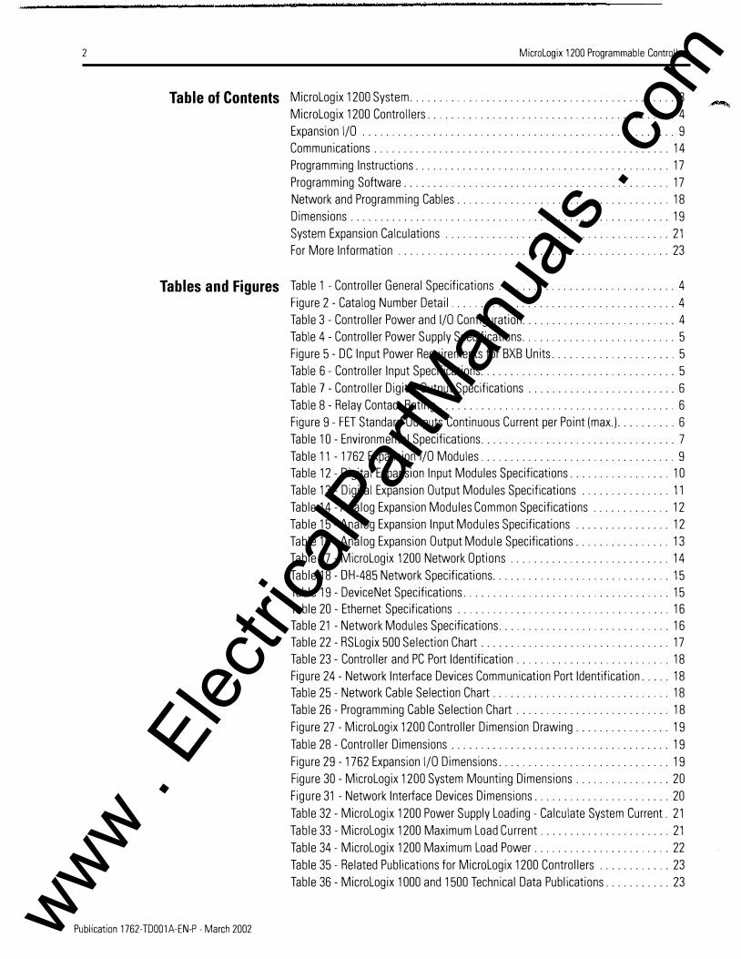
Table of Contents Micrologix 1200 System . . . . . . . . . . . . . . . . . . . . . . . . . . . . . . . . . . . . . . . . . . . . . 3 Micrologix 1200 Controllers . . . . . . . . . . . . . . . . . . . . . . . . . . . . . . . . . . . . . . . . . . 4 Expansion l/0 . . . . . . . . . . . . . . . . . . . . . . . . . . . . . . . . . . . . . . . . . . . . . . . . . . . . . 9 Communications . . . . . . . . . . . . . . . . . . . . . . . . . . . . . . . . . . . . . . . . . . . . . . . . . . 14 Programming Instructions . . . . . . . . . . . . . . . . . . . . . . . . . . . . . . . . . . . . . . . . . . . 17 Programming Software . . . . . . . . . . . . . . . . . . . . . . . . . . . . . . . . . . . . . . . . . . . . . 17 Network and Programming Cables . . . . . . . . . . . . . . . . . . . . . . . . . . . . . . . . . . . . 18 Dimensions . . . . . . . . . . . . . . . . . . . . . . . . . . . . . . . . . . . . . . . . . . . . . . . . . . . . . . 19 System Expansion Calculations . . . . . . . . . . . . . . . . . . . . . . . . . . . . . . . . . . . . . . 21 For More Information . . . . . . . . . . . . . . . . . . . . . . . . . . . . . . . . . . . . . . . . . . . . . . 23
Tables and Figures Table 1 -Controller General Specifications . . . . . . . . . . . . . . . . . . . . . . . . . . . . . . 4 Figure 2 - Catalog Number Detail . . . . . . . . . . . . . . . . . . . . . . . . . . . . . . . . . . . . . . 4 Table 3 - Controller Power and 1/0 Configuration . . . . . . . . . . . . . . . . . . . . . . . . . . 4 Table 4- Controller Power Supply Specifications . . . . . . . . . . . . . . . . . . . . . . . . . . 5 Figure 5- DC Input Power Requirements for BXB Units . . . . . . . . . . . . . . . . . . . . . 5 Table 6- Controller Input Specifications . . . . . . . . . . . . . . . . . . . . . . . . . . . . . . . . . 5 Table 7- Controller Digital Output Specifications . . . . . . . . . . . . . . . . . . . . . . . . . 6 Table 8- Relay Contact Rating . . . . . . . . . . . . . . . . . . . . . . . . . . . . . . . . . . . . . . . . 6 Figure 9- FET Standard Outputs Continuous Current per Point (max.) . . . . . . . . . . 6 Table 10- Environmental Specifications . . . . . . . . . . . . . . . . . . . . . . . . . . . . . . . . . 7 Table 11 - 1762 Expansion 1/0 Modules . . . . . . . . . . . . . . . . . . . . . . . . . . . . . . . . . 9 Table 12- Digital Expansion Input Modules Specifications . . . . . . . . . . . . . . . . . 10 Table 13- Digital Expansion Output Modules Specifications . . . . . . . . . . . . . . . 11 Table 14- Analog Expansion Modules Common Specifications . . . . . . . . . . . . . 12 Table 15- Analog Expansion Input Modules Specifications . . . . . . . . . . . . . . . . 12 Table 16- Analog Expansion Output Module Specifications . . . . . . . . . . . . . . . . 13 Table 17- Micrologix 1200 Network Options . . . . . . . . . . . . . . . . . . . . . . . . . . . 14 Table 18- DH-485 Network Specifications . . . . . . . . . . . . . . . . . . . . . . . . . . . . . . 15 Table 19- DeviceNet Specifications . . . . . . . . . . . . . . . . . . . . . . . . . . . . . . . . . . . 15 Table 20 - Ethernet Specifications . . . . . . . . . . . . . . . . . . . . . . . . . . . . . . . . . . . . 16 Table 21 - Network Modules Specifications . . . . . . . . . . . . . . . . . . . . . . . . . . . . . 16 Table 22 - RSLogix 500 Selection Chart . . . . . . . . . . . . . . . . . . . . . . . . . . . . . . . . 17 Table 23- Controller and PC Port Identification . . . . . . . . . . . . . . . . . . . . . . . . . . 18 Figure 24- Network Interface Devices Communication Port Identification . . . . . 18 Table 25- Network Cable Selection Chart . . . . . . . . . . . . . . . . . . . . . . . . . . . . . . 18 Table 26- Programming Cable Selection Chart . . . . . . . . . . . . . . . . . . . . . . . . . . 18 Figure 27 - Micrologix 1200 Controller Dimension Drawing . . . . . . . . . . . . . . . . 19 Table 28- Controller Dimensions . . . . . . . . . . . . . . . . . . . . . . . . . . . . . . . . . . . . . 19 Figure 29- 1762 Expansion l/0 Dimensions . . . . . . . . . . . . . . . . . . . . . . . . . . . . . 19 Figure 30 - Micrologix 1200 System Mounting Dimensions . . . . . . . . . . . . . . . . 20 Figure 31 -Network Interface Devices Dimensions . . . . . . . . . . . . . . . . . . . . . . . 20 Table 32- MicroLogix 1200 Power Supply Loading- Calculate System Current. 21 Table 33- MicroLogix 1200 Maximum Load Current . . . . . . . . . . . . . . . . . . . . . . 21 Table 34- MicroLogix 1200 Maximum Load Power . . . . . . . . . . . . . . . . . . . . . . . 22 Table 35- Related Publications for MicroLogix 1200 Controllers . . . . . . . . . . . . 23 Table 36- MicroLogix 1000 and 1500 Technical Data Publications . . . . . . . . . . . 23
Publication 1 762-TD001A-EN-P- March 2002 www . El
ectric
alPar
tMan
uals
. com

Micrologix 1200 System
Micrologix 1200 System MicroLogix 1200 controllers provide the computing power and flexibility to solve a variety of applications utilizing the proven �1icroLogix and SLC family architecture.
Available in 24 and 40-point versions, the I/0 count can be expanded using rackless I/0 modules resulting in lower system cost and
reduced parts inventory.
A field-upgradable flash operating system ensures you will always be up-to-date with the latest features, without having to replace
hardware. The controller can be easily updated with the latest
firmware via a web site download.
The �1icroLogix 1200 controller utilizes Rockwell Software RSLogix 500 programming software and shares a common instruction set with
the :tvficroLogix 1000, :tvficroLogix 1500 and SLC families of controllers.
Advantages
• Large 6K memory to solve a variety of applications
• Field-upgradable flash operating system
• High performance expansion I/0 options (up to 6 modules depending on power budget)
• Advanced communications options including peer-to-peer and SCADA/RTU networks, DH-485, DeviceNet, and Ethernet
• Communications toggle push button
• Data file download protection prevents critical user data from being altered via communications
• Two built-in analog trim potentiometers
• Optional real-time clock
• Optional memory module
• 20 kHz high-speed counter, featuring 8 modes of operation
• One high-speed output that can be configured as 20 kHz PTO (Pulse Train Output) or as PWM (Pulse Width Modulated) outputs
• Four high-speed latching (pulse-catch) inputs
• 32-bit signed integer math
• Floating point data file
• Built-in PID capabilities
• ASCII read/write capability
• Four event interrupt inputs (Ell)
• 1 ms high-resolution timers
• 1 ms selectable timed interrupt (STI)
• Finger-safe terminal blocks meet global safety standards
• Removable terminal blocks on 40-point controllers allow pre-wmng
• Regulatory agency certifications for world-wide market (CE, C-Tick, UL, c-UL, including Class I Division 2 Hazardous Location)
3
Micrologix 1 200 Programmable Controllers Technical Data Publication 1762-TD001 A-EN-P - March 2002 www . El
ectric
alPar
tMan
uals
. com

4
Micrologix 1200 Controllers
Micrologix 1 2DD Controllers
Controller Specifications
The following tables summarize the specifications for MicroLogix 1200
controllers.
Table 1 Controller General Specifications
Specification All1762 Controllers Memory Size and Type 6K flash memory: 4K user program. 2K user data
Data Elements configurable, user-defined file structure, 2K max. data size
Throughput ;> ms (for a typical 1 K word user program)111
(1) A typ1cal user progra m contains b1t, t1mer, counter, math and f1le mstruct1ons.
Figure 2 Catalog Number Detail
1762 - L 24 A W A
Bulletin Number _j Base Unit ---....:
Number of 1/0 ----.J
Input Type: ------'
A= 12DV ac B = 24V de
Table 3 Controller Power and 1/0 Configuration
Line Power Inp uts Outputs 1 2D/24DV ac (14) 12DVac (1D) Relay
1 2D/24DV ac (24) 12DV ac (16) Relay
1 2D/24DV ac (1 D) Standard 24V de (1D) Relay (4) Fast 24V de
1 2D/24DV ac (2D) Standard 24V de (16) Relay (4) Fast 24V de
24V de (1 D) Standard 24V de (5) Relay (4) Fast 24V de (4) Standard 24V de FET
( 1 I Fast 24V de FET
24V de (2D) Standard 24V de (8) Relay (4) Fast 24V de (7) Standard 24V de FET
(1 I Fast 24V de FET
.__----Power Supply A= 1 2D/24DV ac B = 24V de
'-------- Output Type: W= Relay X= Relay/24V de FET
Hig h Speed 1/0 Catalog Number n/a 1 762-L24AWA
n/a 1762-L4DAWA
(4) 2D kHz input 1762-L24BWA
(4) 2D kHz input 1 762-L4DBWA
(4) 2D kHz input 1762-L24BXB ( 1 I 2D kHz output
(4) 2D kHz input 1762-L4DBXB ( 1 I 2D kHz output
Publication 1 762-TDDD1 A-EN-P- March 2DD2 Micrologix 12DD Programmable Controllers Technical Data www . El
ectric
alPar
tMan
uals
. com

MicroLogix 1200 Controllers 5
Table 4 Controller Power Supply Specifications
Specif ication 1762-L24AWA L40AWA L24BWA L40BWA L24BXB L 40BXB
Power Supply Voltage 85 to 265V ac at 47 to 63 Hz 20.4 to 26.4V de Class 2 SELV
Power Consumption 68 VA 80VA 70 VA 82 VA 27W 40W
Power Supply Inrush 1 20V ac: 25A for 8 ms 24V de: 24V de: Current (max.) 240V ac: 40A for 4 ms 1 5A for 20 ms 15A for 30 ms
Maximum Load 5V de 400 mA 600 mA 400 mA 600 mA 400 mA 600 mA Current111 24V de 350 mA 500 mA 350 mA 500 mA 350 mA 500 mA
Maximum Load Power 1 0.4W 15W 12W 1 6W 10.4W 15W
24V de Sensor Power n/a n/a 250 mA, 400 �F 400 mA. 400 �F n/a n/a capacitance max. capacitance max.
(1) See System Expansion Calculations on page 21 for an exa mple system val1dat1on worksheet to calculate expansion 1!0 power usage.
Figure 5 DC Input Power Requirements for BXB Units
1762-L24BXB Typical Power Requirements
Calculated Load Power (Watts)
Table 6 Controller Input Specifications
Specif ication 1762-L24AWA 1762-L 40AWA
On-State Voltage Range 79 to 1 32V ac 47 Hz to 63 Hz
Ott-State Voltage Range 0 to 20V ac
Operating Frequency n/a
Signal Delay (max.) ON Delay= 20 ms OFF Delay= 20 ms
On-State Current: Minimum 5.0 mA at 79V ac Nominal 12 mA at 1 20V ac Maximum 1 6.0 mA at 132V ac
Off-State Leak age Current (max.) 2.5 mA max.
Nominal Impedance 12K Qat 50 Hz 10K nat 60 Hz
Maximum Inrush Current 250 mA at 120V ac
MicroLogix 1 200 Programmable Controllers Technical Data
30
'iii 25 ...
. ; i 20 i� 15 ; � 10 &:fC:S l 5
1762-L40BXB Typical Power Requirements
10 Calculated Load Power (Watts)
1762-L24BWA. -L24BXB. -L 40BWA. -L 40BXB Inputs 0 throug h 3 Inputs 4 and hig her
12
1 4 to 26.4V de at 55°C (1 31°F) 10 to 26.4V de at 55°C (1 31 °F) 14 to 30.0V de at 30°C (86°F) 1 0 to 30.0V de at 30°C (86°F)
0 to 5V de
0 Hz to 20 kHz 0 Hz to 1 k Hz (scan time dependent)
standard inputs: selectable from 0.5 to 16 ms high-speed inputs: selectable from 0.025 to 1 6 ms
2.5 mA at 1 4V de 2.0 mA at 10V de 7.3 mA at 24V de 8.9 mA at 24V de 1 2.0 mA at 30V de 12.0 mA at 30V de
1 .5 mA min.
3.3K n 2.7K Q
n/a
14
Publication 1762-TD001 A-EN-P - March 2002 www . El
ectric
alPar
tMan
uals
. com

6 Micrologix 1200 Controllers
Table 7 Controller Digital Output Specifications
Specif ication 1762-l24AWA, L24BWA. L24BXB, L24BXB, -L40BXB L40AWA, L40BWA, L40BXB Relay FET Stand ard Operation FET Hig h-Speed Operation
(Output 2 only) Operating Voltage Range 5 to 125V de 21.6 to 27.6V de 21.6 to 27.6V de
5 to 264V ac
Continuous Current per Point (max.) See Table 8, Relay Contact Rating. See Figure 9, FET Standard 100 mA Outputs Continuous Current per Point (max.).
Continuous Current per Common (max.) 8.0A 7.5A for L24BXB 8.0A for L40BXB
Continuous Current per Controller (max.) 30A or total of per-point loads, whichever is less at 150V max. 20A or total of per-point loads, whichever is less at 240V max.
On-State Current (min.) 10.0 mA 1 mA 10.0 mA
Off-State Leakage Current (max.) O mA 1 mA
Signal Delay (max.) - resistive load ON Delay= 10 ms ON Delay= 0.1 ms ON Delay= 6 �s OFF Delay= 10 ms OFF Delay= 1.0 ms OFF Delay= 18 �s
Surge Current per Point (peak ) n/a 4A for 10 ms111
(1) Repeatability JS once every 2 seconds at +55°C (+ 131 °F), once every 1 second at +30°C (+86°F).
Publication 1762-TD001A-EN-P - March 2002
Table 8 Relay Contact Rating
Maximum Amperes Amperes V oltamperes V oltag e Make Break Continuous Make Break
240V ac 7.5A 0.75A 2.5A 1800 VA 180 VA
120V ac 15A 1.5A
125V de 0.22Ai11 1.0A 28 VA
24V de 1.2Ai11 2.0A . . .
(1) For de voltage applicatiOns, the make/break a mpere ratmg for relay contacts can be deter mmed by dJvJdmg 28 VA by the applied de voltage. For example, 28 VA/48V de= 0.58A. For de voltage applications less than 48V, the make/break ratings for relay contacts cannot exceed 2A. For de voltage applications greater than 48V, the make/break ratings for relay contact cannot exceed 1 A.
Figure 9 FET Standard Outputs Continuous Current per Point (max.)
2.0
1.75
1.5
en 1.25 0.. E 1.0 �
-0.75 c
� � 0.5 u 0.25
FET Current per Point (1762-L24BXB and L40BXB)
15A, 30'C 186'F)
1.0A. 55'C (13rF)
Valid
Range
1 o·c 3o·c 5o·c 1o·c I50"F) (86"F) (122"F) I158"FI
Temperature
en 0.. E � -c � �
u
9.0
8.0
7.0
6.0
5.0
4.0
3.0
2.0
1.0
FET Current per Common (1762-L40BXB only)
+-----...SA. 30'C I86'F)
Valid
Range
5.5A. 55'C (131'FJ
1 o·c 3o·c 5o·c 7o·c I50"FI I86"Fl (122"F) I158"F)
Temperature
Micrologix 1200 Programmable Controllers Technical Data www . El
ectric
alPar
tMan
uals
. com

MicroLogix 1200 Controllers 7
Table 10 Environmental Specifications
Specif ication 1762 Controllers Operating Temperature ooc to +55°C (+32°F to+ 131 °F)
Storage Temperature -40°C to +85°C (-40°F to + 185°F)
Operating Humidity 5 to 95% non-condensing
Vibration Operating: 10 to 500 Hz, 5G, 0.030 in. max. peak-to-peak, 2 hours each axis Relay Operation: 1.5G
Shock Operating: 30G; 3 pulses each direction, each axis Relay Operation: 7G Non-Operating: 50G panel mounted (40G DIN Rail mounted); 3 pulses each direction, each axis
Agency Certification
c@us UL Listed Industrial Control Equipment UL Listed Industrial Control Equipment for use in Canada UL Listed Industrial Control Equipment for use in Class I, Division 2 Hazardous Locations Groups A, B, C, D
(€ Marked for all applicable directives
e Marked for all applicable acts
N223
Electricai/EMC The controller has passed testing at the following levels: • EN 61000-4-2: 4 kV contact, 8 kV air, 4 kV indirect • EN 61000-4-3: 10V/m, 80 to 1 000 MHz, 80% amplitude modulation, +900 MHz keyed carrier • EN 61000-4-4: 2 kV, 5 kHz; communications cable: 1 kV, 5 kHz • EN 61000-4-5: communications cable 1 kV galvanic gun
1/0: 2 kV CM (common mode). 1 kV OM (differential mode) AC Power Supply: 4 kV CM (common mode). 2 kV OM (differential mode) DC Power Supply: 500V CM (common mode). 500V OM (differential mode)
• EN 61000-4-6: 1 OV, communications cable 3V
Micrologix 1200 Programmable Controllers Technical Data Publication 1762-TD001A-EN-P - March 2002 www . El
ectric
alPar
tMan
uals
. com

8
Publication 1 762-TD001 A-EN-P - March 2002
Micrologix 1200 Controllers
Memory and Real-Time Clock Modules
The controller is shipped with a memory module port cover in place. You can order the memory module, real-time clock, or combination module to suit your needs.
Real-Time Clock (1762-RTC)
• Allows for time/ date scheduling
• Self-contained battery provides long-term time base
Memory Modules (1762-MM1, 1762-MM1 RTC)
• User program and data back-up
• Program compare
• Data file protection
• Memory module write protection
• Removal/insertion under power
• Memory back-up and real-time clock combination module
Micrologix 1 200 Programmable Controllers Technical Data www . El
ectric
alPar
tMan
uals
. com

Expansion 1/0
Expansion 1/0 MicroLogix 1200 I/0 expansion modules provide superior functionality at a low cost. With a variety of modules, they complement and extend the capabilities of the MicroLogix 1200 controllers by maximizing flexibility of the I/0 count and type.
The MicroLogix 1200 system design allows modules to be either DIN rail or panel mounted. The DIN latches and screw mounting holes are an integral part of the package design.
Controller I/0 can be expanded using up to 6 expansion modules per controller (depending on power budget).
Advantages
• Rackless design, eliminating added system costs and inventory
• Small footprint with high density I/0, shrinking panel space requirements
• Integral high-performance I/ 0 bus
• Software keying to prevent incorrect positioning within the system
• Feature-rich I/ 0 functionality addresses a wide range of applications
• AC/DC relay, 24V de, 120V ac, and 240V ac voltages
Available Modules
Table 11 1762 Expansion 1/0 Modules
Catalog Number Descriptions 1762-IA8 8-point 120V ac input
1762-108 8-point sink/source 24V de input
1762-1016 16-point sink/source 24V de input
1762-0A8 8-point AC triac output
1762-088 8-point sourcing 24V de output
1762-0816 16-point sourcing 24V de output
1762-0W8 8-point AC/DC relay output
1762-0W16 16-point AC/DC relay output
1762-IF4 4-channel analog voltage/current input
1762-IF20F2 2-channel analog voltage/current input 2-channel analog voltage/current output
9
Micrologix 1200 Programmable Controllers Technical Data Publication 1762-TD001A-EN-P - March 2002 www . El
ectric
alPar
tMan
uals
. com
12 Expansion 1/0
Analog Modules Specifications
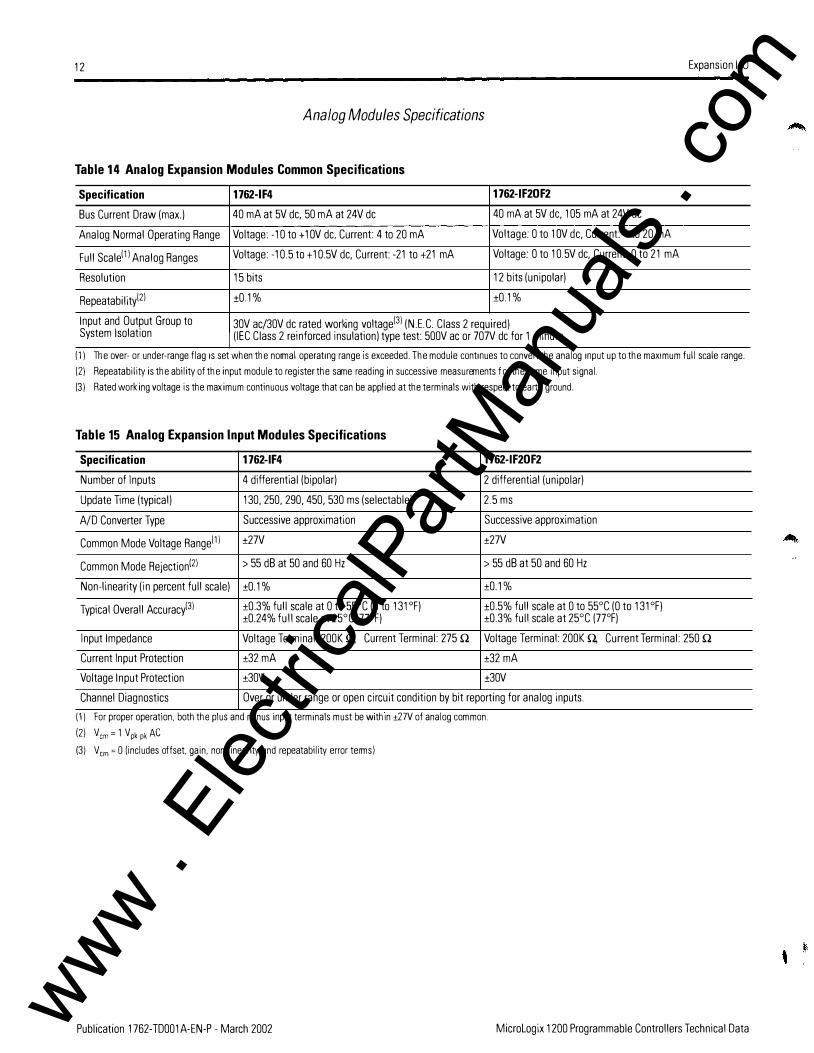
Table 14 Analog Expansion Modules Common Specifications
Specification 1762-IF4 1762-IF 20F 2 Bus Current Draw (max.) 40 mA at 5V de. 50 mA at 24V de 40 mA at 5V de, 105 mA at 24V de
Analog Normal Operating Range Voltage: -10 to+ 1 OV de. Current: 4 to 20 mA Voltage: 0 to 1 OV de, Current: 4 to 20 mA
Full Scalel1 I Analog Ranges Voltage: -10.5 to+ 1 0.5V de, Current: -21 to +21 mA Voltage: 0 to 10.5V de, Current 0 to 21 mA
Resolution 15 bits 12 bits (unipolar)
Repeatabilityl21 ±0.1% ±0.1%
Input and Output Group to 30V ac/30V de rated working voltagel31 (N.E.C. Class 2 required) System Isolation (IEC Class 2 reinforced insulation) type test: 500V ac or 707V de for 1 minute
(1) The over- or under-range flag 1s set when the normal operatmg range IS exceeded. The module contmues to convert the analog mput up to the max1 mu m full scale range.
( 2) Repeatability is the ability of the input module to register the same reading in successive measurements for the same input signal.
(3) Rated working voltage is the maximu m continuous voltage that can be applied at the ter minals with respect to earth ground.
Table 15 Analog Expansion Input Modules Specifications
Specif ication 1762-IF4 1762-IF 20F 2 Number of Inputs 4 differential (bipolar) 2 differential (unipolar)
Update Time (typical) 130. 250. 290, 450, 530 ms (selectable) 2.5 ms
A/D Converter Type Successive approximation Successive approximation
Common Mode Voltage Rangel11 ±27V ±27V
Common Mode Rejection121 > 55 dB at 50 and 60 Hz > 55 dB at 50 and 60 Hz
Non-linearity (in percent full scale) ±0.1% ±0.1%
Typical Overall Accuracyl31 ±0.3% full scale at 0 to 55°C (0 to 131°F) ±0.5% full scale at 0 to 55°C (0 to 131 °F) ±0.24% full scale at 25°C (7JCF) ±0.3% full scale at 25°C (7JCF)
Input Impedance Voltage Terminal: 200K Q, Current Terminal: 275 Q Voltage Terminal: 200K Q,
Current Input Protection ±32 mA ±32 mA
Voltage Input Protection ±30V ±30V
Channel Diagnostics Over or under range or open circuit condition by bit reporting for analog inputs.
(1) For proper operation. both the plus and m1nus mput ter minals must be Within ± 27V of analog com mon.
( 2) Vcm = 1 Vpkpk AC (3) Vcm = 0 (includes offset. gain. non-linearity and repeatability error terms)
Current Terminal: 250 Q
Publication 1762-TD001A-EN-P - March 2002 Micrologix 1200 Programmable Controllers Technical Data www . El
ectric
alPar
tMan
uals
. com

Expansion 1/0
Table 16 Analog Expansion Output Module Specifications
Specif ication Number of Outputs
Update Time (typical)
0/A Converter Type
Resistive Load on Current Output
Load Range on Voltage Output
Reactive Load, Current Output
Reactive Load, Voltage Output
Typical Overall Accuracyl1 l
Output Ripple, range 0 to 500 Hz (referred to output range)
Non-linearity (in percent full scale)
Open and Short-Circuit Protection
Output Protection . .
(1) Includes offset, gam, non-lmeanty and repeatability error terms.
MicroLogix 1200 Programmable Controllers Technical Data
13
1762-IF20F 2 2 single-ended (unipolar)
4.5 ms
Resistor string
0 to 500 Q(includes wire resistance)
> 1KQ
<0.1 mH
<11lf ± 1% full scale at 0 to 55°C (0 to 131 °F), ±0.5% full scale at 25°C (7JCF)
<±0.1%
<±0.5%
Continuous
±32 mA
Publication 1762-TD001 A-EN-P - March 2002 www . El
ectric
alPar
tMan
uals
. com
14 Communications
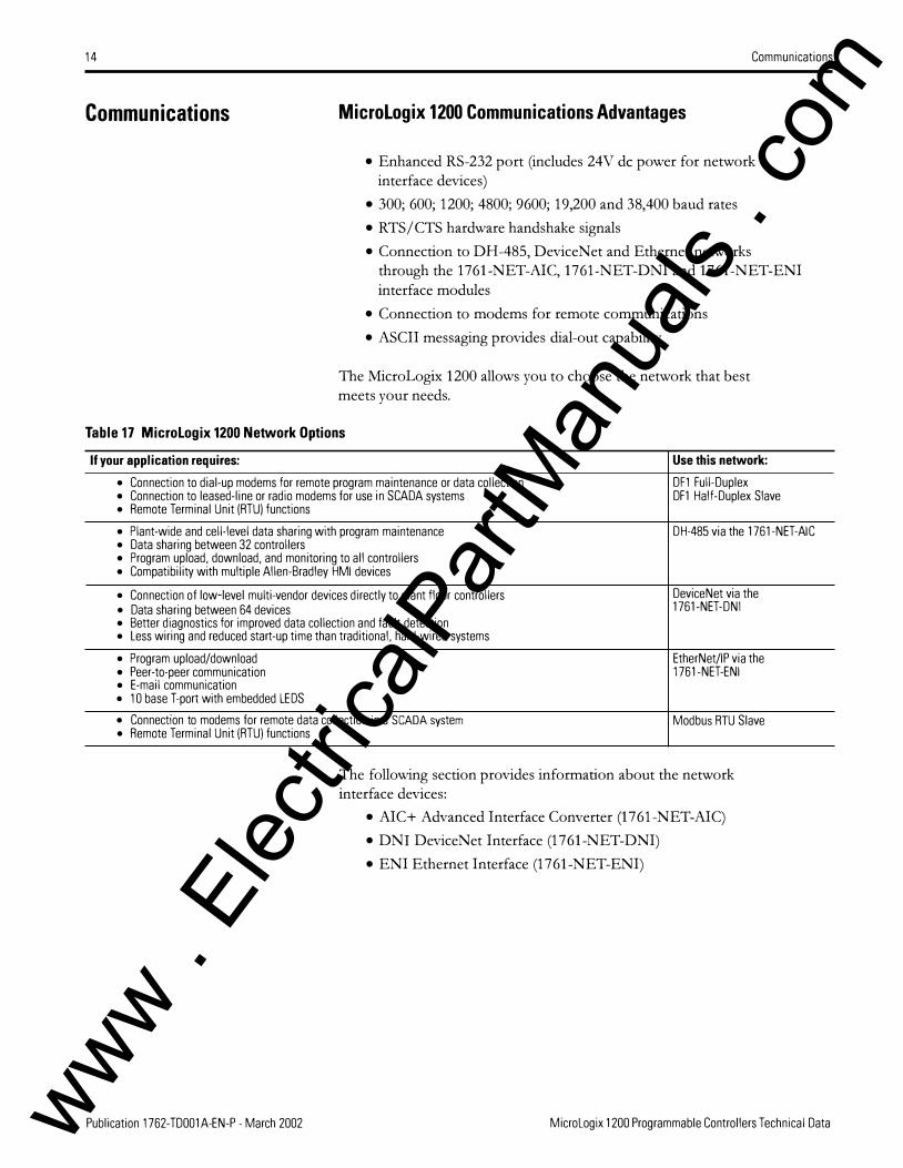
Communications Micrologix 1200 Communications Advantages
• Enhanced RS-232 port (includes 24V de power for network interface devices)
• 300; 600; 1200; 4800; 9600; 19,200 and 38,400 baud rates
• RTS/CTS hardware handshake signals
• Connection to DH-485, DeviceNet and Ethernet networks through the 1761-NET-AIC, 1761-NET-DNI and 1761-NET-ENI interface modules
• Connection to modems for remote communications
• ASCII messaging provides dial-out capability
The MicroLogix 1200 allows you to choose the network that best meets your needs.
Table 17 Micrologix 1200 Network Options
If your application requires: • Connection to dial-up modems for remote program maintenance or data collection • Connection to leased-line or radio modems for use in SCADA systems • Remote Terminal Unit (RTU) functions
• Plant-wide and cell-level data sharing with program maintenance • Data sharing between 32 controllers • Program upload, download, and monitoring to all controllers • Compatibility with multiple Allen-Bradley HMI devices
• Connection of low-level multi-vendor devices directly to plant floor controllers • Data sharing between 64 devices • Better diagnostics for improved data collection and fault detection • Less wiring and reduced start-up time than traditional, hard-wired systems
• Program upload/download • Peer-to-peer communication • E-mail communication • 1 0 base T-port with embedded LEOS
• Connection to modems for remote data collection in a SCADA system • Remote Terminal Unit (RTU) functions
Use this netw ork: DF1 Full-Duplex DF1 Half -Duplex Slave
DH-485 via the 1761-NET-AIC
DeviceNet via the 1761-NET-DNI
EtherNet/IP via the 1761-NET-ENI
Modbus RTU Slave
The following section provides information about the network interface devices:
• AIC+ Advanced Interface Converter (1761-NET-AIC)
• DNI DeviceNet Interface (1761-NET-DNI)
• ENI Ethernet Interface (1761-NET-ENI)
Publication 1762-TD001A-EN-P - March 2002 MicroLogix 1200 Programmable Controllers Technical Data www . El
ectric
alPar
tMan
uals
. com

Communications
Network Interface Devices
The network interface devices can be mounted on a panel or DIN rail. See Figure 24 on page 18 for device drawings.
AIC+ Advanced Interface Converter (1767-NET-AIC)
The AIC+ provides an interface to DH-485 networks from an RS-232 port. It can be used with alll\1icroLogix controllers, SLC 5/03 and higher, and a number of PanelView terminals. All devices
communicating on the network must be using DH485 protocol. Do
not use DH485 protocol to communicate with modems.
The AIC+ also provides isolation between all ports for a more stable network and protection for connected devices.
Table 18 DH-485 Network Specifications(1l
Specif ication 1761-NET-AIC Maximum Number of Nodes 32 per multidrop network
Maximum Length 1219m (4000 ft) per multidrop network
(1) See Table 21, Network Modules Specifications, for more 1761-NET-AIC spec1f1cat1ons.
DNI DeviceNet Interface (1767-NET-DNI)
DNI capabilities:
• Peer-to-peer messaging between Allen-Bradley controllers and other devices using the DF1 Full-Duplex protocol
• Programming and on-line monitoring over the DeviceNet network
• With a DNI connected to a modem, you can dial in to any other DNI-controller combination on DeviceNet
• Other DeviceN et products can send explicit (Get or Set) messages with the DNI at any time
• The controller can initiate an explicit message to a UCMM (Unconnected Message Manager) compatible device on DeviceNet
Table 19 DeviceNet Specifications11l
Specif ication 1761-NET-DNI Maximum Number of Nodes 64
Maximum Length 500m at 125K baud or 1OOm at 500K baud
DeviceNet Agency Certification ODVA conformance 2.0-A 12
(1) See Table 21, Network Modules Spec1f1cat1ons, for more 1761-NET-ONI spec1f1cat1ons.
15
MicroLogix 1200 Programmable Controllers Technical Data Publication 1762-TD001A-EN-P - March 2002 www . El
ectric
alPar
tMan
uals
. com

16 Communications
EN/ Ethernet Interface (1761-NET-EN/)
The ENI provides EtherNet/IP connectivity for all MicroLogix controllers and other DF1 Full-Duplex devices. The ENI allows you to easily connect a MicroLogix controller to a new or existing Ethernet network to update/ download programs, communicate between controllers, and generate e-mail messages via SMTP (simple mail transport protocol) .
Table 20 Ethernet Specifications(11
Specification 1761-NET-ENI Communication Rate 10 MHz
Connector 1 OBase-T (RJ45)
(1) See Table 21. Network Modules Specifications, for more 1761-NET-ENI specifications.
AIC+, ON/, and EN/ Specifications
Table 21 Network Modules Specifications
Specif ication 1761-NET-AIC 1761-NET-DNI 1761-NET-ENI 24V de Power Source 20.4 to 2B.BV de 11 to 25V de 20.4 to 26.4V de
Requirements!1 l 24V de Current Draw 120 mA 200 mA 100 mA
Inrush Current (max.) 200 mA 400 mA 200 mA
Internal Isolation 50DV de for 1 minute 500V de for one minute 710V de for one minute
Operating Temperature ooc to t60°C (+32°F to + 140°F) (0°C to t55°C (+32°F to+ 131 °F)
Storage Temperature -40°C to +85°C (-40°F to+ 185°F)
Humidity 5% to 95% non-condensing
Vibration operating: 10 to 500 Hz, 5.0g, 0.030 in. operating: 5 to 2000 Hz, 2.5g, 0.015 in. operating: 10 to 500 Hz, 5 Og, 0.030 in. peak-to-peak, 2 hour each axis peak-to-peak, 1 hour each axis peak-to-peak, 2 hour each axis
non-operating: 5 to 2000Hz, 5.0g, 0.030 in. peak-to-peak, 1 hour each axis
Shock operating: 30g, ±3 times each axis operating: 30g, ±3 times each axis operating: 30g, ±3 times each axis non-operating: 50g, ±3 times each axis non-operating: 50g, ±3 times each axis non-operating: 35g (DIN rail mount) 50g
(panel mount) ±3 times each axis
Agency Certification
c@us UL Listed Industrial Control Equipment UL Listed Industrial Control Equipment for use in Canada UL Listed Industrial Control Equipment for use in Class I, Division 2 Hazardous Locations Groups A, B, C, D
CE: Marked for all applicable directives
0 Marked for all applicable acts
N223
(1) When the dev1ce IS connected to a M1crolog1x controller, power IS prov1ded by the M1crolog1x controller s commun1cat1on port.
Publication 1762-TOOD1A-EN-P - March 2002 MicroLogix 1200 Programmable Controllers Technical Data www . El
ectric
alPar
tMan
uals
. com

Programming Instructions
Programming Instructions
Programming Software
The MicroLogix 1200 has the range of functionality necessary to address diverse applications. The controller uses the following types of instructions:
• Basic Instructions
• Comparison Instructions
• Data Instructions
• Communication Instruction, including ASCII
• Math Instructions
• Program Flow Control Instructions
• Application Specific Instructions
• High-Speed Counter Instruction
• High-Speed PTO (Pulse Train Output) and PWM (Pulse Width Modulated) Instructions
The RSLogix 500 ladder logic programming package helps you maximize performance, save project development time, and improve productivity. This product has been developed to operate on
Windows® operating systems. RSLogix 500 can be used for programming both the SLC 500 and MicroLogix controller families.
Table 22 RSLogix 500 Selection Chart
Catalog Number 9324-RL0300ENE
9324-RL01 OOENE
Description RSLogix 500 Standard Edition Programming Software for SLC 500 and Micrologix controller families. (CD-ROM)
RSLogix 500 Starter Edition Programming Software for Micrologix controller families. (CD-ROM)
17
9324-RL0700NXENE RSLogix 500 Professional Edition. CD-ROM also includes RSLogix Emulate 500, RSNetworx for DeviceNet and RSNetworx for Control Net.
Micrologix 1200 Programmable Controllers Technical Data Publication 1762-TD001A-EN-P - March 2002 www . El
ectric
alPar
tMan
uals
. com

18
Network and Programming Cables
Network and Programming Cables
Use the communication cables listed below with MicroLogix 1200 controllers. Cables come in several lengths and connector styles to provide connectivity between MicroLogix controllers and other devices.
MicroLogix 1200 controllers require Series C versions of al/1761
cables.
Table 23 Controller and PC Port Identification
Device Micrologix 1200 Controller Communications Port
Personal Computer Communications Port
Port 8-pin Mini DIN
9-Pin D Shell
Figure 24 Network Interface Devices Communication Port Identification
AIC+ DNI
DH-485
Table 25 Network Cable Selection Chart
8-pin Mini DIN to 8-pin Mini DIN
9-pin D Shell to 9-pin D Shell
9-pin D Shell to 9-pin D Shell
10m (32 ft) 2711-CBL-HM10
0 5m (1.5 ft) 1761-CBL-ACOO
3m (10 ft) 1747-CP3
Table 26 Programming Cable Selection Chart
ENI
8-Pin Mini DIN
6-pin Phoenix to RJ45 (DH-485)
6-pin Phoenix to RJ45 (DH-485)
MicroLog ix 1000, 1200, and 1500 MicroLog ix 1500 w ith 1764-LRP Processor Channel 0 (8-pin Mini DIN) Catalog Number Leng th 1761-CBL-PM02 2m (6.5 ft)
1761-CBL-HM02 2m (6.5 ft)
Channel1 (9-pin RS-23 2 ) Catalog Number
1747-CP3
n/a
Leng th 3m (10 ft)
NOTE: The AIC+ is recommended for isolation purposes when the controller and an operator interface device are not using the same power supply.
10m (32 ft) 2711-CBL-PM10
3m (10 ft) 1761-CBL-AS03
9m (30
Prog ramming Device
Personal Computer (9-pin D Shell)
Hand-Held Programmer (HHP)
Publication 1762-TD001A-EN-P - March 2002 Micrologix 1200 Programmable Controllers Technical Data www . El
ectric
alPar
tMan
uals
. com

Dimensions 1 9
Dimensions Dimensions are in millimeters (inches) .
Figure 27 Micrologix 1200 Controller Dimension Drawing
1762-L24AWA. 1762-L24BWA. 1 762-L24BXB 1762-L40AWA. 1 762-L40BWA. 1762-L40BXB
controller spacing= 50 mm (2 in.) on all sides for adequate ventilation
Table 28 Controller Dimensions
Dimension 1762-l24AWA )1162-l248WA j 1762-l248XB 1762-L40AWA j1162-L40BWA j1162-L408XB A 90 mm (3.5 in.) 90 mm (3.5 in.)
B 110 mm (4.33 in.) 1 60 mm (6.30 in.)
c 87 mm (3.43 in.) 87 mm (3.43 in.)
Figure 29 1762 Expansion 1/0 Dimensions
Dimension Expansion 1/0 Module A 90 mm (3.5 in.)
B 40 mm (1.57 in.)
c 87 mm (3.43 in )
Micrologix 1200 Programmable Controllers Technical Data Publication 1762-TD001A-EN-P- March 2002 www . El
ectric
alPar
tMan
uals
. com

20 Dimensions
Figure 30 Micrologix 1200 System Mounting Dimensions
r 100 90 Micrologix
(3.94) (3.54) 1200
U�� A= 95.86mm (3.774 in.)
1762-L24AWA. 1762-L24BWA, 1762-L24BXB
8 = 145.8 mm (5.739 in.) 1762-L40AWA, 1762-L40BWA, 1762-L40BXB
Figure 31 Network Interface Devices Dimensions
118 mm (4.64 in.)
52.07 mm (2.05 in.)
r········-···
! i !
I ! ! !
.,·. i
1.· I !
! I i �
107 mm (4.20 in.)
:· ··-··-··-··-�-··-·· .. ...
Allow 15 mm (0.6 in) for DIN rail latch movement during installation and removal.
Publication 1762-T0001 A-EN-P - March 2002
27.7 mm (1 09 in.)
NOTE: All dimensions are in mm (inches). Hole spacing tolerance: ±0.4 mm (0.016 in.).
64.8 mm (2.55 in.)
71.4 mm (2.81 in.) AIC+ only
Micrologix 1200 Programmable Controllers Technical Data www . El
ectric
alPar
tMan
uals
. com

System Expansion Calculations
System Expansion Calculations
A download is also available for system validation. On the Internet, go to http://www;ab.com/micrologix and navigate to MicroLogix 1200.
To have a valid system, both current and power requirements must be satisfied. Use the following worksheets to make your calculations.
Table 32 MicroLogix 1200 Power Supply Loading- Calculate System Current
Catalog Number Bus Current Draw Specification Calculated Current for System at 5 V de (rnA) at 24V de (rnA) at 5 V de (rnA) at 24V de (rnA)
1761-NET-AICI11 0 120111
1761-NET-ENII11 0 100(1)
2707 -MVH232 or 2707 -MVP232111 0 sol11 Catalog Number n = Number of Modules
(&maximum) A 8 nxA nxB
1762-IAS 50 0
1762-0AB 115 0
1762-0BB 115 0
1762-0816 175 0
1762-0WB 80 90
1762-0W16 120 140
1762-108 50 0
1762-1016 60 0
1762-IF4 40 50
1762-IF20F2 40 105
TOTAL MODULES: TOTAL CALCULATED CURRENT: (C) For 1762-L248WA and 1762-L40BWA only, add sum of any User 24V de Sensor Current
21
(D) (E)j
(1) Current for the AICt may be supplied by controller co mmun1cat1ons port or from an external 24V de source. No current IS consumed from the controller when an external source is used. The current for a 2707-MVH232 or 2707- MVP232 Micro View Operator Interface is supplied from the controller communication port, if directly connected.
Table 33 MicroLogix 1200 Maximum Load Current
Catalog Number Load Current 5 V de 24V de User 24V de Sensor Current
1762-L24AWA Calculated Value (C) (D) n/a 1762-L24BXB MAXIMUM LIMIT 400mA 350mA 1762-L24BWA Calculated Value (C) (D) (E)
MAXIMUM LIMIT 400mA 3 50mA 250mA 1762-L40AWA Calculated Value (C) (D) n/a 1762-L40BXB MAXIMUM LIMIT 600mA 500mA 1762-L40BWA Calculated Value (C) (D) (E)
MAXIMUM LIMIT 600mA 500mA 400mA
Micrologix 1200 Programmable Controllers Technical Data Publication 1762-TD001 A-EN-P- March 2002 www . El
ectric
alPar
tMan
uals
. com

22 System Expansion Calculations
To verify the Base Unit power supply loading:
1. Use Table 32 to select the components for your system. Do not exceed the :MAXIMUM LIMIT for the number of I/ 0 modules.
2. Fill in the current amounts and add up the TOTAL CALCULATED CURRENT.
3. Using Table 33, verify that (C), (D), and (E) do not exceed the MAXIMUM LIMITS. If the MAXIMUM LIMIT is exceeded, you will need to adjust your selections.
4. Use Table 34 to verify that the system is within the power loading limits of the controller.
To use Table 34, fill in the (C), (D), and (E) values where indicated. Then calculate Watts and add up the Total Watts. Verify that Total Watts does not exceed the MAXIMUM POWER LIMIT. If the :MAXIMUM POWER LIMIT is exceeded, you will need to adjust your selections.
Table 34 Micrologix 1200 Maximum Load Power
Catalog 5V Pow er Consumption 24V Pow er Consumption Calculated Watts MAXIMUM Number Calculated Watts Calculated Watts (sum of 5V and 24V) POWER LIMIT
1762-L24AWA (C) x5V =W ( D) x24V =W w 1 0.4W 1762-L24BXB (C) x5V =W ( D) x24V =W w 1 0.4W 1762-L24BWA (C) x5V =W ( D)+(E) x24V =W w 12W 1762-L40AWA (C) x5V =W ( D) x24V =W w 15W 1762-L40BXB (C) x5V =W ( D) x24V =W w 15W 1762-L40BWA (C) x5V =W ( D)+(E) x24V =W w 16W
Publication 1762-TD001A-EN-P- March 2002 Micrologix 1200 Programmable Controllers Technical Data www . El
ectric
alPar
tMan
uals
. com
For More Information
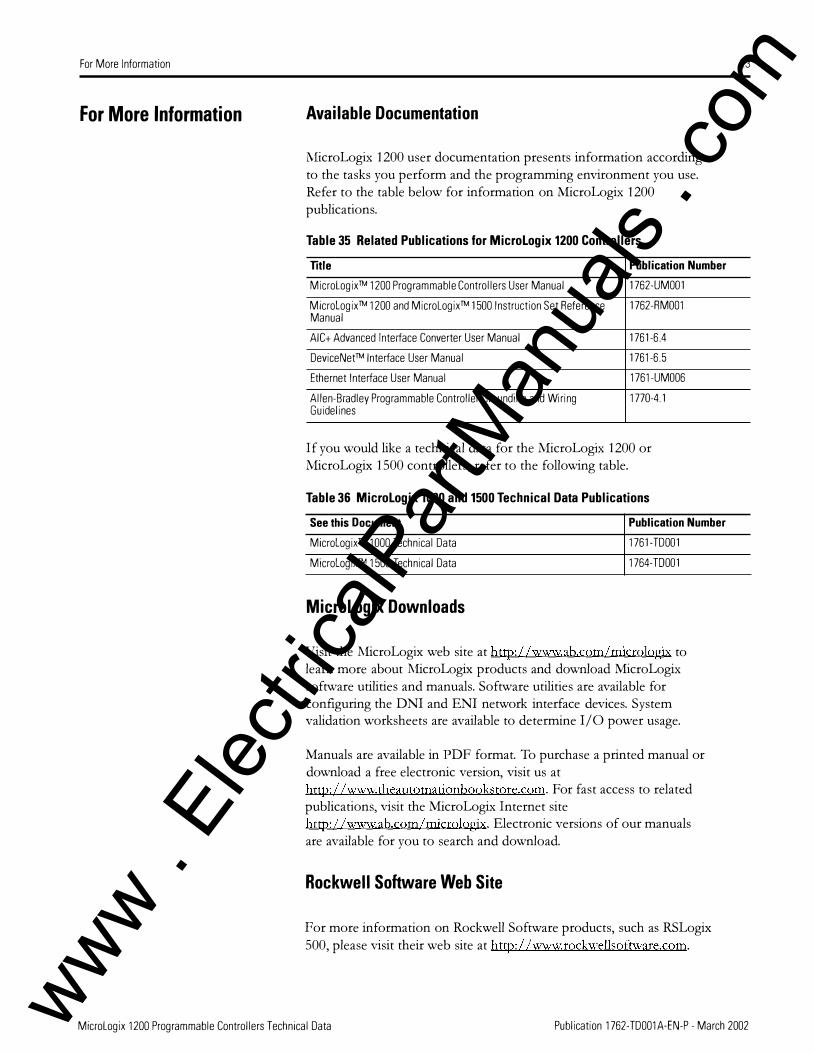
For More Information Available Documentation
l\1icroLogix 1200 user documentation presents information according to the tasks you perform and the programming environment you use. Refer to the table below for information on l\1icroLogix 1200 publications.
Table 35 Related Publications for Micrologix 1200 Controllers
Title Publication Number Micrologix™ 1200 Programmable Controllers User Manual 1762-UM001
Micrologix™ 1200 and Micrologix™ 1500 Instruction Set Reference 1762-RM001 Manual
AIC+ Advanced Interface Converter User Manual 1761-6.4
Device Net™ Interface User Manual 1761-6.5
Ethernet Interface User Manual 1761-UM006
Allen-Bradley Programmable Controller Grounding and Wiring 1770-4.1 Guidelines
If you would like a technical data for the l\1icroLogix 1200 or l\1icroLogix 1500 controllers, refer to the following table.
Table 36 Micrologix 1000 and 1500 Technical Data Publications
See this Document Publication Number Micrologix™ 1000 Technical Data 1761-TD001
Micrologix™ 1500 Technical Data 1764-T0001
Micrologix Downloads
Visit the l\1icroLogix web site at http://www.ab.com/micrologix to learn more about l\1icroLogix products and download MicroLogix software utilities and manuals. Software utilities are available for configuring the DNI and ENI network interface devices. System validation worksheets are available to determine I/0 power usage.
Manuals are available in PDF format. To purchase a printed manual or download a free electronic version, visit us at http://www.theautomationbookstore.com. For fast access to related publications, visit the MicroLogix Internet site http://www.ab.com/micrologix. Electronic versions of our manuals are available for you to search and download.
Rockwell Software Web Site
For more information on Rockwell Software products, such as RSLogix 500, please visit their web site at http://www;rockwellsoftware.com.
23
Micrologix 1200 Programmable Controllers Technical Data Publication 1762-TD001A-EN-P - March 2002 www . El
ectric
alPar
tMan
uals
. com

Allen-Bradley, SLC, Micrologix, RSLogix, RSNetworx, ControiNet, MicroView, and PaneiView are trademarks of Rockwell Auto mation. DeviceNet is a trademark of Open DeviceNet Vendors Association IODVA).
www.rockwellautomation.com
Corporate Headquarters Rockwell Automation, 777 East Wisconsin Avenue, Suite 1400, Milwaukee, WI, 53202-5302 USA, Tel: (1) 414.212.5200, Fax: (1) 414.212.5201
Headquarters for Allen-Bradley Products, Rockwell Software Products and Global Manufacturing Solutions Americas: Rockwell Automation, 1201 South Second Street. Milwaukee, WI 53204-2496 USA, Tel: (1) 414.382.2000, Fax: (1) 414.382.4444 Europe: Rockwell Automation SA/NV, Vorstlaan/Boulevard du Souverain 36-BP 3A/B, 1170 Brussels, Belgium, Tel: (32) 2 663 0600, Fax: (32) 2 663 0640 Asia Pacific: Rockwell Automation, 27 /F Citicorp Centre, 18 Whitfield Road, Causeway Bay, Hong Kong, Tel: (852) 2887 4788, Fax: (852) 2508 1846
Headquarters for Dodge and Reliance Electric Products Americas: Rockwell Automation, 6040 Ponders Court, Greenville, SC 29615-4617 USA, Tel: (1) 864.297.4800, Fax: (1) 864.281.2433 Europe: Rockwell Automation, Bruhlstra!Se 22, 0-74834 Elztai-Oallau, Germany, Tel: (49) 6261 9410, Fax: (49) 6261 17741 Asia Pacific: Rockwell Automation, 55 Newton Road, #11-01/02 Revenue House, Singapore 307987, Tel: (65) 351 6723, Fax: (65) 355 1733
Publication 1762-TD001A-EN-P - March 2002 Supersedes Publication 1762-S0001 A-US-P- November 1999 Copyright© 2002 Rockwell Automation All rights reserved. Printed 1n the US A www .
Elec
tricalP
artM
anua
ls . c
om