Embed Size (px)
Citation preview
www.engineersfox.com
CAD/CAM
www.engineersfox.com
INTRODUCTION
Computer-aided design (CAD) is the use of computer systems to assist in the creation, modification, analysis, or optimization of a design.
Computer-aided manufacturing (CAM) is the use of computer systems to plan, manage, and control the operations of a manufacturing plant through direct or indirect computer interface with plant’s resources.
www.engineersfox.com
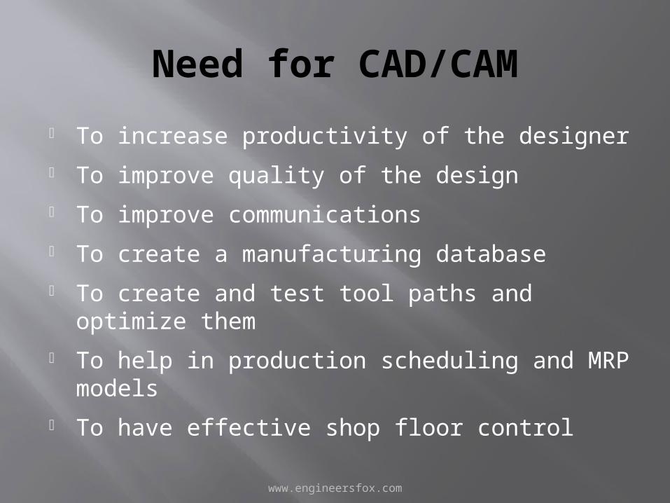
Need for CAD/CAM
• To increase productivity of the designer• To improve quality of the design• To improve communications• To create a manufacturing database• To create and test tool paths and optimize
them • To help in production scheduling and MRP
models• To have effective shop floor control
www.engineersfox.com
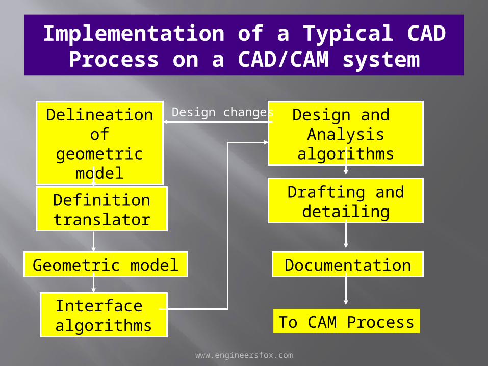
Implementation of a Typical CAD Process on a CAD/CAM system
Delineation of geometric
model
Definition translator
Geometric model
Design and Analysis
algorithms
Drafting anddetailing
Documentation
To CAM ProcessInterface algorithms
Design changes
www.engineersfox.com
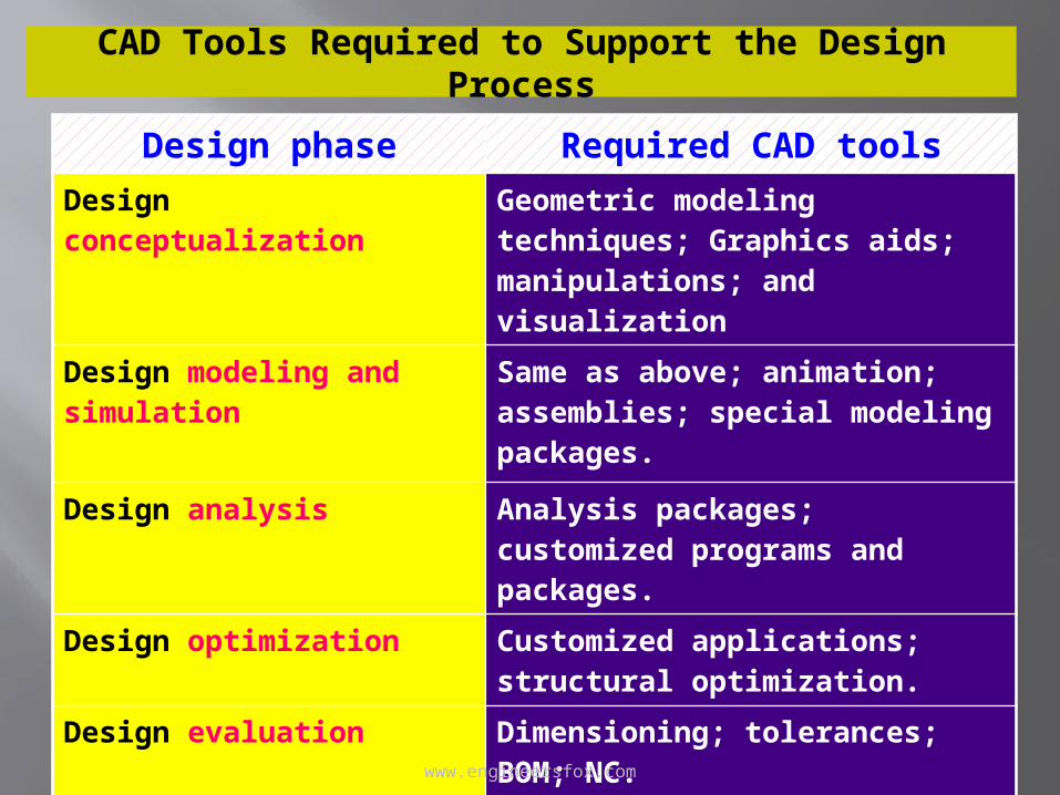
CAD Tools Required to Support the Design Process
Design phase Required CAD toolsDesign conceptualization Geometric modeling techniques;
Graphics aids; manipulations; and visualization
Design modeling and simulation Same as above; animation; assemblies; special modeling packages.
Design analysis Analysis packages; customized programs and packages.
Design optimization Customized applications; structural optimization.
Design evaluation Dimensioning; tolerances; BOM; NC.
Design communication and documentation
Drafting and detailing…
www.engineersfox.com
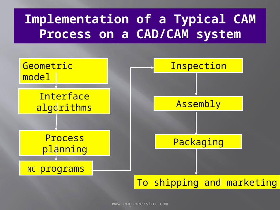
Implementation of a Typical CAM Process on a CAD/CAM system
Geometric model
Interface
algorithms
Process planning
Inspection
Assembly
Packaging
To shipping and marketing
NC programs
www.engineersfox.com
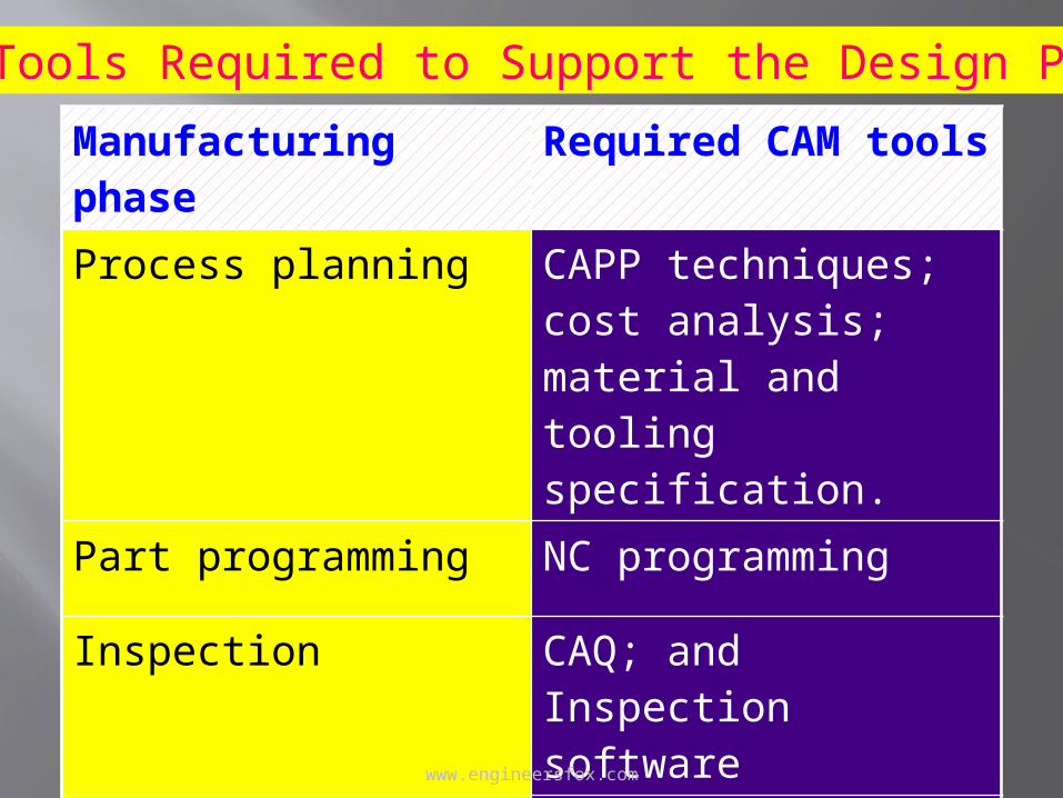
Manufacturing phase Required CAM tools
Process planning CAPP techniques; cost analysis; material and tooling specification.
Part programming NC programming
Inspection CAQ; and Inspection software
Assembly Robotics simulation and programming
CAM Tools Required to Support the Design Process
www.engineersfox.com
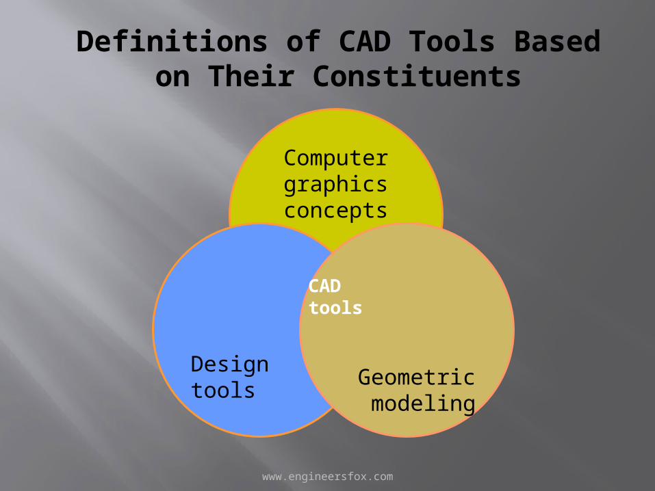
Definitions of CAD Tools Based on Their Constituents
Computer graphics concepts
Design toolsGeometric modeling
CADtools
www.engineersfox.com
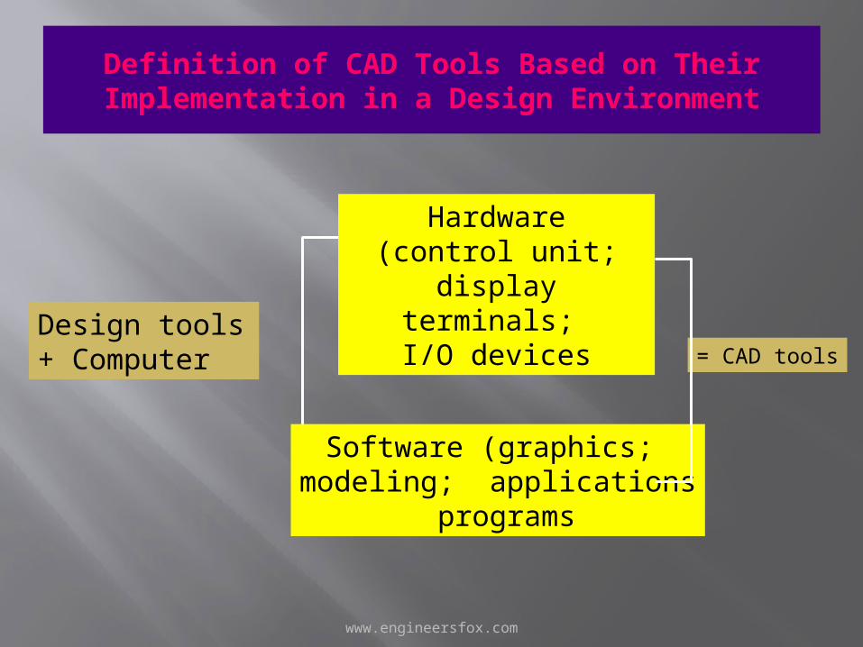
Definition of CAD Tools Based on Their Implementation in a Design Environment
Design tools + Computer
Hardware(control unit; display
terminals; I/O devices
Software (graphics; modeling; applications
programs
= CAD tools
www.engineersfox.com
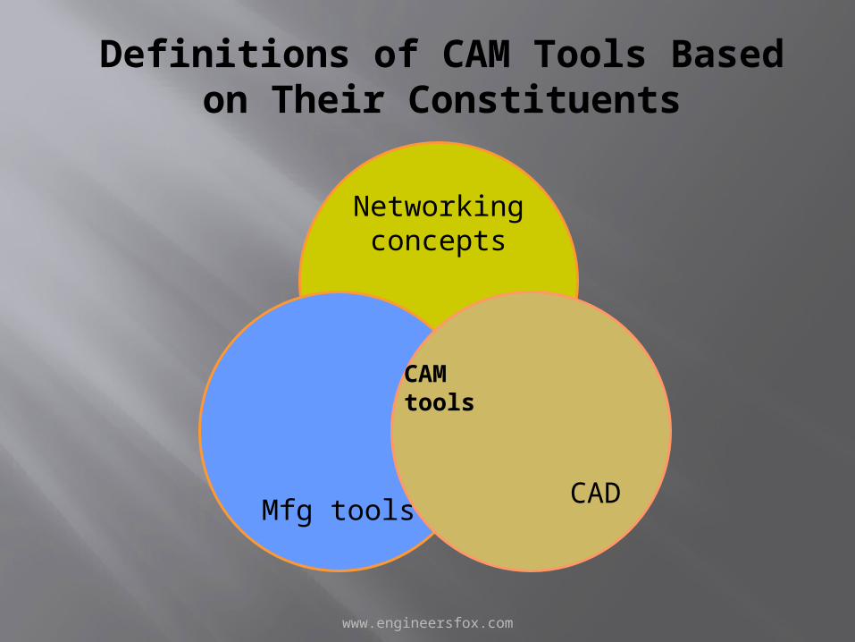
Definitions of CAM Tools Based on Their Constituents
Networking concepts
Mfg toolsCAD
CAMtools
www.engineersfox.com
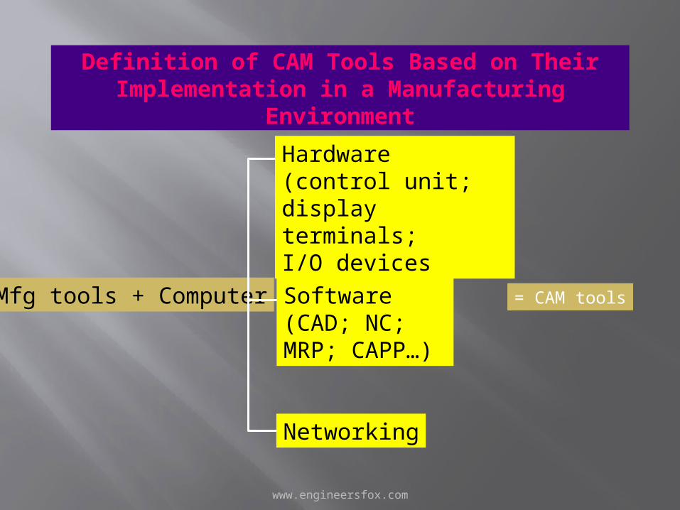
Definition of CAM Tools Based on Their Implementation in a Manufacturing
Environment
Mfg tools + Computer
Hardware(control unit; display terminals; I/O devices
Software (CAD; NC; MRP; CAPP…)
= CAM tools
Networking
www.engineersfox.com
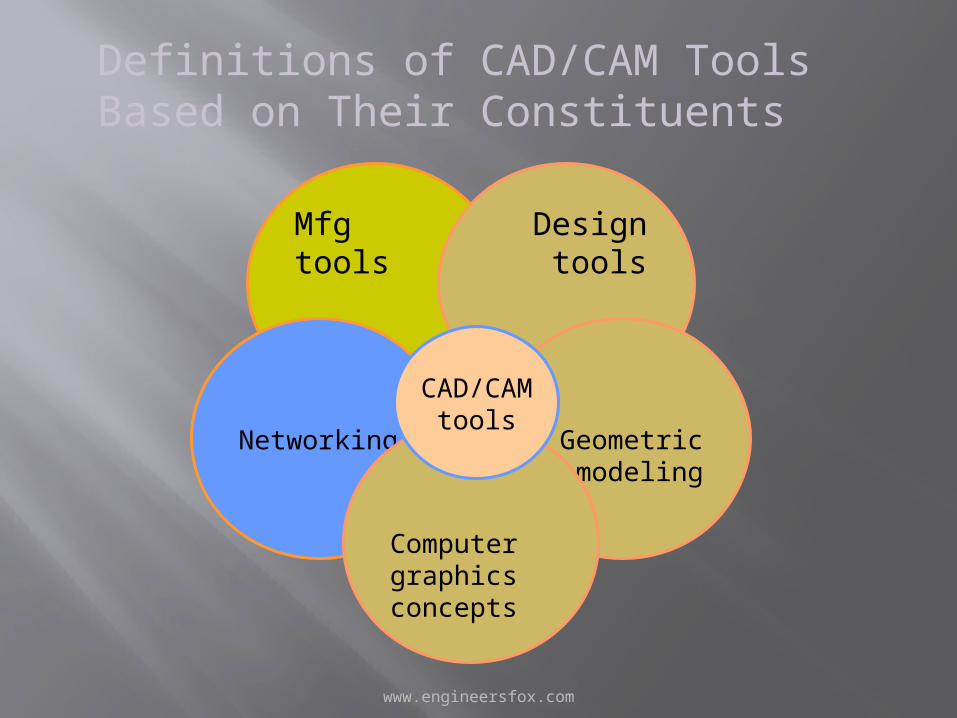
Definitions of CAD/CAM Tools Based on Their Constituents
Mfg tools
Networking
Design tools
Geometric modeling
Computer graphics concepts
CAD/CAMtools
www.engineersfox.com
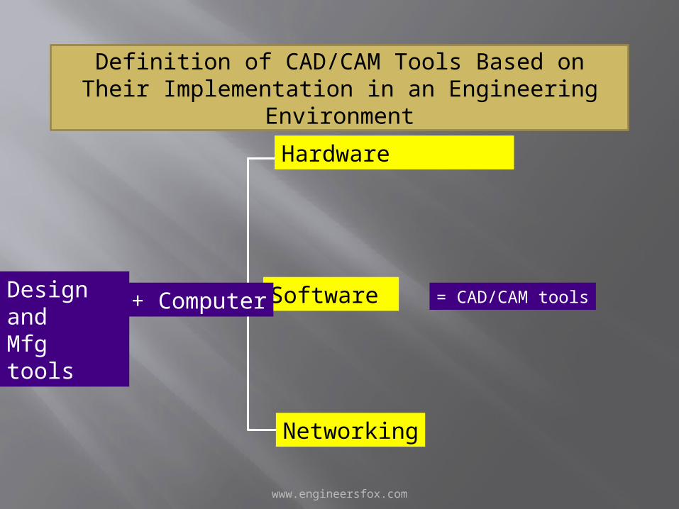
Definition of CAD/CAM Tools Based on Their Implementation in an Engineering Environment
Design andMfg tools
Hardware
Software = CAD/CAM tools
Networking
+ Computer
www.engineersfox.com
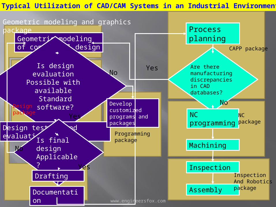
Geometric modeling of conceptual design
Is design evaluation Possible with
available Standard software?
Design testing And evaluation
Is final designApplicable?
Drafting
Documentation
Process planning
Are there manufacturing discrepancies in CAD databases?
NC programming
Machining
Inspection
Assembly
Develop customized programs and packages
No
Yes
Yes
Yes
Geometric modeling and graphics package
Design package
Programmingpackage
No
No
CAPP package
NCpackage
InspectionAnd Roboticspackage
Typical Utilization of CAD/CAM Systems in an Industrial Environment
www.engineersfox.com
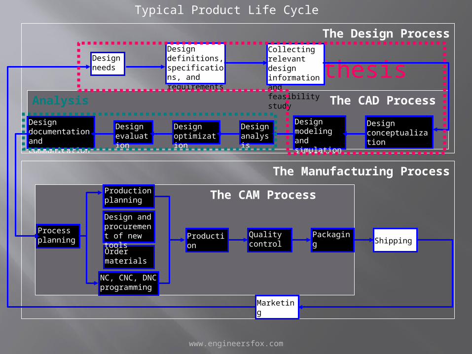
The Manufacturing Process
The Design Process
Synthesis Analysis The CAD Process
The CAM Process
Design needs
Design definitions, specifications, and requirements
Collecting relevant design information and feasibility study
Design conceptualization
Design modeling and simulation
Design analysis
Design optimization
Design evaluation
Design documentation and communication
Process planning
Order materials
Design and procurement of new tools
Production planning
NC, CNC, DNC programming
Production
Quality control
Packaging
Marketing
Shipping
Typical Product Life Cycle

www.engineersfox.com
System hardware 4.3.2 OVERVIEW OF PENTIUM PCThe hardware of a Pentium computer consists of the following:i. Mother boardii. Hard disc/floppy disc controller cardiii. Graphics adapter cardiv. Input/Output cardv. Switch mode power supplyvi. Floppy disc drivevii. Hard disc driveviii. CD-ROM drive
www.engineersfox.com
GRAPHICS SYSTEMGraphics system consists of four subsystems:a. Geometry engine subsystemb. Scan conversion subsystemc. Raster subsystemd. Display subsystem
www.engineersfox.com
RASTER SUBSYSTEMThe raster subsystem will have usually 24 bit planes. This will provide eight bit planes foreach primary color (RGB) so that (28) shades of a single color can thus obtain.Since the different colors are obtained by the three primary colors a total of (28)3colorsare available on the screen.In a typical raster engine five 256K X 4D RAM provide 4 bits of Z-depth. The rasterinformation is stored in the frame buffer. Twenty 64 K X 4 video RAM provide 4 bits foreach pixel of 1280 X 1024 resolution. Entry level systems will have 12 bit planes and highend systems will have 32 bit planes for the frame buffer. These provide the color anddepth for the images.
www.engineersfox.com
INTERACTIVE DISPLAY DEVICES
The display devices be can classified intotwo groups:i. Display devices based on CRT principleii. Flat screensMost interactive CAD systems use CRT based graphic monitors. CRT is a glass enclosedtube in which a finely focused electron beam is deflected to a phosphor coated screen. Thescreen then glows to produce a visible trace when excited by impinging electrons
www.engineersfox.com
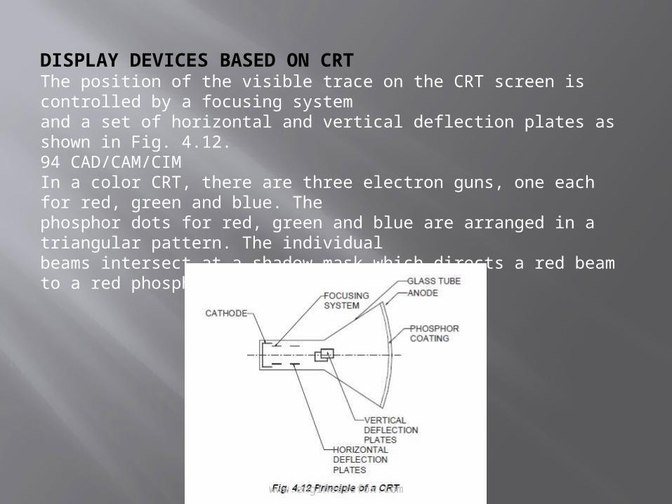
DISPLAY DEVICES BASED ON CRTThe position of the visible trace on the CRT screen is controlled by a focusing systemand a set of horizontal and vertical deflection plates as shown in Fig. 4.12.94 CAD/CAM/CIMIn a color CRT, there are three electron guns, one each for red, green and blue. Thephosphor dots for red, green and blue are arranged in a triangular pattern. The individualbeams intersect at a shadow mask which directs a red beam to a red phosphor dot and so on.
www.engineersfox.com
RASTER SCAN TECHNIQUE
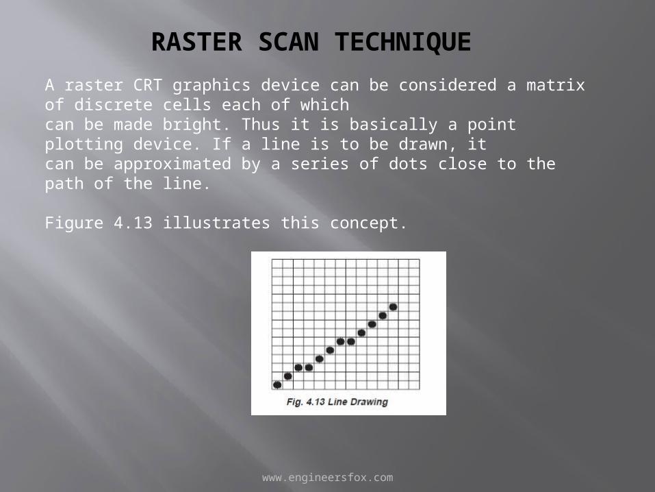
A raster CRT graphics device can be considered a matrix of discrete cells each of whichcan be made bright. Thus it is basically a point plotting device. If a line is to be drawn, itcan be approximated by a series of dots close to the path of the line.
Figure 4.13 illustrates this concept.
www.engineersfox.com
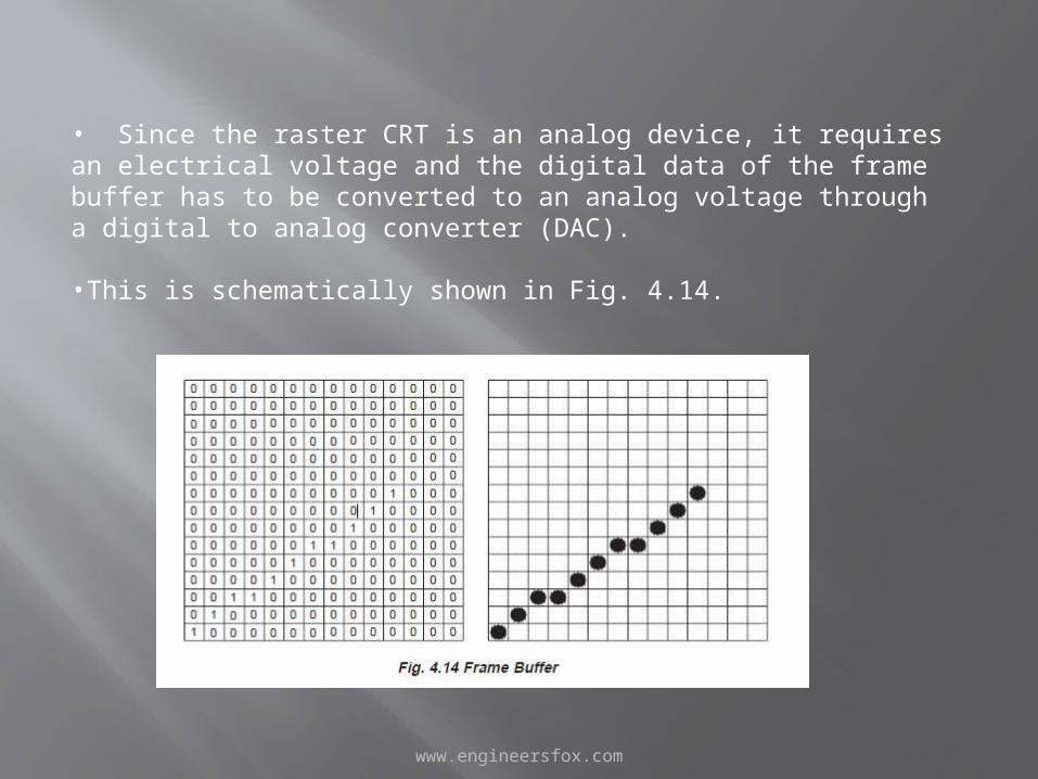
• Since the raster CRT is an analog device, it requires an electrical voltage and the digital data of the frame buffer has to be converted to an analog voltage through a digital to analog converter (DAC).
•This is schematically shown in Fig. 4.14.
www.engineersfox.com
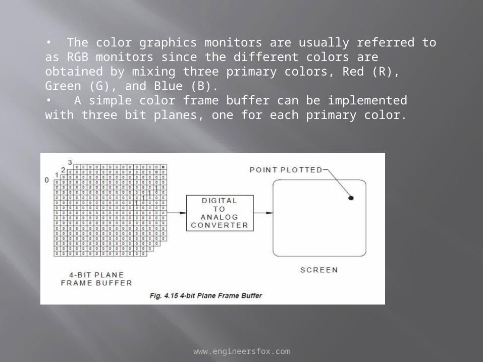
• The color graphics monitors are usually referred to as RGB monitors since the different colors are obtained by mixing three primary colors, Red (R), Green (G), and Blue (B). • A simple color frame buffer can be implemented with three bit planes, one for each primary color.
www.engineersfox.com
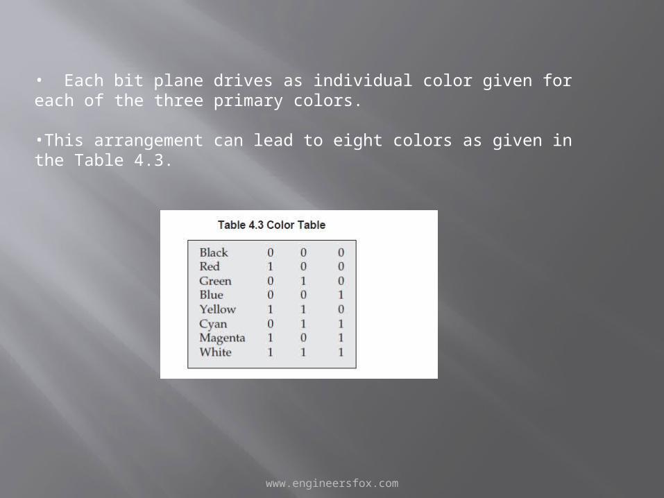
• Each bit plane drives as individual color given for each of the three primary colors.
•This arrangement can lead to eight colors as given in the Table 4.3.
www.engineersfox.com
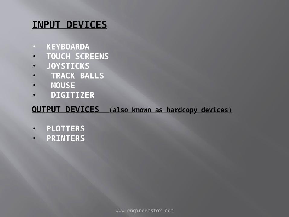
INPUT DEVICES
• KEYBOARDA• TOUCH SCREENS• JOYSTICKS• TRACK BALLS• MOUSE• DIGITIZER
OUTPUT DEVICES (also known as hardcopy devices)
• PLOTTERS• PRINTERS
www.engineersfox.com
Here are some different storage devices: Pen DriveCDDVDBlu-Ray disk Hard diskFloppy diskUSB DevicesMemory CardMultimedia CardRAMROMTape DriveCloud storageFlash memory
www.engineersfox.com
TRANSFORMATION IN GRAPHICS
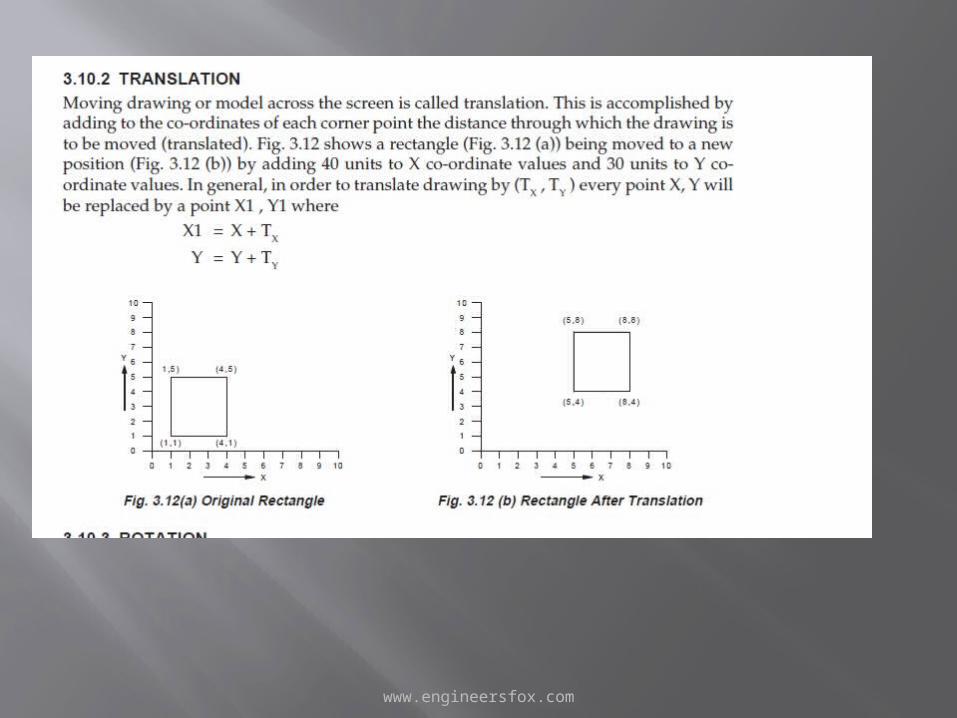
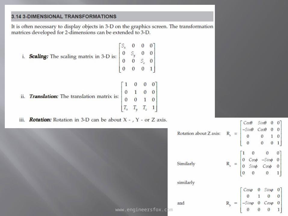
Geometric transformations provide a means by which an image can be enlarged in size, or reduced, rotated, or moved.
These changes are brought about by changing the co-ordinates of the picture to a new set of values depending upon the requirements.
www.engineersfox.com
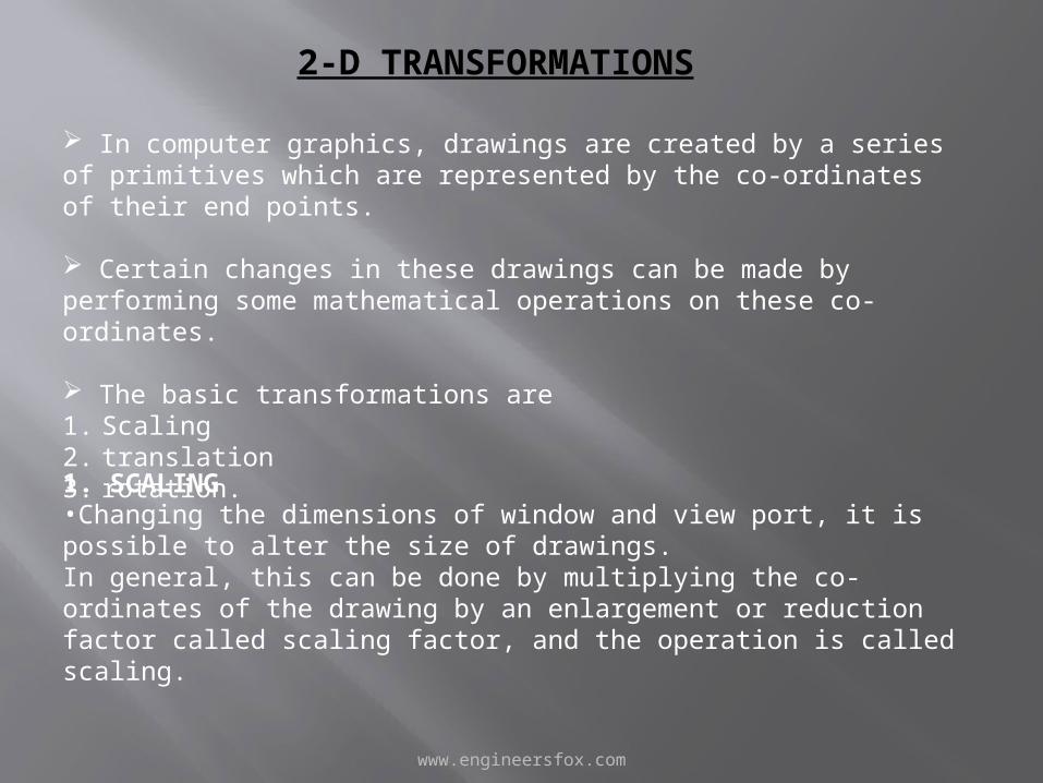
2-D TRANSFORMATIONS
In computer graphics, drawings are created by a series of primitives which are represented by the co-ordinates of their end points.
Certain changes in these drawings can be made by performing some mathematical operations on these co-ordinates.
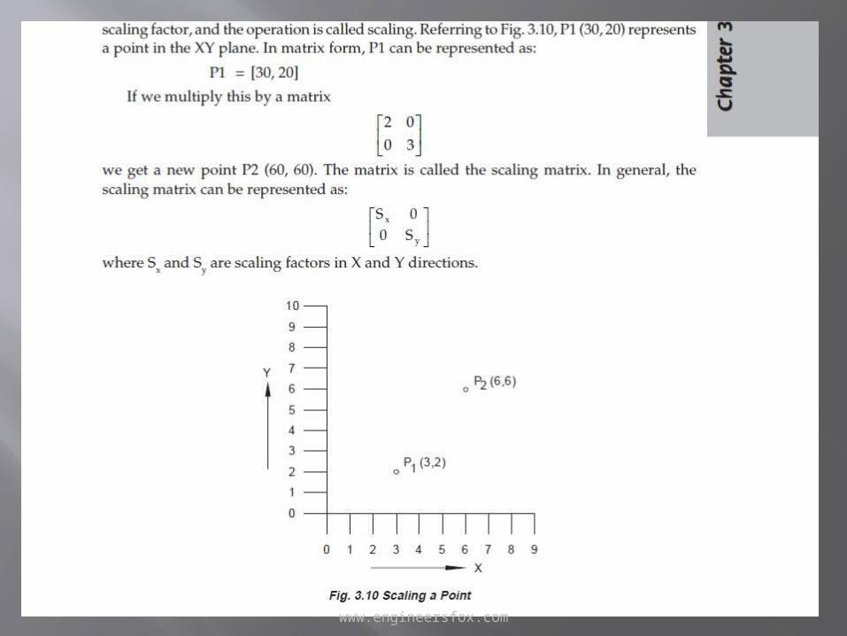
The basic transformations are 1. Scaling2. translation 3. rotation.1. SCALING•Changing the dimensions of window and view port, it is possible to alter the size of drawings. In general, this can be done by multiplying the co-ordinates of the drawing by an enlargement or reduction factor called scaling factor, and the operation is called scaling.
www.engineersfox.com
www.engineersfox.com

www.engineersfox.com
www.engineersfox.com

www.engineersfox.com