Embed Size (px)
Citation preview
HAL Id: jpa-00225877https://hal.archives-ouvertes.fr/jpa-00225877
Submitted on 1 Jan 1986
HAL is a multi-disciplinary open accessarchive for the deposit and dissemination of sci-entific research documents, whether they are pub-lished or not. The documents may come fromteaching and research institutions in France orabroad, or from public or private research centers.
L’archive ouverte pluridisciplinaire HAL, estdestinée au dépôt et à la diffusion de documentsscientifiques de niveau recherche, publiés ou non,émanant des établissements d’enseignement et derecherche français ou étrangers, des laboratoirespublics ou privés.
X-UV INTERFERENTIAL MIRRORS AND NEWPOSSIBILITIES FOR PLASMA RADIATION
STUDIESP. Dhez
To cite this version:P. Dhez. X-UV INTERFERENTIAL MIRRORS AND NEW POSSIBILITIES FOR PLASMARADIATION STUDIES. Journal de Physique Colloques, 1986, 47 (C6), pp.C6-267-C6-275.<10.1051/jphyscol:1986634>. <jpa-00225877>
JOURNAL DE PHYSIQUE, Colloque C6, supplement au no 10, Tome 47, octobre 1986
X-UV INTERFERENTIAL MIRRORS AND NEW POSSIBILITIES FOR PLASMA RADIATION STUDIES
P. DHEZ
Laboratoire de Spectroscopie Atomique et Ionique and LURE, Universite Paris XI, F-91405 Orsay Cedex, France
RESUME
La rea l i sa t ion de rniroirs in ter fbrent ie ls adapt& au domaine X-UV e s t une poss ib i l i t l apparue seulement depuis une dizaine d'annees. Dans une premiPre pa r t i e nous rappelons l e s ca rac t l r i s t i ques principales d e t e l s miroirs. Par comparaison avec l e s opt iques s o u s incidence r a san te s e u l e s disponibles &squJ& maintenanti nous indiquons ensu i t e l e s nouvelles >voies ouve r t e s par leur u t i l i sa t ion . Enfin nous dannons quelques exemples de diagnoctic de plasma t i r a n t par t ie de c e s nouvelles possibil i t8s.
ABSTRACT
For about t e n yea r s new multilayered X-UV mirrors have been in progress and a r e now overcoming some of t he main d i f icul t ies well Rnown with t h e grazing incidence opt ics used up t o now. The main character is t ics of such mirrors a r e f i r s t recalled. Next some of t he new poss ib i l i t ies in X-UV spectroscopy and imaging a r e given. Finally we briefly describe some examples of new s e t ups using such X-UV inter ference mirrors fo r plasma diagnostic.
INTRODUCTION.
Several papers a t t h i s f i r s t colloquium about "X-Ray Laser" demonstrate clearly t h e importance of plasma diagnost ics t o progress in t he understanding of t h e mecanisms leading t o t he population inversion and how t h e use of t he X-UV range i s well su i ted t o s tudy plasma temperature, dens i ty and character is t ic l i ne s of highly ionized atoms. Indeed, t he progress in such diagnostics using spectroscopy o r imaging opt ics a r e very dependant t o t he poss ib i l i t ies t o build t he correspoding X-UV optical s y s t e m s t o achieve them.
Until now, most of t h e s e t ups have been res t r ic ted t o grazing incidence and c r i s t a l opt ics (L). This is due t o t he X-U\/ optical cons tant values. Over a l l t he X-UV range; t hese one forbid a t t he same time t h e c lass ica l normal incidence mirrars witb s ingle in ter face , which need very absorbing material? and a l s o the ref rac t ive lenses , because ref rac t ive index i s t o o close t o t he vaccuum one. The qui te recent development of multilayered mirrors (2) and Fresnel zone p la te (3) had considerably enhanced t h e poss ib i l i t ies t o conceive X-UV optics b e t t e r adapted t o X-UV diagnostics. Based on diffraction properties, such in ter ferent ia l opt ics a r e no t similar t o t h e c lass ica l s ingle in ter face mirrors and ref rac t ive l e n s e s well Known in t h e visible range. To ge t such X-UV diffracting optics, specia l microfabrication technologies have been recently developed. The p re sen t s t a t e of a r t in t h i s new field permi ts t o overcome seve ra l l imi ta t ions which up t o now had slowed down the use of t he X-UV range.
In t h i s paper I will t ry f i r s t t o recall t h e basic proper t ies of t he X-UV in t e r f e ren t i a l mirrors. Next I will indicate new poss ib i l i t ies offered by such mirrors t o design new X-UV optics. Finally I will give some examples of new plasma diagnostics using these interference mirrars.
Article published online by EDP Sciences and available at http://dx.doi.org/10.1051/jphyscol:1986634
C6-268 JOURNAL DE PHYSIQUE
BASIC PROPERTIES OF THE INTERFERENTIAL X-UV MIRRORS
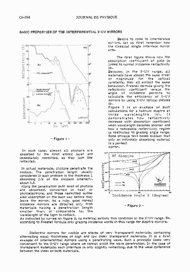
Before to come t o interference mirrors, l e t us f i r s t remember how the classical single interface mirror acts.
The f i r s t figure shows how the
.Pi absorpt ion coeff icient of gcld i s
u l o - Au linked to normal incidence reflectivit:, U a, (4). d 5- W ---Rl..,"",vcd*' Because, in the X-UV range, a l l a, materials have almost the same order
2- of magnitude f o r t h e opt ical constants, they al l exhibit the same behaviour. Fresnel formula giving the refectivity coefficient versus the angle af incidence permits t o calculate t h e efficiency of X-UV
L; mirrors by using X-UV optical indices (5). Figure 2 is an example of such calculations for a hafnium dioptre a t t h r e e w a v e l e n g t h s (6) . I t d e m o n s t r a t e s how r e f l e c t i v i t y
oh&& & "$a 2b0 & ' I ~ O decrease with absorption coefficient hv !eT7) when wavelength becomes shorter and
how a noticeable reflectivity regime is restricted to grazing angle range. Some physics text books explain that
- Figure 1 - only an infinitely absorbing material i s a perfect mirrur.
In such case, a lmost a l l photons a r e absorbed by the f i r s t atomic layer and immediately reemittedt s o they look like reflected.
In actual materials, phatons penetrate the medium. The penetration length usually considered in such problem is the thicUness L - absorbing i / e of the incident intensity, about O,3. Along the penetration path most of photons -
a r e absorbed, converted in h e a t or 10-0
photoelectronst and those reemitted suffer o 45 90
also absorption on the back way before they Incidence Angle 0 (degree)
leave the mirror. As a rul?, good normal incidence mirrors are obtained only from - Figure 2 - mater ia l s having a pene t ra t ion length smaller than , o r comparable t o , t h e wavelength of the light t o reflect. As indicated by curves on figure 3, no material sat isfy this condition in the X-UV range. Sot according t o Fresnel formula only grazing incidence worKs in th i s range for dioptre mirrurs.
Dielectric mirrors for visible are stacUs of very transparent materials, containing alternating equal thichkness of high and low index transparent materials. I t is a f i r s t example of interferential mirrors using a penetrating wave. Such a principle looks very convenient t o the X-UV range where we cannot avoid the wave penetration. In the case of transparent materialst each interface is only slightly reflecting, due t o the weaK difference between the index of both materials.
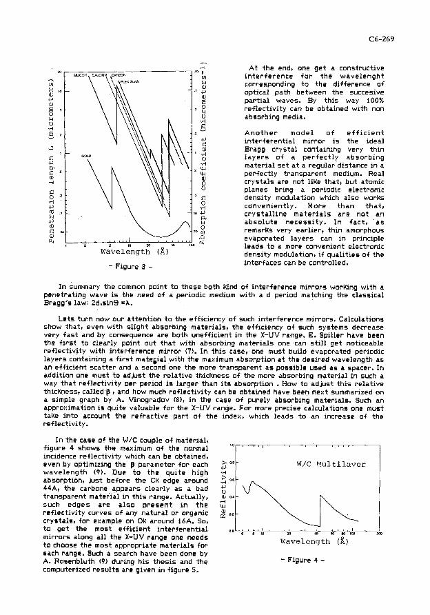
,--. -. A t the end, one get a constructive
in te r fe rence f o r the wavelenght corresponding t o the difference o f optical path between the succesive par t ia l waves. By th is way 100% ref lect iv i ty can be obtained w i th non absorbing media.
A n o t h e r mode l o f e f f i c i e n t in ter ferent ia l mirror i s the ideal Bragg crystal containing very th in l a y e r s o f a p e r f e c t l y absorb ing material set a t a regular distance i n a perfectly transparent medium. Real crystals are no t l ike that, b u t atomic planes bring a periodic electronic density modulation which also works convenient ly. More than that , c r y s t a l l i n e mate r ia l s are n o t an absolute necessity. I n fact , as remarks very earlier, th in amorphous evaporated layers can i n principle leads t o a more convenient electronic
Wavelength (X) density modulation, i f qual i t ies o f the
- Figure 3 - interfaces can be controlled.
I n summary the common point t o these both kind o f interference mirrors working wi th a penetrating wave i s the need o f a periodic medium wi th a d period matching the classical Bragg's law: 2d.sin43 =A.
L e t s tu rn now our attent ion t o the efficiency o f such interference mirrors. Calculations show that, even w i th s l ight absorbing materials, the efficiency o f such systems decrease very f a s t and by consequence are both uneff ic ient in the X-UV range. E. Spiller have been the f i r s t t o clearly po int ou t tha t w i t h absorbing materials one can s t i l l get noticeable ref lect iv i ty w i th interference mirror (7). I n t h i s case, one must bu i ld evaporated periodic layers containing a f i r s t matefial w i th the maximum absorption a t the desired wavelength as an ef f ic ient scatter and a second one the more transparent as possible used as a spacer. In addit ion one must t o adjust the re la t ive thicKness o f the more absorbing material i n such a way tha t re f lec t i v i t y per period is larger than i t s absorption . How t o adjust t h i s re la t ive thickness, called p , and how much ref lect iv i ty can be obtained have been next summarized on a simple graph by A. Vinogradov (g), i n the case o f purely absorbing materials. Such an approximation i s quite valuable f o r the X-UV range. For more precise calculations one must take i n t o account the refract ive par t o f the index, which leads t o an increase o f the ref lect iv i ty.
I n the case o f the W/C couple o f material, f igure 4 shows the maximum o f the normal
'" incidence re f lec t i v i t y which can be obtained, even by optimizing the p parameter fo r each 2 wavelength (9). Due t o the q u i t e h igh .d
absorption, just before the Ck edge around 5 44A, the carbone appears clearly as a bad $ transparent material i n t h i s range. Actually, a, 0.4
such edges are a lso p resen t i n the tu
re f lec t i v i t y curves o f any natural or organic 2 0.2
crystals, t o get the f o r example most e f f ic ient on Ok around in ter ferent ia l 16A. So, o,o
" " I
W/C Plultilaver
I,% 6 8 10 ZO (0 60 6 0 1 ~ 0 2m
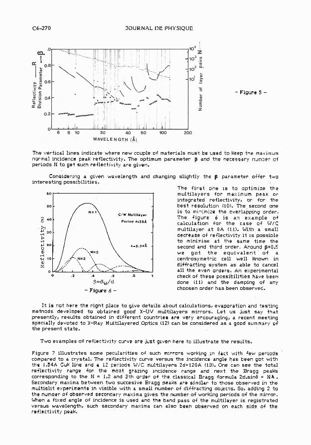
mirrors along a l l the X-UV range one needs t o choose the most appropriate materials f o r Wavelength (8) each range. Such a search have been done by A. Rosenbluth (9) during h i s thesis and the - Figure 4 - computerized resul ts are given in f igure 5.
JOURNAL DE PHYSIQUE
- Figure 5 -
" 6 8 1 0 20 40 60 100 200
WAVELENGTH (a]. The ver t ica l l i ne s indicate where new couple of mater ia ls must be used t o keep the maximum normal incidence peak reflectivity. The optimum parameter p and t h e necessary number of per iods N t o g e t such ref lec t iv i ty a r e given.
Conslderlng a glven wavelength and changlng sl ightly t h r p parameter o f f e r two ln teres t lng p o s s ~ b l l l t i e s .
The f l r s t o n e 1s t o optiml:e t h e m u l t l l a y e r s f o r maxlmum peak o r in tegra ted reflectivity, o r f o r t he bes t resolution fiO). The second one
C/W Multalayer 1s t o mlnlmize the overlapping order. The f i g u r e 6 1s a n example of
Perlod d=35& ' calculation f o r t h e c a s e of W/C multllayer a t %A ( i f) . With a smal l decrease of reflectivity ~t IS possible t o minimlse a t t he same time the second and thlrd order. Around p=0.5 we g o t t h e equivalent o f a centrosymetrlc cell well known In dlffractlng sys tem a s able t o cancel a l l t h e even orders . An experimental
o 2 .4 6 8 check of t h e s e poss lb l l l t ies have been 8=dw/d done (11) and t h e damping of any
- Figure 6 - choosen order h a s been observed.
I t i s not here t he r ight place t o give de t a i l s about calculations, evaporation and t e s t i ng methods developed t o obtained good X-UV multi layers mirrors. Let u s just s a y t h a t presently, r e s u l t s obtained in d i f f e r en t countries a r e very encouraging, a recent meeting specially devoted t o X-Ray Multilayered Optics i i 2 ) can be considered a s a good summary of the p re sen t s t a t e .
Two examples of reflectivity curve a r e just given here t o i l l u s t r a t e t he r e su l t s .
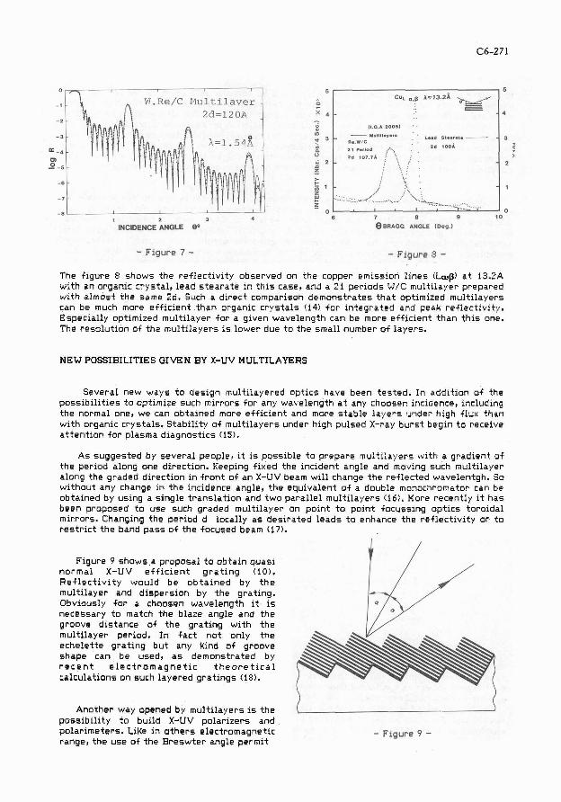
Figure 7 i l l u s t r a t e s some pecular i t ies of such mirrors working in f ac t with f ew per iods compared t o a crystal . The reflectivity curve ve r sus t he incidence angle h a s been go t with the 1.54A Cuk line and a 12 per iods W/C multi layers 2d=120A (13). One can s e e the t o t a l ref lec t iv i ty range f o r t h e most grazing incidence range and next t he Bragg peaks corresponding t o t he N = 112 and 3th order of t h e classical Bragg formula 2d.sin0 = N A . Secondary maxima between two succesive Bragg peaks a r e similar t o t hose observed in t he multisl i t experiments in visible with a small number of diffracting objects. So, adding 2 t o t he number of observed secondary maxima gives t he number of working periods of t he mirror. When a fixed angle of incidence is used and the band p a s s of t he multilayer i s regis t ra ted ve r sus wavelength, such secondary maxima can a l s o been observed on each s ide of t he ref lec t iv i ty peak.
INCIDENCE ANGLE BP 8 B R A G G ANGLE (Deg.)
- Figure 7 - - Figure 3 - The f igure 8 shows the ref lec t iv i ty observed on t h e copper emission l i nes iLa,pf a t i3.2A with an organic crys ta l , lead s t e a r a t e in t h i s case, and a 21 periods W/C multilayer prepared with a lmost t h e same 2d. Such a d i rec t comparison demonst ra tes t h a t optimized multi layers can be much more ef f ic ient t han organic c rys t a l s (14) f o r in tegra ted and peak reflectivity. Especially optimized multilayer fo r a given wavelength can be more ef f ic ient t han t h i s one. The resolut ion of t he multi layers is lower due t o t he small number of layers.
NEW POSSIBILITIES GIVEN BY X-UV MULTILAYERS
Several new ways t o design multilayered opt ics have been t e s t ed . In addit ion of t he poss ib i l i t ies t a aptirnize such mirrors f o r any wavelength a t any choosen incidence, including the normal one, we can obtained more ef f ic ient and more s t ab l e l aye r s under high flux than with organic crystals. Stabil i ty of multi layers under high pulsed X-ray bu r s t begin t o receive a t t en t ion f o r plasma diagnost ics (15).
As sugges ted by s eve ra l people, it is possible t o prepare multi layers with a gradient of t he period along one direction. Keeping fixed the incident angle and moving such multilayer along t h e graded direction in f ron t of an X-UV beam will change t h e reflected wavelentgh. So without any change in t he incidence angle, t h e equivalent of a double monochromator can be obtained hy using a s ingle t rans la t ion and two para l le l multi layers (16). More recently i t h a s been proposed t o u s e such graded multi layer on point t o point focussing opt ics toroidal mirrors. Changing the period d locally a s des i ra ted l eads t o enhance the reflectivity o r t o r e s t r i c t t h e band p a s s of t he focused beam 117).
Figure 9 shows a proposal t o obta in quas i normal X-UV e f f i c i e n t g r a t i n g (101. R e f l e c t i v i t y would be o b t a i n e d by t h e multilayer and dispers ion by the grating. Obviously f o r a choosen wavelength it IS necessary t o match the blaze angle and t h e groove d is tance of t h e gra t ing with t h e multilayer period. In f a d n o t only t h e echele t te gra t ing but any Rlnd of groove shape can be used, a s demonstrated by r e c e n t electromagnetic t h e o r e t i c a l calculations on such layered g r a t ~ n g s (18).
Another way opened by multi layers is t h e possibil i ty t o build X-UV polar izers and polarimeters. LiRe in o t h e r s electromagnetic - Figure 9 - range, t h e u se of the Breswter angle permit
JOURNAL DE PHYSIQUE
t o re f lect only one o f the component o f l i g t h and so t o polarize a beam by reflection. That happens f o r the incidence angle such tha t the refracted and the ref lected direct ion o f the wave are a t 90' . Because refract ive index i s almost the unity over a l l the X-UV range, the 45' incidence provide always a very good polarization rate as appears on the f igure 2. Unfortunatly, such a possibi l i ty i s forbidden w i th classical single interface mirrors because fo r such large angles the ref lect iv i ty efficiency i s too low. On the contrary, a multi layer optimized f o r such incidence can have good ref lect iv i ty and so t o be an effect ive polarizers. Possibi l i t ies o f X-UV polarizers and polarimeters have been demonstrated recently (6, 19).
Multi layered opt ics being able t o work a t the normal incidence, i s i n principle possible t o re turn t o the wel l known opt ical system using normal incidence mirror fo r telescope or microscope. Such poss ib i l i ty have been f i r s t tested a t 44.4A w i th a spherically bended si l icon wafer previously coated w i th a mult i layers (20). Schwarzchild microscope w i th two spherical confocal mirrors have been next designed fo r synchrotron source (21). Another example o f imaging multi layered optics i s the telescope bu i l t a t the I n s t i t u t d'optique d'Orsay fo r the french astrophysicists (22). I t i s a Ritchey-Chretien type system where aspherization o f the f i r s t mirror have been achieved by a graded single layer evaporated on the spherical blank before the mult i layer coating (23).
X-ray Fabry-Perot, first demonstrated by T. Barbee, i s an other major advance which must be underligned (24,25).
EXAMPLES OF THE USE OF MULTILAYERS FOR PLASMA DIAGNOSTICS
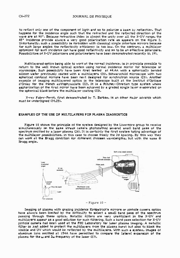
Figure 10 shows the principle o f the system designed by the L~vermore group t o receive simultaneously on the same streak camera photocathod several small band pass o f the spectrum emitted by a laser plasma (26). It i s certainly the f i r s t system t a k n g advantage of the mult i layer possibil it ies, i n t h i s case t o choose freely the 2d spacing. By t h i s way they can work a t the Bragg condition fo r d i f ferent choosen wavelengths, but w i th the same Q Bragg angle.
L- irradiated Drgt
L- irradiated Drgt
- Figure 10 -
Imaging o f plasma w i th grazing incidence KirKpatrick's mirrors o r pinhole camera optics have always been l imi ted by the d i f f icu l ty t o select a small band pass o f the spectrum passing through these optics. Metal l ic f i l t e r s are very uneff ic ient in the X-UV and mult i layers appear as a good solut ion f o r such f i l ter ing. Such a band pass selection f o r X-UV pinhole camera had been used a t the PM1 Laboratory fo r laser plasma imaging. A metall ic f i l t e r is j l s t added t o protect the mult i layers from the plasma burst but also t o block the visible and U V which would be ref lected by the multilayers. With such a system, images o f aluminum ions emitted a t i54A have permitted t o compare the la te ra l expansion o f the plasma fo r the W and 2w frequency o f the laser (27).
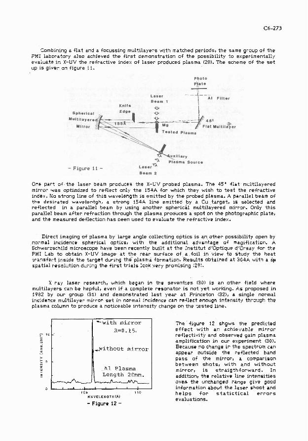
Combining a f l a t and a focussing multi layers with matched periods, t he same group of t he PM1 laboratory a l s o achieved t h e f i r s t demonstration of t h e possibil i ty t o experimentally evaluate in X-UV the ref rac t ive index of l a s e r produced plasma (28). The scheme of t h e s e t up is given on figure 11.
Laser AI F i l ter Beam 1
Knife
Spherical
--I--- Multi layere
Mirror
- Figure 11 - Beam 2
One pa r t of t he l a se r beam produces t he X-IJV probed plasma. The 45" f l a t multllayered mirror was optlmlzed t o r e f l ec t only the 154A fo r whlch they wlsh t o t e s t t he ref rac t ive index. No s t rong line of t h l s wavelength 1s emlt ted by t h e probed plasma. A para l le l beam of t he des i ra ted wavelentgh, a s t rong 154A l ine emitted b y a Cu t a rge t , 1s se lec ted and ref lec ted In a para l le l beam ny using another spherical multilayered mirror. Only t h i s para l le l beam a f t e r refraction through t h e plasma pruduces a s p o t on t h e photographic plate, and the measured deflection h a s been used t o evaluate t he refractive ~ n d e x .
Direct imaging of plasma by large angle collecting opt ics is an o the r possibil i ty open by normal incidence spherical opt ics , with t he addit ional advantage of magification. A Schwarzschild microscope have been recently buil t a t t he I n s t i t u t d'Optique dtOrsay f o r t he PM1 Lab t o obta in X-UV image a t t h e r e a r surface of a fo i l in view t o s tudy t h e heat t r a n s f e r t inside t h e t a r g e t during t h ~ . plasma formation. Resu l t s obtained a t 304A with a 6p spa t i a l resolution during the f i r s t t r i a l s look very promising ( 2 9 ) .
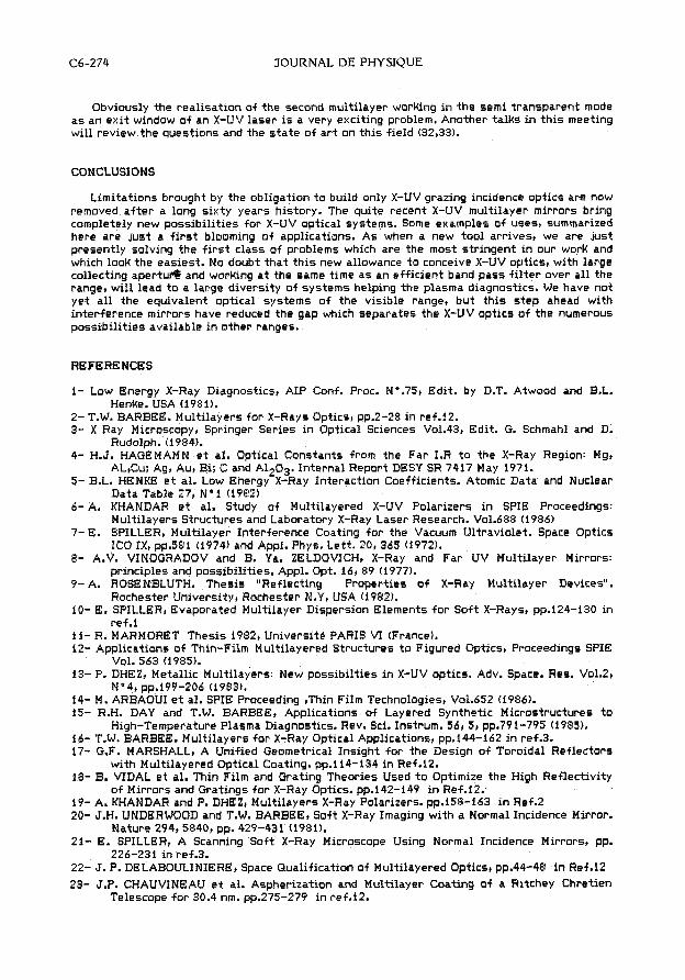
X ray l a s e r research, which began in the s even t i e s (30) is a n other f ield where multi layers can be hepful, even if a complete resonator is not y e t working. A s proposed in 1982 by our group (31) and demonstrated l a s t year a t Princeton 132), a s ingle normal incidence multilayer mirror set i n normal incidence can r e f l ec t enough in tens i ty through t h e plasma column t o praduce a noticeable in tens i ty change on the t e s t e d line.
0 1 l ' ! " ' l ! 1 105 1 1 0
W A V E L E N G T H C A )
- Figure 12 -
- 10
Z 3
m C 4
> t 5 V) Z Y
l-
?
The figure 12 shgws the predicted e f f e c t w i th a n ach ievab le mi r ro r reflectivity and observed gain plasma amplification in our experiment 130). Because no change in t he spectrum can appear outs ide the ref lec ted band p a s s of t he mirror, a comparison b e t w e e n s h o t s , wi th and w i t h o u t mi r ro r , is s t r a i g t h f o r w a r d . I n addition, t h e re la t ive l ine i n t ens i t i e s oven the unchanged range give good information about t h e l a s e r shoot and h e l p s f o r s t a t i c t i c a l e r r o r s evaluations.
- "with mirror
R = 0 . 1 5 ,
- -
-
+without mirror
A1 Plasma Length 2Gm. ,
C6-274 JOURNAL DE PHYSIQUE
Obviously the realisation of the second multilayer worUng in the semi transparent mode a s an exit window of an X-UV laser is a very exciting problem. Another talks in th i s meeting will review the questions and the s t a t e of a r t on th i s field (32,33).
CONCLUSIONS
Limitations brought by the obligation t o build only X-UV grazing incidence optics are now removed a f te r a long sixty years hlstory. The quite recent X-UV mult~layer mirrors bring completely new possibilities for X-UV optical systems. Some examples of uses, summarized here are just a f i r s t blooming of applications. As when a new tool arrives, we are just presently solving the f i r s t class of problems which are the most stringent in our work and which look the easiest. No doubt that th i s new allowance t o conceive X-UV optics, with large collecting apertu* and worKing a t the same time a s an efficient band pass f l l ter over all the ranget will lead t o a large diversity of systems helping the plasma diagnostics. We have not yet a l l the equivalent optical systems of the visible range, but th i s s tep ahead with interference mirrors have reduced the gap which separates the X-UV optics of the numerous possibilities available in other ranges.
REFERENCES
l- Low Energy X-Ray Diagnostics, AIP Conf. Proc. Ne.75, Edit. by D.T. Atwood and B.L. Henke. USA (1981).
2- T.W. BARBEE. Multilayers for X-Rays Optics, pp.2-28 in ref.12. 3- X Ray Microscopy, Springer Series in Optical Sciences Vo1.43, Edit. G. Schmahl and D.
Rudolph. 11984). 4- H.J. HAGEMAMN e t al. Optical Constants from the Far 1.R t o the X-Ray Region: Mgt
AL,Cu; Ag, Au, Bi; C and Al,03. Internal Report DESY SR 7417 May 1971. 5- B.L. HENKE e t al. Low ~nergy-X- ay Interaction Coefficients. Atomic Data and Nuclear
Data Table 27, N'1 11982) 6- A. KHANDAR e t al. Study of Multilayered X-UV Polarizers in SPIE Proceedings:
Multilayers Structures and Laboratory X-Ray Laser Research. Vo1.688 (1986) 7- E. SPILLER, Multilayer Interference Coating for the Vacuum Ultraviolet. Space Optics
ICO I X , pp.581 (1974) and Appl. Phys. Lett. 20,365 (1972). 8- A.V. WNOGRADOV and B. Ya. ZELDOWCHt X-Ray and Far UV Multilayer Mirrors:
principles and possibilities. Appl. Opt. 16, 83 (1977). 9- A. ROSENBLUTH. Thesis "Reflecting Properties of X-Ray Multilayer Devices".
Rochester University, Rochester N.Y, USA (1982). 10- E. SPILLER, Evaporated Multilayer Dispersion Elements for Soft X-Rays, pp.124-130 in
ref.1 11- R. MARMORET Thesis 1982, Universite PARIS V1 (France). 12- Applications of Thin-Film Multilayered Structures t o Figured Optics, Proceedings SPIE
Vol. 563 11985). 13- P. DHEZ, Metallic ~ u l t i l a y e r s : New possibilties in X-UV optics. Adv. Space. Res. V01.2,
Ne4, pp.!99-206 (1983). 14- M. ARBAOUI e t al. SPIE Proceeding ,Thin Film Technologies, Vo1.652 11986). 15- R.H. DAY and T.W. BARBEE, Applications of Layered Synthetic Microstructures t o
High-Temperature Plasma Diagnostics. Rev. Sci. Instrum. 56,5, pp.791-795 (1985). 16- T.W. BARBEE. Multilayers for X-Ray Optical Applications, pp.144-162 in ref .3. 17- G.F. MARSHALL, A Unified Geometrical Insight for the Design of Toroidal Reflectors
with Multilayered Optical Coating. pp.114-134 in Ref.i2. 18- B. VIDAL e t al. Thin Film and Grating Theories Used t o Optimize the High Reflectivity
of Mirrors and Gratings for X-Ray Optics. pp.142-149 in Ref.12.- 19- A. KHANDAR and P. DHEZ, Multilayers X-Ray Polarizers. pp.158-163 in Ref.2 20- J.H. UNDERWOOD and T.W. BARBEE, Soft X-Ray Imaging with a Normal Incidence Mirror.
Nature 294,5840, pp. 429-431 1198 l). 21- E. SPILLER, A Scanning Soft X-Ray Microscope Using Normal Incidence Mirrors, pp.
226-231 in ref.3. 22- J. P. DELABOULINIERE, Space Q.ualification of Multilayered Optics, pp.44-48 in Ref.12
23- J.P. CHAUVINEAU e t al. Aspherization and Multilayer Coating of a Ritchey Chretien Telescope for 30.4 nm. pp.275-279 in ref.12.
24- T.W. BARBEE e t al. Solid Fabry-Perot Etalons for X-Rays. Opt. Comm.4'3,3,161 (1983). 25- Y. LEPETRE e t al. Fabry-Perot Etalons for X-Rays: Construction and Characteristics.
Opt. Comm.S1,3,i27 (1984). 26- G.L. STRADLING e t al. Strealred Spectrometry using Multilayer X-Ray Interference
Mirrors t o Investigate Energy Transport in Laser Plasma Applications. pp.292- 296. in ref. l.
27- R. BENATTAR and J. GODART, Characterization of the Thermal Front ~ n s i d e a 2w Laser Produced Plasma by it Emission in the X-UV Range. Opt. Comm. 51, 4; pp.260 (1984).
28- R. BENATTAR and J. GODART, Evidence of Soft X-Ray Refraction Induced by a Laser Produced Plasma. Opt. Comm. 56, 6, pp. 418-424 (1986).
29- R. BENATTAR e t al. A Schwarzschild Microscope t o Study the Preheat of Laser Heated Targets. in SPIE Proceedings "Multilayers Structures and Laboratory X-Ray Laser Research". Vo1.688 (1986)
30- P. JAEGLE e t al. Experimental Evidence for the possible Existence of a Stimulated Emission in the Extreme U.V Range. Phys. Lett. Vo1.36At PP.167-168 (197 11.
31- P. DHEZ e t al. X-UV Gain Amplification Studies in Laser Plasma Using Normal Incidence Multilayers Mirror, AIP Conf. Proceedings N'119. Am. Inst. of Phys. "Laser Techniques in the Extreme Ultraviolet" pp.199-206 (1984).
32- S. SUCKEWER e t al. Amplification of Stimulated Soft X-Ray Emission in a Confined Plasma Column, Phys. Rev. Lett. Vo1.55, pp.i753-1756 (1985).
33- J. TREBES, X-Ray Laser Cavities. This colloquium. 34- A.V. VINOGRADOV, The Optics for Pumping and Cavities of X-UV Laser. Thls colloquium.