Embed Size (px)
Citation preview

C60/C67 HPW
1/2“
- 13
5 (5
,33“
)3/
4“ -
140
(5,5
3“)
69 (2
,72“
)
X Z
Y
6
1
24 3
5
1
ConstructionThe GEMÜ CleanStar® C60 / C67 HPW ultra pure pneumatically or manu-ally operated 3/5 way diaphragm valves have a full PFA-HP body with two valve seats. All medium wetted parts are in PFA-HP or PTFE (diaphragm). The non-wetted bonnet is PVDF. The standard version of type C60 (pneumatic) is designed as a diverter valve: 1 x NC and 1 x NO (2 pneumatic actuators C60, one normally closed, one normally open). C60 has a stroke limiter and an optical position indica-tor (1), C67 (manual) has a travel stop (6) as standard. Solid mounting lugs (2) are integrated and there is also a connection for a leakage detection sensor (3). The union nuts can be either in PVDF-HP, PFA-HP or C-PFA-HP (4). C67 has a standard optical position indicator (5).
Advantages• Minimal deadleg• High Kv values • Optional flow direction• Can be used as a media blending valve• Actuators can be independently controlled• Can be fully integrated with existing GEMÜ process controls
CleanStar® 3/5 WayPFA Diaphragm Valves
GEMÜ CleanStar® 3 way valve C60(pneumatic/pneumatic)
GEMÜ CleanStar® 3 way valve C60 (pneumatic/manual)
GEMÜ CleanStar® 3 way valve C67(manual/manual)
Dimensions GEMÜ C60 3 way valve (pneumatic/pneumatic) [mm/inch]

2C60/C67 HPW
X Z
YC60 C60
X Z
YC60 C67
X Z
YC67 C60
X Z
YC67 C67
Code 1, 2, D, G, H Code F, K
Code A, B Code 0
Range Overview CleanStar® C60/C67 3 way valves
Type of connection / Availability SizeFlare
connectionButt-weld spigots
Space saver Connection
Actu
ator
si
ze
Pos. X + Z Pos. Y Pos. X + Z + Y
Cod
ein
tern
atio
nal
DN
Z
Y
X Z
Y
X Z
Y
X Z
Y
X Z
Y
X Code
1/2“ - 1/2“ - 1/2“ 8 102
3/4“ - 3/4“ - 3/4“ 12 15on requeston request
on requeston request
Control function Valve 1 (X - Y) Valve 2 (Z - Y)
Type Control function Type Control function CodeC60 Normally closed C60 Normally closed 1C60 Normally closed C60 Normally open DC60 Normally closed C67 Manually operated FC60 Normally open C60 Normally open 2C60 Normally open C60 Normally closed GC60 Normally open C67 Manually operated KC60 Normally open C60 Double acting HC67 Manually operated C60 Normally closed AC67 Manually operated C60 Normally open BC67 Manually operated C67 Manually operated 0
Valve 1 Valve 2
Valve 1 Valve 2
Valve 1 Valve 2
Valve 1 Valve 2

C60/C67 HPW4
Control Air Volume - C60Actuator size Control function Actuator Volume [cm³]
2
1 Normally closed 24.02 Normally open 39.03 Double acting (closed) 39.03 Double acting (open) 24.0
Kv / Cv valuesConnection Size Kv Cv
Size Connection Code Code international DN Actuator l/min US gal/min
1/2” tube Flare connection 75 and 77 8 10 2 28 2.03/4” tube Flare connection 75 and 77 12 15 2 53 3.7
Technical Data
MaterialsMedium wetted parts (body) PFADiaphragm PTFEBonnet parts, non-wetted PVDF
Control pressure (only C60)“Normally closed” (c.f. 1) 4-7 bar“Normally open” (c.f. 2) max. 4 bar and “double acting” (c.f. 3)
Control air connection (only C60)Size G 1/8
Flow mediumSuitable for any inert or corrosive gases or liquids,-especial-ly high purity media- which do not corrode the respective body and diaphragm materials.
Flow directionOptional
Operating temperatureSee temperature/pressure diagram on page 4
Ambient temperatureMax. 60°C (130°F)
Operating pressureMax. 6 bar when applied upstream onlyVacuum 400 mbar/abs** The life expectancy of the valve may be affected if exposed to a greater vacuum.
Position space saver (optional)Space saver X-position Space saver Y-position Space saver Z-position Space saver X+Z-position
Z
Y
X Code X Z
Y
X Code Y Z
Y
X Code Z Z
Y
X Code S
C60/C67 HPW 3
* Connections are limited to versions with same nominal sizes at all positions. Size variations to follow.
5 Connection type (Connection Y) CodeFlare connection with C-PVA union nut 73 (also for space saver)Flare connection with PVDF union nut 75 (also for space saver)Flare connection with PFA union nut 77 (also for space saver)
11 Nominal size (connections X + Z) Code1/2“ tube DN 10 83/4“ tube DN 15 12
12 Connection type (connections X+ Z) CodeFlare connection with C-PVA union nut 73 (also for space saver)Flare connection with PVDF union nut 75 (also for space saver)Flare connection with PFA union nut 77 (also for space saver)
Order data
3 Nominal size (Connection Y) Code1/2“ tube DN 10 83/4“ tube DN 15 12
4 Body geometry CodeV body V
6 Body material CodePFA 30
7 Diaphragm material CodePTFE 5A
2 Position of space saver (optional) CodeSpace saver in X-position XSpace saver in Y-position YSpace saver in Z-position ZSpace saver in X+Z-position S
9 Bonnet version CodeBonnet size 2 2
1 Type CodeC60 - Valve 1 (X - Y) C60C67 - Valve 1 (X - Y) C67
Order example 1 2 3 4 5 6 7 8 9 10 11 12 13C60 Y 8 V 75 30 5A F 2 S 8 75 HPW
10 Position Space saver (optional) CodeSpace saver X-position XSpace saver Y-position YSpace saver Z-position ZSpace saver X+Z-position S
13 Body geometry CodeV body V
8 Control function CodeC60 / C60 (Normally closed/Normally closed) 1C60 / C60 (Normally closed/Normally open) DC60 / C67 (Normally closed/Manually operated) FC60 / C60 (Normally open/Normally open) 2C60 / C60 (Normally open/Normally closed) GC60 / C67 (Normally open/Manually operated) KC60 / C60 (Normally open/Double acting) HC67 / C60 (Manually operated/Normally closed) AC67 / C60 (Manually operated/Normally open) BC67 / C67 (Manually operatedt/Manually operated) 0
C60/C67 HPW4
-4 14 32 50 68 86 104 122 140 158 176 194 212 230 248 266 284 302
-20 -10 0 10 20 30 40 50 60 70 80 90 100 110 120 130 140 150
7
6
5
4
3
2
1
105
90
75
60
45
30
15
A
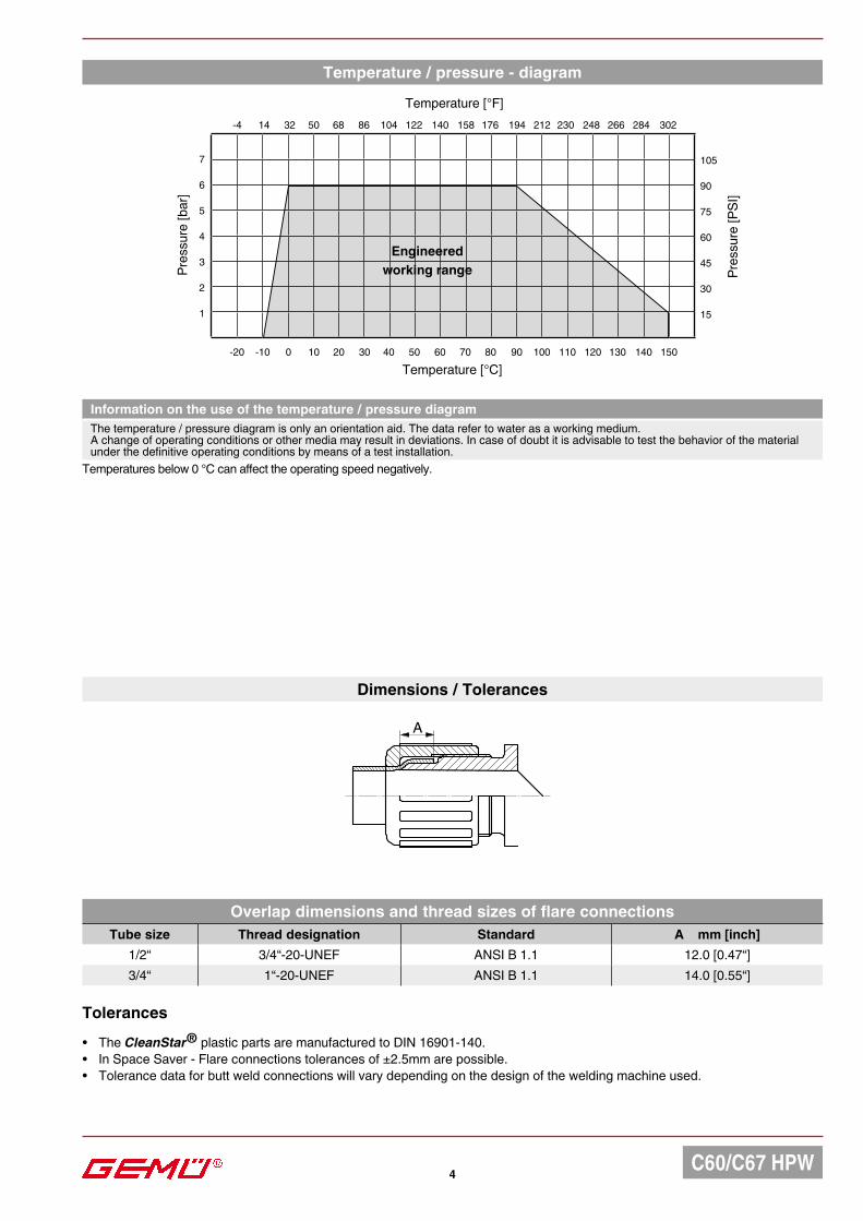
Temperature / pressure - diagram
Temperature [°C]
Temperature [°F]
Pres
sure
[PSI
]
Pres
sure
[bar
]
Engineeredworking range
Tolerances
• The CleanStar® plastic parts are manufactured to DIN 16901-140.• In Space Saver - Flare connections tolerances of ±2.5mm are possible.• Tolerance data for butt weld connections will vary depending on the design of the welding machine used.
Information on the use of the temperature / pressure diagramThe temperature / pressure diagram is only an orientation aid. The data refer to water as a working medium. A change of operating conditions or other media may result in deviations. In case of doubt it is advisable to test the behavior of the material under the definitive operating conditions by means of a test installation.
Dimensions / Tolerances
Overlap dimensions and thread sizes of flare connectionsTube size Thread designation Standard A mm [inch]
1/2“ 3/4“-20-UNEF ANSI B 1.1 12.0 [0.47“]3/4“ 1“-20-UNEF ANSI B 1.1 14.0 [0.55“]
Temperatures below 0 °C can affect the operating speed negatively.

C60/C67 HPW 5
69 (2
,72“
)
X Z
Y1/
2“ -
135
(5,3
3“)
3/4“
- 14
0 (5
,53“
)
X
Y
Z69
(2,7
2“)
1/2“
- 13
5 (5
,33“
)3/
4“ -
140
(5,5
3“)
X Z
Y
1/2“
- 13
5 (5
,33“
)3/
4“ -
140
(5,5
3“)
Dimensions - GEMÜ C60 3 way valves (pneumatic/manual) [mm/inch]
Dimensions - GEMÜ C67 3 way valves (manual/manual) [mm/inch]

Tech
nica
l Dat
ashe
etSu
bjec
t to
mod
ificat
ion
· 09/
2016
· 88
2240
35Sh
ould
ther
e be
any
dou
bts o
r misu
nder
stand
ings,
the
Ger
man
vers
ion o
f this
data
shee
t is th
e au
thor
itativ
e do
cum
ent!
GEMÜ C67 STAService tool for actuators
GEMÜ 1098Flaring mandrel
GEMÜ CF STFService tool for flare union nuts
Accessories
GEMÜ C67 LODLock out device
VALVES, MEASUREMENTAND CONTROL SYSTEMS
GEMÜ Gebr. Müller · Apparatebau GmbH & Co. KG · Fritz-Müller-Str. 6-8 · D-74653 Ingelfingen-Criesbach · Tel. +49 (0) 7940/123-0 · Telefax +49 (0) 7940/[email protected] · www.gemue.de