Embed Size (px)
Citation preview

XAPPER UpdateXAPPER Update
Presented by: Jeff Latkowski
XAPPER Team: Ryan Abbott, Brad Bell, and Keith Kanz Special thanks to: Stan Ault
HAPL Program WorkshopOak Ridge National Laboratory
March 21-22, 2006UCRL-219931-PRES
Work performed under the auspices of the U. S. Department of Energy byLawrence Livermore National Laboratory under Contract W-7405-Eng-48.

XAPPERXAPPER
JFL 03/21/06
Progress since the last meeting
Thermometer trials and tribulations
Plans for using XAPPER to expose optics
XAPPERXAPPER
JFL 03/21/06
The original thermometer has notworked for us for a variety of reasons
Original system used 200 m fiber with 75 and 40 mm lenses:
Gave a 375 m diameter field of view
XAPPER has a small spot size of~440 m diameter
Gave temperature variations in field of view (a definite no-no for optical pyrometry)
Switched optics to 62 and 150 mm lenses:
Field of view reduced to 83 m
Increased edge temperature to2450 ºC
Reduced field of view cuts signal by 20x, but 46% more solid-angle
Overall signal reduction of 14x
0.0
0.2
0.4
0.6
0.8
1.0
0 100 200 300 400 500
Spot radius (m)
Inte
nsi
ty (
a.u
.)
fieldof
view
Tpeak = 2500ºC
T83m = 2450ºC
T187m = 1510ºC
XAPPERXAPPER
JFL 03/21/06
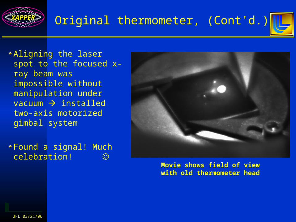
Original thermometer, (Cont'd.)
Aligning the laser spot to the focused x-ray beam was impossible without manipulation under vacuum installed two-axis motorized gimbal system
Found a signal! Much celebration!
Movie shows field of view with old thermometer head

XAPPERXAPPER
JFL 03/21/06
Original thermometer, (Cont'd.)
We moved onto a new sample to start collecting real data signal was gone!
Discovered that the heavily damaged sample had been reflecting pinch light into the thermometer head
Confirming experiment: blocked EUV beam with a plate of glass and still saw same (visible light) signal

XAPPERXAPPER
JFL 03/21/06
Spectrum from the Astron
0
200
400
600
650 750 850 950 1050 1150
Wavelength (nm)
Inte
ns
ity
(a
.u.)
We have tried various fixes
Look for a dead-zone in the spectrum doesn't appear to be one
Temporal discrimination between pinch and emitted light pinch light persists too long
Vary angles not a real option (can’t get shallower angle; blackbody emission is lambertian, so signal would fall rapidly at steeper angles)
Look at the back side of a thin sample inadequate space
All of these options assume that we have a good signal that gets drowned out by reflected
pinch light. Instead, we see nothing until the material
damages. Suppressing the pinch light won’t fix the
underlying problem.

XAPPERXAPPER
JFL 03/21/06
Original thermometer, (Cont'd.)
3um_cold Front3um_cold Back3um_cold Front3um_cold Back
t (s)
T (
K)
10-9 10-7 10-5 10-3 10-1
3500
3000
2500
2000
1500
1000
Use thin sample (<5 m) to keep material hot for "long" time (milliseconds):
Sit at lower temperature, lose by T4 (12-18x)
Able to count for ~1ms instead of ~100ns, win big (104x)
Unfortunately, the ripples inherent to a thin foil are quite similar to those resulting from surface damage we immediately see reflected pinch light

XAPPERXAPPER
JFL 03/21/06
Original thermometer, (Cont'd.)
Why doesn’t it work for us? Signal strength is just too low:
700/800nm aren’t the best wavelengths for our target temperatures; plus, small spread forces narrow bandpass (10 vs. 40nm) filters, further reducing the possible signal
Simple analysis shows that blackbody emission getting to thermometer head (with Lambertian distribution) is only 1400-2100 p/ns in each band
Emissivity probably ~0.3 and filters transmission is ~50%, so we have200-300 p/ns
Uncoated fiber ends (and possibly optics) result in further reductions
1.E+09
1.E+10
1.E+11
1.E+12
1.E+13
0 500 1000 1500 2000 2500 3000 3500 4000
Wavelength (nm)
Inte
ns
ity
(a
.u.)
600C
1000C
1500C
2000C
2500C

XAPPERXAPPER
JFL 03/21/06
We’ve moved to a 6-color pyrometerusing LN-cooled photodiodes
System is borrowed from Stan Ault of LLNL’s B Division – thanks Stan!System operates with 6 fibers (actually 7 in all) at 1.25, 1.65, 2.11, 2.71, 3.28 and 4.08 mSiO2 fibers for the two lower ’s and chalcogenide at higher ’sCoated ZnSe lenses for transmission at higher ’s and lower Fresnel lossesLN-cooled Kolmar photodiodes with 25ns rise time/50ns fall timePD’s are set up with pre-amplification circuitCalibrated with blackbody source (not a ratio-temp lamp like for the old system)
Able to see calibration signal at 700C with lamp with aperture down to318 m
We have been unable to actually implement in the XAPPER chamber due to very fragile fiber and stiff protective casing
We have operated calibration system near XAPPER while it has been running (electrical noise doesn’t appear to be a problem)

XAPPERXAPPER
JFL 03/21/06
We plan to construct our own, many-color pyrometer tuned to our needs
Use Kolmar’s smaller (0.5mm vs. 1mm) photodiodes to get faster response (7ns rise/~14ns fall) and faster amplifier w/ higher gain
Go to one single crystal sapphire fiber more signal than with bundle and able to span range:
In current system, each fiber gets only 1/9 of signal put on bundle
With single fiber, we can afford up to 89% signal loss due to increased fiber attenuation and beamsplitting before signal is as low as it is for current bundle
vs.
XAPPERXAPPER
JFL 03/21/06
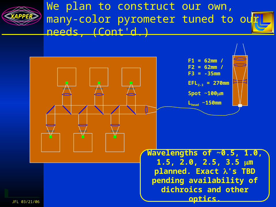
We plan to construct our own, many-color pyrometer tuned to our needs, (Cont'd.)
F1 = 62mm /F2 = 62mm /F3 = -35mm
EFL2-3 = 270mm
Spot ~100m
Lhead ~150mm
Wavelengths of ~0.5, 1.0, 1.5, 2.0, 2.5, 3.5 m planned. Exact 's TBD pending availability of
dichroics and other optics.
XAPPERXAPPER
JFL 03/21/06
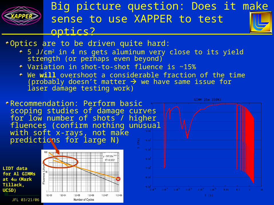
Big picture question: Does it makesense to use XAPPER to test optics?
Optics are to be driven quite hard:5 J/cm2 in 4 ns gets aluminum very close to its yield strength (or perhaps even beyond)Variation in shot-to-shot fluence is ~15%We will overshoot a considerable fraction of the time (probably doesn’t matter we have same issue for laser damage testing work)
Recommendation: Perform basicscoping studies of damage curvesfor low number of shots / higherfluences (confirm nothing unusualwith soft x-rays, not makepredictions for large N)
1 108
1 107
1 106
1 105
1 104
1 103
0.01 0.1 1 109 10
7
8 107
7 107
6 107
5 107
4 107
3 107
2 107
1 107
0
GIMM 26m 350MJ
t (s)
S (P
a)
Laser
x-rays
Debris Ions
Burn Ions
LIDT data for Al GIMMs at 4Mark Tillack, UCSD)
XAPPERXAPPER
JFL 03/21/06
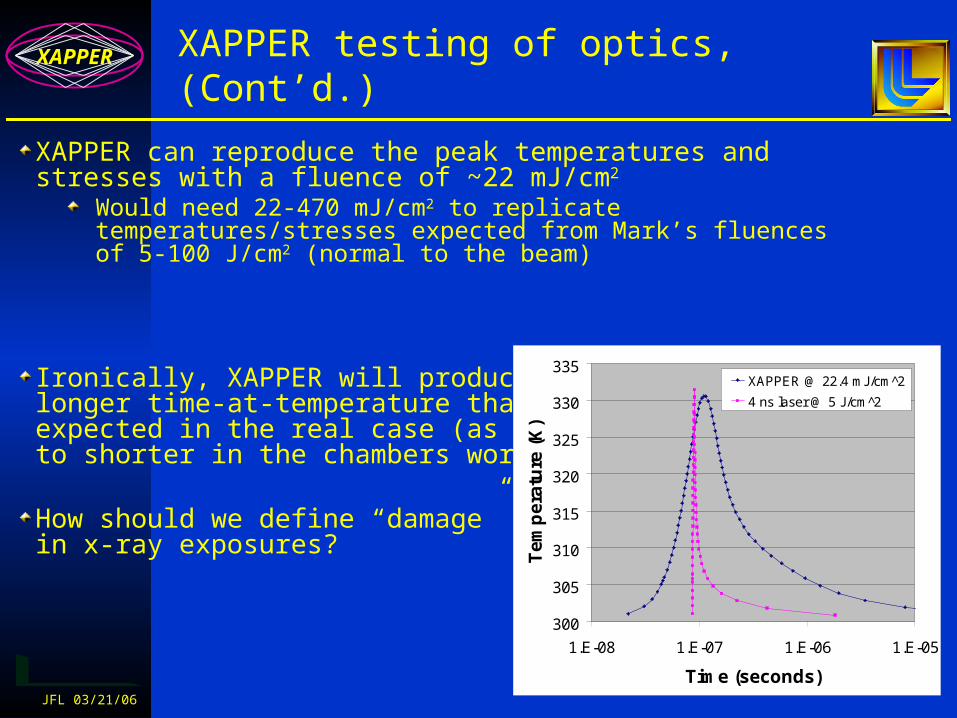
XAPPER testing of optics, (Cont’d.)
XAPPER can reproduce the peak temperatures and stresses with a fluence of ~22 mJ/cm2
Would need 22-470 mJ/cm2 to replicate temperatures/stresses expected from Mark’s fluences of 5-100 J/cm2 (normal to the beam)
Ironically, XAPPER will producelonger time-at-temperature thanexpected in the real case (as opposedto shorter in the chambers work)
How should we define “damage”in x-ray exposures?
300
305
310
315
320
325
330
335
1.E-08 1.E-07 1.E-06 1.E-05
Time (seconds)
Te
mp
era
ture
(K
)
XAPPER @ 22.4 mJ/cm^2
4 ns laser @ 5 J/cm^2
XAPPERXAPPER
JFL 03/21/06
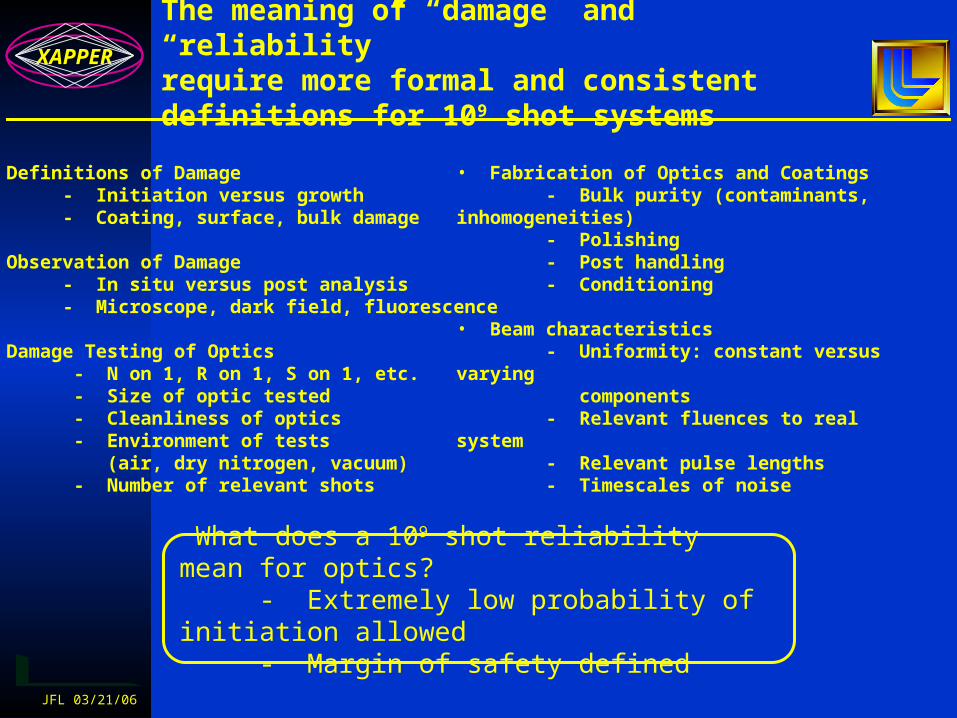
The meaning of “damage” and “reliability”require more formal and consistentdefinitions for 109 shot systems
• Definitions of Damage - Initiation versus growth - Coating, surface, bulk damage • Observation of Damage - In situ versus post analysis - Microscope, dark field, fluorescence
• Damage Testing of Optics - N on 1, R on 1, S on 1, etc. - Size of optic tested - Cleanliness of optics - Environment of tests (air, dry nitrogen, vacuum) - Number of relevant shots
• Fabrication of Optics and Coatings - Bulk purity (contaminants, inhomogeneities) - Polishing - Post handling - Conditioning
• Beam characteristics - Uniformity: constant versus varying components - Relevant fluences to real system - Relevant pulse lengths - Timescales of noise
What does a 109 shot reliability mean for optics? - Extremely low probability of initiation allowed - Margin of safety defined

XAPPERXAPPER
JFL 03/21/06
We are developing detailed modelsthat consider availability and reliabilityover the lifetime of an IFE plant
Max of N analysis indicates small change in fluence for a large numbers of shots
Bundling/Multiplexinggeometries influence availability
We think it’s time to gather the “optics” folks and form a working group to exchange ideas and establish similar
IFE reliability protocols for testing and analysis
XAPPERXAPPER
JFL 03/21/06
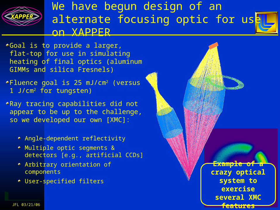
We have begun design of an alternate focusing optic for use on XAPPER
Goal is to provide a larger, flat-top for use in simulating heating of final optics (aluminum GIMMs and silica Fresnels)
Fluence goal is 25 mJ/cm2 (versus1 J/cm2 for tungsten)
Ray tracing capabilities did not appear to be up to the challenge, so we developed our own [XMC]:
Angle-dependent reflectivity
Multiple optic segments & detectors [e.g., artificial CCDs]
Arbitrary orientation of components
User-specified filtersExample of a crazy optical system to exercise several
XMC features

XAPPERXAPPER
JFL 03/21/06
Using XMC, we have simulatedXAPPER's current optical system
Sensitivity studies have been completed for optic alignment (r, z, )
Radial displacement Axial displacement Zenith tilt
These images look very similar to what we actually see on our CCD. This gives us
confidence that the code is working properly.

XAPPERXAPPER
JFL 03/21/06
We are now using XMC to designthe new focusing optic
We hope to combine multiple optical segments to provide something resembling a flat top
10 mJ delivered should be possibleAt 50 mJ/cm2 (2x fluence goal), could use spot size of 5 mm diameter
Once optical design is finalized, completed optic could be delivered in 6-8 weeks
Complications:Fluence measurements will require thinner CCD filters more expensive, more fragile and subject to pinholesThere’s no hope for an actual temperature measurement must rely upon modeling and fluence measurements

XAPPERXAPPER
JFL 03/21/06
Future plans
Detailed design, procurement and assembly for the 6-color pyrometer
Additional tungsten exposures:
Goal is many spots on same sample with temperature measurementsExposure of nanocrystalline tungsten samples
Dr. Snead has promised to provide SiC samples soon
Final design, fabrication and testing for alternate XAPPER optic

Photo credit: Ryan AbbottPhoto credit: Ryan AbbottPilot: Jeff LatkowskiPilot: Jeff Latkowski
Questions?

Back-up slidesBack-up slides

XAPPERXAPPER
JFL 03/21/06
Source designed / built by PLEX LLC
Operates with xenon gas pinch to produce 80-150 eV x-rays
Operation possible at up to 10 Hz for millions of pulses
Condensingoptic
Materialsample
Plasmapinch
The XAPPER experiment is used to studydamage from rep-rated x-ray exposure

62mm and150mm lenses
Condensingoptic
Thermometerhead
Plasmapinch
Sampleplane
XAPPERXAPPER
JFL 03/21/06
XAPPER’s mission is to investigate cyclic fatigue and other “sub-threshold” effects
XAPPER is looking for “sub-threshold” (e.g., without melting or ablation) effects such as roughening and thermomechanical fatigue.
XAPPER cannot match the x-ray spectrum, but it can replicate a selected figure of merit (e.g., peak surface temperature, dose, stress, etc.).
XAPPER is used in the study of x-ray damage to chamber wall materials and will be applied to optics in the near future.
Our results to date show some roughening of tungsten, but we do not see anything that would
suggest the first wall armor concept would not work.