Embed Size (px)
DESCRIPTION
arduino
Citation preview
How-to: Setting up XBee ZNet 2.5 (Series 2) modules The XBee ZNet 2.5 modules from Digi are more advanced than the popular XBee Series 1 modules, but they require a little additional work to set up. This tutorial will guide you through reflashing two XBee ZNet modules with the appropriate firmwares and setting them up to communicate with eachother.
Materials needed: 2 - XBee ZNet 2.5 Modules (Digikey Part#: XB24-BWIT-004-ND)
1 - XBee Breakout Board (Sparkfun SKU#: BOB-08276 or from NKC Electronics)
2 - 2mm, 10 pin XBee socket (Sparkfun SKU#: PRT-08272 or included with NKC kit)
1 - Male Header row for XBee breakout (Sparkfun SKU#: PRT-00117 or included with NKC kit)
1 - FT232RL Breakout Board (Sparkfun SKU#: BOB-00718)
- male or female headers for the FT232RL Breakout board, depending on your preference
2 – LEDs
1 – Reset Switch (optional, see below)
Breadboard
Jumper wires (I prefer the fancy ones from Sparkfun (PRT-08430 and PRT-08431), but any 22awg solid
wire will work)
USB miniB cable
Arduino Diecimila
XBee Shield from NKC Electronics (http://www.nkcelectronics.com/freeduino-arduino-xbee-shield-kit.html)
A computer running Windows
Also recommend: 3.3V Power Supply – Sparkfun SKU#: PRT-00114 is handy, but you can also just rig up your own 3.3V
regulator
An XBee ZNet 2.5 Module with Sparkfun’s XBee breakout board
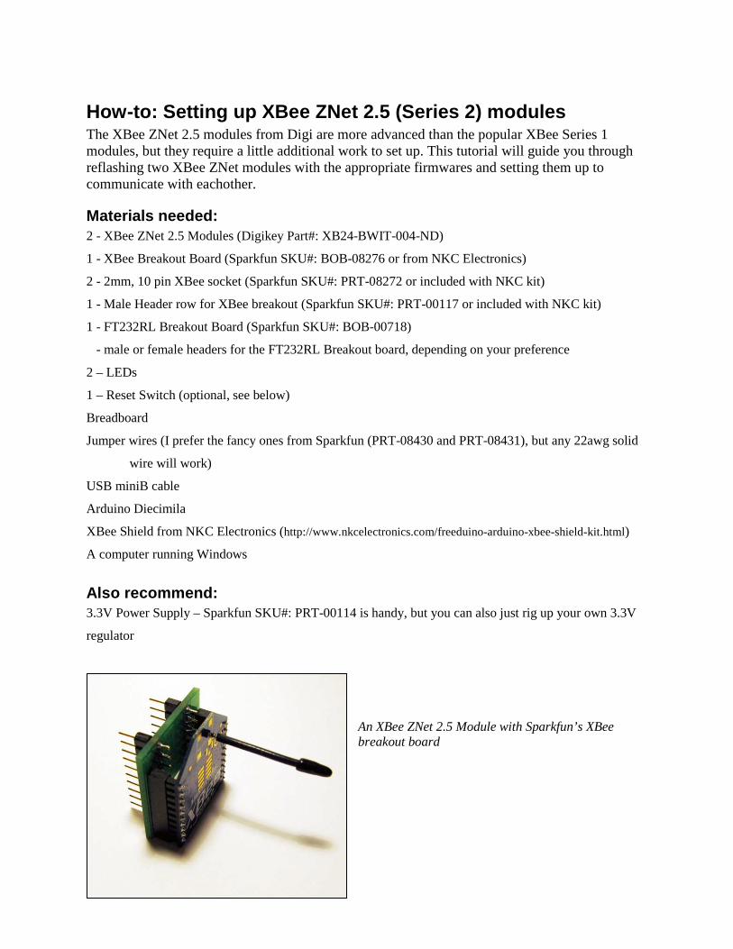
Step 1: Construct the circuit Build the XBee Breakout board and plug one of the XBee’s into it. Set up the circuit on your bread board using the diagram. Instead of using a reset switch, I just plug one end of a jumper wire into the XBee reset pin and leave the other end of that jumper hanging off the edge of the board; when I need to reset the XBee, I just momentarily touch the bare end of the jumper to ground.
Note: The FT232RL provides a maximum of 50mA on the 3.3V pin. The XBee ZNet modules pull a max of 40mA, so you should be ok. However, if you are using the XBee Pro version, you may need to use an external 3.3V supply.
Step 2: Power-up the XBee and prep the software After double checking your connections, use the USB-miniB cable to plug the FT232 Breakout into a USB port on your computer. Both LEDs connected to the XBee should light up and stay on (assuming your XBee shipped as a Router/End Device and there is no Coordinator around to connect to). Download the X-CTU software from Digi and install it. The software can be downloaded from http://www.digi.com/support/productdetl.jsp?pid=3261&osvid=57&tp=4&s=269
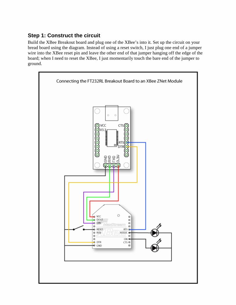
Step 3: Run X-CTU and connect to the XBee Run the X-CTU software. You should see a screen like the one to the right. Single-click on the USB COM port that the XBee is connected to. If you’re not sure, you can click the “Test/Query” button to read each COM port to discover which one has the XBee.
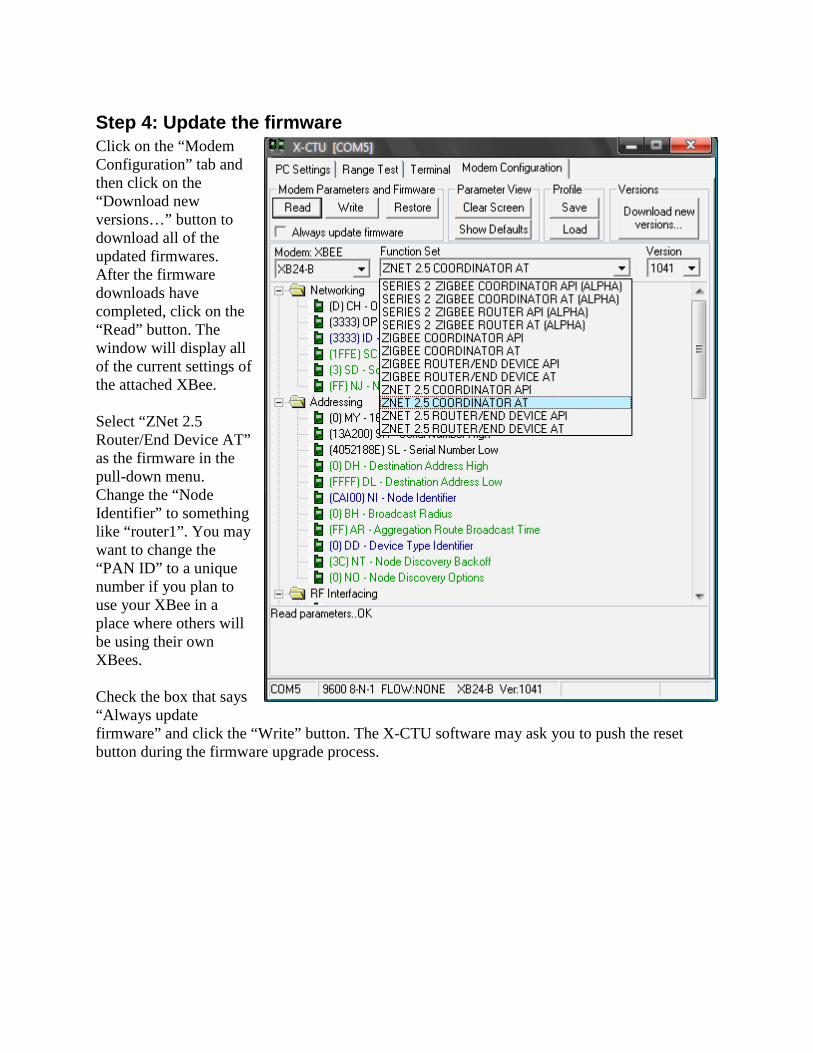
Step 4: Update the firmware Click on the “Modem Configuration” tab and then click on the “Download new versions…” button to download all of the updated firmwares. After the firmware downloads have completed, click on the “Read” button. The window will display all of the current settings of the attached XBee. Select “ZNet 2.5 Router/End Device AT” as the firmware in the pull-down menu. Change the “Node Identifier” to something like “router1”. You may want to change the “PAN ID” to a unique number if you plan to use your XBee in a place where others will be using their own XBees. Check the box that says “Always update firmware” and click the “Write” button. The X-CTU software may ask you to push the reset button during the firmware upgrade process.

Step 5: Test the XBee Read through this step before you do it since once you enter command mode, you’ll need to enter a new command within 5 seconds or the XBee will exit command mode and you’ll need to start this step again. Click on the terminal tab and type “+++” in the window to enter command mode. The XBee should respond in a second or two with “OK”. Type “ATVR” to check the firmware version on the XBee. This should match the firmware version that you upgraded to (1241 for Router/End Device or 1041 for Coordinator). Type “ATID” to check the PAN Network ID that the XBee is using. It should respond with “123” or whatever unique PAN ID you set in step 4. Type “ATNI” to check the Node Identifier. The XBee should respond with “router1” or whatever unique Node Identifier you set in step 4. Type “ATCN” to exit command mode. The XBee will respond with “OK”. If those commands returned the correct information, then congratulations, you’ve successfully updated this XBee! Quit the X-CTU program and disconnect the USB-miniB cable from the computer. If any of those commands did not return the correct information, click back to the “Modem Configuration” tab, change the desired settings, and click the “Write” button again.
Step 6: Once more, with feeling Now that you’ve got one of the XBees set up as a router/end device, you can unplug it from the XBee Breakout board and install it in whetever device it will communicate with; I recommend plugging it into an XBee Shield for the Arduino at this point. You may also want to put a sticker or label on this XBee to identify it as your router. Set it aside for the moment. Now plug your other XBee module into the XBee breakout board and repeat steps 2 through 5 with this module. However, in step 4 you will select the “ZNet 2.5 Coordinator AT” as the firmware and set the Node Identifier as “coordinator” or something similar. Once you’ve updated to the coordinator firmware, the “Associate” LED should begin blinking once-per-second while the “On” LED should remain lit. Confirm the settings in the terminal and move on to the next step.
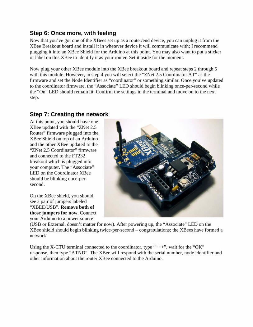
Step 7: Creating the network At this point, you should have one XBee updated with the “ZNet 2.5 Router” firmware plugged into the XBee Shield on top of an Arduino and the other XBee updated to the “ZNet 2.5 Coordinator” firmware and connected to the FT232 breakout which is plugged into your computer. The “Associate” LED on the Coordinator XBee should be blinking once-per-second. On the XBee shield, you should see a pair of jumpers labeled “XBEE/USB”. Remove both of those jumpers for now. Connect your Arduino to a power source (USB or External, doesn’t matter for now). After powering up, the “Associate” LED on the XBee shield should begin blinking twice-per-second – congratulations; the XBees have formed a network! Using the X-CTU terminal connected to the coordinator, type “+++”, wait for the “OK” response, then type “ATND”. The XBee will respond with the serial number, node identifier and other information about the router XBee connected to the Arduino.
Step 8: Sending Serial Data When using the ZNet 2.5 firmware, routers or end devices will communicate with the coordinator by default. This makes point to point communication really easy. All you need to do is send serial data to the XBee router connected to the Arduino and it will be received by the coordinator where you can read it into your computer. Connect the Arduino with the XBee Shield to your computer using a USB cable. The jumpers on the XBee shield should still be disconnected. Load the following sketch on to the Arduino. /* Serial Test code Sends "testing..." over the serial connection o nce per second while blinking the LED on pin 13. Used for test ing serial devices such as the XBee. Adapted from the SoftSerial Demonstration code */ #define ledPin 13 byte pinState = 0; void setup() { pinMode(ledPin, OUTPUT); Serial.begin(9600); } void loop() { Serial.println("testing..."); // toggle an LED just so you see the thing's aliv e. toggle(13); delay(1000); } void toggle(int pinNum) { // set the LED pin using the pinState variable: digitalWrite(pinNum, pinState); // if pinState = 0, set it to 1, and vice versa: pinState = !pinState; }
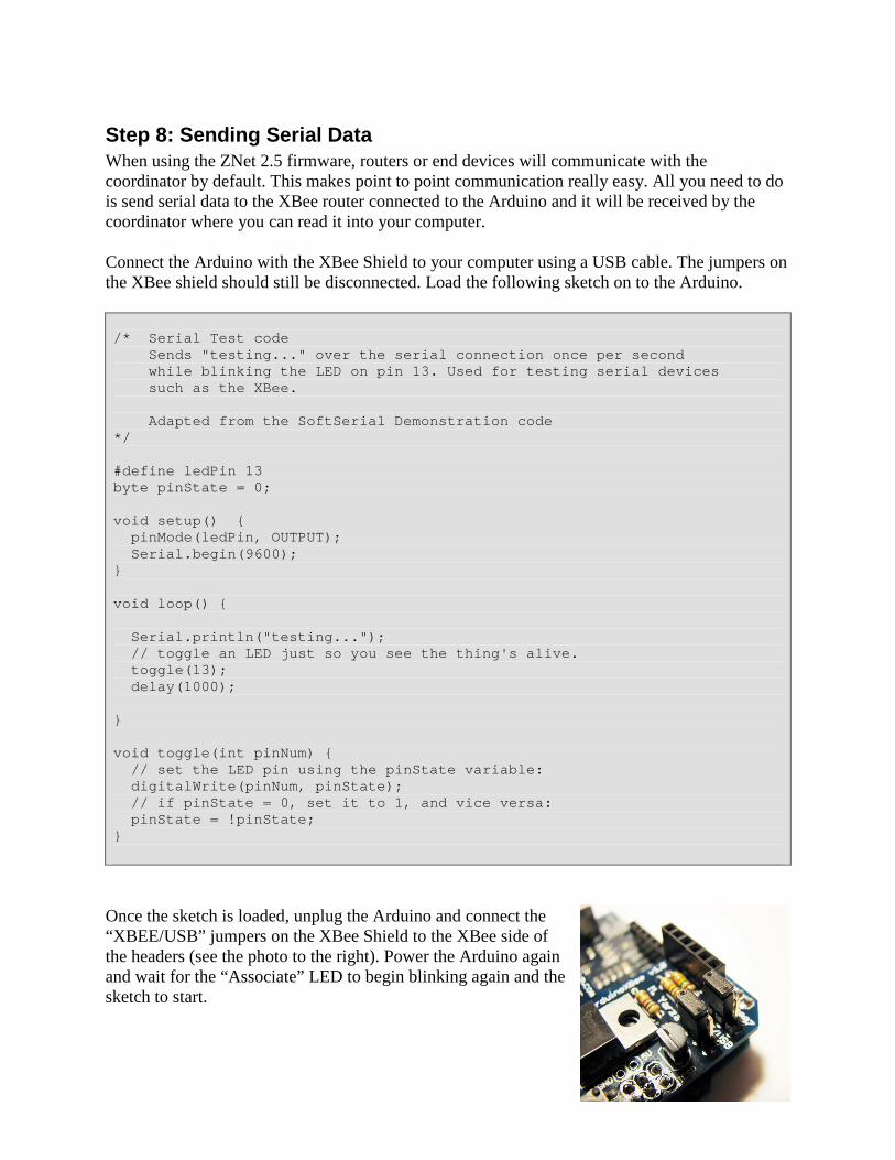
Once the sketch is loaded, unplug the Arduino and connect the “XBEE/USB” jumpers on the XBee Shield to the XBee side of the headers (see the photo to the right). Power the Arduino again and wait for the “Associate” LED to begin blinking again and the sketch to start.

With the coordinator XBee still connected to your computer via the FT232 Breakout, you should see “testing…” over and over in the “Terminal” tab of X-CTU. Hooray, wireless communication!
Final Thoughts If you’ve gone through all these steps, you should have a basic idea of how to use the XBee ZNet modules to communicate wirelessly between your Arduino and your computer. If that’s all you want to do with the XBees, then there’s not much more (if anything) you’ll need to configure to get your project working. If you will be using more than two XBee modules and you want two routers/end devices to talk to one-another, you’ll need to set the Destination Nodes for each module. You can easily do this by entering command mode (typing “+++”) and then sending “ATDNxxxxxx” where xxxxxx is the Node Identifier (NI) you’ve set-up for the Destination Node XBee such as “router2”. This essentially replaces the “ATMYxxxx” command that is commonly used with XBee Series 1 modules. For more information about using the XBee ZNet modules, I highly recommend the Knowledge Base articles and support forum on Digi’s site, www.digi.com – the folks at Digi seem to be pretty good about offering support. I would appreciate any feed back on this tutorial. Feel free to e-mail me at ‘caimaver at yahoo dot com’. - Cairn