Embed Size (px)
Citation preview

e.com
3500
7031
06
www.telemecaniqu
Magelis XBTGUser Manual 35007031 eng

2

Document Set
Document Set
At a Glance This manual describes the XBTG terminals series implementation.
35007031 11/2006 3

Document Set
4 35007031 11/2006

Table of Contents
Safety Information . . . . . . . . . . . . . . . . . . . . . . . . . . . . . . . . . . . .9
About the Book . . . . . . . . . . . . . . . . . . . . . . . . . . . . . . . . . . . . . .13
Part I XBTG Panels. . . . . . . . . . . . . . . . . . . . . . . . . . . . . . . . . . . 15At a glance . . . . . . . . . . . . . . . . . . . . . . . . . . . . . . . . . . . . . . . . . . . . . . . . . . . . . 15
Chapter 1 Overview . . . . . . . . . . . . . . . . . . . . . . . . . . . . . . . . . . . . . . . . . . .17At a glance . . . . . . . . . . . . . . . . . . . . . . . . . . . . . . . . . . . . . . . . . . . . . . . . . . . . . 17Series of XBTG Panels . . . . . . . . . . . . . . . . . . . . . . . . . . . . . . . . . . . . . . . . . . . . 18Package contents . . . . . . . . . . . . . . . . . . . . . . . . . . . . . . . . . . . . . . . . . . . . . . . . 19Series XBTG panels and standards . . . . . . . . . . . . . . . . . . . . . . . . . . . . . . . . . . 20CE marking notes . . . . . . . . . . . . . . . . . . . . . . . . . . . . . . . . . . . . . . . . . . . . . . . . 21
Chapter 2 XBTG Device Connectivity. . . . . . . . . . . . . . . . . . . . . . . . . . . . .23At a glance . . . . . . . . . . . . . . . . . . . . . . . . . . . . . . . . . . . . . . . . . . . . . . . . . . . . . 23System design. . . . . . . . . . . . . . . . . . . . . . . . . . . . . . . . . . . . . . . . . . . . . . . . . . . 24Accessories . . . . . . . . . . . . . . . . . . . . . . . . . . . . . . . . . . . . . . . . . . . . . . . . . . . . . 26
Chapter 3 Specifications . . . . . . . . . . . . . . . . . . . . . . . . . . . . . . . . . . . . . . .29At a glance . . . . . . . . . . . . . . . . . . . . . . . . . . . . . . . . . . . . . . . . . . . . . . . . . . . . . 29
3.1 General specifications. . . . . . . . . . . . . . . . . . . . . . . . . . . . . . . . . . . . . . . . . . . . . 31At a glance . . . . . . . . . . . . . . . . . . . . . . . . . . . . . . . . . . . . . . . . . . . . . . . . . . . . . 31Electrical specifications . . . . . . . . . . . . . . . . . . . . . . . . . . . . . . . . . . . . . . . . . . . . 32Environmental specifications. . . . . . . . . . . . . . . . . . . . . . . . . . . . . . . . . . . . . . . . 33Structural specifications . . . . . . . . . . . . . . . . . . . . . . . . . . . . . . . . . . . . . . . . . . . 34
3.2 Functional specifications . . . . . . . . . . . . . . . . . . . . . . . . . . . . . . . . . . . . . . . . . . . 35At a glance . . . . . . . . . . . . . . . . . . . . . . . . . . . . . . . . . . . . . . . . . . . . . . . . . . . . . 35Display. . . . . . . . . . . . . . . . . . . . . . . . . . . . . . . . . . . . . . . . . . . . . . . . . . . . . . . . . 36Memory and clock . . . . . . . . . . . . . . . . . . . . . . . . . . . . . . . . . . . . . . . . . . . . . . . . 38Interfaces. . . . . . . . . . . . . . . . . . . . . . . . . . . . . . . . . . . . . . . . . . . . . . . . . . . . . . . 39
3.3 Interface specifications . . . . . . . . . . . . . . . . . . . . . . . . . . . . . . . . . . . . . . . . . . . . 42At a glance . . . . . . . . . . . . . . . . . . . . . . . . . . . . . . . . . . . . . . . . . . . . . . . . . . . . . 42Specification serial interface COM1 . . . . . . . . . . . . . . . . . . . . . . . . . . . . . . . . . . 43Specification of serial interface COM2 . . . . . . . . . . . . . . . . . . . . . . . . . . . . . . . . 46
5

Other interfaces . . . . . . . . . . . . . . . . . . . . . . . . . . . . . . . . . . . . . . . . . . . . . . . . . . 473.4 Part numbers and functions. . . . . . . . . . . . . . . . . . . . . . . . . . . . . . . . . . . . . . . . . 48
At a glance. . . . . . . . . . . . . . . . . . . . . . . . . . . . . . . . . . . . . . . . . . . . . . . . . . . . . . 48Part numbers and functions. . . . . . . . . . . . . . . . . . . . . . . . . . . . . . . . . . . . . . . . . 49DIP Switches . . . . . . . . . . . . . . . . . . . . . . . . . . . . . . . . . . . . . . . . . . . . . . . . . . . . 53
3.5 Dimensions . . . . . . . . . . . . . . . . . . . . . . . . . . . . . . . . . . . . . . . . . . . . . . . . . . . . . 54At a glance. . . . . . . . . . . . . . . . . . . . . . . . . . . . . . . . . . . . . . . . . . . . . . . . . . . . . . 54XBTG2110 dimensions . . . . . . . . . . . . . . . . . . . . . . . . . . . . . . . . . . . . . . . . . . . . 55XBTG2120, XBTG2130, XBT-G2220, and XBTG2330 dimensions . . . . . . . . . . 56XBTG4320 and XBTG4330 dimensions . . . . . . . . . . . . . . . . . . . . . . . . . . . . . . . 57XBTG5230, XBTG 5330 and XBTG6330 dimensions . . . . . . . . . . . . . . . . . . . . . 58Panel cut dimensions. . . . . . . . . . . . . . . . . . . . . . . . . . . . . . . . . . . . . . . . . . . . . . 59Installation Fasteners. . . . . . . . . . . . . . . . . . . . . . . . . . . . . . . . . . . . . . . . . . . . . . 60
Chapter 4 Installation and wiring . . . . . . . . . . . . . . . . . . . . . . . . . . . . . . . . 61At a glance. . . . . . . . . . . . . . . . . . . . . . . . . . . . . . . . . . . . . . . . . . . . . . . . . . . . . . 61
4.1 Installation . . . . . . . . . . . . . . . . . . . . . . . . . . . . . . . . . . . . . . . . . . . . . . . . . . . . . . 63Installation procedures. . . . . . . . . . . . . . . . . . . . . . . . . . . . . . . . . . . . . . . . . . . . . 63
4.2 Wiring Precautions. . . . . . . . . . . . . . . . . . . . . . . . . . . . . . . . . . . . . . . . . . . . . . . . 65At a glance. . . . . . . . . . . . . . . . . . . . . . . . . . . . . . . . . . . . . . . . . . . . . . . . . . . . . . 65Connecting the Power Cord. . . . . . . . . . . . . . . . . . . . . . . . . . . . . . . . . . . . . . . . . 66Connecting the Power Supply . . . . . . . . . . . . . . . . . . . . . . . . . . . . . . . . . . . . . . . 68Grounding . . . . . . . . . . . . . . . . . . . . . . . . . . . . . . . . . . . . . . . . . . . . . . . . . . . . . . 69Input/Output Line placement . . . . . . . . . . . . . . . . . . . . . . . . . . . . . . . . . . . . . . . . 71
4.3 Tool Port Connector. . . . . . . . . . . . . . . . . . . . . . . . . . . . . . . . . . . . . . . . . . . . . . . 72At a glance. . . . . . . . . . . . . . . . . . . . . . . . . . . . . . . . . . . . . . . . . . . . . . . . . . . . . . 72Tool Port Connector. . . . . . . . . . . . . . . . . . . . . . . . . . . . . . . . . . . . . . . . . . . . . . . 73USB Data Transfer Cable (XBTZG925) - Installation . . . . . . . . . . . . . . . . . . . . . 74
4.4 Ethernet Cable Connector . . . . . . . . . . . . . . . . . . . . . . . . . . . . . . . . . . . . . . . . . . 77Ethernet Cable Connector . . . . . . . . . . . . . . . . . . . . . . . . . . . . . . . . . . . . . . . . . . 77
4.5 Printer Cable Connector . . . . . . . . . . . . . . . . . . . . . . . . . . . . . . . . . . . . . . . . . . . 78Printer cable connector . . . . . . . . . . . . . . . . . . . . . . . . . . . . . . . . . . . . . . . . . . . . 78
4.6 CF Card Installation and Removal . . . . . . . . . . . . . . . . . . . . . . . . . . . . . . . . . . . . 81CF Card Installation and Removal . . . . . . . . . . . . . . . . . . . . . . . . . . . . . . . . . . . . 81
4.7 Sound Output. . . . . . . . . . . . . . . . . . . . . . . . . . . . . . . . . . . . . . . . . . . . . . . . . . . . 84Sound Output. . . . . . . . . . . . . . . . . . . . . . . . . . . . . . . . . . . . . . . . . . . . . . . . . . . . 84
Part II Settings and debugging . . . . . . . . . . . . . . . . . . . . . . . . . .85At a Glance . . . . . . . . . . . . . . . . . . . . . . . . . . . . . . . . . . . . . . . . . . . . . . . . . . . . . 85
6

Chapter 5 Settings . . . . . . . . . . . . . . . . . . . . . . . . . . . . . . . . . . . . . . . . . . . .87At a Glance . . . . . . . . . . . . . . . . . . . . . . . . . . . . . . . . . . . . . . . . . . . . . . . . . . . . . 87
5.1 XBTG settings . . . . . . . . . . . . . . . . . . . . . . . . . . . . . . . . . . . . . . . . . . . . . . . . . . . 89At a Glance . . . . . . . . . . . . . . . . . . . . . . . . . . . . . . . . . . . . . . . . . . . . . . . . . . . . . 89Types of Settings. . . . . . . . . . . . . . . . . . . . . . . . . . . . . . . . . . . . . . . . . . . . . . . . . 90Offline settings. . . . . . . . . . . . . . . . . . . . . . . . . . . . . . . . . . . . . . . . . . . . . . . . . . . 91System settings . . . . . . . . . . . . . . . . . . . . . . . . . . . . . . . . . . . . . . . . . . . . . . . . . . 93
Chapter 6 Troubleshooting . . . . . . . . . . . . . . . . . . . . . . . . . . . . . . . . . . . . .97At a Glance . . . . . . . . . . . . . . . . . . . . . . . . . . . . . . . . . . . . . . . . . . . . . . . . . . . . . 97
6.1 Troubleshooting Checklists . . . . . . . . . . . . . . . . . . . . . . . . . . . . . . . . . . . . . . . . . 99Troubleshooting Checklists . . . . . . . . . . . . . . . . . . . . . . . . . . . . . . . . . . . . . . . . . 99
6.2 Self Test . . . . . . . . . . . . . . . . . . . . . . . . . . . . . . . . . . . . . . . . . . . . . . . . . . . . . . 101Self test item list . . . . . . . . . . . . . . . . . . . . . . . . . . . . . . . . . . . . . . . . . . . . . . . . 101
Chapter 7 Maintenance . . . . . . . . . . . . . . . . . . . . . . . . . . . . . . . . . . . . . . .105At a glance . . . . . . . . . . . . . . . . . . . . . . . . . . . . . . . . . . . . . . . . . . . . . . . . . . . . 105Regular Cleaning. . . . . . . . . . . . . . . . . . . . . . . . . . . . . . . . . . . . . . . . . . . . . . . . 106Periodic check points . . . . . . . . . . . . . . . . . . . . . . . . . . . . . . . . . . . . . . . . . . . . 108Replacing the backlight . . . . . . . . . . . . . . . . . . . . . . . . . . . . . . . . . . . . . . . . . . . 109
Index . . . . . . . . . . . . . . . . . . . . . . . . . . . . . . . . . . . . . . . . . . . . . 111
7

8

§
Safety InformationGeneral Safety Precautions
NOTICE Read these instructions carefully, and look at the equipment to become familiar with the device before trying to install, operate, or maintain it. The following special messages may appear throughout this documentation or on the equipment to warn of potential hazards or to call attention to information that clarifies or simplifies a procedure.
The addition of this symbol to a Danger or Warning safety label indicatesthat an electrical hazard exists, which will result in personal injury if theinstructions are not followed.
This is the safety alert symbol. It is used to alert you to potential personalinjury hazards. Obey all safety messages that follow this symbol to avoidpossible injury or death.
DANGER indicates an imminently hazardous situation, which, if not avoided, will result in death or serious injury.
DANGER
WARNING indicates a potentially hazardous situation, which, if not avoided, can result in death, serious injury, or equipment damage.
WARNING
CAUTION indicates a potentially hazardous situation, which, if not avoided, can result in injury or equipment damage.
CAUTION
35007031 11/2006 9
Safety Information
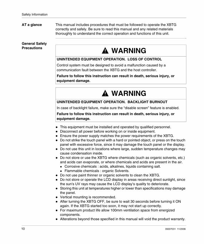
AT a glance This manual includes procedures that must be followed to operate the XBTG correctly and safely. Be sure to read this manual and any related materials thoroughly to understand the correct operation and functions of this unit.
General Safety Precautions
This equipment must be installed and operated by qualified personnel.Disconnect all power before working on or inside equipment.Ensure the power supply matches the power requirements of the XBTG.Do not strike the touch panel with a hard or pointed object, or press on the touch panel with excessive force, since it may damage the touch panel or the display. Do not use this unit in locations where large, sudden temperature changes may cause condensation inside.Do not store or use the XBTG where chemicals (such as organic solvents, etc.) and acids can evaporate, or where chemicals and acids are present in the air.
Corrosive chemicals : acids, alkalines, liquids containing salt. Flammable chemicals : organic Solvents.
Do not use paint thinner or organic solvents to clean the XBTG. Do not store or operate the LCD display in areas receiving direct sunlight, since the sun's UV rays may cause the LCD display’s quality to deteriorate. Storing this unit at temperatures higher or lower than specifications may damage the panel. Vertical mounting is recommended.After turning the XBTG OFF, be sure to wait 30 seconds before turning it ON again. If the XBTG started too soon, it may not start up correctly. For maximum product life allow 100mm ventilation space from energized components.Alterations beyond those specified in this manual will void the product warranty.
WARNINGUNINTENDED EQUIPMENT OPERATION. LOSS OF CONTROL
Control system must be designed to avoid a malfunction caused by a communication fault between the XBTG and the host controller.
Failure to follow this instruction can result in death, serious injury, or equipment damage.
WARNINGUNINTENDED EQUIPMENT OPERATION. BACKLIGHT BURNOUT
In case of backlight failure, make sure the “disable screen” feature is enabled.
Failure to follow this instruction can result in death, serious injury, or equipment damage.
10 35007031 11/2006

Safety Information
When using scripts to display screens, ensure that they are not displayed in a Popup window. Failure to follow this instruction may cause the image to be clipped within the Popup window. The vibrate mode is not available on the XBTG; this mode is reserved for a future use.While in the modification mode with the virtual keyboard displayed, any change of focus (outside of the virtual keyboard window) will close the virtual keyboard and input data will be lost.During the design phase of your project, ensure that only one protocol is configured to a communications port. Multiple protocols can not be assigned to a single port.If sound distortion is present, check the file format of the sound (*.wav) file used and ensure that it is formatted for 16 bits, 11 kHz.
Concerning the USB Data Transfer Cable XBTZG925
To prevent damage to the USB data transfer cable:
Do not use or store this cable at very high temperatures, or in direct sunlight.Do not use or store this cable in excessively dusty or dirty environments.Do not use or store this cable in a environment where it may be exposed to chemical vapors or fumes.Do not allow water to enter the connector. Also, do not touch the connector if your hands are wet. This may cause an electrical shock.Do not connect or disconnect the USB data transfer cable during data transfer. Doing so may cause a data communication error.
WARNINGUNINTENDED EQUIPMENT OPERATION.
Care must be taken during design not to allow Pop up windows to overlay virtual keyboard.
Failure to follow this instruction can result in death, serious injury, or equipment damage.
35007031 11/2006 11

Safety Information
12 35007031 11/2006

About the Book
At a Glance
Document Scope This manual describes the XBTG terminals series implementation.
Validity Note Contents
User Comments We welcome your comments about this document. You can reach us by e-mail at [email protected]
35007031 11/2006 13

About the Book
14 35007031 11/2006

35007031 11/2006
I
XBTG PanelsAt a glance
Subject of this part
This part presents XBTG Panels.
What's in this Part?
This part contains the following chapters:
Chapter Chapter Name Page
1 Overview 17
2 XBTG Device Connectivity 23
3 Specifications 29
4 Installation and wiring 61
15

XBTG Panels
16 35007031 11/2006

35007031 11/2006
1
OverviewAt a glance
Subject of this Chapter
This chapter presents series of XBTG Panels and devices connectable to the XBTG.
What's in this Chapter?
This chapter contains the following topics:
Topic Page
Series of XBTG Panels 18
Package contents 19
Series XBTG panels and standards 20
CE marking notes 21
17

Overview
Series of XBTG Panels
Overview This manuals presents the XBTG series of Human Machine Interface products. These products are graphical touchscreens and have an operating voltage of 24 Volts DC. The products offered in this series have various features and benefits listed below:
screen size,resolution of the screen,technology and color of the screen,communication.
Part Number The following table introduce the different XBTG Products:
STN and TFT STN: Scan Twisted Neumatic also known as passive matrix.
TFT: Thin Film Transistors also known as active matrix.
Part number Screen size Resolution Pixels Mono/Color Screen technology Serial link Ethernet
XBTG2110 5.7" QVGA320x240
Blue mode STN 1 No
XBTG2120 5.7" QVGA320x240
Monochrome STN 1 No
XBTG2130 5.7" QVGA320x240
Monochrome STN 2 Yes
XBTG2220 5.7" QVGA320x240
Color STN 1 No
XBTG2330 5.7" QVGA320x240
Color TFT 2 Yes
XBTG4320 7.4" VGA640x480
Color TFT 1 No
XBTG4330 7.4" VGA640x480
Color TFT 2 Yes
XBTG5230 10.4" VGA640x480
Color STN 2 Yes
XBTG5330 10.4" VGA640x480
Color TFT 2 Yes
XBTG6330 12.1" SVGA800x600
Color TFT 2 Yes
18 35007031 11/2006

Overview
Package contents
At a glance The following items are included in the XBTG's package. Before using the XBTG, please make sure that all items listed here are present:
XBTG Unit,PLC cable adaptor XBTZG999, plugged on the serial interface (HOST -I/F 25 pin),Installation Guide,Installation Fasteners (4),Installation Gasket.
Options XBTG optional items include cables, adapters, screen editor software and other items. For more information about these optional items, please refer to individual XBTG catalogues.
Revisions You can identify the revision from the product label sticker pasted on the XBTG unit. Revision is consisted of letters and numbes at the location marked with "*" sign.
The following diagram show a example of unit revision. In this example the revision is C,1,2:
0123456789 0123456789 0123456789
C
XBTG2110
REV AB*DEFGHIJKLMNOPQRSTUVWXYZ**345
24V0302
0.84A FID:xxxx
Made in JapanSN: xxxxxxxxxxx
LRxxxxxxLISTED INDUSTRIAL CONTROL EQUIPMENTFOR HAZARDOUS LOCATIONS 3R23Class1 Division 2 Group A,B,C and DTemperature Code-T4A
35007031 11/2006 19

Overview
Series XBTG panels and standards
At a glance The XBTG are UL/C-UL listed and CSA products.
These units are conformed to the following standards:
UL 508 for Industrial Control Equipement,UL 1604 Electrical Equipment for Use in Hazardous Location for use in Class I and Class II Division 2 and Class III Hazardous Locations,UL 60950 Standard for Safety of Information Technology EquipmentCAN/CSA-C22.2 No.142 and No.213-M1987 Industrial Control Equipment- Miscellaneous Apparatus - For Hazardous Locations.
UL1604 Conditions of Acceptability and Handling Cautions:
Power, input and output (I/O) wiring must be in accordance with Class I, Division 2 wiring methods - Article 501- 4(b) of the National Electrical Code, NFPA 70 or as specified in section 18-152 of the Canadian Electrical Code for installations within Canada and in accordance with the authority have jurisdiction.Suitable for use in Class I, Division 2, Groups A, B, C and D Hazardous Locations or non- Hazardous Locations only.Confirm that the power supply has been turned OFF before disconnecting equipment, or confirm that the location is not subject to the risk of explosion.WARNING: Explosion hazard - substitution of components may impair suitability for Class I, Division 2.WARNING: Explosion hazard - when in hazardous locations, turn power OFF before replacing or wiring modules.WARNING: Explosion hazard - do not disconnect equipment unless power has been switched OFF or the area is known to be non-hazardous.
20 35007031 11/2006

Overview
CE marking notes
At a glance The XBTG units are CE marked products. They follow the standards bellow:
Environnement Standards
Compliance with standards IEC 61131-2, IEC61000-6-2,CISPR11(Class A) UL 508, CSA C22.2 n°142 & n°213
Product certification CE, UL/cUL, CSA, Class 1 Div 2 T4A or T5* (UL & CSA)* : only for the references XBTG4•••
Operating temperature 0°C + 50°C (32°F 122°F)
Storage temperature -20 °C + 60°C (-4°F 140°F)
Protection (front panel) IP 65 - (IEC 60529)UL Type 4, 4X Indoor use
Protection (rear panel) IP 20 - (IEC 60529)
ESD withstand IEC 61000 - 4 - 2level 3
Electromagnetic interference
IEC 61000 - 4 - 310 V / m
Electrical interference IEC 61000- 4 - 4level 3
High Energy Surges IEC 61000 - 4 - 50.5KV (Differential Mode on power supply)1KV (common mode on power supply)
Shocks IEC 60068 - 2 - 271/2 sinusoidal pulse for 11ms, 15 g on 3 axes
Vibration IEC 60068 - 2 - 6 0.075mm 10 Hz to 57 Hz1 g. 57 Hz to 150 Hz
Pollution Degree Pollution Degree 2
35007031 11/2006 21

Overview
22 35007031 11/2006

35007031 11/2006
2
XBTG Device ConnectivityAt a glance
Subject of this chapter
This chapter presents for each XBTG unit the devices connectable to it.
What's in this Chapter?
This chapter contains the following topics:
Topic Page
System design 24
Accessories 26
23
XBTG Device Connectivity
System design
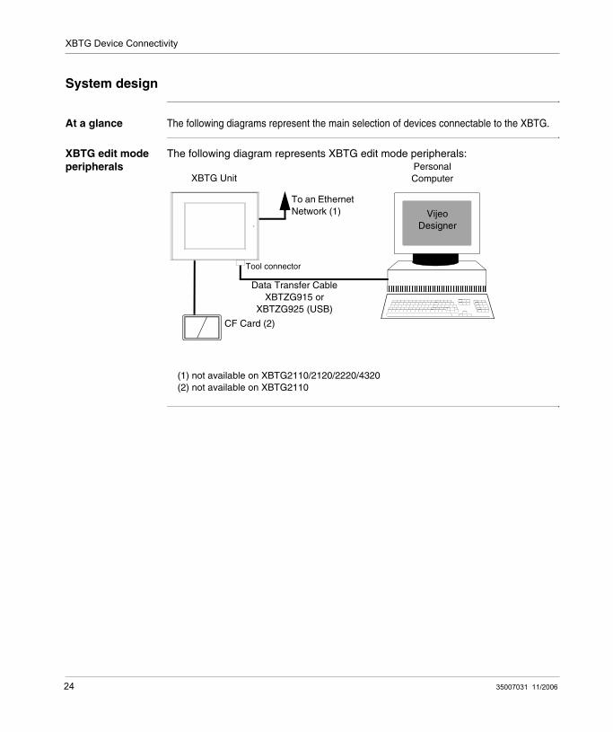
At a glance The following diagrams represent the main selection of devices connectable to the XBTG.
XBTG edit mode peripherals
The following diagram represents XBTG edit mode peripherals:
Data Transfer Cable XBTZG915 or
XBTZG925 (USB)
XBTG UnitPersonal Computer
Vijeo Designer
CF Card (2)
To an Ethernet Network (1)
(1) not available on XBTG2110/2120/2220/4320(2) not available on XBTG2110
Tool connector
24 35007031 11/2006

XBTG Device Connectivity
XBTG run mode peripherals
The following diagram represents XBTG run mode peripherals:
XBTZG999cable convertor
XBTG Unit
PLCCF Card (2)
To an Ethernet Network (7)
(1) not available on XBTG2110/2120/2220(2) not available on XBTG2110(3) not available on XBTG2110/2120/2130/2220/2330/4320(4) not available on XBTG2110/2120/2220/4320 when COM1 is used(5) for parallel printer(6) for serial printer(7) not available on XBTG2110/2120/2220/4320
Speaker (3)
XBTZ••• cable
Bar Code Reader (4)
XBTZG946 (1)(5)XBTZG936 (6)
35007031 11/2006 25

XBTG Device Connectivity
Accessories
Part number The following table presents all accessories used with XBTG:
Part number Product name Description XBTG series
XBTZG915 Cable Connects the XBTG to a personal computer (COM1, COM2,). Downloads user created program.
For all
XBTZG925 USB Cable Connects the XBTG to a personal computer (USB port). Downloads user created program.
For all
XBTZG936 Serial Cable To connect the XBTG to a printer thought serial port
For all
XBTZG946 Printer cable To connect the XBTG to a printer through parallel port.
For all except XBTG2110/2120/2220
XBTZG999 XBTZ cable convertor
Adapt the XBTZ cable connector to XBTG COM1 port.
For all
XBTZG968XBTZG9680XBTZG9681
XBTZ cable Cable to connect equipment to XBTG with XBTZ cable convector.
For all
XBTZG9710XBTZG9711
XBTZ cable Cable to connect equipment to XBTG with XBTZ cable convector.
For all
XBTZG918 XBTZ cable Cable to connect equipment to XBTG with XBTZ cable convector.
For all
XBTZG908 XBTZ cable Cable to connect equipment to XBTG with XBTZ cable convector and TSX SCA 62.
For all
TSX PCX 1031 XBTZ cable Cable to connect equipment to XBTG (COM2).
For all
XBTZGM16 CF card (16MB) XBTG series CF card (16MB). For all except XBTG2110
XBTZGM32 CF card (32MB) XBTG series CF card (32MB). For all except XBTG2110
XBTZGM64 CF card (64MB) XBTG series CF card (64MB). For all except XBTG2110
XBTZGM128 CF card (128MB) XBTG series CF card (128MB). For all except XBTG2110
XBTZGM256 CF card (256MB) XBTG series CF card (256MB). For all except XBTG2110
MPCYN00CFE00N CF card (512MB) XBTG series CF card (512MB). For all except XBTG2110
XBTZGADT CF card adaptor CF card adapter for the PCMCIA slot. For all except XBTG2110
26 35007031 11/2006

XBTG Device Connectivity
XBTZG12 Backlight Replacement backlight. For XBTG2120/2130/2220
XBTZG13 For XBTG5230
XBTZG14 For XBTG4320/4330
XBTZG15 For XBTG5330
XBTZG16 For XBTG6330(REV AB*DEFGHIJKLMNOPQRSTUVWXYZ12345)
XBTZG46 For XBTG6330(REV AB*DEFGHIJKLMNOPQRSTUVWXYZ*2345)
XBTZGSET Installation fastener Fasteners to attach the XBTG a panel.
For all
XBTZG21 Installation gasket. Provides a moisture resistant seal when installing the XBTG. Same as the seal included the XBTG’s original equipment package.
For XBTG2110
XBTZG22 For XBTG2120/2130/2230/2330
XBTZG24 For XBTG4320/4330
XBTZG26 For XBTG5230/5330/6330
XBTZG31 Screen protection sheet.
Disposable, dirt-resistant sheet for the XBTG’s screen. The XBTG’s touch panel can be operated with this cover sheet attached.
For XBTG2110
XBTZG32 For XBTG2130/2330
XBTZG34 For XBTG4320/4330
XBTZG36 For XBTG5230/5330/6330
XBTZGCOV Connectors cover. Attaches to XBTG rear face connectors.
For XBTG2130/2330/4320/4330/5230/5330/6330
XBTZGMBP Connection module for ModBus Plus networks
Allows connection to a ModBus Plus network.
For all except XBTG2110
Part number Product name Description XBTG series
35007031 11/2006 27

XBTG Device Connectivity
28 35007031 11/2006

35007031 11/2006
3
SpecificationsAt a glance
Subject of this chapter
This chapter presents the different XBTG specifications (general, functional, interface).
What's in this Chapter?
This chapter contains the following sections:
Section Topic Page
3.1 General specifications 31
3.2 Functional specifications 35
3.3 Interface specifications 42
3.4 Part numbers and functions 48
3.5 Dimensions 54
29

Specifications
30 35007031 11/2006

Specifications
3.1 General specifications
At a glance
Subject of this section
This section presents general XBTG specifications (electrical, environmental and structural).
What's in this Section?
This section contains the following topics:
Topic Page
Electrical specifications 32
Environmental specifications 33
Structural specifications 34
35007031 11/2006 31
Specifications
Electrical specifications
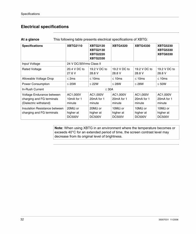
At a glance This following table presents electrical specifications of XBTG:
Specifications XBTG2110 XBTG2120XBTG2130XBTG2220XBTG2330
XBTG4320 XBTG4330 XBTG5230XBTG5330XBTG6330
Input Voltage 24 V DC/30Vrms Class II
Rated Voltage 20.4 V DC to 27.6 V
19.2 V DC to 28.8 V
19.2 V DC to 28.8 V
19.2 V DC to 28.8 V
19.2 V DC to 28.8 V
Allowable Voltage Drop ≤ 2ms ≤ 10ms ≤ 10ms ≤ 10ms ≤ 10ms
Power Consumption ≤ 20W ≤ 22W ≤ 28W ≤ 28W ≤ 50W
In-Rush Current ≤ 30A
Voltage Endurance between charging and FG terminals (Dielectric withstand)
AC1,000V 10mA for 1 minute
AC1,000V 20mA for 1 minute
AC1,000V 20mA for 1 minute
AC1,000V 20mA for 1 minute
AC1,000V 20mA for 1 minute
Insulation Resistance between charging and FG terminals
20MΩ or higher at DC500V
20MΩ or higher at DC500V
10MΩ or higher at DC500V
10MΩ or higher at DC500V
10MΩ or higher at DC500V
Note: When using XBTG in an environment where the temperature becomes or exceeds 40°C for an extended period of time, the screen contrast level may decrease from its original level of brightness.
32 35007031 11/2006

Specifications
Environmental specifications
At a glance This following table presents environmental specifications of XBTG:
Specifications XBTG2110 XBTG2120XBTG2130XBTG2220XBTG2330
XBTG4320 XBTG4330 XBTG5230XBTG5330XBTG6330
Ambient operating temperature
0°C to +50°C (32°F 122°F) (1)
Storage temperature -20°C to +60°C (-4°F 140°F)
Ambient humidity 20%RH to 85%RH
10%RH to 90%RH
10%RH to 90%RH
10%RH to 90%RH
10%RH to 90%RH
Non condensing, wet bulb temperature : ≤ 39°C
Atmospheric endurance 800 to 1114hPa (≤ 2000meters) (23.62 to 32.9 inHg)
Air purity level≤ 0.1mg/ non-conductive levels
Atmosphere Free of corrosive gasses
Vibration resistance Non-continuous vibration: 0.075mm 10Hz to 50Hz, 9.8m/s 57Hz to 150HzContinuous vibration: 0.035mm 10Hz to 50Hz, 4.9m/s 57Hz to 150Hz x,y,z directions for 10 times (80min)
Noise immunity(via noise simulator)
Noise voltage: 1000Vp-pPulse duration: 1µ secRise time:1nsec
Electrostatic discharge immunity
Complies with IEC 61000-4-2 level 3
(1): The LCD displays of XBTG2130/2120/2220/6330 may occasionally blur when they are used for hours at over 40°C ambient operating temperature. After the temperature returns to normal, the normal display will be restored. The XBTG’s operation will not be affected even though the display is blurred.
m3
35007031 11/2006 33

Specifications
Structural specifications
At a glance This following table presents structural specifications of XBTG:
Specifications XBTG2110 XBTG2120XBTG2130XBTG2220XBTG2330
XBTG4320 XBTG4330 XBTG5230XBTG5330XBTG6330
Grounding ≤100Ω or your country’s applicable standard
Ratings (front face of installed unit)
Equivalent to IP65 (JEM 1030) (1) NEMA#250 Type 4X/12
Weight (main unit only)
≤1.1kg (2.4lb) ≤1.2kg (2.6lb) ≤1.7kg (5.5lb) ≤1.7kg (5.5lb) ≤3.5kg (7.7lb)
Cooling method Natural air circulation
External dimensionsWxHxD mm
207 x 157 x 58 171 x 138 x 60 215 x 170 x 60 215 x 170 x 60 317 x 243 x 58
External dimensionsWxHxD in.
8.17 x 6.18 x 2.28 6.73 x 5.43 x 2.36 8.46 x 6.69 x 2.36 8.46 x 6.69 x 2.36 12.48 x 9.57 x 2.28
Note: (1) the front face of the XBTG unit, installed in a solid panel, has been tested using conditions equivalent to the standards shown in the specification. Even though the XBTG unit’s level of resistance is equivalent to these standards, oils that should have no effect on the XBTG can possibly harm the unit. This can occur in areas where either vaporized oils are present, or where low viscosity cutting oils are allowed to adhere to the unit for long periods of time. If the XBTG’s front face protection sheet becomes peeled off, these conditions can lead to the ingress of oil into the XBTG and separate protection measures are suggested. Also, if non-approved oils are present, it may cause deformation or corrosion of the front panel’s plastic cover. Therefore, prior to installing the XBTG be sure to confirm the type of conditions that will be present in the XBTG’s operating environment. If the installation gasket is used for a long period of time, or if the unit and its gasket are removed from the panel, the original level of the protection cannot be guaranteed. To maintain the original protection level, you need to replace the installation gasket regularly.
34 35007031 11/2006

Specifications
3.2 Functional specifications
At a glance
Subject of this section
This section presents functional specifications (display, memory, and interfaces).
What's in this Section?
This section contains the following topics:
Topic Page
Display 36
Memory and clock 38
Interfaces 39
35007031 11/2006 35

Specifications
Display
At a glance The following table lists display specifications of XBTG units. The XBTG unit are grouped together in tables according to:
STN screen technology,TFT screen technology.
STN Display XBTG unit
This following table lists the display specification of XBTG unit with STN screen technology.
Specifications XBT-G2110 XBT-G2120XBT-G2130
XBT-G2220 XBT-G5230
Type Monochrome LCD Color LCD
Colors Blue mode B&W 64 colors 64 colors, 3-speed blink
Resolution (pixels)
320x240 640x480
Display area
WxH (mm) 115.2 x 86.4 211.2 x 158.4
WxH (in.) 4.54 x 3.40 8.34 x 6.24
Backlight CCFL (25,000 hrs at 25°C and 24hr. operation)
CFL (50,000 hrs at 25°C and 24hr. operation)
Contrast Control 4 levels of adjustment available via touch panel
Brightness adjust Set to maximum
Language fonts ASCII: (Code page 850) Alphanumeric (incl. Eur. characters) Chinese: (GB2321-80 codes) simplified Chinese fontsJapanese: ANK 158, Kanji : 6962 (JIS Standards 1 & 2) Korean: (KSC5601 - 1992 codes) Hangul fonts Taiwanese: (Big 5 codes) traditional Chinese fonts
Text
8x8 dots 40 char. per row, 30 rows 80 char. per row, 60 rows
8x16 dots 40 char. per row, 15 rows 80 char. per row, 30 rows
16x16 dots 20 char. per row, 15 rows 40 char. per row, 30 rows
32x32 dots 10 char. per row, 7 rows 20 char. per row, 15 rows
Font sizes Both height and width can be multiplied 1, 2, 4, or 8 times
Text sizes 8x8, 8x16, 16x16, and 32x32 dot fonts
Touch panel 16x12 keys/screen (1 or 2 point touch) 32x24 keys/screen (1 or 2 point touch)
36 35007031 11/2006

Specifications
TFT Display XBT-G unit
This following table lists the display specification of XBTG unit with TFT screen technology.
Specifications XBT-G2330 XBT-G4320XBT-G4330
XBT-G5330 XBT-G6330
Type Color LCD
Colors 256 colors, no blink 64 colors, 3-speed blink (1)
256 colors, no blink (1) 64 colors, 3-speed blink
Resolution (pixels) 320x240 640x480 800x600
Display area
WxH (mm) 115.2 x 86.4 149.8 x 112.3 211.2 x 158.4 246 x 184.5
WxH (in.) 4.54 x 3.40 5.90 x 4.42 8.34 x 6.24 9.69 x 7.26
Backlight (Service life) CFL (50,000 hrs at 25°C and 24hr. operation)
Contrast Control -
Brightness adjust 4 levels of adjustment available via touch panel
Languages fonts ASCII: (Code page 850) Alphanumeric (incl. Eur. characters) Chinese: (GB2321-80 codes) simplified Chinese fontsJapanese: ANK 158, Kanji : 6962 (JIS Standards 1 & 2) Korean: (KSC5601 - 1992 codes) Hangul fonts Taiwanese: (Big 5 codes) traditional Chinese fonts
Text
8x8 dots 40 char. per row, 30 rows 80 char. per row, 60 rows 100 char. per row, 75 rows
8x16 dots 40 char. per row, 15 rows 80 char. per row, 30 rows 100 char. per row, 37 rows
16x16 dots 20 char. per row, 15 rows 40 char. per row, 30 rows 50 char. per row, 37 rows
32x32 dots 10 char. per row, 7 rows 20 char. per row, 15 rows 25 char. per row, 18 rows
Font sizes Both height and width can be multiplied 1, 2, 4, or 8 times
Text sizes 8x8, 8x16, 16x16, and 32x32 dot fonts
Touch panel 16x12 keys/screen(1 or 2 point touch)
32x24 keys/screen(1 or 2 point touch)
40x30 keys/screen(1 or 2 point touch)
Legend
(1) Color swiching is done via software. Changing the "Colors" setting to "256 colors" will disable the blink feature on all of your project’s screens. If you wish to use the blink feature, select "64 colors"
35007031 11/2006 37

Specifications
Memory and clock
Memory The following table list the specifications memory of each XBTG unit.
Clock The internal clock accuracy of all XBTG units is +/- 65 seconds/month at ambient temperature.
The XBTG’s internal clock has a slight error. At normal operating temperatures and conditions, with the XBTG operating from its lithium battery, the degree of error is 65 seconds per month. Variations in operating conditions and battery life can cause this error to vary from -380 to +90 seconds per month. For systems where this degree of error will be a problem, the user should be sure to monitor this error and make adjustments when required.
Memory XBTG2110 XBTG2120XBTG2220
XBTG2130XBTG2330
XBTG4320 XBTG4330XBTG5230XBTG5330XBTG6330
ApplicationFlash EPROM
4Mb 4Mb 6Mb 6Mb 8Mb
Data backupSRAMuses a lithium battery (1)
128Kb 128Kb 512Kb 128Kb 512Kb
Legend:
(1) : a lithium battery’s lifetime is:10 years when the battery’s ambient temperature is under 40°C 4.1 years when the battery’s ambient temperature is under 50°C1.5 years when the battery’s ambient temperature is under 60°C
When used for backup:Approximately 60 days, with a fully charged batteryApproximately 6 days, with a half-charged battery
38 35007031 11/2006

Specifications
Interfaces
Serial interface and Tool Port connector
The Serial interface and Tool Port connector are available for all XBTG units.
The following table list the specifications of Serial interface and Tool Port connector.
Interface Description
Serial interface COM1 SUB-D 25
Asynchronous Transmission RS232C/RS485
Data length 7 or 8 bits
Stop bit 1 or 2 bits
Parity None, Odd or Even
Data transmission 2400bps to 115200 bps
Tool Port connector Mini Din Asynchronous TTL level non procedural command I/FUsed for transferring data user program from Vijeo-Designer to the XBTG.
35007031 11/2006 39

Specifications
Serial interface COM2 and Ethernet interface
The Serial interface COM2 and Ethernet interface are available for XBTG unit:
XBTG2130,XBTG2330,XBTG4330,XBTG5230,XBTG5330,XBTG6330.
The following table list the specifications of Serial interface COM2 and Ethernet interface.
Compact Flash memory Card interface
All XBTG units except XBTG2110 have one slot for Compact Flash memory Card interface.
Interface Description
Serial interface COM2 SUB-D 9
Asynchronous Transmission RS232C
Data length 7 or 8 bits
Stop bit 1 or 2 bits
Parity None, Odd or Even
Data transmission 2400bps to 115200 bps
Ethernet RJ 45 IEEE802.3, 10BaseT
40 35007031 11/2006

Specifications
Sound Output The Sound Output is available for XBTG unit:
XBTG4330,XBTG5230,XBTG5330,XBTG6330.
The following table list the specifications of Sound Output.
Interface Description
Sound Ouput
External Speaker Connection Terminal Block
Sound channel 1 mono channel
Speaker Output 70mW (Rated Load: 8W, Frequency: 1kHz)
Sound Line out output 2.7Vp-p (Rated Load:10kohm)
Wire Gauge AWG28 to AWG16
35007031 11/2006 41

Specifications
3.3 Interface specifications
At a glance
Subject of this section
This section presents interface specifications of XBTG units (Serial interface COM1, COM2).
What's in this Section?
This section contains the following topics:
Topic Page
Specification serial interface COM1 43
Specification of serial interface COM2 46
Other interfaces 47
42 35007031 11/2006

Specifications
Specification serial interface COM1
At a glance This interface that is used to connect the XBTG to the Remote Equipment, via an RS-232C or RS-485 cable. All XBTG units are equiped with this interface. The connector used is a socket-type connector.
The figure following presents the connector:
The following table presents the description of each pin’s serial interface.
25 1413 1
Pin Signal name Comm Descriptions Meaning for XBTG21101 FG Frame Ground Frame Ground
2 SD Send Data (RS-232C) Send Data (RS-232C)
3 RD Receive Data (RS-232C) Receive Data (RS-232C)
4 RS Request to Send (RS-232C) Request to Send (RS-232C)
5 CS Clear to Send (RS-232C) Clear to Send (RS-232C)
6 DR or NC Data Set Ready (RS-232C) No Connection (Reserved)
7 SG Signal Ground Signal Ground
8 CD Carrier Detect (RS-232C) Carrier Detect (RS-232C)
9 TRMX Termination (RS-485/RS-422) Termination (RS-485/RS-422)
10 RDA Receive Data A (RS-485/RS-422) Receive Data A (RS-485/RS-422)
11 SDA Send Data A (RS-485/RS-422) Send Data A (RS-485/RS-422)
12 NC No Connection(Reserved) No Connection (Reserved)
13 NC No Connection(Reserved) No Connection (Reserved)
14 VCC 5V 5% Output 0.25A 5V 5% Output 0.25A
15 SDB Send Data B (RS-485/RS-422) Send Data B (RS-485)
16 RDB Receive Data B (RS-485/RS-422) Receive Data B (RS-485/RS-422)
17 RI or NC Ring Indicate (RS-232C) No Connection (Reserved)
18 CSB Clear to Send B (RS-485/RS-422) Clear to Send B (RS-485/RS-422)
19 ERB Enable Receive B (RS-485/RS-422) Enable Receive B (RS-485/RS-422)
20 ER Enable Receive (RS-232C) Enable Receive (RS-232C)
21 CSA Clear to Send A (RS-485/RS-422) Clear to Send A (RS-485/RS-422)
22 ERA Enable Receive A (RS-485/RS-422) Enable Receive A (RS-485/RS-422)
23 NC or BUZZ GND No Connection(Reserved) External Buzzer Ground
24 NC No Connection(Reserved) No Connection(Reserved)
25 NC or BUZZ OUT No Connection(Reserved) External Buzzer Output
35007031 11/2006 43

Specifications
XBTZ-G999 cable adaptator
This cable adaptator is connected between XBTG unit (serial interface) and XBTZ••• cable.
The following figure presents XBTZ-G999’s connections.
Note: This XBTG unit’s serial port is not isolated. When the Remote Equipment unit is also not isolated, and to reduce the risk of damaging the RS-485 circuit, be sure to connect the #7 SG (Signal Ground) terminal.Pin #14 (VCC) DC 5V Output is not protected. To prevent damage or unit malfunction, use only the designated level of current.Be sure to connect the XBTG's SG/GND (Signal Ground) terminal to the other (host) unit's Signal Ground terminal.When connecting an external device to the XBTG with the SG terminal, ensure that no short-circuit loop is created when you setup the system.
DSUB 25 (Pin Type) DSUB 25 (Socket)
FG1SD2RD3RS4
RS232C OI
CS5DR6SG7CD8TRMX9RDASDA11NCNC
RS422
VCCSDBRDBRICSBERBER20CSAERA
RS485/422
NC
FGTXCRXCABA’0V isoCOM(0V)
REGCONFB0B1B2B3B’B4
0V iso
PAR
1213141516171819
2122232425
10
NCNC
RS232CRS232CRS232CRS232C
RS232C
RS422
RS422
RS485/422RS232CRS485/422RS485/422RS232CRS485/422RS485/422
OII
IIIO
OII
OI
OIO
123456789
11
20
1213141516171819
2122232425
10
44 35007031 11/2006

Specifications
Creating own cable
When creating a cable, please be aware of the following (see figure above):
For RS-485 Connectors:The following pairs of pin no.s must be connected (shorted).#18 (CSB) <-> #19 (ERB)#21 (CSA) <-> #22 (ERA)Connecting the #9 (TRMX) and #10 (RDA) wires, adds a termination resistance of 100 Ohm between RDA and RDB .
For RS-232C Connectors:Do not connect #9 (TRMX), #10 (RDA), #11 (SDA), #15 (SDB), #16 (RDB), #18 (CSB), #19 (ERB), #21 (CSA), and #22 (ERA).The #1 (FG) terminal should only be connected if it is required by the device being connected to.
XBTG2110 You can use serial interface to connect Buzzer to XBTG2110 unit.
Use pins 23(BUZZ GND) and 25(BUZZ OUT) when producing external output for an alarm.
The following figure presents connection between XBTG2110 and Buzzer.
External Buzzer Output
SIO 25 Pin
SIO 23 PinOptical Insulation
Internalcircuit
Buzzer Can drive a buzz-er of DC24V, at up to 0.3A
XBTG2110 Internal circuit
35007031 11/2006 45

Specifications
Specification of serial interface COM2
At a glance This interface is used for RS-232C data transfer, and uses a plug-type connector. Some XBTG units are not equiped with this interface (see Serial interface COM2 and Ethernet interface, p. 40).
The following figure presents the connector:
The following table presents the description of each pin’s serial interface.
Pin Signal name Signal direction Meaning
1 CD Input Carrier Detect (RS-232C)
2 RD Input Receive Data (RS-232C)
3 SD Output Send Data (RS-232C)
4 ER Output Enable Receive (RS-232C)
5 SG - Signal Ground
6 DR Input Data Set Ready (RS-232C)
7 RS Output Request to send (RS-232C)
8 CS Input Clear to Send (RS-232C)
9 RI/VCC Input/Output Ring Indicate (RS-232C) 5V 5% Output 0.25A
Note: Pin #9 (VCC) DC 5V Output is not protected. To prevent damage or unit malfunction, do not exceed specification of output current.
1 596
46 35007031 11/2006

Specifications
Other interfaces
Ethernet interface
This interface complies with the IEEE802.3 standard for Ethernet (10BASE-T) connections. This interface uses an RJ-45 type modular jack connector (8 points).
Compact Flash memory Card Interface
This slot accepts a Compact Flash memory Card (CF Card):
XBTZGM16 (16 Mb),XBTZGM32 (32 Mb),XBTZGM64 (64 Mb)XBTZGM128 (128 Mb)XBTZGM256 (256 Mb)MPCYN00CFE00N (512 Mb).
Sound output This interface is used for sound output.
The following figure presents the sound output connector:
The following table presents the description of each pin’s sound output.
Pin Signal name Meaning
10 SP OUT Speaker Output
11 GND Ground
12 LINE OUT Sound Lineout Output
12
1
35007031 11/2006 47

Specifications
3.4 Part numbers and functions
At a glance
Subject of this section
This section presents part numbers and functions of XBTG unit.
What's in this Section?
This section contains the following topics:
Topic Page
Part numbers and functions 49
DIP Switches 53
48 35007031 11/2006
Specifications
Part numbers and functions
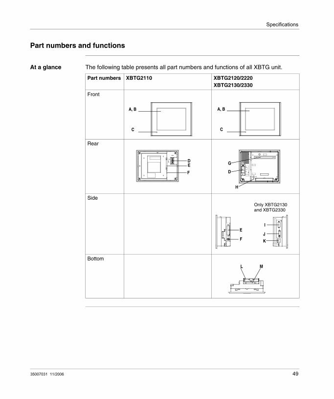
At a glance The following table presents all part numbers and functions of all XBTG unit.
Part numbers XBTG2110 XBTG2120/2220XBTG2130/2330
Front
Rear
Side
Bottom
A, B
C
A, B
C
ED
F
G
D
H
+-
E
F
I
JK
Only XBTG2130and XBTG2330
L M
35007031 11/2006 49

Specifications
Description The following table present description of part numbers for XBTG2110/2120/2220/2130/2330.
Letter Description
A Display: displays User created screens and Remote Equipment Variables.
B Touch Panel: performs screen change operations and sends data to the host (PLC).
C Power LED: XBTG2110: LED "ON", when power is supplied (Green LED).XBTG2120/2220/2130/2330 status with LED status:
Led Green: normal operation,Led Orange: backlight is not functionning.
D Power Input Terminal Block: connects the XBTG power cable's input and ground wires to the XBTG.
E Serial I/F (host I/F 25 pin): connects an RS-232C or RS-422 (Serial) cable (from the host/PLC) to the XBTG. Also for connecting a barcode reader.
F Tool Port Connector: connects the Data Transfer Cable to the XBTG.
G Expansion Unit I/F: connects expansion units with communication features.
H CF Card Access LED: if the CF Card Cover is closed when the CF Card is inserted, the LED lamp turns ON. The LED lamp will remain turned ON even if the CF Card Cover is opened while the XBTG accesses the CF Card.
I Expansion Serial Interface (SubD 9-pin). Only XBTG2130 and XBTG2330. Also for connecting a barcode reader.
J Printer connector, except XBTG2110/2120/2220/4320.
K Ethernet Interface (10Base T). Only XBTG2130and XBTG2330.
L CF Card Cover: open this cover to the CF Card Slot. When accessing the CF Card, this cover must be closed.
M CF Card I/F: insert the CF Card in this slot.
50 35007031 11/2006

Specifications
Description The following table presents all part numbers and functions of all XBTG unit.
Part numbers XBTG4320/4330 XBTG5230/5330XBTG6330
Front
Rear
Side
Bottom
A, B
C
A, B
C
L
D O E F K
G
IJ
N L
D N I
PM
H
F E J
H GK O
35007031 11/2006 51

Specifications
At a glance The following table present description of part numbers for XBTG4320/4330/5230/5330/6330.
Letter Description
A Display: displays User created screens and Remote Equipment Variables.
B Touch Panel: performs screen change operations and sends data to the host (PLC).
C Power LED: XBTG status with LED status:
Led Green: normal operation,Led Orange: backlight is not functionning.
D Power Input Terminal Block: connects the XBTG power cable's input and ground wires to the XBTG.
E Serial I/F (host I/F 25 pin): connects an RS-232C or RS-422 (Serial) cable (from the host/PLC) to the XBTG. Also for connecting a barcode reader.
F Serial Interface (SubD 9-pin): connects an RS-232C cable. Also for connecting a barcode reader. Except XBT-G4320.
G Not available.
H Ethernet Interface (10Base T). Except XBTG4320.
I CF Card Access LED: if the CF Card Cover is closed when the CF Card is inserted, the LED lamp turns ON. The LED lamp will remain turned ON even if the CF Card Cover is opened while the XBTG accesses the CF Card.
J CF Card slot: insert the CF Card in this slot.
K Tool Port Connector: connects the Data Transfer Cable to the XBTG.
L Expansion Unit interface 1: not available.
M CF Card Expansion interface: except XBTG4320 and XBTG4330.
N CF Card Cover: open this cover to the CF Card Slot. When accessing the CF Card, this cover must be closed.
O Screw Lock Terminal Block: Sound output interface. Used for sound output. Except XBTG4320.
P Expansion Unit interface 2: not available.
52 35007031 11/2006

Specifications
DIP Switches
At a glance Below the CF card cover, you can find DIP switches. Except for XBTG2110 all XBTG units have DIP switches.
Illustration
The following table explains XBTG units’ DIP switch parameters.
ON
1 2 3 4
Dip switch Function ON OFF Note
1 When there is no user application in the XBTG memory.
If the CF card includes an user application, downloads the application to the XBTG. Then, the XBTG runs the application.
A system message appears.
-
When there is an user application in the XBTG memory.
f the CF card includes an user application, downloads the application to the XBTG. Then, the XBTG runs the application.
Runs the user application on the XBTG.
2 Reserved. - - -
3 Reserved - - -
4 This setting controls the forced closing of the CF Card cover.
Forced close enabled. Forced close disabled.
Used when CF Card cover is damaged.
35007031 11/2006 53
Specifications
3.5 Dimensions
At a glance
Subject of this section
This section presents all dimensions’ XBTG units.
What's in this Section?
This section contains the following topics:
Topic Page
XBTG2110 dimensions 55
XBTG2120, XBTG2130, XBT-G2220, and XBTG2330 dimensions 56
XBTG4320 and XBTG4330 dimensions 57
XBTG5230, XBTG 5330 and XBTG6330 dimensions 58
Panel cut dimensions 59
Installation Fasteners 60
54 35007031 11/2006

Specifications
XBTG2110 dimensions
XBTG2110 The following figures present all dimensions of XBTG2110 unit.
Installation with fasteners
The following figures present all external dimensions of XBTG2110 unit with installation fasteners.
SideFront
Top
191.2 [7.53]
207 [8.15] 58 [2.28]
6 [0.24]
141.
2 [5
.56]
157
[6.1
8]
mm[in.] Top
mm[in.]125 [4.92]
62.5 [2.46]15
3.2
[6.0
3]
207 [8.15]
76.6
[3.0
2]
163.
2 [6
.43]
35007031 11/2006 55

Specifications
XBTG2120, XBTG2130, XBT-G2220, and XBTG2330 dimensions
XBTG2120, XBTG2130, XBTG2220, and XBTG2330
The following figures present all external dimensions of XBTG2120, XBTG2130, XBTG2220, and XBTG2330 unit.
Installation with fasteners
The following figures present all external dimensions of XBTG2120, XBTG2130, XBT-G2220, and XBTG2330 unit with installation fasteners.
155.5 [6.12]
171 [6.73] 60 [2.36]5 [0.20]
Front Top Side
138
[5.4
3]
123
[4.8
4]
mm[in.]
mm[in.]
136
[5.3
5]
68 [2
.68]
60 [2.36]5 [0.20]
126 [4.96]63 [2.48]
171 [6.73]
146
[5.7
5]
56 35007031 11/2006

Specifications
XBTG4320 and XBTG4330 dimensions
XBTG4320 and XBTG4330
The following figures present all external dimensions of XBTG4320 and XBTG4330 units.
Installation with fasteners
The following figures present all external dimensions of XBTG4320 and XBTG4330 units with installation fasteners.
mm[in.]
Front Side
Top
215 [8.46]
170
[6.6
9]
204 [8.03]
60 [2.36]8 [0.31]
159
[6.2
6]mm[in.] 135 [5.31]
67.5 [2.66]17
1 [6
.73]
85.5
[3.3
7]
8 [0.31]60 [2.36]215 [8.46]
181
[7.1
3]
35007031 11/2006 57

Specifications
XBTG5230, XBTG 5330 and XBTG6330 dimensions
XBTG5230, XBT-G5330 and XBT-G6330
The following figures present all external dimensions of XBTG5230, XBTG5330 and XBTG6330 unit.
Installation with fasteners
The following figures present all external dimensions of XBTG5230, XBTG5330 and XBTG6330 unit with installation fasteners.
mm[in.]
317 [12.48]24
3 [9
.57]
58 [2.28]8 [0.31]
227
[8.9
4]
Front
Side
Top
301 [11.85]
mm[in.]270 [10.63]
135 [5.31]
317 [12.48]
249
[9.8
0]
239
[9.4
1]
119.
5 [4
.70]
58 [2.28]8 [0.31]
58 35007031 11/2006
Specifications
Panel cut dimensions
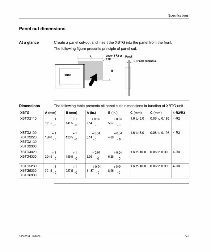
At a glance Create a panel cut-out and insert the XBTG into the panel from the front.
The following figure presents principle of panel cut.
Dimensions The following table presents all panel cut’s dimensions in function of XBTG unit.
XBTG
under 4-R2 or4-R3
A
B
PanelC : Panel thickness
XBTG A (mm) B (mm) A (in.) B (in.) C (mm) C (mm) 4-R2/R3
XBTG2110 1.6 to 5.0 0.06 to 0.195 4-R2
XBTG2120XBTG2220XBTG2130XBTG2330
1.6 to 5.0 0.06 to 0.195 4-R3
XBTG4320XBTG4330
1.6 to 10.0 0.06 to 0.39 4-R3
XBTG5230XBTG5330XBTG6330
1.6 to 10.0 0.06 to 0.39 4-R3
191.5+ 1
- 0141.5
+ 1
- 07.54
+ 0.04
- 05.57
+ 0.04
- 0
156.0+ 1
- 0123.5
+ 1
- 06.14
+ 0.04
- 04.86
+ 0.04
- 0
204.5+ 1
- 0159.5
+ 1
- 08.05
+ 0.04
- 06.28
+ 0.04
- 0
301.5+ 1
- 0227.5
+ 1
- 011.87
+ 0.04
- 08.96
+ 0.04
- 0
35007031 11/2006 59

Specifications
Installation Fasteners
At a glance The following drawing details the dimensions of the fasteners XBTZGSET.
31[1.22]
19.5[0.77]
16[0.63]
11[0
.43]
10[0
.39]
M5
60 35007031 11/2006

35007031 11/2006
4
Installation and wiringAt a glance
Subject of this chapter
This chapter describes installation procedures and wiring principle.
What's in this Chapter?
This chapter contains the following sections:
Section Topic Page
4.1 Installation 63
4.2 Wiring Precautions 65
4.3 Tool Port Connector 72
4.4 Ethernet Cable Connector 77
4.5 Printer Cable Connector 78
4.6 CF Card Installation and Removal 81
4.7 Sound Output 84
61

Installation and wiring
62 35007031 11/2006

Installation and wiring
4.1 Installation
Installation procedures
At a glance Before installing the XBTG into a cabinet or panel read the notes below.
The installation gasket, installation brackets and attachment screws are all required when installing the XBTG.
Note Gasket’s precautions:
Before installing the XBTG into a cabinet or panel, check that the Installation gasket is securely attached to the unit.A gasket which has been used for a long period of time may have scratches or dirt on it, and could have lost much of its dust and drip resistance. Be sure to change the gasket periodically, or when scratches or dirt become visible.Do not insert the joint of the installation gasket in the corner of the XBTG. If you do it, the joint will be pulled so that it may cause the installation gasket to be torn.
Panel’s precautions:
Check that the installation panel or cabinet’s surface is flat, in good condition and has no jagged edges. Also, if desired, metal reinforcing strips can be attached to the inside of the panel, near the Panel Cut, to increase the panel’s strength. Panel thickness (see Panel cut dimensions, p. 59) depends of XBTG unit. Decide the panel’s thickness based on the level of panel strength required.Be sure that the ambient operation temperature and the ambient humidity are within their designated ranges. (When installing the XBTG in a cabinet or enclosure, the term "ambient operation temperature" indicates the cabinet or enclosure’s internal temperature. Be sure that heat from surrounding equipment does not cause the XBTG to exceed its standard operating temperature.When installing the XBTG in a slanted panel, the panel face should not incline more than 30°.When installing the XBTG in a slanted panel, and the panel face inclines more than 30°, the ambient temperature must not exceed 40 °C. You may need to use forced air cooling (fan, A/C) to ensure the ambient operating temperature is 40 °C or below.When installing the XBTG vertically, position the unit so that the Power Input Terminal Block is also vertical.
35007031 11/2006 63

Installation and wiring
For easier maintenance, operation, and improved ventilation, be sure to install the XBTG at least 100 mm [3.94 in.] away from adjacent structures and other equipment.
Fastener’s precautions:
The minimum number of fasteners required to install a XBTG unit is four (4).Ten fasteners can be used only on a XBTG5230/5330/6330 unit.For XBTG2110 two additional slots for fasteners on both sides of the XBTG unit can be used, if greater strength is needed.For XBTG4320 do not use the attachment holes in the middle of sides panels.
Procedure The following table presents procedure for installing the XBTG.
100[3.94]
100[3.94]
100[3.94] 100[3.94]
100[3.94]
100[3.94]
100[3.94]
Step Action
1 It is strongly recommended that you use the installation gasket, since it absorbs vibration in addition to repelling water.Place the XBTG on a level surface with the display panel facing downward.
2 Check that the XBTG’s installation gasket (see Regular Cleaning, p. 106) is seated securely into the gasket’s groove, which runs around the perimeter of the panel’s frame.
3 Create the correct sized opening required to install the XBTG, using the installation dimensions (see Panel cut dimensions, p. 59) given.
4 Insert the XBTG into the panel cut out, as shown here.
5 Insert the installation fasteners into the XBTG’s insertion slots, at the top and bottom of the unit (total: 4 slots). Be sure to pull the fastener back until it is flush with the rear of the attachment hole.
6 Tighten each fastener with a screwdriver. The necessary torque is 0.5 Nm (4.4 lb-in).
64 35007031 11/2006
Installation and wiring
4.2 Wiring Precautions
At a glance
Subject of this section
This section presents principle of XBTG wiring.
What's in this Section?
This section contains the following topics:
Topic Page
Connecting the Power Cord 66
Connecting the Power Supply 68
Grounding 69
Input/Output Line placement 71
35007031 11/2006 65

Installation and wiring
Connecting the Power Cord
At a Glance
Ring terminal
Note: When the FG terminal is connected, be sure the wire is grounded. Not grounding the XBTG unit will result in excessive noise. Grounding is required to assure EMC level immunity.To prevent the Ring Terminals from causing a short when the terminal block attachment screws are loosened, be sure to use insulating-type Ring Terminals.The SG and FG terminals are connected internally in the XBTG unit.When connecting the SG line to another device, be sure that the design of the system/connection does not produce a shorting loop.
Note: Wherever possible, use thick wires (max. 2 mm [AWG 12 max]) for power terminals, and twist the wire ends before attaching the ring terminals.Be sure to use the following size ring terminals.To avoid a short caused by loose ring terminals, be sure to use ring terminals with an insulating sleeve.
Size of ring terminal: Over φ 3.2 mm [0.13 in]
Under 6.0 mm[0.24 in]
66 35007031 11/2006

Installation and wiring
Power input terminal block
Each XBTG unit has a Power input terminal block (see Part numbers and functions, p. 49).
The following table presents description of Power input terminal block elements.
Connecting the Power Supply Terminals
When connecting the power cord, be sure to follow the procedures given below.
Element Description
+ Positive terminal.
- Negative terminal.
FG Grounding Terminal connected to XBTG chassis.
+ - FG
Power input terminal block
Ring terminalsRear of XTB-G
+ - FG
Step Action
1 Remove all power to XBTG.
2 Remove the Clear plastic cover on the terminal block.
3 Remove the screws from the middle three terminals.
4 Insure the proper wire is installed into the correct position on the terminal block using ring terminals on the wire ends.
5 Confirm the correct connection points.
6 Torque the mounting screws to the required torque.
7 Replace the terminal cover.
Note: The torque required to tighten these screws is 0.5 Nm (4.4 lb-in).
35007031 11/2006 67

Installation and wiring
Connecting the Power Supply
At a glance Precaution:
To increase the noise resistance quality of the power cable, simply twist each power wire before attaching the Ring Terminal.The power supply cable must not be bundled or positioned close to main circuit lines (high voltage, high current), or input/output signal lines.Connect a lightning surge absorber to deal with power surges.
Be sure to ground the surge absorber (E1) separately from the XBTG unit (E2).Select a surge absorber that has a maximum circuit voltage greater than that of the peak voltage of the power supply.To avoid excess noise, make the power cable as short as possible.
XBTG unit
FG
lightningsurgeabsorber
E2
E1
68 35007031 11/2006

Installation and wiring
Grounding
Exclusive Grounding
Connect the FG terminal found at the back of the XBTG to an isolated ground.
Common Grounding
If exclusive grounding is not possible, use a common connection point.
CAUTIONGROUDING
Donot use common grouding, since it can lead to an accident or machine breakdown.
Failure to follow this instruction can result in injury or equipment damage.
XBTG UnitOther
Equipment
XBTG UnitOther
Equipment
XBTG UnitOther
Equipment
This grounding is not OK:
This grounding is OK:
35007031 11/2006 69
Installation and wiring
Note: Check that the grounding resistance is less than 100Ω (1).The SG and FG terminals are connected internally in the XBTG unit.When connecting the SG line to another device, be sure that the design of the system/connection does not produce a grounding loop.The grounding wire should have a cross sectional area greater than 2mm (1). Create the connection point as close to the XBTG unit as possible, and make the wire as short, as possible. When using a long grounding wire, replace the thin wire with a thicker wire, and place it in a duct.If the equipment does not function properly when grounded, disconnect the ground wire from the FG terminal.
(1): Use a grounding resistance of less than 100Ω and a 2mm or greater thickness wire, or your country’s applicable standard. For details, contact your local Schneider Electric distributor.
70 35007031 11/2006

Installation and wiring
Input/Output Line placement
At a glance Input and output signal lines must be separated from the power control cables for operating circuits.
If this is not possible, use a shielded cable and connect the shield to the XBTG’s frame.
35007031 11/2006 71

Installation and wiring
4.3 Tool Port Connector
At a glance
Subject of this section
This section presents principle of Tool Port Connector installation.
What's in this Section?
This section contains the following topics:
Topic Page
Tool Port Connector 73
USB Data Transfer Cable (XBTZG925) - Installation 74
72 35007031 11/2006

Installation and wiring
Tool Port Connector
At a Glance The XBTG’s Data Transfer Cables XBTZG915 and XBTZG925 can be attached to the XBTG unit’s Tool Port Connector (see Part numbers and functions, p. 49).
The following table presents Tool Port Connector location.
XBTG Unit Tool Port Connector location
Rear face of: XBTG2110
Right face of: XBTG2120 XBTG2130 XBTG2220 XBTG2330
Rear face of: XBTG4320
Bottom face of: XBTG4330 XBTG5230 XBTG5330 XBTG6330
Tool Port Connector
Tool Port Connector
Tool Port Connector
Tool Port Connector
35007031 11/2006 73

Installation and wiring
USB Data Transfer Cable (XBTZG925) - Installation
Overview The USB Data Transfer Cable is used to download data from the PC where Vijeo-Designer runs to the XBTG unit. It connects to the Tool Port of the XBTG.
Installation requirements
The PC must run on Microsoft Windows 2000 or Windows XP
You will need the installation CD for Vijeo-Designer.
Installation procedure for Windows 2000
Use the following procedure with Windows 2000
CAUTIONUSB CABLE CONNECTING/DISCONNECTINGWhen connecting the USB Data Transfer Cable to the PC or to the XBTG unit, be sure to insert the cable’s connector at the correct 90° angle. Failure to do so may damage either the connector or the unit.When disconnecting the cable, be sure to hold the connector, not the cable itself.If the cable is unplugged from the port designated during installation and connected to a different port, the Operating System (OS) will recognize the new port. Therefore, be sure to always use the port designated during installation.
If the installation does not complete successfully, restart the PC and quit all resident applications before re-installing the software.
Failure to follow this instruction can result in injury or equipment damage.
Step Action1 Start Windows, and connect the XBTZG925 cable to your PC’s USB port at one end,
and to the XBTG’s tool port at the other end.
2 Insert the Vijeo-Designer CD into the CD-ROM drive.
3 The New Hard Wizard dialog box appears. Click Next.4 Check the Search for a suitable driver for my device [recommended] option, and
click Next.5 In the following dialog box, check the Specify a location option, and click Next.6 Click Browse in the following dialog box, select the SERWPL.INF file located in the
CD-ROM’s folder XBTZG925, and click Open.
7 The driver for the XBTZG925 appears in the following dialog box. Click OK.
8 Confirm that The wizard found a driver for the following device: is Telemecanique XBTZG925, and click Next.
9 Click Finish to complete the installation.
74 35007031 11/2006

Installation and wiring
Installation procedure for Windows XP
Use the following procedure with Windows XP
Post-Installation Check
It is a good idea to do the following check after installation
Changing the COM Port Number
The COM number 3 is assigned automatically by the OS. If the OS had previously allocated COM numbers for other devices (Internal modems, IrDA ports, etc), the XBTZG925 will be allocated to the next available COM number. It is possible however to change the COM port number if required. To do so:
Step Action
1 Start Windows, and connect the XBTZG925 cable to your PC’s USB port at one end, and to the XBTG’s tool port at the other end.
2 Insert the Vijeo-Designer CD into the CD-ROM drive.
3 The Found New Hard Wizard dialog box appears. Check the Install from a list or specific location (Advanced) option, and click Next.
4 In the following dialog box, check the Include this location in the search: option, and click Browse.
5 Select the XBTZG925 folder in the installation CD-ROM, and click OK.
6 In the Found New Hardware Wizard screen, click Next.
7 The Telemecanique XBTZG925 driver now appears in the Hardware Installation screen. Click Continue Anyway.
8 Click Finish in the following screen to complete the installation.
Step Action
1 In the Configuration Panel, click on System Properties and select Device Manager.
2 Confirm that Telemecanique XBTZG925 COM3 is available in the Ports [COM & LPT] sub-folder.
Step Action
1 In the Configuration Panel, click on System Properties and select Device Manager.
2 Click on Ports [COM & LPT], select Telemecanique XBTZG925 COM3 and click on Properties.
3 In the Telemecanique XBTZG925 [COM3] Properties dialog box, click on the Port Settings tab, and click the Advanced button.
4 At the bottom of the following dialog box (Advanced Settings for COM1), select an unused number for the COM Port Number and click OK.
5 When the following Communication Port Properties dialog box appears, click Yes.
35007031 11/2006 75

Installation and wiring
Troubleshooting The following table describes errors that may occur and their possible solutions.
Uninstalling the Driver
Unplug the USB Data Transfer Cable the PC and double-click on the CD-ROM’s DRemover98_2K.exe file to start the uninstallation process.
Problem/Symptom Solution
The USB cable is not recognized. Connect the cable correctly. Or restart you PC. Also, when connecting a USB hub, be sure to connect it directly to your PC’s USB port.
Overcurrent occurred
The Plug and Play is not functioning correctly
You are unable to use the USB cable after connecting it to a USB hub.
The power supplied from the hub may be insufficient. Be sure the hub is self-powered.
Connect the cable directly to the PC USB port.
After installation, a "?" is displayed when you try to confirm the cable’s status via the Device Manager.
The driver has not been installed correctly. Uninstall the driver and re-install it.
76 35007031 11/2006

Installation and wiring
4.4 Ethernet Cable Connector
Ethernet Cable Connector
At a Glance The XBTG Ethernet interface is IEEE802.3 compliant, and transmits data at 10Mbps. XBTG units wich have got a RJ-45 Ethernet Cable Connector (see Part numbers and functions, p. 49), are:
XBTG2130,XBTG2330,XBTG4330,XBTG5230,XBTG5330,XBTG6330.
The following figure presents Ethernet Cable Connector location.
Note: It is strongly recommended that your Ethernet network is installed by a trained engineer.You may be able to use the 1:1 connection by a cross cable depending on PCs or network cards. Be sure to connect those with a hub or a switch.
Left face ofXBTG2130 and XBTG2330
Ethernet Cable Connector
Bottom face of XBTG4330, XBTG5230, XBTG5330 and XBTG6330
35007031 11/2006 77

Installation and wiring
4.5 Printer Cable Connector
Printer cable connector
Connection with parallel port
For parallel printer connection, respect following diagram:
The following table show the printer interface connector location:
XBTG2130 and XBTG2330
XBTG4320/4330
XBTG5230/5330 and XBTG6330
XBTZG946XBTG Unit
Printer port
Printer port
Printer port
78 35007031 11/2006

Installation and wiring
Printer interface When connecting a printer on parallel port, use XBTZG946 cable.
The printer interface is centronics compliant.
Pin Assignments Pin # Signal Name Condition
1 GND Ground
2 RESERVE Reserved
3 PDB5 Data Signal
4 PDB4 Data Signal
5 PDB3 Data Signal
6 GND Ground
7 SLCT Select Status (Input)
8 PDB0 Data Signal
9 PST B Strobe Signal (Onput)
10 BUSY Busy Signal (Input)
11 PDB7 Data Signal
12 PDB6 Data Signal
13 GND Ground
14 ERROR Printer Error (Input)
15 GND Ground
16 PDB2 Data Signal
17 PDB1 Data Signal
18 PE Paper Runout
19 INIT Initialization Signal (Output)
20 GND Ground
20
111
10
35007031 11/2006 79
Installation and wiring
Connection with serial port
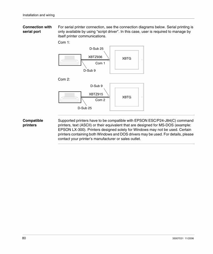
For serial printer connection, see the connection diagrams below. Serial printing is only available by using "script driver". In this case, user is required to manage by itself printer communications.
Com 1:
Com 2:
Compatible printers
Supported printers have to be compatible with EPSON ESC/P24-J84(C) command printers, text (ASCII) or their equivalent that are designed for MS-DOS (example: EPSON LX-300). Printers designed solely for Windows may not be used. Certain printers containing both Windows and DOS drivers may be used. For details, please contact your printer’s manufacturer or sales outlet.
XBTZ936 XBTG
D-Sub 25
Com 1
D-Sub 9
XBTZ915XBTG
D-Sub 9
D-Sub 25
Com 2
80 35007031 11/2006

Installation and wiring
4.6 CF Card Installation and Removal
CF Card Installation and Removal
Precautions When using the XBTG Unit and a CF Card, follow the precautions below:
Prior to inserting or removing a CF Card, be sure to turn the XBTG unit’s CF Card ACCESS switch OFF and to confirm that the ACCESS lamp is not lit. If you do not, CF Card internal data may be damaged or lost.Check that the DIP switch setting is appropriate. See DIP Switches, p. 53 While a CF Card is being accessed, NEVER turn OFF or reset the XBTG, or insert or remove the CF Card. Prior to performing these operations, create and use a special XBTG application screen that will prevent access to the CF Card.Prior to inserting a CF Card, familiarize yourself with the CF Card’s front and rear face orientation, as well as the CF Card connector’s position. If the CF Card is not correctly positioned when it is inserted into the Mulit Unit, the CF Card’s internal data and the XBTG unit may be damaged or broken.Be sure to use only CF Cards manufactured by Schneider Electric. XBTG unit performance cannot be guaranteed when using another manufacturer’s CF Card.Once XBTG data is lost, it cannot be recovered. Since accidental data loss can occur at any time, be sure to back up all XBTG screen and CF Card data regularly.Be sure to follow the instructions given below to prevent the CF Card’s internal data from being destroyed or a CF Card malfunction from occuring:
DO NOT bend the CF Card.DO NOT drop or strike the CF Card against another object.Keep the CF Card dry.DO NOT touch the CF Card connectors.DO NOT disassemble or modify the CF Card.
35007031 11/2006 81

Installation and wiring
Inserting the CF Card
Use the following steps to insert the CF Card in the XBTG unit (except XBT-G2110).
Removing the CF Card
Simply reverse the steps shown in the previous "Inserting CF Card" explanation. Prior to removing the CF Card, confirm that the CF Card Access LED is turned OFF.
Step Action
1 Slide the CF Card Cover in the direction shown here, then upwards to open the cover..
2 Insert the CF Card in the CF Card Slot, until the ejector button is pushed forward..
3 Close the cover. (As shown.).
4 Confirm that the CF Card Access LED turns ON.You cannot access to the CF Card with the CF Card cover opened. However, if the CF Card is being accessed, the access will be continued even if you open it on the way.
82 35007031 11/2006
Installation and wiring
CF Card Handling
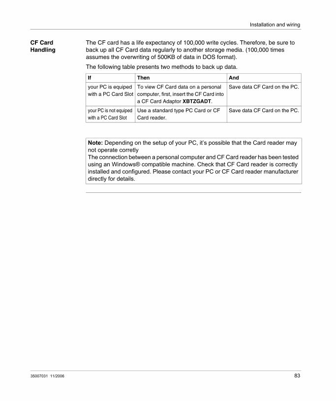
The CF card has a life expectancy of 100,000 write cycles. Therefore, be sure to back up all CF Card data regularly to another storage media. (100,000 times assumes the overwriting of 500KB of data in DOS format).
The following table presents two methods to back up data.
If Then And
your PC is equiped with a PC Card Slot
To view CF Card data on a personal computer, first, insert the CF Card into a CF Card Adaptor XBTZGADT.
Save data CF Card on the PC.
your PC is not equiped with a PC Card Slot
Use a standard type PC Card or CF Card reader.
Save data CF Card on the PC.
Note: Depending on the setup of your PC, it’s possible that the Card reader may not operate corretlyThe connection between a personal computer and CF Card reader has been tested using an Windows® compatible machine. Check that CF Card reader is correctly installed and configured. Please contact your PC or CF Card reader manufacturer directly for details.
35007031 11/2006 83

Installation and wiring
4.7 Sound Output
Sound Output
At a Glance This Procedure does apply to XBTG unit:
XBTG4330,XBTG5230,XBTG5330,XBTG6330.
Procedure Use the following steps to connect the speaker.
Step Action
1 Rotate the screw lock terminal block’s two (2) levers in the direction downward, and remove the screw lock terminal block.
2 Unscrew #11 pin and #10 pin set screws (2nd and 3rd screws from the left).
3 Insert the Speaker’s GND line in #11 pin connector, and the SP OUT line in #10 pin connector.
4 Confirm that each line (cable) is inserted completely, and retighten the two (2) set screws.
5 Reattach the screw lock terminal block to the XBTG.
Note: The torque required to tighten these screws is 0.5 Nm (4.4 lb-in).Sound file format is .wav, PCM 16 bits, 11,025 Khz mono.
84 35007031 11/2006
35007031 11/2006
II
Settings and debuggingAt a Glance
Subject of this part
This part describes types of settings and how to debug XBTG unit.
What's in this Part?
This part contains the following chapters:
Chapter Chapter Name Page
5 Settings 87
6 Troubleshooting 97
7 Maintenance 105
85

Settings and debugging
86 35007031 11/2006

35007031 11/2006
5
SettingsAt a Glance
Subject of this chapter
This chapter presents types of settings.
What's in this Chapter?
This chapter contains the following sections:
Section Topic Page
5.1 XBTG settings 89
87

Settings
88 35007031 11/2006

Settings
5.1 XBTG settings
At a Glance
Subject of this section
This section describes types of settings for all XBTG units.
What's in this Section?
This section contains the following topics:
Topic Page
Types of Settings 90
Offline settings 91
System settings 93
35007031 11/2006 89
Settings
Types of Settings
At a Glance The settings required for the XBTG unit, when starting Vijeo-Designer Runtime or when in RUN mode, are found in the Settings Menu.
The following table presents procedure how to call up Settings menu.
Step Action
1 Connect the XBTG unit’s power supply.
2 Depending of the "To configuration" property value configured under Vijeo-designer for the target. You can access or not to the settings menu by the following manner:
after the XBTG starts up, touch the upper left corner of the screen within 10 seconds to call up the menu,you can also enter Setting mode at any time by simultaneously touching the upper right corner, bottom right corner, and bottom left corner of the screen. Vijeo Designer Runtime will restart and the Settings Menu will appear.
3 In this mode, the two tabs, Offline and System are available. Simply touch the desired tab to bring up those settings.
90 35007031 11/2006

Settings
Offline settings
Offline tab The following figure presents Offline tab for units:
XBTG2110,XBTG2120,XBTG2130,XBTG2220,XBTG2330.
The following figure presents Offline tab for units:
XBTG4320,XBTG4330,XBTG5320,XBTG5330,XBTG6330.
To Run Mode
SystemOffline
Buzzer
Network
Self Test
Backlight
To Run Mode
System SettingsOffline Settings
Network Buzzer Backlight Self Test
35007031 11/2006 91

Settings
Network settings The following table explains how to enter XBTG unit’s network settings. This cannot be set XBTG2110/2120/2220/4320 Series units.
Touch Buzzer The following table explains how to enter XBTG unit’s buzzer sound settings.
Backlight Control
The following table explains how to enter XBTG unit’s Backlight Control settings.
Self Test Performs the XBTG unit’s self test (see Self Test, p. 101).
Step Action1 In the Settings menu, touch the Offline tab.
2 Touch the Network icon.
3 Touch/select any of the three fields (IP Address, Subnet Mask, or Default Gateway) and a keypad will appear for data entry.
Note: After making a change to the Network settings, be sure to restart the XBT-G unit. Touching the Network screen’s XBTG key will automatically restart the XBT-G.
Step Action1 In the Settings menu, touch the Offline tab.
2 Touch the Buzzer icon.
3 Touch/select the desired buzzer mode.The factory setting is When Press Touch Object.
None: Selecting this will turn the buzzer off.When Press Touch Object: The buzzer will only sound when a Touch Object is touched.
Step Action1 In the Settings menu, touch the Offline tab.
2 Touch the Backlight icon.
3 Touch/select the desired backlight brightness.Here, two selections (modes) are available.
Wait: to preserve the XBTG unit’s screen display elements and extend the life of the backlight, the backlight can be set to automatically turn off after a designated period of inactivity (idle time) elapses. The factory setting for this item is OFF.Enable Touch if Backlight is Burned Out: this setting designates if the touch panel is enabled or disabled when a backlight burnout is detected. When this feature is set to OFF, touch panel touch input is ignored, while the backlight is off, thereby preventing touch panel operation errors. The factory setting is OFF. (Checkbox is not set.)
4 To automatically turn the backlight off after a specified period of time, touch the Wait selection and set the idle time period.
92 35007031 11/2006

Settings
System settings
System tab The following figure presents System tab for units:
XBTG2110,XBTG2120,XBTG2130,XBTG2220,XBTG2330.
The following figure presents System tab for units:
XBTG4320,XBTG4330,XBTG5320,XBTG5330,XBTG6330.
To Run Mode
Date/Time
Stylus Ver. Info
Language
SystemOffline
Restart
Memory
Brightness
Option
To Run Mode
System SettingsOffline Settings
Stylus Date/Time Restart Ver. Info
Language Memory
Configuration Mode
Brightness Option
ON
OFF
35007031 11/2006 93

Settings
Stylus This setting is not supported now for XBTG series units.
Date/Time The following table explains how to enter XBTG unit’s Date/Time settings.
Restart System The following table explains how to restart XBTG unit.
Version Information
The following table explains how to access XBTG unit’s Version Information.
Language Selection
The following table explains how to designates the language used with System screens and User Applications in XBTG unit’s.
Memory The following table explains how to displays the total amount of memory, and the amount of memory currently being used.
Step Action1 In the Settings menu, touch the System tab.
2 Touch the Date/Time icon.
3 Touch/select the Date or Time field to call up a data entry keypad. Use this keypad to enter all time settings.
Step Action1 In the Settings menu, touch the System tab.
2 Touch the Restart icon.
3 Touch/select the Restart button to restart the XBTG unit.
Step Action1 In the Settings menu, touch the System tab.
2 Touch the Ver. Info icon.Calls up the Vijeo Designer runtime version, and the version and build numbers for the Vijeo-Designer version used to design the project.
Step Action1 In the Settings menu, touch the System tab.
2 Touch the Language icon.Touch/select the desired language for the System and User Application items.
Step Action1 In the Settings menu, touch the System tab.
2 Touch the Memory icon.
94 35007031 11/2006
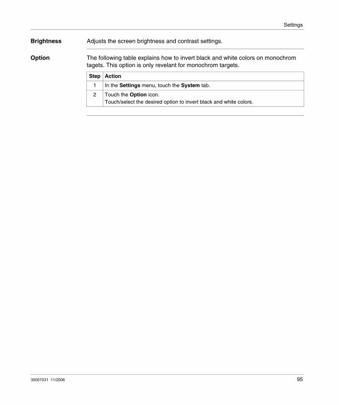
Settings
Brightness Adjusts the screen brightness and contrast settings.
Option The following table explains how to invert black and white colors on monochrom tagets. This option is only revelant for monochrom targets.
Step Action
1 In the Settings menu, touch the System tab.
2 Touch the Option icon.Touch/select the desired option to invert black and white colors.
35007031 11/2006 95

Settings
96 35007031 11/2006

35007031 11/2006
6
TroubleshootingAt a Glance
Subject of this Chapter
This chapter explains how to find and resolve XBTG unit problems.
What's in this Chapter?
This chapter contains the following sections:
Section Topic Page
6.1 Troubleshooting Checklists 99
6.2 Self Test 101
97

Troubleshooting
98 35007031 11/2006
Troubleshooting
6.1 Troubleshooting Checklists
Troubleshooting Checklists
At a glance When a problem occurs, be sure to follow each checklist item and follow the instructions given.
The main problems that occur during use of the XBTG unit are:
the panel display is blank,connected devices cannot be used.
Note: If this does not solve the problem, please contact your local Schneider Electric distributor.For hardware and software problems, contact the Schneider Electric distributor where you bought the XBTG unit.
35007031 11/2006 99

Troubleshooting
No display The table below presents a procedure to follow and countermeasure associated when the panel display is blank.
Devices cannot be used
The table below presents a procedure to follow and countermeasure associated when the connected devices cannot be used.
Step Check Item/Operation Countermeasure
1 Are all Vijeo Designer screens downloaded to the XBTG unit?
If not, download to the XBTG.
2 Is the Initial Panel ID set up correctly in Vijeo Designer?
If not, enter the Initial Panel ID and re-download the screen data.
3 Is the XBTG unit’s status LED lit? If the LED is orange, the backlight is burned out. Please change the backlight (see Replacing the backlight, p. 109).
4 Is the voltage level within the designated range?
Voltage level (see Electrical specifications, p. 32).
5 Turn the power supply OFF. -
6 Are the power cable terminals correctly connected?
If not, connect the terminals correctly (see Wiring Precautions, p. 65).
7 Turn the power supply ON. -
8 Is the power lamp lit? If not lit -> Hardware problem.
9 Is the backlight lit? If the backlight is burned out, please change the backlight (see Replacing the backlight, p. 109).
10 Did the above procedure correct the problem?
If not, -> Hardware problem.
Step Check Item/Operation Countermeasure
1 Turn the power supply OFF. -
2 Are the power cable terminals correctly connected?
If not, connect the terminals correctly (see Wiring Precautions, p. 65).
3 Is the correct Device/PLC protocol and driver information set up in Vijeo Designer?
If not, enter the correct protocol and driver information.
4 Is the Device/PLC connection cable correctly connected?
Refer to the Device/PLC’s manual and correctly (see Wiring Precautions, p. 65) connect the cable.
5 Did the above procedure correct the problem?
If not, -> Hardware problem.
100 35007031 11/2006

Troubleshooting
6.2 Self Test
Self test item list
At a glance The XBTG unit is equipped with a number of self diagnosis features used to check its System and Interfaces for any problems.
Self Test On Offline tab press on Self Test icon, Self Test tab appears.
The following figure presents Self Test tab for units:
XBTG2110,XBTG2120,XBTG2130,XBTG2220,XBTG2330.
Return
Self Test
COM 2
COM 1
Touch Panel
Disp. Pattern
Char. Pattern Video Memory
35007031 11/2006 101

Troubleshooting
The following figure presents Self Test tab for units:
XBTG4320,XBTG4330,XBTG5320,XBTG5330,XBTG6330.
Return
Self Test
COM 2
COM 1
Touch Panel
Disp. Pattern
Char. Pattern Video Memory
102 35007031 11/2006

Troubleshooting
Details This following table describes all icon’s Selt Test tab.
SIO Cable wiring The following figure presents loopback wiring for testing COM ports (COM1, COM2).
Icon Description
Char. Pattern Checks each font’s pattern and kanji-characters’ROM. Used when kanji-characters do not display. If there is no error, the message OK will appear, if there is an error, the message NG will appear.
Disp Pattern Used when the device contents will not display correctly to check the drawing function.
Touch Panel Touch Panel check. Checks if each touch cell highlights when pressed.
COM 1, COM 2 (1) Checks the RS-232C and RS-485 SIO lines for areas where communication problems develop. To run the check, connecting the SIO cable is necessary. If all is normal, OK displays; if there is a problem, an error message appears.
Video Memory This item is used to check video memory (memory used for screen display). Use this feature when your screen display is not correct. This result of this test will be either OK (no problem) or NG (problem).
Legend
(1): not available for XBTG2110/2120/2220/4320.
2
34
5820
COM1RS-232C
SD
RDRS
CSCDER
10
1115
161819
COM1RS-485
RDA
SDASDB
RDBCSBERBCSAERA
2122
1
23
456
COM2RS-232C
CD
RDSD
ERSGDR
7
89
RSCSRI
35007031 11/2006 103

Troubleshooting
104 35007031 11/2006

35007031 11/2006
7
MaintenanceAt a glance
Subject of this section
This section presents the maintenance principle of XBTG unit.
What's in this Chapter?
This chapter contains the following topics:
Topic Page
Regular Cleaning 106
Periodic check points 108
Replacing the backlight 109
105

Maintenance
Regular Cleaning
Cleaning the dispplay
When the surface or the frame of the display gets dirty, soak a soft cloth in water with a neutral detergent, wring the cloth tightly, and wipe the display.
Do not use hard or pointed objects to operate the touch-screen panel, since it can damage the panel surface.
Installation Gasket
The installation (see Installation procedures, p. 63) gasket protects the XBTG and improves its water resistance.
Procedure The following table presents operating mode to installation gasket.
Note: Do not use paint thinner, organic solvents, or a strong acid compound to clean the unit.
Note: A gasket which has been used for a long period of time may have scratches or dirt on it, and could have lost much of its water resistance. Be sure to change the gasket at least once a year, or when scratches or dirt become visible.
Step Action
1 Place the XBTG on a flat clean, level surface facing the display face downwards.
2 Remove the gasket from the XBTG.
3 Attach the new gasket (see Accessories, p. 26) to the XBTG. Be sure to insert the gasket into the XBTG’s groove so that the gasket’s groove sides are vertical.
4 Check if the gasket is attached to the XBTG correctly.
Gasket
Rear face
Gasket
106 35007031 11/2006

Maintenance
Note: The gasket must be inserted correctly into the groove for the XBTG’s moisture resistance to be equivalent to IP65f.Be sure the gasket’s seam is not inserted into any of the unit’s corners, only in the straight sections of the groove. Inserting it into a corner may lead to its eventually tearing.The upper surface of the gasket should protrude approximately 2mm out from the groove. Be sure to check that the gasket is correctly inserted before installing the XBTG into a panel.
2.0 mm [0.08 in.]
35007031 11/2006 107

Maintenance
Periodic check points
At a glance To keep your XBTG unit in its best condition, please inspect the following points periodically.
XBTG Operation Environment
Is the operating temperature within the allowable range (0°C to 50°C )(32°F 122°F)?Is the operating humidity within the specified range ((20%RH to 85%RH for XBTG2110) or 10%RH to 90%RH, dry bulb temperature of 39°C(102.2°F) or less)?Is the operating atmosphere free of corrosive gasses ?
Electrical Specifications
Is the input voltage within Ratings?XBTG2110: 20.4 to 27.6 Volts dc,All other XBTG models: 19.2 to 28.8 Volts dc.
Related Items
Are all power cords and cables connected properly? Have any become loose?Are all mounting brackets holding the unit securely?Are there many scratches or traces of dirt on the installation gasket?
108 35007031 11/2006

Maintenance
Replacing the backlight
At a glance You can replace XBTG’s backlight (see Accessories, p. 26) except for XBTG2110/2330.
For backlight replacement details, refer to the replacement backlight unit’s installation guide.
XBT-G2110/2330 The XBTG2110 and XBTG2330’s backlight can not be replaced by a user.
For backlight replacement, contact your local Schneider Electric distributor.
Principle When the unit’s backlight burns out, the unit’s status LED will turn orange. If the OFFLINE menu’s USE TOUCHPANEL AFTER BACKLIGHT BURNS OUT feature is set to NO, the XBTG’s touch panel will be disabled.
XBTG Series units use a CFL, long-life type backlight. The actual life of the backlight however, will vary depending on the XBTG’s operating conditions, and replacement may be required.
A XBTG Series backlight has a life, when the backlight is lit continuously (time required for brightness to fall to half its normal level.),
for XBTG2110 of 25,000 hours (approx. 2.8 years, at 25°C and 24 hour operation),for other XBTG of 50,000 hours (approx. 5.7 years, at 25°C and 24 hour operation).
35007031 11/2006 109

Maintenance
110 35007031 11/2006
CBAIndex
AAccessories, 26
CCE marking, 21CF Card
Installation, 81Connecting the Power Cord, 66Connecting the Power Supply, 68
EEthernet Cable Connector, 77
FFasteners, 60
GGrounding, 69
IInput/Output Line placement, 71Installation
CF Card, 81Fasteners, 60Procedures, 63
35007031 11/2006
PPackage Contents
XBTG, 19Part numbers
XBTG2110, 49XBTG2120, 49XBTG2130, 49XBTG2220, 49XBTG2330, 49XBTG4320, 51XBTG4330, 51XBTG5220, 51XBTG5330, 51XBTG6330, 51
Periodic Check points, 108
RRegular Cleaning, 106Replacing the Backlight, 109
SSelf Test, 101Sound Output, 84Specification
Clock, 38COM1, 43COM2, 46Display, 36electrical, 32Environmental, 33
111

Index
Interfaces, 39Memory, 38Other Interfaces, 47Structural, 34
STN, 18
TTFT, 18Tool Port Connector, 73Troubleshooting, 99
XXBTG
Accessories, 26DIP Switches, 53Edit mode peripherals, 24Installation, 63Overview, 18Package Contents, 19Run mode peripherals, 25Standards, 20
XBTG2110Dimensions, 55Offline Settings, 91Panel cut dimensions, 59Settings, 90System Settings, 93
XBTG2120Dimensions, 56Offline Settings, 91Panel cut dimensions, 59Settings, 90System Settings, 93
XBTG2130Dimensions, 56Offline Settings, 91Panel cut dimensions, 59Settings, 90System Settings, 93
112
XBTG2220Dimensions, 56Offline Settings, 91Panel cut dimensions, 59Settings, 90System Settings, 93
XBTG2330Dimensions, 56Offline Settings, 91Panel cut dimensions, 59Settings, 90System Settings, 93
XBTG4230Settings, 90
XBTG4320Dimensions, 57Offline Settings, 91Panel cut dimensions, 59Settings, 90System Settings, 93
XBTG4330Dimensions, 57Offline Settings, 91Panel cut dimensions, 59System Settings, 93
XBTG5230Dimensions, 58Offline Settings, 91Panel cut dimensions, 59Settings, 90System Settings, 93
XBTG5330Dimensions, 58Offline Settings, 91Panel cut dimensions, 59Settings, 90System Settings, 93
XBTG6330Dimensions, 58Offline Settings, 91Panel cut dimensions, 59Settings, 90System Settings, 93
35007031 11/2006
![H20youryou[2] · 2020. 9. 1. · 65 pdf pdf xml xsd jpgis pdf ( ) pdf ( ) txt pdf jmp2.0 pdf xml xsd jpgis pdf ( ) pdf pdf ( ) pdf ( ) txt pdf pdf jmp2.0 jmp2.0 pdf xml xsd](https://img.pdfslide.net/doc/110x75/60af39aebf2201127e590ef7/h20youryou2-2020-9-1-65-pdf-pdf-xml-xsd-jpgis-pdf-pdf-txt-pdf-jmp20.jpg)


