Embed Size (px)
Citation preview
Transmission System Guide Lines
Xcel Energy Operating Companies
Interconnection Guidelines for Transmission to Transmission Interconnections
Version: 9.0
File Name : XEL-POL-Transm-TransmInterconnectionGuidelines.doc Page 1 of 52
1.0 PURPOSE
This guideline describes the requirements for connecting a customer’s new transmission system or expanding a customer’s current transmission system to an electric transmission line or substation owned and operated by one of the Xcel Energy operating companies: Northern States Power Company (Minnesota) and Northern States Power Company (Wisconsin) (jointly NSP); Public Service Company of Colorado (PSCo); and Southwestern Public Service Company (SPS).
2.0 APPLICABILITY AND RESPONSIBILITIES
Xcel Energy Services Inc., the service company for the Xcel Energy Inc. holding company system
Xcel Energy Operating Companies
3.0 APPROVERS
Name Title
Brian R. Lorentz Director, Substation Operations & Maintenance
Ian R. Benson AVP, Transmission Strategy and Planning
Byron R. Craig Director, Subs & Trans Engineering and Design
Anthony T. Jandro AVP, Transmission Portfolio Delivery
Roger D. Hargreaves Director, System Operations
4.0 VERSION HISTORY
Date Version Number
Supercedes Change
8/23/2010 3.0 N/A Initial ProjectWise Document.
8/28/2013 4.0 3.0 General review and update.
10/1/2103 4.1 4.0 Made corrective changes to the document.
8/29/2014 5.0 4.1 General review and update.
8/31/2015 6.0 5.0 Annual review and update
8/31/2016 7.0 6.0 Annual review and update
8/31/2017 8.0 7.0 Annual review and update
8/31/2018 9.0 8.0 Annual review and update
Transmission System Guide Lines
Xcel Energy Operating Companies
Interconnection Guidelines for Transmission to Transmission Interconnections
Version: 9.0
File Name : XEL-POL-Transm-TransmInterconnectionGuidelines.doc Page 2 of 52
Policy
I.INTRODUCTION AND GENERAL POLICY 5
A. INTRODUCTION .................................................................................................................... 5
B. THE XCEL ENERGY SYSTEMS .................................................................................................. 6
C. GUIDELINE AUTHORITY ......................................................................................................... 8
D. GUIDELINE OBJECTIVES AND LIMITATIONS ............................................................................ 9
E. INTERCONNECTION PROCESS .............................................................................................. 10
F. FINANCIAL OBLIGATION OF THE INTERCONNECTION PARTY ................................................. 10
G. OWNERSHIP, OPERATION .................................................................................................... 10
H. OPERATION SUBJECT TO TRANSMISSION OPERATOR ............................................................ 11
I. NERC AND REGIONAL ENTITY POLICIES AND STANDARDS COMPLIANCE ................................... 11
II.INTERCONNECTION TECHNICAL REQUIREMENTS 13
A. TRANSMISSION INTERCONNECTION CONFIGURATION .......................................................... 13
B. MODELING INFORMATION ................................................................................................... 14
C PROTECTIVE DEVICES ......................................................................................................... 14
D. INTERFERENCE ................................................................................................................... 15
E. VOLTAGE, HARMONICS, AND FLICKER .................................................................................. 15
F. FREQUENCY AND FREQUENCY CONTROL .............................................................................. 16
G. TRANSMISSION LINE REACTIVE CAPABILITY ......................................................................... 16
H. FAULT CURRENT ................................................................................................................. 17
I. SYSTEM RESTORATION AND BLACK START CAPABILITY ......................................................... 17
J. DISCONNECT DEVICE/POINT OF DEMARCATION ................................................................... 17
K. EFFECTIVE GROUNDING ...................................................................................................... 17
III.EQUIPMENT, PROTECTION AND CONTROL REQUIREMENTS 19
A. FAULT CLEARING ................................................................................................................. 19
B. UTILITY GRADE RELAYS ....................................................................................................... 19
C. MINIMUM PROTECTION REQUIREMENTS ............................................................................... 20
D. REDUNDANT/BACKUP PROTECTION ...................................................................................... 20
E. SYNCHRONIZATION ............................................................................................................. 20
F. STATION POWER/STATION SERVICES ................................................................................... 21
G. GROUNDING SYSTEM .......................................................................................................... 21
Transmission System Guide Lines
Xcel Energy Operating Companies
Interconnection Guidelines for Transmission to Transmission Interconnections
Version: 9.0
File Name : XEL-POL-Transm-TransmInterconnectionGuidelines.doc Page 3 of 52
H. COMMUNICATION CHANNEL (S) ........................................................................................... 21
I. METERING AND TELEMETRY ................................................................................................ 21
J. SUPERVISORY CONTROL AND DATA ACQUISITION (SCADA) .................................................. 22
K. VOLTAGE AND BIL VALUES ................................................................................................... 22
L. REMEDIAL ACTION SCHEME ................................................................................................. 23
IV. INTERCONNECTION PROCESS 24
A. TRANSMISSION SERVICE REQUEST ...................................................................................... 24
B. TRANSMISSION TO TRANSMISSION INTERCONNECTION REQUESTS STEPS ............................. 24
V. ACCEPTANCE TESTING AND INSPECTION REQUIREMENTS 26
A. GENERAL ............................................................................................................................ 26
B. DEMONSTRATION................................................................................................................ 27
C. FUTURE CHANGES IN REQUIREMENTS .................................................................................. 29
D. PERFORMANCE OF TESTS .................................................................................................... 29
E. TESTING EQUIPMENT .......................................................................................................... 29
F. XCEL ENERGY SUPPLIED EQUIPMENT ................................................................................... 30
G. FINAL DESIGN/AS-BUILT DOCUMENTS .................................................................................. 30
VI.OPERATION AND MAINTENANCE GUIDELINES 31
A. NORMAL CONDITIONS ......................................................................................................... 31
B. ABNORMAL CONDITIONS ..................................................................................................... 31
C. ENERGIZATION OF XCEL ENERGY EQUIPMENT BY THE INTERCONNECTION PARTY ................. 31
D. MAINTENANCE NOTIFICATION ............................................................................................. 32
E. MAINTENANCE .................................................................................................................... 32
F. DESIGN CHANGES AFTER COMMERCIAL OPERATION ............................................................. 32
G. OPERATING DATA SUBMITTALS............................................................................................ 33
H. OPERATIONAL LOG .............................................................................................................. 33
I. COMMUNICATION WITH XCEL ENERGY OPERATIONS ............................................................ 33
VII.GLOSSARY 34
VIII. REFERENCES 41
APPENDIX B: XCEL ENERGY METERING AND TELEMETRY REQUIREMENTS 49
1. GENERAL ............................................................................................................................ 49
2. METERING ACCURACY, TESTING, AND REPAIR ...................................................................... 49
3. METERING AND TELEMETRY FUNCTION REQUIREMENTS ....................................................... 50

Transmission System Guide Lines
Xcel Energy Operating Companies
Interconnection Guidelines for Transmission to Transmission Interconnections
Version: 9.0
File Name : XEL-POL-Transm-TransmInterconnectionGuidelines.doc Page 4 of 52
Transmission System Guide Lines
Xcel Energy Operating Companies
Interconnection Guidelines for Transmission to Transmission Interconnections
Version: 9.0
File Name : XEL-POL-Transm-TransmInterconnectionGuidelines.doc Page 5 of 52
I. INTRODUCTION AND GENERAL POLICY
A. Introduction
The Interconnection Guidelines for Transmission to Transmission Interconnections (Guidelines) describe the
requirements for connecting a transmission system to an electric transmission system owned and operated by any of the following Xcel Energy operating companies: Public Service Company of Colorado (PSCX),
Southwestern Public Service Company (SPSX), or Northern States Power Company (Minnesota) or Northern States Power Company (Wisconsin) (jointly NSPX). For the balance of this document, the Xcel Energy utilities
will be jointly referred to as Xcel Energy or the Xcel Energy Operating Companies.
One purpose of these Interconnection Guidelines is to comply with the requirements of NERC standard FAC
001-0, Facility Connection Requirements, by maintaining and publishing facility connection requirements.
These Guidelines should thus be considered a "User's Guide" to the interconnection process for the Interconnection Party and Xcel Energy employees. To the extent possible, the Guidelines provide a universal set
of requirements for all Xcel Energy transmission systems. However, there are some technical requirements
specific to a state, Xcel Energy operating company or North American Electric Reliability Corporation (NERC) Reliability Region. The specific requirements are discussed in more detail below, where applicable. Each
such requirement is labeled with the Operating Company or Reliability Organization to which it applies.
In this document, certain words and abbreviations are identified as having specific meanings. These words and abbreviations are given in bold face type when initially defined. These words and abbreviations can also be
found in the GLOSSARY section of this document.
For example, for purposes of these Guidelines, the term Interconnection Party will be used to refer to transmission connections to Xcel Energy’s transmission system.
Transmission System Guide Lines
Xcel Energy Operating Companies
Interconnection Guidelines for Transmission to Transmission Interconnections
Version: 9.0
File Name : XEL-POL-Transm-TransmInterconnectionGuidelines.doc Page 6 of 52
B. The Xcel Energy Systems
1. DESCRIPTION OF XCEL ENERGY OPERATING COMPANIES
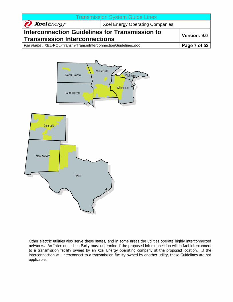
The Xcel Energy Operating Companies own and operate electric transmission systems in portions of 10
states. The applicable states are:
PSCX - Colorado
NSPX - Minnesota, North Dakota, South Dakota, Wisconsin, Michigan
SPSX - Texas, New Mexico, Kansas, Oklahoma
The following is a simple map showing the location of the transmission systems of each Xcel Energy
Operating Company.
Transmission System Guide Lines
Xcel Energy Operating Companies
Interconnection Guidelines for Transmission to Transmission Interconnections
Version: 9.0
File Name : XEL-POL-Transm-TransmInterconnectionGuidelines.doc Page 7 of 52
Other electric utilities also serve these states, and in some areas the utilities operate highly interconnected networks. An Interconnection Party must determine if the proposed interconnection will in fact interconnect
to a transmission facility owned by an Xcel Energy operating company at the proposed location. If the
interconnection will interconnect to a transmission facility owned by another utility, these Guidelines are not applicable.
Transmission System Guide Lines
Xcel Energy Operating Companies
Interconnection Guidelines for Transmission to Transmission Interconnections
Version: 9.0
File Name : XEL-POL-Transm-TransmInterconnectionGuidelines.doc Page 8 of 52
2. RELIABILITY REGIONS
The Xcel Energy Operating Company transmission systems are located in three NERC Reliability Regions. Each Reliability Region has certain requirements that are specific to that region. NERC has
delegated authority for Reliability Standard enforcement to the Regional Entities overseeing the various
Reliability Regions. The three Regional Entities applicable to Xcel Energy regions are the Midwest Reliability Organization (MRO), the Southwest Power Pool (SPP), and the Western Electricity Coordinating Council
(WECC). The applicable Reliability Regions for each of the Xcel Energy Operating Companies are as follows:
PSCX - WECC www.wecc.biz
NSPX - MRO www.midwestreliability.org
SPSX - SPP www.spp.org
3. OPEN ACCESS TRANSMISSION TARIFFS (OATT)
The Xcel Energy transmission systems are also subject to three different OATTs on file with the FERC. The Applicable OATT, and the web site address, are as follows:
PSCX - the Xcel Energy Joint OATT, available at www.rmao.com
NSPX - the Midcontinent Independent System Operator, Inc (MISO) regional OATT (MISO
OATT) available at www.midwestiso.org (click on "Latest Tariff" icon)
SPSX - SPP regional OATT (SPP OATT), available at http://sppoasis.spp.org/OASIS/SWPP
(click on “Regional Tariff” in the matrix of selections) or the Xcel Energy Joint OATT, available at
www.rmao.com
As indicated above, these Guidelines should be considered to be supplemental technical requirements to the procedures and requirements set forth in the applicable OATT. To the extent there is a conflict between
these Guidelines and the applicable OATT, the applicable OATT will control unless FERC has accepted the
Xcel Energy Guideline.
C. Guideline Authority
Several federal and state regulatory agencies have authority over the electric services provided by the Xcel Energy operating companies. The requirements set forth by this document are intended to comply with these
requirements, including the Federal Power Act (FPA), all local, state and federal regulatory agency requirements, and the applicable requirements of other entities related to owners and operators of electric
systems, such as NERC or the Regional Reliability Organization. The Interconnection Party should keep abreast
of changes in regulatory requirements and comply with them as they develop. Specifically:
FERC has authority over any interconnection to an Xcel Energy electric transmission system at transmission
voltage under the FPA. FERC’s Rules, and the individual OATTs implementing them (listed above), are subject to change from time-to-time. The Interconnection Party should consult the applicable OATT to ensure that the
most up to date OATT requirements are used in the project design, operation and maintenance requirements.
Transmission System Guide Lines
Xcel Energy Operating Companies
Interconnection Guidelines for Transmission to Transmission Interconnections
Version: 9.0
File Name : XEL-POL-Transm-TransmInterconnectionGuidelines.doc Page 9 of 52
NERC has established standards and practices for the reliable design and operation of the electric transmission
system. NERC and the individual Reliability Regions modify and update their requirements from time to time. The Interconnection Party should also consult the websites of NERC (www.nerc.com) and the applicable
Reliability Region (see above) to ensure that the most up-to-date requirements are used in the project design,
operation and maintenance requirements. This Guideline is periodically updated, but the Guideline may not reflect the most up-to-date information.
Various American National Standards Institute (ANSI) and Institute of Electrical and Electronic Engineers
(IEEE) standards also affect transmission interconnections and are mentioned in this Guideline. ANSI and IEEE update and revise these standards from time to time. The Interconnection Party should plan its interconnection
using the latest revision of referenced ANSI/IEEE standards because Xcel Energy considers them to be
automatically incorporated into this Guideline.
The transmission systems in the individual Xcel Energy operating companies are or may become part of an Independent System Operator (ISO), a Regional Transmission Organization (RTO), or an Independent
Transmission Company (ITC) at some time in the future. For the purposes of this document, the term ISO,
unless specified otherwise, will be used to indicate all such possible regional transmission entities. As such changes occur; the requirements imposed on Xcel Energy by the applicable ISO will affect Transmission
interconnections. Xcel Energy plans to update these Guidelines from time-to-time to incorporate the changing ISO requirements that become applicable, but the Interconnection Party should consult the ISO for any
applicable ISO requirements.
However, these Guidelines are not intended to modify any existing OATT or agreements that establish the rights
and obligations of Xcel Energy or the Interconnection Party. This document also is not intended to override or change any statutes, regulations or other applicable authority. In cases where national, Reliability Organization,
or state or local codes or regulations are in conflict with the provisions of these Guidelines, the national, state or local code will take precedence.
Since these Guidelines are subject to these various regulatory authorities, who are subject to change, Xcel Energy reserves the right to revise these Guidelines from time-to-time without advance notice.
D. Guideline Objectives And Limitations These Guidelines serve as a reference for establishing transmission interconnections to an Xcel Energy electric
transmission system (Xcel Energy System). The technical terms used in this guide are defined in the GLOSSARY.
Pursuant to the applicable OATT, Xcel Energy will permit any eligible Interconnection Party to operate
transmission equipment connected to an Xcel Energy System. The OATT and these Guidelines state the minimum requirements for independently owned transmission to safely and effectively interconnect to Xcel
Energy’s electric transmission system.
These Guidelines are formulated to provide the Interconnection Party with a reliable interconnection and
provide Xcel Energy with the flexibility and authority necessary to preserve reliability. All of the elements necessary for Xcel Energy to achieve this flexibility will normally be under the control of Xcel Energy. All of the
elements necessary for the Interconnection Party to control, operate, and maintain its interconnection facility
Transmission System Guide Lines
Xcel Energy Operating Companies
Interconnection Guidelines for Transmission to Transmission Interconnections
Version: 9.0
File Name : XEL-POL-Transm-TransmInterconnectionGuidelines.doc Page 10 of 52
will be under the control of the Interconnection Party. The objective is a clear line or point of demarcation
between the Xcel Energy and the Interconnection Party’s equipment, maintenance, and operating responsibilities.
Any responsibilities and liabilities between Xcel Energy and the Interconnection Party will be detailed in the Interconnection Agreement between Xcel Energy and the Interconnection Party. The terms “approve”,
“approved”, and “approval” used through out this document mean acceptance. “Approval” by Xcel Energy does not mean that Xcel Energy endorses or is held responsible for the safety or reliability of an Interconnection
Party’s design and facility.
E. Interconnection Process The process for an Interconnection Party to interconnect to the Xcel Energy Transmission System is described in Section IV.
Current contact information for the three areas (NSPX- Minneapolis, PSCX – Denver, SPSX – Amarillo) can be
found on the Xcel Energy website (xcelenergy.com > Safety & Operation > Transmission > About Transmission
> Interconnection Business Practices).
F. Financial Obligation Of The Interconnection Party The financial obligation of the Interconnection Party and Xcel Energy will be determined in the negotiation of
the Interconnection Agreement.
G. Ownership, Operation Xcel Energy will normally own and operate all transmission facilities constructed for the interconnection of a
Interconnection Party’s transmission facilities to the Xcel Energy System that are determined to be part of the
transmission system Network Facilities. Xcel Energy shall own all Xcel Energy Interconnection Facilities and System Upgrades that Xcel Energy determines that it is appropriate to own. This includes, but is not limited to,
revenue meters, relaying, control systems, breakers, switches, bus work, and transmission lines. Xcel Energy may, at its option, contract with the Interconnection Party or a third party for construction of any or all of these
facilities.
The Interconnection Party will normally construct and own, at a minimum all Interconnection Party
Interconnection Facilities, unless the parties agree in the transmission Interconnection Agreement that Xcel Energy will construct these facilities.
If the Interconnection Party plans to contract with Xcel Energy to operate or maintain the Interconnection Party’s Interconnection Facilities, specific design considerations may be required that go beyond the minimum
technical requirements described in this document. To ensure the safety of Xcel Energy personnel and to minimize the opportunity for human error, the Interconnection Party may be required to use certain Xcel Energy
design standards and criteria or certain approved equipment manufacturers which may include but are not limited to: control panel layouts, ground grid designs, personal ground attachments placed in approved
locations, electrical clearances, and lighting of the electrical equipment for night operating. The Interconnection
Party will pay for the training of Xcel Energy personnel, if required, to operate and maintain this Interconnection
Transmission System Guide Lines
Xcel Energy Operating Companies
Interconnection Guidelines for Transmission to Transmission Interconnections
Version: 9.0
File Name : XEL-POL-Transm-TransmInterconnectionGuidelines.doc Page 11 of 52
Party owned equipment. The Interconnection Party will be required to maintain their own stock of any
necessary spare/emergency parts and make them available to Xcel Energy maintenance personnel or contract employees.
All equipment, whether provided by Xcel Energy or the Interconnection Party, whose operation or failure can result in the separation of an Xcel Energy System, must conform to the technical specifications of this Guideline.
H. Operation Subject To Transmission Operator
Operation of all interconnected transmission equipment must be under the direction of a NERC-certified Transmission Operator. NSPX, PSCX and SPSX are each NERC-certified Transmission Operators.
However, the Xcel Energy balancing and/or transmission operating areas are not contiguous with the Xcel Energy Systems. In some cases, Xcel Energy owns transmission facilities in the balancing and/or transmission
operating area operated by another entity. Similarly, other utilities own transmission facilities within the Xcel Energy balancing and/or transmission operating area. Xcel Energy will operate (switch) all equipment that it
owns or which is considered integral to the Xcel Energy System and is within an Xcel Energy balancing and
transmission operating area. At its option, Xcel Energy may contract with another Balancing Area or Transmission Operator to provide for any or all of its operation requirements for transmission lines that Xcel
Energy owns but are located outside of an Xcel Energy balancing and/or transmission operating area.
I. NERC And Regional Entity Policies And Standards Compliance
As discussed in Section II.D., all interconnections operated normally interconnected with the Xcel Energy System must satisfy NERC policies and standards and the applicable Regional Entity’s (MRO, SPP, or WECC)
system design standards for interconnections including providing data and other information. The Interconnection Party and Xcel Energy must agree on how the Interconnection Party will accomplish these
requirements. The Interconnection Party must agree to assist Xcel Energy in determining the Interconnection
Party’s compliance with the NERC and the Regional Entity’s policies and standards and provide such information as required by NERC or the Reliability Region. For purposes of compliance with NERC Reliability Standards or
compliance with other applicable NERC Regional Entity requirements, Xcel Energy will be responsible for ownership and operating compliance for the facilities it owns while the Interconnection Party will be responsible
for ownership and operating compliance for the facilities it owns unless Xcel Energy explicitly agrees in writing
to take that responsibility.
All Interconnections must provide evidence that they have agreement with entities that identify the NERC defined Balancing Authority, Transmission Operator, Transmission Planner, Resource Planner, Transmission
Owner, and Planning Coordinator.
Upon notification of interconnection request Xcel Energy will confirm with the applicable Transmission
Operations group that the new or materially modified transmission facilities are within the NSPX, PSCX or SPSX Balancing Authority Area. If the new or materially modified transmission facilities are not within the NSPX,
PSCX or SPSX Balancing Authority Area, Xcel Energy will notify the Interconnection Customer.
J. Regulatory Approvals And Permits
Transmission System Guide Lines
Xcel Energy Operating Companies
Interconnection Guidelines for Transmission to Transmission Interconnections
Version: 9.0
File Name : XEL-POL-Transm-TransmInterconnectionGuidelines.doc Page 12 of 52
The schedule for interconnection and commercial operation of a new interconnection depends on obtaining
regulatory approvals and permits for construction of required facilities. Interconnection facilities and system upgrades typically require several permits and regulatory approvals.
The Interconnection Party is responsible for obtaining all required permits and regulatory approvals for its Interconnection Facilities. Xcel Energy is responsible for obtaining approval for the permits and regulatory
approvals necessary for any Xcel Energy Interconnection Facilities or System Upgrades. The Interconnection Party's responsibility for the cost of Xcel Energy's permits and regulatory approvals will be determined by the
applicable OATT.
In addition, regulatory approvals may be required to be obtained by neighboring systems if interconnection of
the Interconnection Party’s transmission facilities will make it necessary for system upgrades to be constructed on these systems.
The lead-time for obtaining these regulatory approvals and permits is often lengthy. This lead-
time should not be underestimated.
Transmission System Guide Lines
Xcel Energy Operating Companies
Interconnection Guidelines for Transmission to Transmission Interconnections
Version: 9.0
File Name : XEL-POL-Transm-TransmInterconnectionGuidelines.doc Page 13 of 52
II. INTERCONNECTION TECHNICAL REQUIREMENTS
The requirements in this document apply to Transmission to Transmission interconnections with the Xcel Energy
System. If you have question, please contact Xcel Energy. Contact information can be found at the Xcel Energy web site (www.xcelenergy.com),
http://www.xcelenergy.com/Company/Transmission/Transmission_Organizations/Interconnections_for_Transmission.
A. Transmission Interconnection Configuration
The Interconnection Party’s transmission facilities may interconnect at an Xcel Energy substation or via a tap
into an Xcel Energy transmission line. The configuration requirements of the interconnection depend on where
the physical interconnection is to occur and the performance of the system with the proposed interconnection.
Xcel Energy uses various substation configurations in various parts of its system: T tap, Straight Bus, Single Bus, Ring Bus, Main & Transfer Bus, Double-Bus, and Breaker-and-a-Half Bus design. If the Interconnection
Party interconnects to an existing Xcel Energy substation, the interconnection must conform, at a minimum, to
the original designed configuration of the substation. Generally, Xcel Energy will not allow a Ring Bus of greater than six breakers. Adding a seventh breaker will require conversion of the station into a Breaker-and-half Bus
design. Xcel Energy, at its sole discretion, may consider different configurations due to physical limitations at the site.
Xcel Energy uses transmission line switches to isolate portions of the transmission system for repairs or system
operations. Xcel Energy uses a variety of switch types and configurations to ensure safe and efficient system
operations and maintenance. Xcel Energy Transmission’s preference is not to install line mounted switches above 115 kV. Where possible, switching functions should take place inside substations. Xcel Energy, at its
sole discretion, may consider different configurations due to physical limitations at the site.
Xcel Energy uses a standard three phase connection operated normally closed at sixty-Hertz when tapping an
existing transmission line.
Typical interconnection configuration diagrams can be found in APPENDIX A. The figures represent generic installations. Circumstances unique to each installation may cause the final configurations to differ significantly
from the examples shown. In any case, the Facilities Study will determine final configuration of the
Interconnecting Facilities.
The Interconnection Facilities configuration will be allowed only if it does not jeopardize the transmission system’s ability to operate reliably and safely during normal and emergency conditions and maintenance
activities. Any circuit breaker or switch that can directly impact the reliability and the security of the Xcel Energy System will normally be under the sole ownership and control of Xcel Energy. In some cases, this will
require the installation of an additional breaker in the facility of the Interconnection Party in order for the
Interconnection Party to exercise maintenance control, ongoing operational control, and personnel safety.
Transmission System Guide Lines
Xcel Energy Operating Companies
Interconnection Guidelines for Transmission to Transmission Interconnections
Version: 9.0
File Name : XEL-POL-Transm-TransmInterconnectionGuidelines.doc Page 14 of 52
B. Modeling Information
All transmission facilities characteristics and one-line diagrams must be available for modeling in power flow, dynamic stability, voltage stability, short circuit, and relay setting calculation programs. The Interconnection
Party shall provide to the Transmission Provider, at the time of application for interconnection, the model
data for the proposed transmission facilities and any associated power conversion equipment and controls if an appropriate IEEE standard model exists. If an IEEE model does not exist, the Interconnection Party shall
provide suitable user model(s) and associated documentation for use with dynamic and transient stability simulations of their equipment. The modeling data must be provided in both General Electric’s PSLF format and
Power Technologies Inc.’s PSS/E format for connections to PSCX system and in PSSE format for connections to SPSX or NSPX systems, or as instructed by the entity doing the studies. The Interconnection Party shall provide,
upon request, the model data for the proposed transmission facilities and any associated power conversion
equipment and protective devices for use with an Electromagnetic Transients Program (EMTP), Alternate Transients Program (ATP), or PSCAD program and a protection coordination program (usually CAPE). The
Customer shall provide, upon request, the model data for their proposed equipment and protective devices for use with a power flow program (PTI PSS/E or GE PSLF), a transients program (e.g., Electromagnetic Transients
Program, Alternate Transients Program, or PSCAD program), and a protection coordination program (usually
CAPE).
C Protective Devices The Interconnection Party is responsible for the overall safe and effective operation of their transmission
facilities. Certain protective devices (relays, circuit breakers, etc.) that are specified by Xcel Energy must be installed at the location where the Interconnection Party desires to connect with the Xcel Energy System. The
purpose of these devices is to promptly disconnect the Interconnection Party's transmission facilities from Xcel
Energy’s System whenever faults or abnormal operating conditions occur. Other modifications to the electrical system configuration or protective relays may be required in order to accommodate the transmission
interconnection.
Xcel Energy will not be responsible for primary protection of equipment in the Interconnection Party’s substation
or Transmission Facility. Protective devices (e.g. relays, circuit breakers) must be installed by the
Interconnection Party to the full extent required by all applicable standards to disconnect the Interconnection Party's transmission facilities from the Xcel Energy System whenever a fault or abnormality occurs (including
local breaker-failure tripping whenever the normal relaying does not work). Such equipment must coordinate with existing Xcel Energy equipment and provide comparable levels of protection as practiced on Xcel Energy’s
System. The protective devices differ with the size of the installation. The specific requirements will be
determined in the Interconnection and Facilities Studies. Major factors generally determining the type of protective devices required include:
1. The type and size of the Interconnection Party's transmission equipment. 2. The location and system voltage level of the Interconnection Party’s connection to Xcel Energy’s
System. 3. The manner in which the installation will operate (one-way versus two-way power flow).
However, this Guideline does not address all of the nuances and complexities involved in designing a protection scheme or for integrating additional transmission facilities into an interconnected electric transmission system.

Transmission System Guide Lines
Xcel Energy Operating Companies
Interconnection Guidelines for Transmission to Transmission Interconnections
Version: 9.0
File Name : XEL-POL-Transm-TransmInterconnectionGuidelines.doc Page 15 of 52
The Interconnection Party is responsible for designing their own protection scheme and should consult an
expert in the field of system protection, Transmission controls, etc.
Specific protective device requirements are described in Section III below.
D. Interference
Operation of the transmission interconnection by the Interconnection Party must not cause unusual fluctuation or disturbance on, or inductive interference with an Xcel Energy System, other Interconnection Parties,
generators or loads connected to the Xcel Energy System. If such fluctuations or disturbance occur, the Interconnection Party will be required to install suitable apparatus to reasonably correct or limit such fluctuation,
disturbance, or interference at no expense to Xcel Energy or Xcel Energy’s other Interconnection Parties or
customers.
E. Voltage, Harmonics, And Flicker The interconnection of the Interconnection Party's transmission facilities with Xcel Energy’s System shall not cause any reduction in the quality of service on the Xcel Energy System. No abnormal voltages, frequencies, or
interruptions will be permitted. If high-voltage or low-voltage complaints, transient voltage complaints, and/or
harmonic (voltage distortion) complaints result from operation of an Interconnection Party's transmission facilities, the Interconnection Party’s transmission facilities may be disconnected from Xcel Energy’s System until
the Interconnection Party resolves the problem. The Interconnection Party is responsible for the expense of keeping their Transmission system(s) in good working order so that the voltage, harmonics, power factor (PF),
and var requirements are always met. The interconnecting customer is expected to provide for its systems own reactive power requirements and not place an indo burden on the Xcel Energy system.
1. Steady State Voltage Range
The Interconnection Party should expect a normal transmission operating voltage range of +/- 5% from nominal. The Interconnection Party should contact Xcel Energy to determine the normal operating voltage at
their point of interconnection. During system contingency or emergency operation, operating voltages may vary
up to +/- 10% from nominal. The Customer’s equipment should be designed with the appropriate equipment to operate and maintain adequate voltage under these conditions.
2. Dynamic Voltage Range
a. MRO Region
The NSPX transmission system is designed to avoid dynamic voltage dips below 0.7 p.u. voltage due to
external faults or other disturbance initiators to meet MRO requirements. Dynamic Voltage Excursions
within this range can be expected.
b. WECC Region
WECC requires that for a single contingency, transient voltage dips cannot exceed 25% at load buses,
or 30% at non-load buses, and frequency cannot dip below 59.6 Hz for 6 cycles or more at a load bus.
Transmission System Guide Lines
Xcel Energy Operating Companies
Interconnection Guidelines for Transmission to Transmission Interconnections
Version: 9.0
File Name : XEL-POL-Transm-TransmInterconnectionGuidelines.doc Page 16 of 52
For multiple contingencies, transient voltage dips cannot exceed 30% at any bus and cannot exceed
20% for more than 40 cycles at any load bus, and frequency cannot dip below 59.0 Hz for 6 cycles or more at a load bus. The addition of any new transmission interconnection cannot produce system
performance that is out of compliance with the values stated above.
c. SPP Region
SPP does not have any dynamic voltage performance criteria.
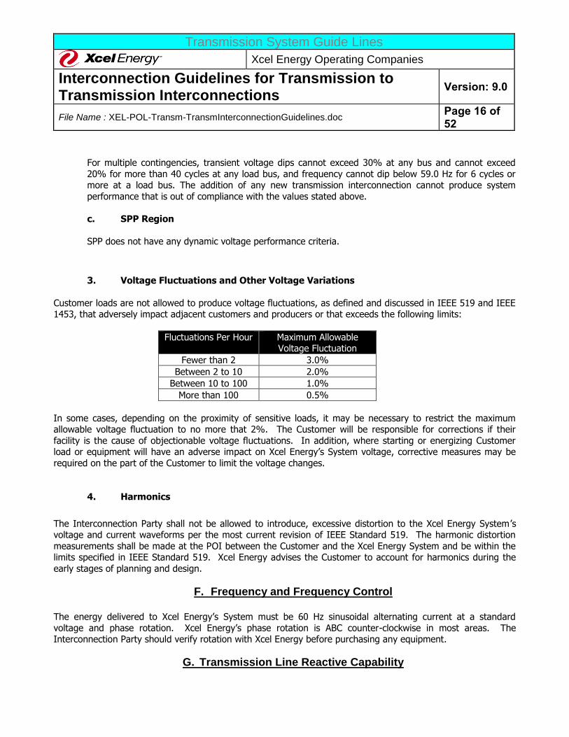
3. Voltage Fluctuations and Other Voltage Variations
Customer loads are not allowed to produce voltage fluctuations, as defined and discussed in IEEE 519 and IEEE 1453, that adversely impact adjacent customers and producers or that exceeds the following limits:
Fluctuations Per Hour Maximum Allowable Voltage Fluctuation
Fewer than 2 3.0%
Between 2 to 10 2.0%
Between 10 to 100 1.0%
More than 100 0.5%
In some cases, depending on the proximity of sensitive loads, it may be necessary to restrict the maximum allowable voltage fluctuation to no more that 2%. The Customer will be responsible for corrections if their
facility is the cause of objectionable voltage fluctuations. In addition, where starting or energizing Customer load or equipment will have an adverse impact on Xcel Energy’s System voltage, corrective measures may be
required on the part of the Customer to limit the voltage changes.
4. Harmonics
The Interconnection Party shall not be allowed to introduce, excessive distortion to the Xcel Energy System ’s voltage and current waveforms per the most current revision of IEEE Standard 519. The harmonic distortion
measurements shall be made at the POI between the Customer and the Xcel Energy System and be within the limits specified in IEEE Standard 519. Xcel Energy advises the Customer to account for harmonics during the
early stages of planning and design.
F. Frequency and Frequency Control The energy delivered to Xcel Energy’s System must be 60 Hz sinusoidal alternating current at a standard
voltage and phase rotation. Xcel Energy’s phase rotation is ABC counter-clockwise in most areas. The Interconnection Party should verify rotation with Xcel Energy before purchasing any equipment.
G. Transmission Line Reactive Capability

Transmission System Guide Lines
Xcel Energy Operating Companies
Interconnection Guidelines for Transmission to Transmission Interconnections
Version: 9.0
File Name : XEL-POL-Transm-TransmInterconnectionGuidelines.doc Page 17 of 52
All interconnections will be reactive compensated pursuant to good utility practice to ensure proper operation of
the interconnection. Interconnection Party must provide their own reactive support for their transmission facilities.
H. Fault Current Xcel Energy’s protective equipment fault current capability is based on the use of equipment with greater
capability than the maximum fault current available at a location. The Interconnection Party’s equipment capability must exceed the maximum fault current available. On the Xcel Energy System, this value may be over
63,000 amps. The exact value of available fault current depends upon location and circuit configuration and will be determined in the Facilities Study. The Interconnection Party must work closely with Xcel Energy at the time
of the interconnection design to determine the available fault current at the specific location of interconnection.
In addition this value may increase over time due to growth and changes in the interconnected power system. Therefore, the Interconnection Party should make accommodations for reasonable increases in fault current in
designing its Facility.
I. System Restoration and Black Start Capability
Under an extreme emergency, there may be a need for black start capability. The Xcel Energy Balancing Areas,
in conjunction with MRO, SPP, and WECC, have developed a process for restoring the Xcel Energy Balancing Areas and, by request, adjacent Balancing Areas. Xcel Energy may need to obtain more black start capability
from time to time.
J. Disconnect Device/Point of Demarcation
A disconnect device must be installed to isolate Xcel Energy’s System from the Interconnection Party’s. This disconnect shall be installed and owned by the Interconnection Party and shall provide a visible air gap and lock
to establish required clearances for maintenance and repair work of the Xcel Energy System. Xcel Energy does
not consider the integral switch available on some circuit-switchers as an acceptable way to meet this requirement. Xcel Energy may require the design to allow the application of personnel safety grounds on Xcel
Energy’s side of the disconnect device. OSHA lockout/tag requirements must be followed.
The disconnecting device must be accessible at all times to Xcel Energy personnel. The disconnects should
have the capability to be padlocked in the open position with a standard Xcel Energy padlock. The Interconnection Party shall not remove any padlocks or Xcel Energy safety or clearance tags. The
Interconnection Party must provide access to disconnect at all times (24 hours a day telephone number, guard desk, etc.). The disconnecting equipment must be clearly labeled. The disconnecting equipment shall be
approved for the specific application and location.
K. Effective Grounding
Xcel Energy maintains effective grounding on its transmission systems, as defined by IEEE 142. All Interconnection Party facilities connected to Xcel Energy’s System must be effectively grounded per the IEEE
142 requirement. These calculations should be made as if the Xcel Energy system was disconnected from the Interconnection Party (The Interconnection Party must meet the effective grounded system criterion
independent of the Xcel Energy system).
Transmission System Guide Lines
Xcel Energy Operating Companies
Interconnection Guidelines for Transmission to Transmission Interconnections
Version: 9.0
File Name : XEL-POL-Transm-TransmInterconnectionGuidelines.doc Page 18 of 52
IEEE 142 requires that: The positive sequence reactance is greater than the zero sequence resistance (X1 > R0); and the zero sequence reactance is less than three times the positive sequence reactance (X0 < 3X1).
Transmission System Guide Lines
Xcel Energy Operating Companies
Interconnection Guidelines for Transmission to Transmission Interconnections
Version: 9.0
File Name : XEL-POL-Transm-TransmInterconnectionGuidelines.doc Page 19 of 52
III. EQUIPMENT, PROTECTION AND CONTROL REQUIREMENTS This section indicates the minimum Xcel Energy design requirements for transmission facilities interconnecting
to the Xcel Energy transmission system. Any facilities constructed by the interconnection customer that will be
ultimately owned by Xcel Energy shall be designed using Xcel Energy substation and transmission design criteria and material standards, which will be made available upon request. The interconnecting party must
communicate and coordinate its system equipment, and protection and control designs and settings with the Xcel Energy engineering staff.
A. Fault Clearing
1. A fully rated circuit breaker is normally required to be installed at the PoI. Sync-check relay(s) must be
installed with the circuit breaker to ensure synchronous closing. Breaker failure relaying shall also be
included. Circuit breakers shall meet the latest applicable ANSI and IEEE standards and shall be suitable for the local environment and system operating conditions. Circuit breakers must be capable of
interrupting present and future available fault current at the location at which they are being installed. Fault currents will increase on the Xcel Energy system over time, the Interconnection Party needs to
periodically check fault levels to ensure their breaker meets these ever increasing values. It is
presumed that the installation meets the NEC/NESC certified by appropriate authorities to ensure safety of Xcel Energy personnel.
2. Application of ground-switches to trigger remote tripping is not an acceptable practice. Faults in the Interconnection Party’s network must not trip existing transmission lines as a primary protection
method. 3. The Interconnection Party must immediately and automatically isolate any faulted or failed equipment
from the Xcel Energy System. This automatic equipment must be compatible with the existing
transmission protection equipment.
Xcel Energy will require approval only for those portions of the Interconnection Party’s design that pertain directly to the protection of Xcel Energy System. Xcel Energy may make suggestions or comment on other
areas; however, the Interconnection Party is responsible for the design of protection schemes associated with
their transmission facilities.
B. Utility Grade Relays Utility grade protective and control relays are required for all transmission facilities interconnected to the Xcel
Energy System. The applicable relays are described in the next section (C. Minimum Protection Requirements) or as designated by the Facilities Study. The relays must:
1. Meet or exceed ANSI/IEEE Standards for protective relays (i.e., C37.90, C37.90.1, C37.90.2 and C37.90.3).
2. Have documentation covering application, testing, maintenance, and service. 3. Give positive indication of what caused a trip (Targets).
4. FT-1 switches are required to facilitate testing.
Transmission System Guide Lines
Xcel Energy Operating Companies
Interconnection Guidelines for Transmission to Transmission Interconnections
Version: 9.0
File Name : XEL-POL-Transm-TransmInterconnectionGuidelines.doc Page 20 of 52
The Interconnection Party is strongly encouraged to use microprocessor-based protective relays.
The self-diagnostic abilities, the sequence of events capabilities, and the increased flexibility of application are highly desirable. Xcel Energy may require that microprocessor style relays be
utilized for certain interface relay applications.
C. Minimum Protection Requirements
1. The following functions are required as a minimum to protect Xcel Energy’s equipment. The Facilities
Study will determine specific protective requirements.
a. Over-voltage (59). b. Under-voltage (27).
c. Over/Under Frequency (81O/81U).
d. Two zone Distance, Phase and Ground, (21). On short transmission lines current differential relay(s) may be substituted.
2. The following additional protection functions may be suggested or required depending upon the
nature of interconnection and coordination requirements with the Xcel Energy Protective Systems:
a. Breaker Failure
b. Out-of-Step (68). c. Transfer-Trip (TT).
d. Directional Overcurrent (67). e. Disturbance Recorder.
f. Power Quality Meter
D. Redundant/Backup Protection Relays protecting the Xcel Energy system shall be designed to ensure that the failure of a single protective relay
will not result in failure to clear the fault. Failure to trip during fault or abnormal system conditions due to relay or breaker hardware problems or from incorrect relay settings, improper control wiring, etc. is always a
possibility. The design shall provide the necessary backup that will meet the Xcel Energy standards and
regional protection requirements.
E. Synchronization Xcel Energy requires sync-check relays to be installed on all circuit breakers interconnecting the transmission
facilities to Xcel Energy’s transmission system. These relays, with additional voltage monitoring functions, will supervise the closing of the circuit breaker.
Manual closing of circuit breakers requires verification of synchronism using sync-scope to prevent out of synchronization closing. If this is also the point of generator synchronization, it is highly recommended to install
additional automatic synchronizing equipment.
Transmission System Guide Lines
Xcel Energy Operating Companies
Interconnection Guidelines for Transmission to Transmission Interconnections
Version: 9.0
File Name : XEL-POL-Transm-TransmInterconnectionGuidelines.doc Page 21 of 52
F. Station Power/Station Services
If the Interconnection Party does not provide for its own source of AC Station Power it must be provided externally. In this case, Station Power shall be provided for in accordance with NERC, regional ISO and/or local
state requirements. If the Interconnection Party is unable to provide its own Station Power, AC Station Power
may be provided by Xcel Energy.
However, it is possible that the Interconnection Party’s transmission facilities could be constructed in a location where it interconnects to an Xcel Energy transmission facility but Xcel Energy is not the local retail electric
provider. In this case the local retail provider will need to provide the AC Station Power.
If the Interconnection Party does provide for its own source of AC Station Power and is constructed such that it
is adjacent to the Xcel Energy facility, Xcel Energy may require AC Station Services for its facility be supplied from the Interconnection Party’s facility. In this case the Interconnection Party will be expected to match the
regional Station Service voltage in use by Xcel Energy. The three most common voltages are: 1) 120/240 VAC single phase, three wire; 2) 120/208 VAC three phase, four wire; and 3) 120/240 VAC three phase, four wire.
G. Grounding System
The Interconnection Party is responsible for the appropriate safety grounding of their equipment. At the point of
interconnection, the Interconnection Party’s grounding equipment must be compatible with Xcel Energy’s grounding equipment. The Interconnection Party shall submit the grounding system study and design for Xcel
Energy review prior to construction. The ground grid design must comply with IEEE 80 and properly address
site extremes. Site tests should be completed to determine soil resistivity prior to ground grid design. Xcel Energy grounding standards may be available upon request.
H. Communication Channel (s)
Xcel Energy may require that a communication channel and associated communication equipment be installed
as part of the protective scheme. This channel may consist of power line carrier, leased telephone line, pilot wire circuit, fiber optic cable, radio, or other means. Communication channels may be needed for telemetry,
SCADA, monitoring, relay/fault recorders, metering, or protection/control purposes. The Facilities Study will determine the specific communication channel requirements.
I. Metering and Telemetry
The interconnection shall require metering installed such that the delivery of power between the
Interconnection Party and Xcel Energy System can be determined. The metering installation shall be of billing
accuracy. The metering installation will be owned and maintained by Xcel Energy. The metering installation includes the CTs, VTs, meter, recorder, remote communication unit (usually a modem), and any auxiliaries
required. Xcel Energy may require in special circumstances, a readily available power quality meter (a.k.a. power quality monitor) be installed. Additional detail on revenue class metering and telemetry to the Xcel
Energy System Control Center is provided in Appendix B. Balancing area boundaries may require additional

Transmission System Guide Lines
Xcel Energy Operating Companies
Interconnection Guidelines for Transmission to Transmission Interconnections
Version: 9.0
File Name : XEL-POL-Transm-TransmInterconnectionGuidelines.doc Page 22 of 52
metering including, but not limited to a RTU, Dual-Port RTU, or Mini RTU for balancing area metering
Interchange.
J. Supervisory Control and Data Acquisition (SCADA)
Xcel Energy may require that the Interconnection Party substation(s) with a 69 kV or greater voltage circuit breaker provide remote control of the circuit breaker to the Xcel Energy Balancing Area operators. The
equipment data and statuses, which are to be provided, as applicable, include, but are not limited to what may be provided:
a. Breaker position.
b. Motor-operated disconnect position.
c. Bus voltage and alarming. d. Loss of AC and DC voltage alarms.
e. Transmission Line MW and MVar values and Amps. f. Lockout relay status.
g. Other control and data points as necessary to provide comparable control and indication to Xcel Energy
control standard. h. Digital Fault (Transient)/Dynamic recorder trouble alarm.
i. Protective Relay malfunction alarms. j. Energy accumulator or integrator.
k. Various alarms associated with substations
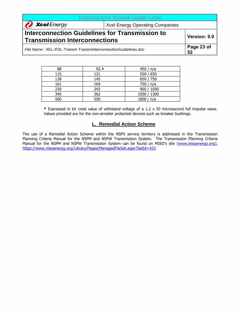
K. Voltage and BIL Values
The Interconnection Party must ensure that all equipment is adequately protected from excessive system over-voltages. This includes selection of equipment Basic Impulse Insulation Level (BIL) and protective devices (e.g.
surge arresters) to achieve proper insulation coordination. The addition of new transmission facilities to Xcel
Energy’s System in general should be modeled, and Transient Network Analysis (TNA) or Electromagnetic Transients Program (EMTP) studies may be required. The Facilities study will identify whether these detailed
studies are required. If so these studies should be completed before other major engineering work on the project commences. The following table indicates voltage and BIL levels found on most of the Xcel Energy
transmission system.
Voltage and BIL levels currently in use in TYPICAL Xcel Energy Substations:
NOMINAL
SYSTEM VOLTAGE
MAXIMUM
SYSTEM VOLTAGE
BASIC INSULATION
LEVELS (kV BIL, <2
km/>2 km)*
34.5 36.2 200 / 200
46 48.3 250 / 250
69 72.5 350 / 350
Transmission System Guide Lines
Xcel Energy Operating Companies
Interconnection Guidelines for Transmission to Transmission Interconnections
Version: 9.0
File Name : XEL-POL-Transm-TransmInterconnectionGuidelines.doc Page 23 of 52
88 92.4 450 / n/a
115 121 550 / 650
138 145 650 / 750
161 169 750 / n/a
230 242 900 / 1050
345 362 1050 / 1300
500 550 1800 / n/a
* Expressed in kV crest value of withstand voltage of a 1.2 x 50 microsecond full impulse wave. Values provided are for the non-arrester protected devices such as breaker bushings.
L. Remedial Action Scheme
The use of a Remedial Action Scheme within the NSPX service territory is addressed in the Transmission Planning Criteria Manual for the NSPM and NSPW Transmission System. The Transmission Planning Criteria
Manual for the NSPM and NSPW Transmission System can be found on MISO’s site (www.misoenergy.org), https://www.misoenergy.org/Library/Pages/ManagedFileSet.aspx?SetId=433
Transmission System Guide Lines
Xcel Energy Operating Companies
Interconnection Guidelines for Transmission to Transmission Interconnections
Version: 9.0
File Name : XEL-POL-Transm-TransmInterconnectionGuidelines.doc Page 24 of 52
IV. INTERCONNECTION PROCESS
A. Transmission Service Request
Note: As determined by FERC, a request for interconnection does not constitute a request for transmission service. The process described herein is not sufficient, nor intended to determine the capability of the
transmission network to supply the electric load power and energy requirements. In addition, a signed Interconnection Agreement does not provide the interconnection customer with any rights to transmission
service.
A customer desiring transmission service from Xcel Energy or the appropriate ISO must follow the procedures of
the Xcel Energy OATT or the ISO OATT in requesting transmission service.
B. Transmission to Transmission Interconnection Requests Steps 1. Interconnection Party provides a study to Xcel Energy documenting the need for interconnection,
alternatives, coordination with regional plans, and the detailed design of the facilities (e.g. breakers,
capacity needs, and timelines). If Interconnection Party can not provide a study, Xcel Energy will
perform a study at the Interconnection Party’s expense. Detailed design of the facilities includes, but is not limited to the following:
a. The interconnecting party is to identify their proposed point of interconnection and voltage level. (The ultimate point of interconnection and voltage level will be determined based on the
applicants study review or the Xcel Energy interconnection study. b. The requesting party must supply their proposed equipment ratings as required by Xcel Energy
to allow the establishment of the facility rating for the interconnecting facilities or as required
allowing appropriate system simulation modeling of the interconnecting facility. Final required facility ratings will be agreed to based on the results of the interconnection study.
c. The requester should identify in their interconnection request the MW demand levels expected on the interconnection facilities. Any MVAR compensation required for the
interconnecting facilities will be identified in the interconnection study
2. Xcel Energy will review and approve the study for the interconnection request or will identify issues and next steps to resolve the issues.
3. Upon resolution of the issues, if any, Xcel Energy and the Interconnection Party will work together towards the completion of the interconnection.
4. Prior to Xcel Energy initiating engineering, procurement, construction or installation of any facilities related to the interconnection of the applicant’s substation facilities to the system, an Interconnection
Agreement or Engineering and Procurement Agreement (E&P) must be executed between Xcel Energy
and the applicant. The Interconnection Agreement will define the terms and conditions under which Xcel Energy will construct the facilities to interconnect the new substation and, in some cases, will
upgrade portions of the transmission system. The Interconnection Agreement will also allocate the costs of the interconnection facilities, system upgrades between the applicant and Xcel Energy and
prescribe the design requirements for interconnection of the applicant’s substation facility. The E&P
agreement will allow Xcel Energy to begin any engineering or material procurement during the negotiation of the Interconnection Agreement if an expedited schedule is required. Once the
Transmission System Guide Lines
Xcel Energy Operating Companies
Interconnection Guidelines for Transmission to Transmission Interconnections
Version: 9.0
File Name : XEL-POL-Transm-TransmInterconnectionGuidelines.doc Page 25 of 52
Interconnection Agreement is executed, Xcel Energy will proceed with the interconnection process
and the Interconnection Agreement will be filed with the applicable regulatory agency. 5. Notification of new and modified facilities to others is addressed:
a. For NSP primarily through the MRO model building process and the MISO Transmission
Expansion Plan (MTEP) process. After a t-t interconnection is agreed to, if the two parties are MRO-Data Representative, they report their own facilities changes and model data to the
MRO in the MRO Model Building process. If the interconnecting party is not an MRO –DATA Representative, NSP will report and model their facilities. The process is similar for the MISO
annual MTEP process. b. For PSCo notification of new and modified facilities is accomplished through the Colorado
Coordinated Planning Group (CCPG) reporting process. Xcel Energy notifies the CCPG member
utilities of existing, new or planned projects and provides status reports to CCPG member utilities. CCPG is a joint, high voltage transmission system planning group that assures
reliability in the planning, development and operation of the high voltage transmission system in the Rocky Mountain Region. CCPG completes reliability assessments, develops joint business
opportunities, and accomplishes coordinated planning using a “single system” planning concept
that considers the Colorado utilities as one transmission entity for the purpose of meeting the transmission needs of the Colorado utilities in the most cost-effective way.
c. For SPS through the process outlined in Section 3.5 of the SPP Criteria. After all studies have been completed and reviewed by SPP’s Transmission Working Group, appropriate model
changes will be submitted by SPS and the interconnecting party to SPP directly through the
SPP model development process.
Current contact information for the three areas (NSPX- Minneapolis, PSCX – Denver, SPSX
– Amarillo) can be found on the Xcel Energy website (xcelenergy.com > Safety & Operation > Transmission > About Transmission > Interconnections for Transmission).
Transmission System Guide Lines
Xcel Energy Operating Companies
Interconnection Guidelines for Transmission to Transmission Interconnections
Version: 9.0
File Name : XEL-POL-Transm-TransmInterconnectionGuidelines.doc Page 26 of 52
V. ACCEPTANCE TESTING AND INSPECTION REQUIREMENTS Xcel Energy requires all Interconnection Parties proposing to interconnect to the Xcel Energy System be in
compliance with the applicable testing and/or performance requirements.
A. General
Prior to energizing the interconnection equipment with the Xcel Energy System, all pertinent contracts must be signed and all equipment modifications must be complete. The Interconnection Party is required to demonstrate
the correct operation of all interface protective and control devices to Xcel Energy. Xcel Energy shall define and witness, but is not responsible for performing this demonstration.
The Interconnection Party must provide detailed information on the protective relaying, metering, and control (including sync-check) equipment that will interface with the Xcel Energy System. This is usually provided on a
relaying and metering one-line (and possibly a three-line) diagram. Basic proposed AC and DC schematics or specification of logic may also be provided at this time. This information is required 90 days before the
Interconnection Party in-service date, along with a listing of the specific relays, etc., including information on the
manufacturer, model number, relay ranges, etc. Xcel Energy requires at least two sets of any design documentation packages sent. If any subsequent changes are made, the Interconnection Party shall provide Xcel
Energy a set of revised one-lines, schematics, construction drawings, etc. Based on this information, Xcel Energy will develop and deliver to the Interconnection Party the required demonstration test details within 30 days after
receipt of information from Interconnection Party. A coordination meeting shall be held with Xcel Energy and the Interconnection Party to clarify any questions that may exist before testing begins. The Interconnection Party is
also required to hold a coordination meeting with the Xcel Energy Transmission Control Center to establish a
specific switching sequence for the initial energizing of the Interconnection Facilities. The switching procedure will include a sign-off provision for the Interconnection Party.
Scheduling of demonstration testing should be coordinated through Xcel Energy with a minimum of three (3)
business days notice. All testing shall be completed at least seven (7) days prior to the planned in-service date
to provide time to resolve problems identified during testing. If no problems are identified then the equipment can be placed in service without delay. Based on the location and type of interconnection, Xcel Energy may, at
Xcel Energy’s sole discretion, require only a design and relay settings review and not require a site visit. The Interconnection Party shall be responsible for determining their own relay settings. At least sixty (60) days
before startup testing, the Interconnection Party must supply the proposed settings for the relays, including
support documentation (e.g. calculations, fault studies, time over-current relay coordination curves, etc.) for approval by Xcel Energy.
The Interconnection Party shall supply certified test reports for Xcel Energy’s required protective relaying,
interlocks, and any equipment directly connected to Xcel Energy’s System (Interconnection Party’s transformers and/or breakers). Certified test reports shall be sealed by a registered Professional Engineer (P.E.). Xcel Energy’s
personnel may require witnessing some or all of the tests, calibrations, and the relay setting applications. The final
“as-built” documentation for the interconnection facilities, including all drawings and final “as left” relay settings, must be provided by the Interconnection Party to Xcel Energy no later than 90 days after commercial operation
commences.
Xcel Energy document TCS-4 “Testing Criteria” provides the specific criteria that Xcel Energy uses for ensuring
its electrical equipment is properly tested and checked out. Xcel Energy requires that the Interconnection Party’s
Transmission System Guide Lines
Xcel Energy Operating Companies
Interconnection Guidelines for Transmission to Transmission Interconnections
Version: 9.0
File Name : XEL-POL-Transm-TransmInterconnectionGuidelines.doc Page 27 of 52
facilities that are an integral part of the Xcel Energy System, or may disrupt the Xcel Energy system due to
miss-operation or failure, must undergo a similar level of testing and checkout. The demonstration testing indicated above is employed to ensure that the Interconnection Party has completed the appropriate testing and
checkout. Specific regional requirements may apply and may be obtained from the regional Xcel Energy
representative by request.
The Interconnection Party must assign one qualified and proficient protection and controls person to be the main point of contact throughout the commissioning phase of the project. This person should have adequate
field experience in protection and control of high-voltage equipment as appropriate to the system they are working on. This person’s experience should include, but not be limited to polarity checks, phase-outs, relay
calibration, and trip testing for multiple large projects. This person will also insure adherence to these
Guidelines. The Interconnection Party must also provide qualified electricians, technicians, and operators to perform the demonstration testing. The Interconnection Party must supply all personal protective equipment
and designate any procedures necessary to assure that safety precautions are taken while working near energized equipment.
Inspection and approval by Xcel Energy does not constitute a warranty or relieve the Interconnection Party of responsibility for the operating condition or installation of the equipment, and may not be relied upon by the
Interconnection Party for that purpose. Once the facility is interconnected, Xcel Energy will retain the right to inspect the facility if the operation is suspected of causing problems for other Xcel Energy facilities or customers
and retains the right to inspect the facilities of the Interconnection Party at Xcel Energy’s discretion.
B. Demonstration
The Interconnection Party and Xcel Energy shall follow the following steps in assuring that the new facilities have been adequately tested prior to energization.
1. Construction Testing Documentation Review
The Interconnection Party must complete field-testing of all their electrical equipment prior to
commissioning and energization. This includes physical testing of equipment such as transformers and circuit breakers per the manufacturers’ recommendations. This testing also includes setting and testing of
relays and control systems per the manufacturers’ recommendations, as well as verifying Xcel Energy approved relay settings. The extent of testing shall be consistent with the level of testing specified in the
International Electrical Testing Association (NETA) or National Institute for Certification in Engineering
Technologies (NICET) and good utility practice. These tests shall be completed prior to demonstration testing as outlined in the following paragraph. Xcel Energy may require being a witness to some of these
testing activities. Xcel Energy will notify the Interconnection Party prior to the start of testing if witness testing is required. In some cases, review of these test reports shall constitute sufficient demonstration that
proper testing has been completed.
The Interconnection Party must submit reports for all tests performed for approval by Xcel Energy. All
revisions and changes found on field drawings shall be shown on the Interconnection Party drawing and copies provided to Xcel Energy for approval by Xcel Energy. A written record must be kept of all tests
showing date, personnel performing test, signature or initial of person completing tests, equipment or
Transmission System Guide Lines
Xcel Energy Operating Companies
Interconnection Guidelines for Transmission to Transmission Interconnections
Version: 9.0
File Name : XEL-POL-Transm-TransmInterconnectionGuidelines.doc Page 28 of 52
material tested, as-left results, and type of testing equipment used by manufacturer, model type, and model
serial number. The test sheets must show all equipment nameplate data (including for all bushings and surge arresters).
The requirements in this paragraph apply to equipment that will be owned by Xcel Energy. Two copies of the final test reports must be submitted. Three copies of application software and instruction books are to
be supplied to Xcel Energy along with the test reports.
The Interconnection Party must download settings and programs from each relay and programmable logic controller after testing to retrieve all as-left-in-service settings, and shall copy these files onto a CD-ROM, or
e-mail the data to Xcel Energy. For non-microprocessor-based relays, test sheets or reports for each device
are to be completely filled out. All relay setting sheets are to be checked against as-left settings on the corresponding relay device and signed as being complete by the responsible technical person. The CD-
ROM, test sheets, reports, and settings are to be labeled with equipment identification numbers, relay type numbers, and relay device numbers and returned to Xcel Energy with the test reports. The address is
provided in Section II of these Guidelines.
2. Demonstration Tests
Demonstration tests must be employed to ensure that each of the required protection systems and protective devices operate correctly. These tests are used to verify that the Interconnection Party has
completed testing as indicated in the preceding paragraph. These tests also verify synchronizing equipment and the proper operation of the Xcel Energy – Interconnection Party interface protective relays. Xcel Energy
will produce the demonstration test requirements and deliver them to the Interconnection Party. Upon
performance and certification of the Demonstration, the Interconnection Party will be granted approval for operation of their transmission facilities in parallel with Xcel Energy’s System. Unsuccessful demonstration
may lead to delays in the Interconnection Party facility in-service date. Xcel Energy and the Interconnection Party will develop an initial energization procedure at least two weeks prior to energization. If deemed
necessary by Xcel Energy, a meeting will be held on site within one week of the energization date to discuss
any particulars of the initial energization.
The actual demonstration requirements will depend upon the final, approved AC/DC schematics, relay settings, etc. This demonstration is intended to be non-destructive. However, Xcel Energy will not be liable
for any equipment damage or injury resulting from the use of these guidelines. It is the responsibility of
the Interconnection Party to demonstrate the operation of all protective devices in a safe manner and in a manner that does not adversely affect the Interconnection Party or any equipment on the Xcel Energy
System. Xcel Energy recommends that similar tests be performed for the Interconnection Party’s other relays to insure the adequacy of all protective relaying.
3. Post In-Service Tests
These tests are employed for verification of correct relay connections under actual load conditions. This is
commonly known as “load checking”. These checks are completed by directly measuring actual operating
quantities in differential, distance, and overcurrent relays. This also includes spot-checking of metering and
Transmission System Guide Lines
Xcel Energy Operating Companies
Interconnection Guidelines for Transmission to Transmission Interconnections
Version: 9.0
File Name : XEL-POL-Transm-TransmInterconnectionGuidelines.doc Page 29 of 52
SCADA systems. Post in-service tests may also include online tests of substation equipment including
insulating oil tests of power transformers and infrared-thermography testing.
C. Future Changes In Requirements
From time to time new requirements for testing, reporting, equipment and/or performance are established by
MRO, SPP, WECC, NERC, etc., for interconnections. The Interconnection Party should take steps so it is notified of any changes by the applicable entity. If an Interconnection Party fails to comply with these requirements
and Xcel Energy is required to pay monetary penalties assessed to Xcel Energy as the Balancing Authority entity responsible for regional interconnected system reliability. Xcel Energy will bill the Interconnection Party for any
monetary penalty resulting from the non-performance of the Interconnection Party.
D. Performance of Tests
The Interconnection Party must test all wire, cable, electrical equipment, and systems installed by the Interconnection Party or connected by the Interconnection Party to assure proper installation, adjustment,
setting, connection, and functioning. The Interconnection Party must inform Xcel Energy of any equipment or system that fails testing or that is deficient in any matter. The extent of testing where modifications are made
to existing circuits shall be sufficient to check the entire trip/control/CT/VT path as if it were new. Xcel Energy
will not be responsible for any damage to equipment or material due to Interconnection Party’s inadequate, substandard, improper test procedures or test apparatus handling.
Xcel Energy reserves the option to assign its personnel to assist the Interconnection Party in checking out
certain control schemes where Xcel Energy concludes such assistance is necessary to meet the project schedule. If Xcel Energy should exercise this option, the Interconnection Party will be notified in advance of the
extent of Xcel Energy's involvement.
Xcel Energy also reserves the right to shut down testing activities if, in Xcel Energy's opinion or the opinion of
Xcel Energy's designated representative, the Interconnection Party is using unsafe practices or is in violation of applicable local, state, or federal safety regulations. Xcel Energy requires compliance with the most
conservative of the safety practices as provided by OSHA, NESC, or Xcel Energy's safety practices whenever
work is being performed in an energized facility.
E. Testing Equipment The Interconnection Party must provide all equipment necessary to perform the tests required by Xcel Energy. A
list of testing equipment shall be submitted to Xcel Energy for approval prior to the beginning of the testing.
Test instrument type (manufacturer, type, serial number) and associated calibration certifications shall be submitted to Xcel Energy prior to the commencement of any testing. The equipment certification shall be
renewed at least annually and shall be traceable to the National Bureau of Standards. Xcel Energy will review the list and notify the Interconnection Party of any testing items that are not acceptable or are missing from the
list. The Interconnection Party shall correct this deficiency prior to the start of testing.
Transmission System Guide Lines
Xcel Energy Operating Companies
Interconnection Guidelines for Transmission to Transmission Interconnections
Version: 9.0
File Name : XEL-POL-Transm-TransmInterconnectionGuidelines.doc Page 30 of 52
F. Xcel Energy Supplied Equipment
Any Xcel Energy supplied equipment that is factory calibrated (transducers, pressure switches, tuners, etc.) shall be tested to verify calibration. The Interconnection Party may not modify calibration settings without
authorization from Xcel Energy. If equipment does not meet specifications, the Interconnection Party should
notify Xcel Energy of the problem immediately. Xcel Energy will then direct the Interconnection Party on how to proceed. If the Interconnection Party modifies factory settings without authorization, Xcel Energy will not be
responsible for any costs associated with repair, replacement, or re-calibration of the Interconnection Party’s transmission facilities.
G. Final Design/As-Built Documents
The Interconnection Party must at the time of demonstration testing have a complete set of construction
drawings and documentation available. These documents should represent a complete set of information showing exactly how the facility has been built and the logic behind how the control systems will operate. The
documents shall include but are not limited to one-line diagrams, meter and relaying diagrams (M&R), AC and DC elementary diagrams (schematic drawings), circuit lists, Programmable Logic Controller (PLC) and relay
logic, and any other appropriate or necessary information. Xcel Energy should be provided a duplicate copy of
this documentation at least two weeks prior to demonstration testing. A coordination meeting with Xcel Energy should be held to clarify any questions on documentation or testing requirements before demonstration testing
begins.
Transmission System Guide Lines
Xcel Energy Operating Companies
Interconnection Guidelines for Transmission to Transmission Interconnections
Version: 9.0
File Name : XEL-POL-Transm-TransmInterconnectionGuidelines.doc Page 31 of 52
VI. OPERATION AND MAINTENANCE GUIDELINES
General guidelines will be stated below, but any specific guidelines will be defined in the Interconnection
Agreement between the Xcel Energy operating companies and the Interconnection Party.
The Interconnection Party shall operate within the applicable guidelines of this document and any other specific requirements as stated in the Interconnect Agreement, the Power Purchase Agreement, the Transmission
Service Agreement, or the Ancillary Services Agreement, if applicable.
A. Normal Conditions The Interconnection Party must operate according to the instructions and approval given by the Xcel Energy
Transmission Control Center personnel:
1. The Interconnection Party has twenty-four hour support available.
B. Abnormal Conditions Xcel Energy reserves the right to open the interconnection for any of the following reasons:
1. Xcel Energy line maintenance work on Xcel Energy System.
2. Xcel Energy substation maintenance on Xcel Energy System.
3. Xcel Energy System emergency. 4. Inspection of a Interconnection Party's substation equipment and protective equipment reveals a
hazardous condition. 5. Failure of the Interconnection Party to provide maintenance and testing reports when required.
6. Interconnection Party's transmission facilities interfere with other Xcel Energy customers, other
Interconnection Parties, or with the operation of Xcel Energy’s System. 7. Interconnection Party has modified the transmission facilities that affect Xcel equipment without the
knowledge and approval of Xcel Energy or has not installed Xcel required protective devices. 8. Personnel or public safety are threatened.
9. Interconnection Party fails to comply with applicable OSHA Safety Tagging and Lockout
requirements.
Changes to the Xcel Energy System or the addition of other Interconnection Party’s facilities, loads, or
generators in the vicinity may require modifications to the interconnection protective devices. If such changes are required, the Interconnection Party may be subject to future charges for these modifications.
C. Energization of Xcel Energy Equipment by the Interconnection Party The Interconnection Party must not energize a de-energized Xcel Energy circuit (unless specifically authorized
and requested by Xcel Energy).
Transmission System Guide Lines
Xcel Energy Operating Companies
Interconnection Guidelines for Transmission to Transmission Interconnections
Version: 9.0
File Name : XEL-POL-Transm-TransmInterconnectionGuidelines.doc Page 32 of 52
D. Maintenance Notification
The Interconnection Party must notify Xcel Energy or the ISO as provided for in the applicable OATT of any unusual conditions including, but not limited to the following:
1. Partial operating capability due equipment limitations. 2. Scheduled outage periods and return to service expectations. Return to service notification must be
updated daily to reflect the recent progress or the lack of progress.
E. Maintenance
Interconnection protective devices owned by the Interconnection Party should be maintained and inspected according to manufacturer recommendations, NERC, and/or industry standards. Procedures must be
established for visual and operational inspections. Provisions should be established for equipment maintenance and testing. Equipment should include, but not be limited to:
1. Power Transformers 2. Circuit Breakers
3. Protective Relays 4. Station Batteries
5. Instrument transformers
6. Communication equipment (including channels)
Xcel Energy maintains the right to review the maintenance, calibration, and operation data of all protective equipment for protecting Xcel Energy facilities, customers, and other producers. The Interconnection Party is
responsible for providing the necessary test accessories (such as relay test plugs, instruction manuals, wiring diagrams, etc.) required to test these protective devices. Verification testing may include the tripping of the
intertie breaker. If Xcel Energy performs work on the premises of the Interconnection Party, Xcel Energy
operating personnel may make an inspection of the work area. If hazardous working conditions are detected, the Interconnection Party must correct the unsafe conditions before Xcel Energy personnel will perform their
work.
F. Design Changes After Commercial Operation
Any modifications to the Interconnection Party requiring Xcel Energy protective relaying and interlocks after the date of commercial operation must be reviewed and approved by Xcel Energy prior to implementing any
changes. Demonstration of Relay Calibration, Trip Tests, and On-Line Tests may be required depending on the extent of the design change. Setting changes of any interconnection protection or synchronizing device must
be approved by Xcel Energy with a hard copy of the changes forwarded to the designated Xcel Energy
representative. Any "Field Modification" or "As Built" AC/DC protection and synchronizing schematics associated with any Xcel Energy required interconnection device must be forwarded to the designated Xcel Energy
representative.
Transmission System Guide Lines
Xcel Energy Operating Companies
Interconnection Guidelines for Transmission to Transmission Interconnections
Version: 9.0
File Name : XEL-POL-Transm-TransmInterconnectionGuidelines.doc Page 33 of 52
G. Operating Data Submittals
The Interconnection Party must provide operating data and equipment modeling to Xcel Energy and/or the appropriate regional reliability organization to support the following:
1. NERC compliance program(s).
2. Regional Reliability Organization compliance program(s).
3. Federal, state and local regulatory programs.
H. Operational Log Interconnection Party must maintain an operating log at each interconnection facility indicating changes in
operating status, maintenance outages, trip indications, or other unusual conditions found upon inspection.
I. Communication With Xcel Energy Operations
The Xcel Energy representative will provide the Interconnection Party with the names and telephone numbers of the Xcel Energy Control Center and Operations Coordination personnel responsible for Xcel Energy System at
the interconnection. The Interconnection Party will provide Xcel Energy with the names and telephone numbers of the personnel with responsibility for operating the interconnection Facilities.
The contact(s) of the Interconnection Party should include at least one 24/7-telephone number. Contacts should be able to provide information on equipment status, explanation of events on the Interconnection Party’s
transmission facilities, and relay target and alarm information when asked to do so by Xcel Energy personnel. In addition, the Interconnection Party should contact Xcel Energy whenever:
1. Problems with the Interconnection are detected that could result in mis-operation of interconnection
protection or other interconnection equipment.
2. The Interconnection has opened by protective relay action. 3. Interconnection transmission facility’s problems result in an outage to a portion of the Xcel Energy
System. 4. The Interconnection Party intends to initiate switching to parallel the Interconnection Party(s) and the
Xcel Energy System.
5. The Interconnection Party intends to initiate switching to break the parallel interconnection between Interconnection Party(s) and the Xcel Energy System.
Transmission System Guide Lines
Xcel Energy Operating Companies
Interconnection Guidelines for Transmission to Transmission Interconnections
Version: 9.0
File Name : XEL-POL-Transm-TransmInterconnectionGuidelines.doc Page 34 of 52
VII. GLOSSARY AGC (Automatic Generation Control): An EMS based system that sends raise and lower instructions to the
governors of the generators in the Balancing Authority for the purpose of matching the generation output to the
area load. This is also known as Load Frequency Control (LFC).
Alternating Current (AC): That form of electric current that alternates or changes in magnitude and polarity (direction) in a regular pattern for a given time period.
Ampere: The unit of current flow of electricity. It is to electricity as the number of gallons per minute is to the
flow of water. One-ampere (A) flow of current is equal to one coulomb per second flow.
ANSI: American National Standards Institute.
Apparent Power: For single-phase power, the current in amperes multiplied by the voltage equals the
apparent power in volt-amperes (VA). Apparent power for 3-phase power equals the phase to neutral voltage
multiplied by the line current multiplied by 3.
ATP (Alternate Transients Program): A digital computer modeling program that is typically utilized for performing high frequency lightning and/or switching induced transient power system studies. This is similar to
EMTP and is not supported by the Electric Power Research Institute (EPRI).
Automatic: Self-acting, operated by its own mechanism when actuated by some impersonal influence as, for
example, a change in current strength; not manual; without personal intervention.
Automatic Reclosing: A circuit breaker has automatic reclosing when means are provided for closing without manual intervention after it has tripped under abnormal conditions.
Balancing Area: A balance area is an electrical system bound by interconnect (tie-line) metering and telemetry and which regulates its generation in order to maintain its interchange schedule with other systems, contributes
to frequency regulation of the Interconnection, and fulfills its obligations and responsibilities in accordance with NERC and reliability region (such as MRO, SPP, or WECC) requirements.
Balancing Area Operator: An individual charged with the operation of a balance area.
Capacity: The number of amperes of electric current a wire will carry without becoming unduly heated; the maximum ability of a machine, apparatus, or device under existing service conditions; the load for which a
transformer, transmission circuit, apparatus, station, or system is rated.
Circuit: A conducting path through which an electric current is intended to flow.
Circuit Breaker: A device for interrupting a circuit between separable contacts under normal or fault
conditions. The interrupting ability of the device is normally rated or sized such that it exceeds the maximum fault current that is available at the location of application.
CT (Current Transformer): A transformer intended for metering, protective, or control purposes and which is designed to have its primary winding connected in series with a circuit carrying the current to be measured or
Transmission System Guide Lines
Xcel Energy Operating Companies
Interconnection Guidelines for Transmission to Transmission Interconnections
Version: 9.0
File Name : XEL-POL-Transm-TransmInterconnectionGuidelines.doc Page 35 of 52
controlled. A current transformer normally reduces current magnitudes to levels which can be handled by
control, protection, and metering equipment. A CT secondary circuit must never be open-circuited while energized.
Current: A flow of electric charge measured in amperes (A).
Demand: The rate at which electric power is delivered to or by a system; normally expressed in kilowatts (kW), megawatts (MW), or kilovolt-amperes (kVA).
Disconnect: A device used to isolate a piece of equipment and which has a minimal ability or no ability to
interrupt current. A disconnect may be gang-operated (all poles switched simultaneously) or individually
operated.
Dynamic Voltage Excursion: Transient change in system voltage magnitude, typically associated with a condition following clearing a system short-circuit or fault.
EMS (Energy Management System): The computer system Xcel Energy uses to provide real-time status and remote control of its electrical transmission system.
EMTP (Electromagnetic Transients Program): A digital computer modeling program that permits the
analysis of the transient behavior of electrical networks. This program is presently supported by Electric Power
Research Institute (EPRI).
Energy Losses: The general term applied to energy lost in the operation of an electrical system. Losses can be classified as Transformation Losses, Transmission Line Losses, or System Losses.
ERO (Electric Reliability Organization): The FERC designated electric reliability organization formed as
prescribed in the Energy Policy Act of 2005. NERC is the current ERO. NERC has established reliability
standards, and provide for enforcement of those standards.
Facilities Study: A study conducted by the Transmission Provider or a qualified third party consultant for the Interconnection Party which is reviewed and approved by Transmission Provider to determine a list of facilities,
the cost of those facilities, and the time required to interconnect the Generating Facility with the Transmission
Provider’s Transmission System.
FERC (Federal Energy Regulatory Commission): (Formerly the Federal Power Commission, or FPC.) FERC is an independent body within the Department of Energy (DOE) regulating interstate transmission and the
prices of electricity and natural gas. It also licenses hydroelectric projects and regulates interconnections, construction work in progress, rates for wholesale Producers, utility accounting practices, and procedures.
Frequency: The number of alternating cycles occurring in a given interval of time (usually one second) in an electric current or voltage. Frequency is commonly expressed in hertz (Hz).
Fuse: A short piece of conducting material of low melting point, which is inserted in a circuit for the purpose of
opening the circuit when the current reaches a certain value.
Transmission System Guide Lines
Xcel Energy Operating Companies
Interconnection Guidelines for Transmission to Transmission Interconnections
Version: 9.0
File Name : XEL-POL-Transm-TransmInterconnectionGuidelines.doc Page 36 of 52
Ground: A term used in electrical work in referring to the earth as the zero potential conductor or reference
plane. For safety purposes, circuits are grounded while any work is being done on or near a circuit or piece of equipment in the circuit. This is usually called protective or safety grounding.
Hertz (Hz): The term denoting frequency. Historically, frequency was referred to as cycles per second.
IEEE: Institute of Electrical and Electronics Engineers, Inc.
Interconnection Facilities: The facilities required to make the physical connection between the Producer’s generation facility and the Xcel Energy transmission system. This may include new substation and transmission
facilities as well as other system upgrades to be owned by Xcel Energy.
Interruption: A temporary discontinuance of the supply of electric power.
Interconnection Party: Party requesting to interconnect with the Xcel Energy Transmission System.
IPP (Independent Power Producer): An organization that is not a utility and that operates a power plant that produces energy and sells it to a utility.
Island: A part of an interconnected system that may become isolated from the rest of the system during a
system disturbance and start operating as a subsystem with its own generation, transmission, and distribution
capability. The islanded system and the main interconnected system may operate at different frequencies and voltages.
ISO (Independent System Operator): Entities corporately separate from the owners of transmission and
other power market participants approved by FERC to direct the operation of the transmission system.
ITC (Independent Transmission Company): Entities corporately separate from the owners of transmission
and other power market participants approved by FERC to direct the operation of the transmission system.
Kilovolt (kV): One thousand volts.
Kilovolt-Ampere (kVA): One thousand-volt ampere. See the definition for Apparent Power.
Kilowatt (kW): An electric unit of power that equals 1,000 Watts.
Lagging Power Factor: Occurs when reactive power flows in the same direction as real power.
Leading Power Factor: Occurs when reactive power flows in the opposite direction of real power.
Line Losses: Electrical energy converted to heat in the resistance of all transmission and/or distribution lines and other electrical equipment.
MISO (Midcontinent Independent System Operator): A FERC-approved ISO corporately independent of
Xcel Energy and to whom Xcel Energy has turned over the operations authority of its transmission system. The
Transmission System Guide Lines
Xcel Energy Operating Companies
Interconnection Guidelines for Transmission to Transmission Interconnections
Version: 9.0
File Name : XEL-POL-Transm-TransmInterconnectionGuidelines.doc Page 37 of 52
MISO will operate much of the transmission system from Minnesota, Wisconsin, Iowa, Illinois, Pennsylvania,
Kentucky, and Missouri.
Megavolt-Ampere (MVA): One million-volt ampere. See definition for Apparent Power.
Megawatt (MW): An electrical unit of power that equals one million watts.
MRO (Midwest Reliability Organization): A NERC Regional Entity operating in one NERC reliability region.
NERC (North American Electric Reliability Corporation): NERC is the Electric Reliability Organization
responsible for establishing and enforcing the Reliability Standards to assure the reliability of the NERC defined
Bulk Electric System. NERC has delegated certain authority for Reliability Standard Enforcement to the Regional Entities in the NERC Reliability Regions (SPP, WECC, and MRO).
OATT (Open Access Transmission Tariff): The FERC approved tariff for provision of transmission service to
the Producer.
On-Line Testing: Testing typically performed as part of commissioning a new generation facility, specifically as
it pertains to energized equipment ultimately operating in parallel / interconnected with the power system.
One-Line Diagram: A diagram in which several conductors are represented by a single line and in which
various devices or pieces of equipment are denoted by simplified symbols. The purpose of such a diagram is to present an electrical circuit or circuits in a simple way so that their function can be readily grasped.
Parallel Operation: The operation of a Producer-owned generator while connected to the utility's grid.
Parallel operation may be required solely for the operating convenience of the customer or producer, or for the intentional interchange of power with the utility's grid.
Peak Load: The maximum electric power consumed in a stated period.
Point of Change of Ownership (PoCO): The point where the Producer’s Interconnection Facilities connect to Xcel Energy’s Interconnection Facilities.
Point of Energy Exchange: The point in the delivery system where one party takes delivery of the energy from the other party. This point is defined in the contract between Xcel Energy and the Producer. It is usually
the point where facility ownership changes. For transmission-connected Producers, this is usually at a location at the transmission voltage level. This is often referred to as the PoI or PoD.
Point of Interchange: See Point of Energy Exchange.
Point of Interconnection (PoI): The point where the Interconnection Facilities connect to the Transmission Provider's Transmission System.
Power (Actual, Active, or Real Power): The time rate of transferring or transforming energy or the power
that accomplishes work, measured in Watts.
Transmission System Guide Lines
Xcel Energy Operating Companies
Interconnection Guidelines for Transmission to Transmission Interconnections
Version: 9.0
File Name : XEL-POL-Transm-TransmInterconnectionGuidelines.doc Page 38 of 52
Power Factor (PF): The ratio of actual power (kW) to apparent power (kVA).
Power Flow: One-way power flow is the condition where the flow of power is entirely into or out of the facility
of the Producer. Two-way power flow is the condition where the net flow of power may be either into or out of
the facility depending on the operation of the generator and other Producer load.
Professional Engineer (P.E.): A licensed professional engineer registered with the appropriate state agency.
Programmable Logic Controller (PLC): A special form of micro-processor based controller that uses a programmable memory too store instructions (“ladder logic”), and to implement functions such as logic
sequencing, timing, and arithmetic in order to control machines and processes.
Protection: All of the relays and other equipment that are used to open the necessary circuit breakers and
fuses to automatically clear or disconnect lines or equipment when trouble develops.
PSCAD - is a simulation program similar to EMTP and ATP programs. PSCAD is a registered trade mark of
Manitoba HVDC research center Inc.
Reactive Power (var): The power that oscillates back and forth between inductive and capacitive circuit elements without ever being used. The function of reactive power is to establish and sustain the electric and
magnetic fields that are required to perform useful work in AC systems.
Relay: A device that is operated by a variation in the condition of one electric circuit to affect the operation of
another device in the same or in another electric circuit.
Remote Terminal Unit (RTU): A device installed at a substation or generation facility, and at an XE Operations Control Center, and is used to provide communication for remote control and indication of substation
or generation facility equipment from the XE Operations Control Center.
Regional Entities (RE): Expected to replace the RRO after the implementation of the Electric Reliability
Organization.
RRO (Regional Reliability Organization): The entity under the authority of NERC responsible for the
reliable operation and use of the electric power system within a specific geographic region.
RTO (Regional Transmission Operator): Entities corporately separate from the owners of transmission and other power market participants approved by FERC to independently direct the operation of the transmission
system.
SPP (Southwest Power Pool): SPP Operates both an RTO and a RE. The SPP RTO performs the
independent transmission functions required of that entity while the SPP RE is the NERC delegated authority in the SPP Reliability Region for the enforcement of NERC Reliability Standards. These two entities are distinctly
separate with different governance structures and personnel. The SPP RTO has a Pool-Wide Tariff under which Xcel Energy has placed the SPS operating area. This tariff governs generator interconnection requests and
provides network and point-to-point transmission service. SPP Operates in portions of Texas, New Mexico,
Oklahoma, Kansas, Nebraska, Missouri, Arkansas, and Louisiana.
Transmission System Guide Lines
Xcel Energy Operating Companies
Interconnection Guidelines for Transmission to Transmission Interconnections
Version: 9.0
File Name : XEL-POL-Transm-TransmInterconnectionGuidelines.doc Page 39 of 52
Station Power: The electric power used for the heating, lighting, air-conditioning and office equipment needs of the buildings on a Generation Facility’s site, and for operating the electric equipment that is on the
Generating Facility’s site.
Station Service: The electric energy needs of the Transmission Provider’s substation equipment.
Switch: A device for making, breaking, or changing the connections in an electric circuit.
System: The entire generating, transmitting, and distributing facilities of an electric system.
Transformer: An electric device, without continuously moving parts, in which electromagnetic induction transforms electric energy from one circuit to one or more other circuits at the same frequency, usually with
changes in the magnitudes of the voltage and current.
Transient Network Analysis (TNA): A digital computer modeling program that permits the analysis of the
transient behavior of electrical networks.
Transmission Owner: An entity that owns leases or otherwise possesses an interest in the portion of the Transmission System at the Point of Interconnection and may be a Party to the Interconnection Agreement to
the extent necessary.
Transmission Provider: The public utility (or its designated agent) that owns, controls, or operates
transmission or distribution facilities used for the transmission of electricity in interstate commerce and provides transmission service under the OATT. The Transmission Provider includes the Transmission Owner when the
Transmission Owner is separate from the Transmission Provider.
Utility Grade Relays: Relays that meet IEEE C37.90, C37.90.1, C37.90.2, and C37.90.3.
var: Volt-ampere reactive, see Reactive Power.
var Capability Testing: Testing performed with a generation facility interconnected with the XE power system
in order to verify or determine the generation facility's net reactive power (var) output and corresponding power
factor, typically as measured at the PoI.
Voltage: Electric potential or potential difference expressed in volts (V).
Volt-Ampere: A unit of apparent power (VA) in an alternating-current circuit.
VT (Voltage Transformer): A transformer intended for metering, protective, or control purposes and which is
designed to have its primary winding connected either between the primary conductors to be measured or between a conductor and ground. A voltage transformer normally reduces voltage magnitudes to levels which
can be handled by control, protection, and metering equipment. The historic term for a VT is potential transformer.
Watt-Hour: A unit of work or energy equivalent to the power of one Watt operating for one hour (Wh).
Transmission System Guide Lines
Xcel Energy Operating Companies
Interconnection Guidelines for Transmission to Transmission Interconnections
Version: 9.0
File Name : XEL-POL-Transm-TransmInterconnectionGuidelines.doc Page 40 of 52
WECC (Western Electric Coordination Council): a NERC Regional Entity operating in the Western Grid reliability region. WECC serves both as an organization of power suppliers in the Western States that plans for
power availability by coordinating power exchanges between members and as a NERC delegated Regional Entity
responsible for the development of regional reliability standards and for the Enforcement of NERC Reliability Standards and its own regional standards. WECC’s current members include investor-owned companies such as
Xcel Energy, municipal systems, rural cooperatives, the Western Area Power Administration, Bonneville Power Administration, and the US Bureau of Reclamation. All operating in the Western Interconnection.
Wye or "Y" Connected Circuit (Star Connected): A three-phase circuit in which windings of all three
phases have one common neutral point connection.
Transmission System Guide Lines
Xcel Energy Operating Companies
Interconnection Guidelines for Transmission to Transmission Interconnections
Version: 9.0
File Name : XEL-POL-Transm-TransmInterconnectionGuidelines.doc Page 41 of 52
VIII. REFERENCES The following list of references has been utilized in preparation of this document and/or should be consulted for
further information/clarification. When the following publications/standards are superseded by an approved
revision, the latest revision shall apply.
ANSI C2-2002, National Electrical Safety Code.
ANSI C84.1-1995 (R2005), Electric Power Systems and Equipment - Voltage Ratings (60HZ).
IEEE Std. C37.106TM –2003, IEEE Guide for Abnormal Frequency Protection for Power Generating Plants,
ANSI/ IEEE C37.90-1989, IEEE Standard for Relays and Relay Systems Associated with Electric Power
Apparatus.
IEEE Std C37.90.1-2002TM – 2002, IEEE Standard for Surge Withstand Capability (SWC) Tests for Relays and
Relay Systems Associated with Electric Power Apparatus.
IEEE Std C37.90.2TM-2004, IEEE Standard for Withstand Capability of Relay Systems to Radiated Electromagnetic Interference from Transceivers.
IEEE Std C37.90.3-2001, IEEE Standard Electrostatic Discharge Tests for Protective Relays.
IEEE Std C37.95TM – 2002, IEEE Guide for Protective Relaying of Utility-Consumer Interconnections.
IEEE Std 80-2000, IEEE Guide for Safety in AC Substation Grounding.
IEEE Std-142-1991, IEEE Recommended Practice for Grounding of Industrial and Commercial Power Systems –
IEEE Green Book (Color Book Series).
IEEE Std-242-2001, IEEE Recommended Practice for Protection and Coordination of Industrial and Commercial Power Systems – IEEE Buff Book (Color Book Series).
IEEE Std-446-1995, IEEE Recommended Practice for Emergency and Standby Power Systems for Industrial and Commercial Applications – IEEE Orange Book (Color Book Series).
IEEE 519-1992, IEEE Recommended Practices and Requirements for Harmonic Control in Electrical Power
Systems.
IEEE 1453TM-2004, IEEE Recommended Practice for Measurement and Limits of Voltage Fluctuations and
Associated Light Flicker on AC Power Systems
IEEE Std-1100-1999, IEEE Recommended Practice for Powering and Grounding Electronic Equipment – IEEE Emerald Book (Color Book Series).
NERC Reference Document, Reliability Considerations for Integrating Non-Utility Generating Facilities with the Bulk Electric Systems, April 1987, North American Electric Reliability Corporation, Princeton, NJ 08540.
Transmission System Guide Lines
Xcel Energy Operating Companies
Interconnection Guidelines for Transmission to Transmission Interconnections
Version: 9.0
File Name : XEL-POL-Transm-TransmInterconnectionGuidelines.doc Page 42 of 52
NERC Document, Integrating Non-Utility Generators - Reliability Considerations for Integrating Non-Utility Generating Facilities with the Bulk Electric Systems, January 1992, North American Electric Reliability
Corporation, Princeton, NJ 08540.
NERC/WECC Planning Standards September 1997.
NFPA 70- 2005, National Electrical Code
OSHA Safety Tagging and Lockout Procedures.
Standardization of Generation Interconnection Agreements and Procedures,” Order No. 2003, Fed. Reg. Vol. 68,
No. 160 (August 19, 2003).
WSCC Coordinated Off-nominal Frequency Load Shedding and Restoration Plan (Final Report November 25,
1970), prepared by the Under-frequency Issues Workgroup, WSCC Technical Studies Subcommittee.
Xcel Energy document "XEL-STD-Criteria for Engineering and Design of Substations-Physical.doc"
Xcel Energy document TCS-3 "Transmission Criteria for Substations: Protective Relaying and Control"
Xcel Energy document TCS-4 “Testing Criteria”
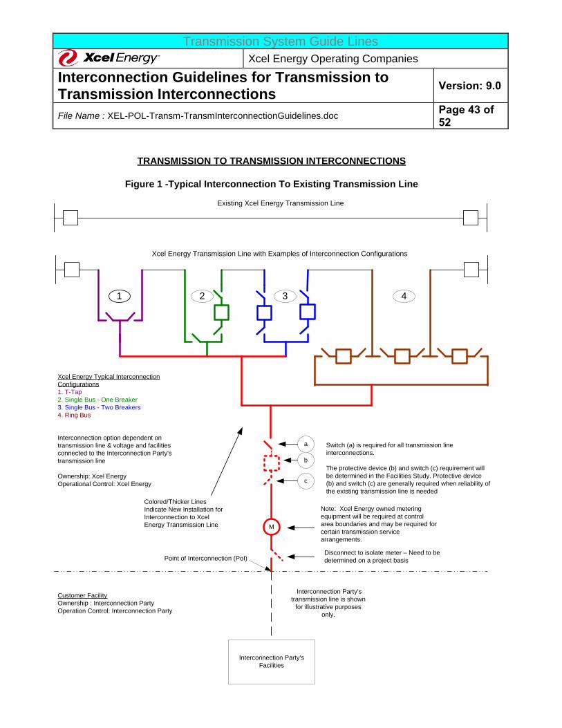
Transmission System Guide Lines
Xcel Energy Operating Companies
Interconnection Guidelines for Transmission to Transmission Interconnections
Version: 9.0
File Name : XEL-POL-Transm-TransmInterconnectionGuidelines.doc Page 43 of 52
Xcel Energy Transmission Line with Examples of Interconnection Configurations
Interconnection option dependent on
transmission line & voltage and facilities
connected to the Interconnection Party's
transmission line
Ownership: Xcel Energy
Operational Control: Xcel Energy
Xcel Energy Typical Interconnection
Configurations
1. T-Tap
2. Single Bus - One Breaker
3. Single Bus - Two Breakers
4. Ring Bus
M
Point of Interconnection (PoI)
TRANSMISSION TO TRANSMISSION INTERCONNECTIONS
Figure 1 -Typical Interconnection To Existing Transmission Line
Note: Xcel Energy owned metering
equipment will be required at control
area boundaries and may be required for
certain transmission service
arrangements.
Switch (a) is required for all transmission line
interconnections.
The protective device (b) and switch (c) requirement will
be determined in the Facilities Study. Protective device
(b) and switch (c) are generally required when reliability of
the existing transmission line is needed
Interconnection Party's
transmission line is shown
for illustrative purposes
only.
a
b
Customer Facility
Ownership : Interconnection Party
Operation Control: Interconnection Party
Interconnection Party's
Facilities
c
1 2 3 4
Existing Xcel Energy Transmission Line
Colored/Thicker Lines
Indicate New Installation for
Interconnection to Xcel
Energy Transmission Line
Disconnect to isolate meter – Need to be
determined on a project basis
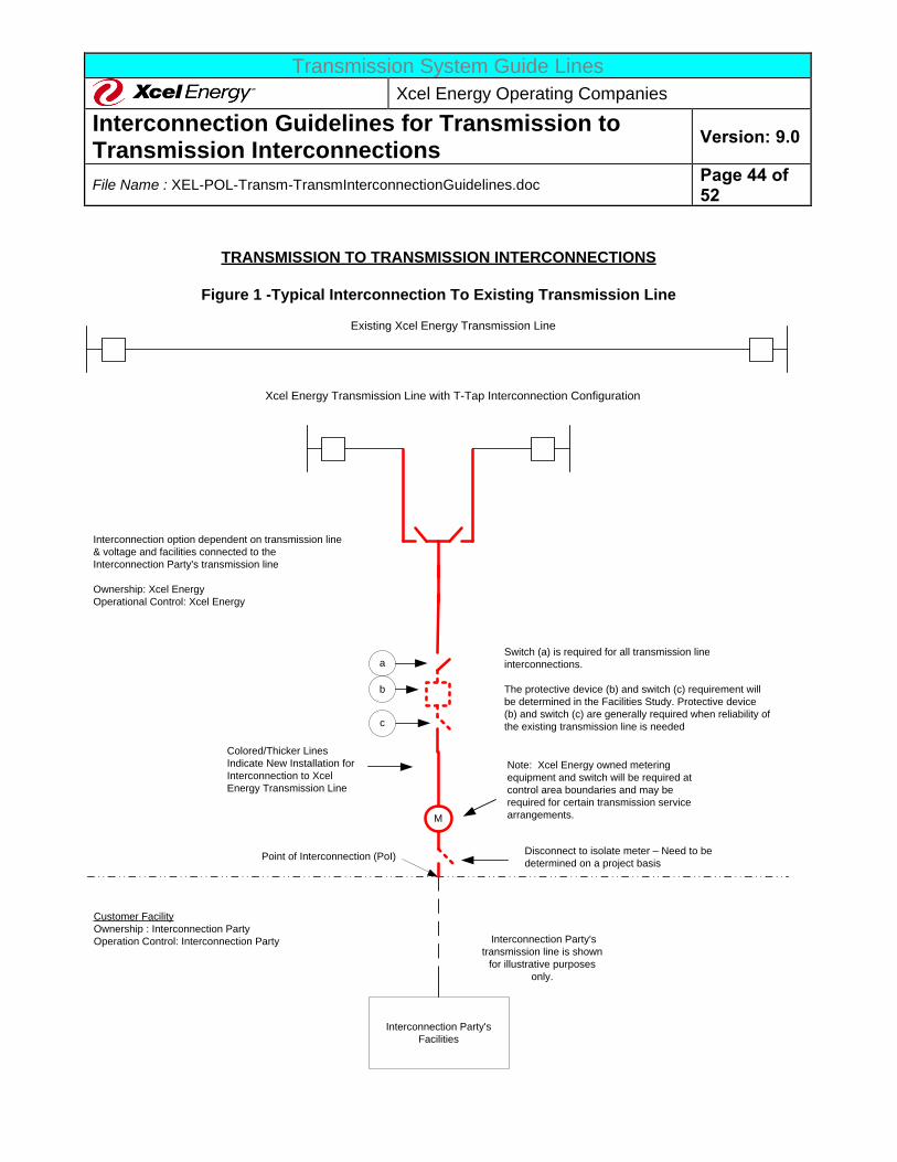
Transmission System Guide Lines
Xcel Energy Operating Companies
Interconnection Guidelines for Transmission to Transmission Interconnections
Version: 9.0
File Name : XEL-POL-Transm-TransmInterconnectionGuidelines.doc Page 44 of 52
Xcel Energy Transmission Line with T-Tap Interconnection Configuration
Interconnection option dependent on transmission line
& voltage and facilities connected to the
Interconnection Party's transmission line
Ownership: Xcel Energy
Operational Control: Xcel Energy
TRANSMISSION TO TRANSMISSION INTERCONNECTIONS
Figure 1 -Typical Interconnection To Existing Transmission Line
Interconnection Party's
transmission line is shown
for illustrative purposes
only.
Customer Facility
Ownership : Interconnection Party
Operation Control: Interconnection Party
Interconnection Party's
Facilities
Existing Xcel Energy Transmission Line
M
Point of Interconnection (PoI)
Note: Xcel Energy owned metering
equipment and switch will be required at
control area boundaries and may be
required for certain transmission service
arrangements.
Switch (a) is required for all transmission line
interconnections.
The protective device (b) and switch (c) requirement will
be determined in the Facilities Study. Protective device
(b) and switch (c) are generally required when reliability of
the existing transmission line is needed
a
b
c
Colored/Thicker Lines
Indicate New Installation for
Interconnection to Xcel
Energy Transmission Line
Disconnect to isolate meter – Need to be
determined on a project basis
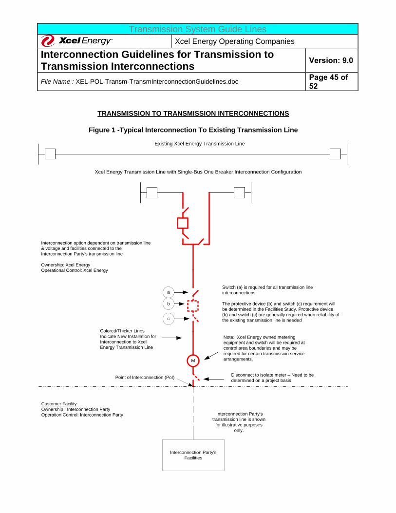
Transmission System Guide Lines
Xcel Energy Operating Companies
Interconnection Guidelines for Transmission to Transmission Interconnections
Version: 9.0
File Name : XEL-POL-Transm-TransmInterconnectionGuidelines.doc Page 45 of 52
Xcel Energy Transmission Line with Single-Bus One Breaker Interconnection Configuration
Interconnection option dependent on transmission line
& voltage and facilities connected to the
Interconnection Party's transmission line
Ownership: Xcel Energy
Operational Control: Xcel Energy
TRANSMISSION TO TRANSMISSION INTERCONNECTIONS
Figure 1 -Typical Interconnection To Existing Transmission Line
Interconnection Party's
transmission line is shown
for illustrative purposes
only.
Customer Facility
Ownership : Interconnection Party
Operation Control: Interconnection Party
Interconnection Party's
Facilities
Existing Xcel Energy Transmission Line
M
Point of Interconnection (PoI)
Note: Xcel Energy owned metering
equipment and switch will be required at
control area boundaries and may be
required for certain transmission service
arrangements.
Switch (a) is required for all transmission line
interconnections.
The protective device (b) and switch (c) requirement will
be determined in the Facilities Study. Protective device
(b) and switch (c) are generally required when reliability of
the existing transmission line is needed
a
b
c
Colored/Thicker Lines
Indicate New Installation for
Interconnection to Xcel
Energy Transmission Line
Disconnect to isolate meter – Need to be
determined on a project basis
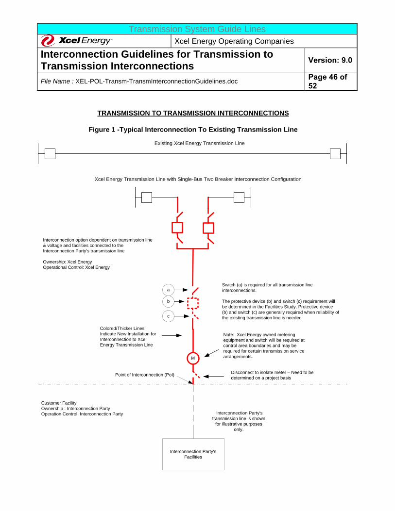
Transmission System Guide Lines
Xcel Energy Operating Companies
Interconnection Guidelines for Transmission to Transmission Interconnections
Version: 9.0
File Name : XEL-POL-Transm-TransmInterconnectionGuidelines.doc Page 46 of 52
Xcel Energy Transmission Line with Single-Bus Two Breaker Interconnection Configuration
TRANSMISSION TO TRANSMISSION INTERCONNECTIONS
Figure 1 -Typical Interconnection To Existing Transmission Line
Interconnection Party's
transmission line is shown
for illustrative purposes
only.
Customer Facility
Ownership : Interconnection Party
Operation Control: Interconnection Party
Interconnection Party's
Facilities
Existing Xcel Energy Transmission Line
M
Point of Interconnection (PoI)
Note: Xcel Energy owned metering
equipment and switch will be required at
control area boundaries and may be
required for certain transmission service
arrangements.
Switch (a) is required for all transmission line
interconnections.
The protective device (b) and switch (c) requirement will
be determined in the Facilities Study. Protective device
(b) and switch (c) are generally required when reliability of
the existing transmission line is needed
a
b
c
Colored/Thicker Lines
Indicate New Installation for
Interconnection to Xcel
Energy Transmission Line
Disconnect to isolate meter – Need to be
determined on a project basis
Interconnection option dependent on transmission line
& voltage and facilities connected to the
Interconnection Party's transmission line
Ownership: Xcel Energy
Operational Control: Xcel Energy
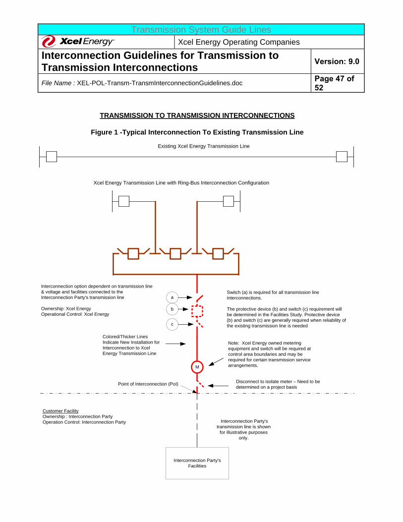
Transmission System Guide Lines
Xcel Energy Operating Companies
Interconnection Guidelines for Transmission to Transmission Interconnections
Version: 9.0
File Name : XEL-POL-Transm-TransmInterconnectionGuidelines.doc Page 47 of 52
Xcel Energy Transmission Line with Ring-Bus Interconnection Configuration
Interconnection option dependent on transmission line
& voltage and facilities connected to the
Interconnection Party's transmission line
Ownership: Xcel Energy
Operational Control: Xcel Energy
TRANSMISSION TO TRANSMISSION INTERCONNECTIONS
Figure 1 -Typical Interconnection To Existing Transmission Line
Interconnection Party's
transmission line is shown
for illustrative purposes
only.
Customer Facility
Ownership : Interconnection Party
Operation Control: Interconnection Party
Interconnection Party's
Facilities
Existing Xcel Energy Transmission Line
M
Point of Interconnection (PoI)
Note: Xcel Energy owned metering
equipment and switch will be required at
control area boundaries and may be
required for certain transmission service
arrangements.
Switch (a) is required for all transmission line
interconnections.
The protective device (b) and switch (c) requirement will
be determined in the Facilities Study. Protective device
(b) and switch (c) are generally required when reliability of
the existing transmission line is needed
a
b
c
Colored/Thicker Lines
Indicate New Installation for
Interconnection to Xcel
Energy Transmission Line
Disconnect to isolate meter – Need to be
determined on a project basis
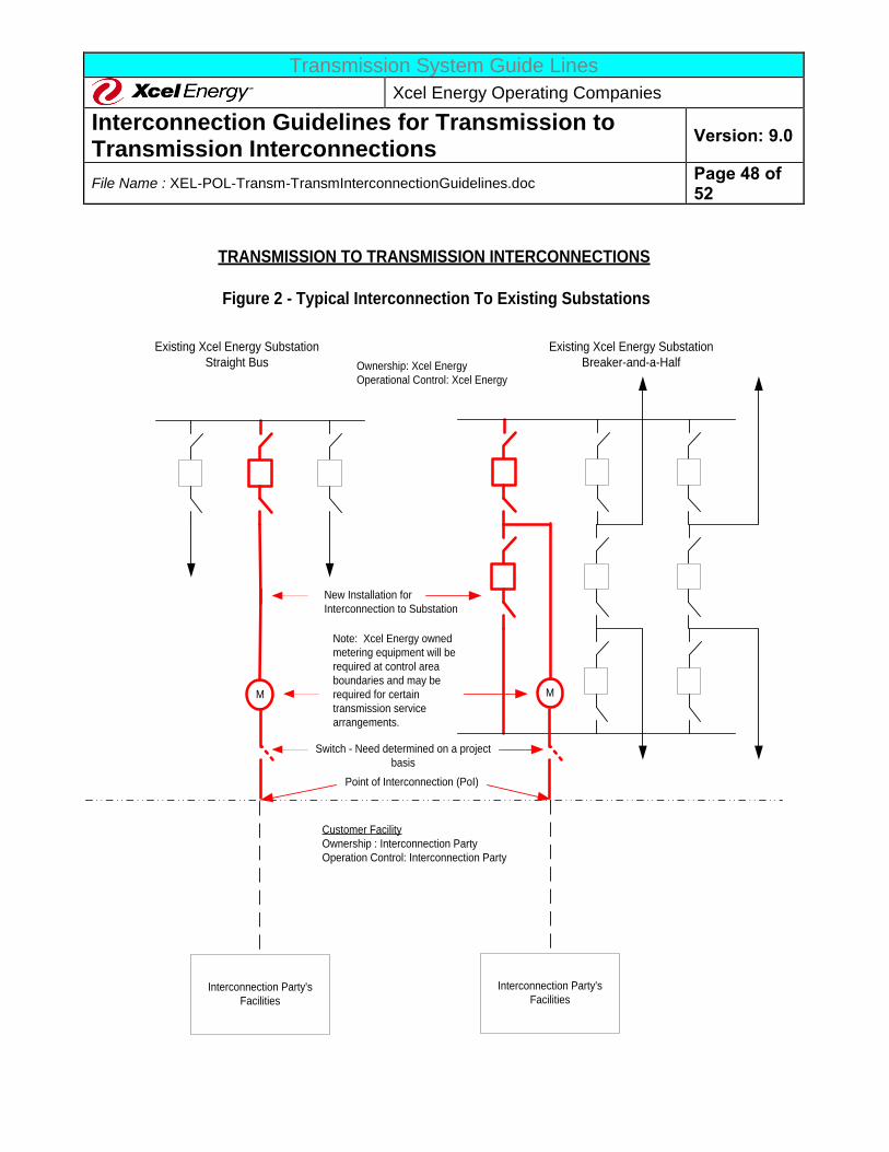
Transmission System Guide Lines
Xcel Energy Operating Companies
Interconnection Guidelines for Transmission to Transmission Interconnections
Version: 9.0
File Name : XEL-POL-Transm-TransmInterconnectionGuidelines.doc Page 48 of 52
M
Point of Interconnection (PoI)
Note: Xcel Energy owned
metering equipment will be
required at control area
boundaries and may be
required for certain
transmission service
arrangements.
Existing Xcel Energy Substation
Straight Bus
TRANSMISSION TO TRANSMISSION INTERCONNECTIONS
Figure 2 - Typical Interconnection To Existing Substations
Existing Xcel Energy Substation
Breaker-and-a-Half
M
Ownership: Xcel Energy
Operational Control: Xcel Energy
Customer Facility
Ownership : Interconnection Party
Operation Control: Interconnection Party
Interconnection Party's
Facilities
Interconnection Party's
Facilities
New Installation for
Interconnection to Substation
Switch - Need determined on a project
basis
Transmission System Guide Lines
Xcel Energy Operating Companies
Interconnection Guidelines for Transmission to Transmission Interconnections
Version: 9.0
File Name : XEL-POL-Transm-TransmInterconnectionGuidelines.doc Page 49 of 52
APPENDIX B: Xcel Energy Metering and Telemetry Requirements
1. General
The information in Appendix B outlines the requirements that shall apply for interconnecting the Customer to
the Xcel Energy System. In those cases where the Power Purchase Agreement, Interconnection Agreement, or Ancillary Services Agreement provisions differ from these requirements, the contract provisions shall take
precedence.
The meter installation will be capable of measuring Real Demand (Watts, kW, or MW), Reactive Demand (vars, Kvars, or Mvars), Voltage (V or kV), Current (A), Real Energy (Whr, kWhr, or MWhr), Reactive Energy (var-
hours, kvar-hours, or Mvar-hours), and possibly harmonics (voltage and current when required). The metering
shall have memory capable of a minimum of 4-channel, hourly data recording for 37 days. Additional channels for data recording may be required at the discretion of Xcel Energy (XE). The metering installation will
normally have remote dial-up data-retrieval capability. The XE required billing (revenue) meter, power quality metering (if required), instrument transformers (CTs, VTs) will be specified and owned by XE, but the
instrument transformers may be purchased and installed by the Customer or XE, as identified during the project
design phases, and determined on a case-by-case basis. XE will furnish meter and programs according to XE specifications.
2. Metering Accuracy, Testing, and Repair
A. METERING ACCURACY – REVENUE METERING
The metering shall have an accuracy of 0.5%. Any current or voltage transformers that are used for
metering will adhere to the “Accuracy Classifications for Metering” listed in ANSI C57.13. XE requires 3-
element metering accuracy for all circuits. The Voltage Transformers (VT) and Current Transformers (CT) must be metering accuracy class devices. Metering CTs and VTs are required to be independent of the
protection system CTs. As long as the burden is not determined by XE to be excessive, additional secondary windings on the VTs can be used for other purposes such as protective relaying. All of these VT
secondary supplies used for non-revenue metering purposes (e.g. relaying) shall be separately fused from
the metering VT secondary supplies.
All voltage and current transformers used for interconnect metering with continuous flows less than 20% of
full scale nameplate rating of the current transformers shall conform to 0.15% metering accuracy class or
better. All current transformers shall conform to ANSI metering accuracy class 0.3% for Burdens B0.1 thru
B1.8 and shall have a continuous current thermal rating factor (TRF) sized appropriately for the application.
All voltage transformers shall meet ANSI metering accuracy class 0.3% for all standard burdens. Note
that the metering used for local (panel) and remote (SCADA) indication and monitoring purposes does not
typically need to conform to the higher accuracy requirements of the revenue metering, and are typically supplied from the relaying accuracy CTs (bushing CTs), CVTs, etc.
Transmission System Guide Lines
Xcel Energy Operating Companies
Interconnection Guidelines for Transmission to Transmission Interconnections
Version: 9.0
File Name : XEL-POL-Transm-TransmInterconnectionGuidelines.doc Page 50 of 52
B. PERIODIC TESTING
The metering equipment shall be tested periodically, and re-calibrated or replaced to maintain the required
accuracy. The meter testing frequency shall at a minimum be based on current XE Practices and State or
Federal regulations. XE’s present testing practices are based on the type of metering situation and the jointly agreed to requirements of both parties involved. The Customer, at its option, may witness the
periodic testing. If the proposed date is not acceptable, then an alternative time acceptable to both parties must be worked out. The owner of the meter shall analyze and distribute any maintenance, repair, and test
results to all parties receiving the meter readings per the request of such parties.
C. METER AND TELEMETRY EQUIPMENT REPAIR
The owner of the metering and telemetry equipment is responsible for ensuring that the equipment is
adequately maintained and is repaired within a reasonable time after a failure is detected. The repair or replacement of a defective meter must be completed within 1 business day after it has been detected. All
changes, repairs, and replacements of the meter must be coordinated with the XE Meter Department.
3. Metering and Telemetry Function Requirements The meter and telemetry requirements define XE’s required functionality for meters, metering related
equipment (telephone lines, current transformers, voltage transformers, etc.), and telemetry equipment
(Remote Terminal Units [RTUs], transmitters, receivers, etc.). Major factors generally used to determine the type of metering and telemetry required include:
a. The type and size of the customer’s equipment.
b. The location of the customer on the XE System. c. The manner in which the installation will operate (one-way vs. two-way power flow).
d. Customer distribution connected generation
e. Customer desire to have other than XE provide ancillary services
Each request will be handled individually, and XE will solely determine the metering and telemetry modifications and/or additions required. All Transmission-to-Transmission interconnections will require a RTU circuit for the
installation of an RTU, Dual-Port RTU, Mini RTU, or any device that can provide this RTU functionality for Xcel
Energy Operations and Energy Accounting. At a minimum, the Customer will have to provide the Xcel Energy System Control Center real-time values for the MWs and Mvars from the revenue meter. ICCP data is not a
substitute for RTU requirements. XE will work with the customer to achieve an installation that meets the requirements of both the customer and XE. The metering requirements and cost responsibility will be stated in
the Interconnection Agreement.
In addition to providing real-time revenue meter values to the Xcel Energy System Control Center, the Customer
must provide a phone line or other suitable communication channel to allow the revenue meter data to be periodically retrieved by Xcel Energy. This periodic retrieval will happen at least once per month.
If the Interconnection is outside XE’s balancing area, the utility within whose balancing area the interconnection
resides may have specific metering and telemetry requirements to which the Customer must adhere. Upon the
Transmission System Guide Lines
Xcel Energy Operating Companies
Interconnection Guidelines for Transmission to Transmission Interconnections
Version: 9.0
File Name : XEL-POL-Transm-TransmInterconnectionGuidelines.doc Page 51 of 52
start of the Facilities Study, XE will notify the customer of any other utility who may need to be involved in the
metering and telemetry design and approval. If the interconnection is not within either XE’s service territory or XE’s balancing area, the following metering and telemetry requirements may not apply
A. REAL-TIME MEASURED VALUES AND METERING REQUIRED
Real Energy Usage (Watt-hours)
Power factor or Reactive Energy Usage (Power Factor, VARhours, or Q-hours)
Interval Recorder to capture hourly energy use (some meters provide this capability within
the meter and is an acceptable substitute) RTU functionality and communication circuit to provide these values to the Xcel Energy
System Control Center.
The ability and communication channel for XE to remotely interrogate the meter and data
B. ADDITIONAL MEASURED VALUES, METERING, AND TELMETRY WHEN TELEMETRY
EQUIPMENT IS REQUIRED
Status of high side interrupting and/or disconnecting device
Real Power Flow (Watts)
Reactive Power Flow (VARs), at XE’s discretion
Voltage (steady state 60 Hz and possibly transients) at the point of connection to XE
(Volts), at XE’s discretion
Amps at the point of connection to XE
Harmonics – voltage and current (if PQM meter is required)
Remote Terminal Unit or Data Link to telemeter all measured values to XE’s Energy
Management System. This will also capture the hourly energy usage by reading the MWH values.
Recording and communication of the data to XE’s EMS through a dedicated communication medium a minimum of every 24 seconds.
C. METERING CONFIGURATION
The Typical Metering Installation (see Figure C-1) will be used when XE serves the load requirements of the
Customer directly. Each specific situation will be evaluated for cost effective metering.
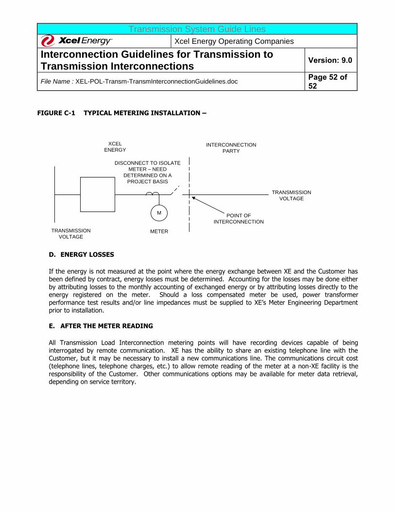
Transmission System Guide Lines
Xcel Energy Operating Companies
Interconnection Guidelines for Transmission to Transmission Interconnections
Version: 9.0
File Name : XEL-POL-Transm-TransmInterconnectionGuidelines.doc Page 52 of 52
FIGURE C-1 TYPICAL METERING INSTALLATION –
M
METER
POINT OF
INTERCONNECTION
XCEL
ENERGYINTERCONNECTION
PARTY
TRANSMISSION
VOLTAGE
TRANSMISSION
VOLTAGE
DISCONNECT TO ISOLATE
METER – NEED
DETERMINED ON A
PROJECT BASIS
D. ENERGY LOSSES
If the energy is not measured at the point where the energy exchange between XE and the Customer has been defined by contract, energy losses must be determined. Accounting for the losses may be done either
by attributing losses to the monthly accounting of exchanged energy or by attributing losses directly to the energy registered on the meter. Should a loss compensated meter be used, power transformer
performance test results and/or line impedances must be supplied to XE’s Meter Engineering Department prior to installation.
E. AFTER THE METER READING
All Transmission Load Interconnection metering points will have recording devices capable of being
interrogated by remote communication. XE has the ability to share an existing telephone line with the Customer, but it may be necessary to install a new communications line. The communications circuit cost
(telephone lines, telephone charges, etc.) to allow remote reading of the meter at a non-XE facility is the
responsibility of the Customer. Other communications options may be available for meter data retrieval, depending on service territory.