Embed Size (px)
DESCRIPTION
Using 2D Finite Element Analysis to create a sub-surface plane/curve in Xdisp
Citation preview

Using 2D Finite Element Analysis to create a sub-surface plane/curve in Xdisp
1. Introduction
Carrying out a two dimensional (2D) finite element (FE) analysis specific for the proposed
installation of a retaining wall and subsequent retained cut excavation is one method to enable
the user to create sub-surface ground movement plane in Xdisp.
A 2D analysis would typically calculate ground movements considering either a plane strain
or axi-symmetric assumption.
One of the main advantages of importing sub-surface planes of displacement from FE
analysis is that the ground movement results can be combined with movements from other
excavations such as those from tunnels calculated by Xdisp. The combined effect can then be
appraised and impacts on 3rd
party assets such as buildings, utilities or tunnels appraised.
Other uses could be to generate an estimate of three dimensional displacements around a deep
basement excavation from a two dimensional analysis based upon an empirical methodology
that has been programmed into Xdisp.
The term ‘ground movement plane’ in this section of text is used to describe a vertical plane
or grid of settlement or horizontal ground movement results. These can be tabulated in terms
of the x and y co-ordinate of the displacement calculation point and magnitude of
displacement.
2D FE analyses generally model a number of construction stages and any of these could be
input into Xdisp dependent upon the desired ground movement results required. Sub-surface
planes of displacement from different stages can be imported into Xdisp, for instance to
reflect the effect of installing piles or completion of the excavation.
Care should be taken if using results from two or more stages from the FE analysis that the
cumulated displacements proposed for use in Xdisp are appropriate. For instance, unless
displacements are zeroed at a given stage of a FE analysis, displacements are carried through
from previous stages.
Consideration should also be given to the use of appropriate soil models in the FE analysis
that has been calibrated to the ground conditions and enable appropriate calculation of ground
movements.
Several common applications are anticipated for importing sub-surface planes of
displacement from a 2D finite element analyses. These include:
• Modelling installation of an embedded retaining wall. Often a stage is included in a
finite element analysis prior to installing the retaining wall for relaxation of the
ground as a consequence of wall installation. The user of Xdisp could then apply the
calculated plane to the length of wall specified in Xdisp
• Modelling excavation induced displacements from an axi-symmetric shaft analysis.
The user of Xdisp could then apply the calculated planes of displacement around the
defined shaft position in Xdisp.
• Modelling excavation induced displacements from a basement or embedded retaining
wall analysis. Where a plane strain 2D analysis has been carried out and the corners
of an excavation are considered to have a stiffening effect, the empirical method
proposed by Fuentes & Devriendt (2010) has been programmed into Xdisp to allow
an estimate of three dimensional displacements to be calculated around the proposed
excavation.

Procedures are provided below for the import of displacements from a 2D FE analysis for
import of pile installation and excavation induced embedded retaining wall analysis.
These would be used to create the sub surface curves as detailed below.
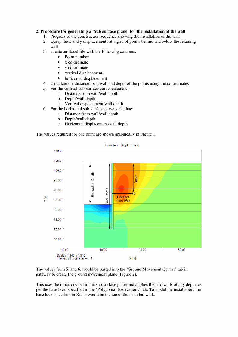
2. Procedure for generating a ‘Sub surface plane’ for the installation of the wall 1. Progress to the construction sequence showing the installation of the wall
2. Query the x and y displacements at a grid of points behind and below the retaining
wall
3. Create an Excel file with the following columns:
• Point number
• x co-ordinate
• y co-ordinate
• vertical displacement
• horizontal displacement
4. Calculate the distance from wall and depth of the points using the co-ordinates
5. For the vertical sub-surface curve, calculate:
a. Distance from wall/wall depth
b. Depth/wall depth
c. Vertical displacement/wall depth
6. For the horizontal sub-surface curve, calculate:
a. Distance from wall/wall depth
b. Depth/wall depth
c. Horizontal displacement/wall depth
The values required for one point are shown graphically in Figure 1.
The values from 5. and 6. would be pasted into the ‘Ground Movement Curves’ tab in
gateway to create the ground movement plane (Figure 2).
This uses the ratios created in the sub-surface plane and applies them to walls of any depth, as
per the base level specified in the ‘Polygonial Excavations’ tab. To model the installation, the
base level specified in Xdisp would be the toe of the installed wall..
Excavation D
epth
Wall
Depth
Depth
Distance from Wall

An appropriate order of x and y polynomial should be selected to obtain an appropriate fit to
the imported data. A check should be carried out to confirm the polynomials proposed in
Xdisp adequately replicate the input data.
Figure 2 – Xdisp input for sub-surface curve

3. Sub surface curve for the excavation 1. Progress to the construction sequence showing the excavation
2. Query the x and y displacements at a grid of points behind and below the retaining
wall
3. Create an Excel file with the following columns:
• point number
• x co-ordinate
• y co-ordinate
• vertical displacement
• horizontal displacement
4. Calculate the distance from wall and depth of the points using the co-ordinates
5. For the vertical sub-surface curve, calculate:
a. Distance from wall/excavation depth
b. Depth/excavation depth
c. Vertical displacement/excavation depth
6. For the horizontal sub-surface curve, calculate:
a. Distance from wall/excavation depth
b. Depth/excavation depth
c. Horizontal displacement/excavation depth
The values required for one point are shown graphically in Figure 1.
The values from 5. and 6. would be pasted into the sub-surface curve tab in gateway to create
the curve (Figure 2).
To model the excavation, the base level specified in Xdisp would be the base of the
excavation (not the installed wall).
An appropriate order of x and y polynomial should be selected to obtain an appropriate fit to
the imported data. A check should be carried out to confirm the polynomials proposed in
Xdisp adequately replicate the input data.


![Basements Questions and Matters 170216transact.westminster.gov.uk/.../basements_questions_and_matters... · [B/EB/10] on the creation of a sub-basement beneath a listed building,](https://img.pdfslide.net/doc/110x75/5ea59abc58438277214ef444/basements-questions-and-matters-beb10-on-the-creation-of-a-sub-basement-beneath.jpg)


![Draconem Sub-Sector - WordPress.com · 2017. 6. 8. · Introduction Welcome to the Draconem sub-sector! This creation is something that I began on my blog [] as a discussion of science](https://img.pdfslide.net/doc/110x75/6114f86c1319dd02d2618308/draconem-sub-sector-2017-6-8-introduction-welcome-to-the-draconem-sub-sector.jpg)