Embed Size (px)
Citation preview

1
Introduction to
Digital Subscriber’s Line (DSL)
Professor Fu Li, Ph.D., P.E. ©
xDSL Technology
Transmission Modes• Direction• Timing • Channels • Single or Multiple Points
2
xDSL Technology
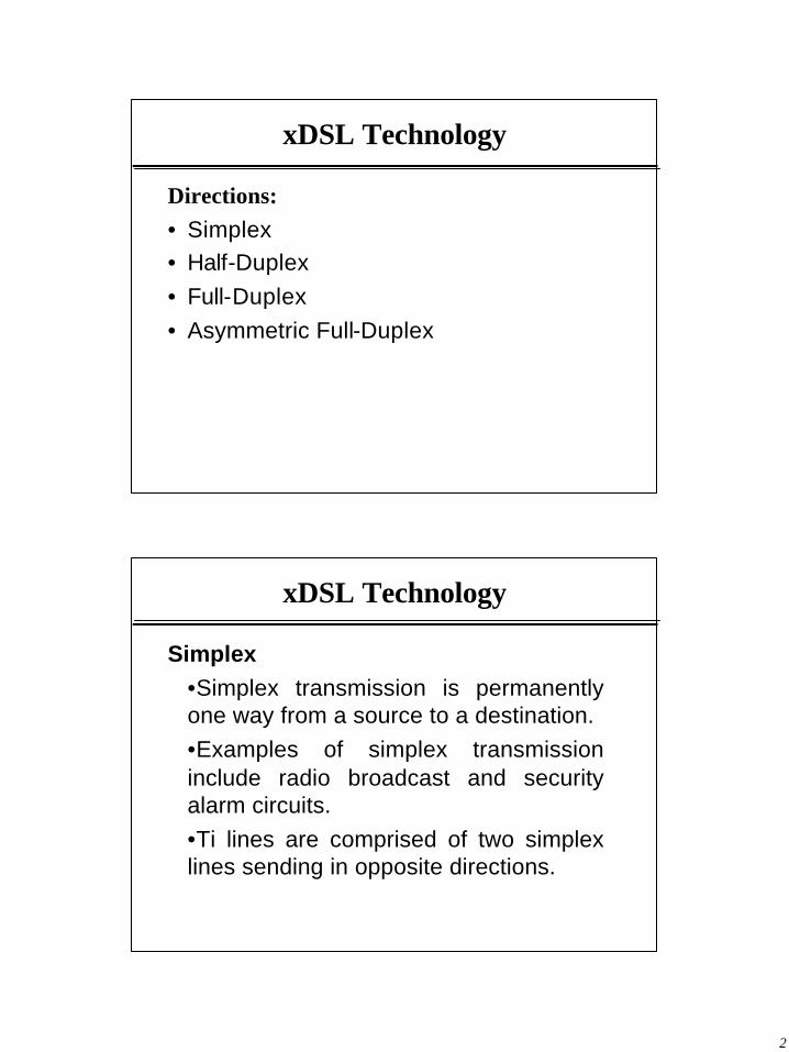
Directions:• Simplex• Half-Duplex• Full-Duplex• Asymmetric Full-Duplex
xDSL Technology
Simplex•Simplex transmission is permanently one way from a source to a destination. •Examples of simplex transmission include radio broadcast and security alarm circuits.•Ti lines are comprised of two simplex lines sending in opposite directions.
3
xDSL Technology
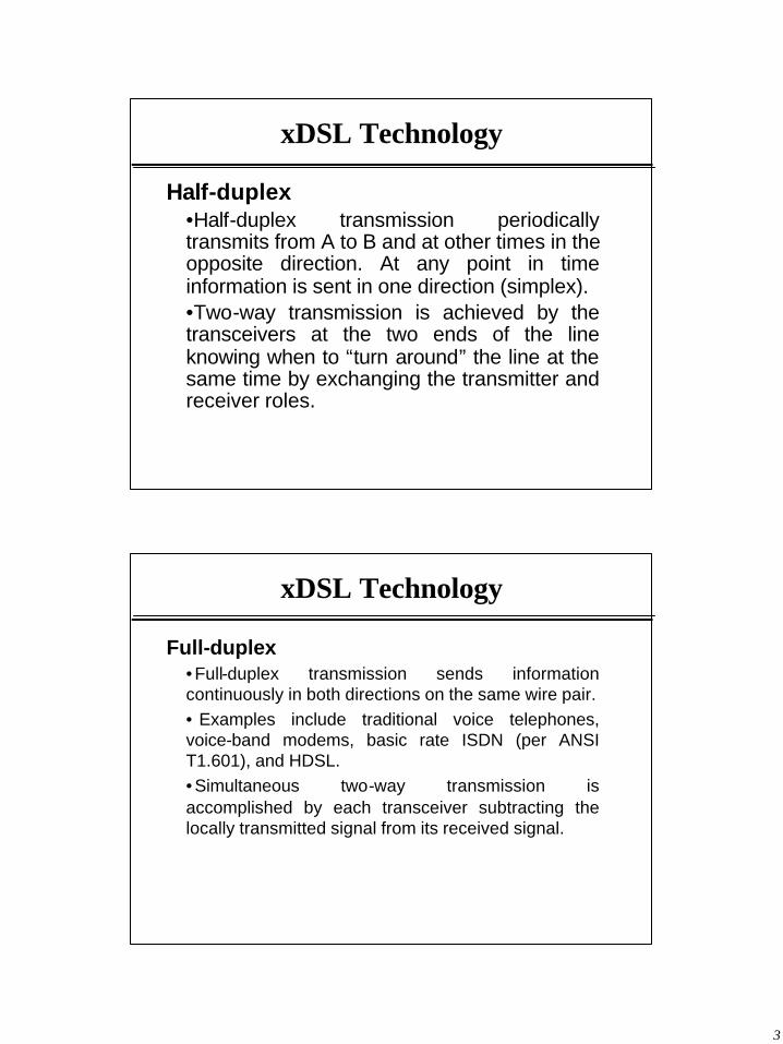
Half-duplex•Half-duplex transmission periodically transmits from A to B and at other times in the opposite direction. At any point in time information is sent in one direction (simplex). •Two-way transmission is achieved by the transceivers at the two ends of the line knowing when to “turn around” the line at the same time by exchanging the transmitter and receiver roles.
xDSL Technology
Full-duplex• Full-duplex transmission sends information continuously in both directions on the same wire pair.• Examples include traditional voice telephones, voice-band modems, basic rate ISDN (per ANSI T1.601), and HDSL. • Simultaneous two-way transmission is accomplished by each transceiver subtracting the locally transmitted signal from its received signal.

4
xDSL Technology
Asymmetric Full-duplex• An asymmetric version of full-duplex transmission is used by asymmetric digital subscriber line (ADSL). • Information is sent in both directions simultaneously, but the data rate downstream (towards the customer) is much greater than the upstream (towards the network) data rate.• This permits high downstream data rates on much longer lines by reducing the nearend crosstalk (NEXT) between ADSLs.
xDSL Technology
Timing •Synchronous and asynchronous transmission may apply for simplex, half-duplex, and full-duplex transmission. In general, DSLs use synchronous, not asynchronous transmission.•Synchronous•Asynchronous

5
xDSL Technology
Synchronous Timing •Synchronous transmission sends bits at a continuous rate. DSL receivers usually derive their timing from the periodicity of the received bit transitions
xDSL Technology
Asynchronous Timing •Asynchronous transmission sends units (characters or blocks) with a unique flag signal to mark the start of each unit.
6
xDSL Technology
Channels•DSLs must convey more than one channel of information, where each channel is for different applications or services. •Time-Division Multiplexing•Frequency-Division Multiplexing•Space-Division Multiplexing•Code-Division Multiplexing
xDSL Technology
Time-Division Multiplexing (TDM)• Information is organized into fixed-length
frames with a fixed number of bits allocated to each channel.
• Frames may be organized into super-frames to accommodate low-bit-rate channels such as an embedded operations channel.
7
xDSL Technology
Frequency-Division Multiplexing (FDM)• Frequency division multiplexing (FDM) places
each channel in a separate frequency band. • Thus, all channels are sent at the same time. • FDM duplexing also virtually eliminates
NEXT.
xDSL Technology
Space-Division Multiplexing (SDM)• Space division multiplexing simply places each channel on a separate set of wires. • This simplicity is appropriate for sending signals over distances measured in centimeters, but the cost of wires and the additional transceivers for each set of wires quickly becomes expensive.

8
xDSL Technology
Code-Division Multiplexing (CDM)• Code division multiplexing simply encodes each channel on an orthogonal codes. • Widely used in military communications and wireless commutations (for higher capacity)• The discussion above applies for the physical level. At the logical level, where theinformation flow at higher protocols is considered, point-to-point and multipoint information flow may occur via any physical topology.
xDSL Technology
Single and Multipoint Topologies •Point-to-point: one transceiver is connected to each of the two ends of a pair of wires. •Point-to-multipoint systems consist of a central (master) station transceiver, which communicates with multiple directly connected terminals.
9
xDSL Technology
Point-to-point•Point-to-point: one transceiver is connected to each of the two ends of a pair of wires. •One end may be located at a telephone company site such as a Central Office, and the other end may be located at a customer premises. •DSLs are point-to-point transmission systems.
xDSL Technology
Point-to-multipoint•Point-to-multipoint systems consist of a central (master) station transceiver, which communicates with multiple directly connected terminals. •One end may be located at a telephone company site such as a Central Office, and the other end may be located at a customer premises.

10
xDSL Technology
Coding and Modulation Techniques• 2B1Q (2-Binary 1-Quaternary)• QAM (Quatrature Amplitude
Modulation)• CAP (Carrier-less Amplitude Phase
Modulation)• DMT (Discrete Multi-Tone)• TC-PAM (Trellis Coded Pulse Amplitude
Modulation
Coding/Modulation Techniques: 2P1Q
2B1Q (2-Binary 1-Quaternary)• 2B1Q is a 4-level code that encodes two bits at
one time.• Each level represents two bits of data.

11
Coding/Modulation Techniques: 2P1Q
Example: • Transmitting ASCII Symbol “J” • In 2B1Q it is 01110100• then the output waveform
Coding/Modulation Techniques: 2P1Q
Advantage of using a 2B1Q scheme to encode data is that
• it is easy to understand and implement and • does not suffer badly from NEXT (Near
End Cross Talk).• However, it does not make as efficient use
of the available bandwidth as some other encoding techniques.

12
Coding/Modulation Techniques: QAM
QAM (Quadrature Amplitude Modulation). • Similar to 2B1Q encoding in the fact that
multiple bits of data coded into each symbol that is sent over the line.
• QAM modulates both the amplitude and phase angle of the signal.
• QAM encoding can be represented by the constellation of points shown next.
Coding/Modulation Techniques: QAM
QAM can be understood • as two-dimensional PAM with
each of the two carriers (having 90º phase-offset) being used with one-dimensional PAM.
• as a two-dimensional constellation of signal points where the extension in each dimension depends on the number of signaling levels of the one-dimensional PAM.
13
Coding/Modulation Techniques: QAM
• Increasing the size of signal constellation has the same effects as an increase of the number of signal levels in a PAM-system.
• Therefore a careful trade-off between used bandwidth and necessary signal to noise ratio, in order to reliably transmit the chosen constellation, has to be done.
• There is a cost of about 3 dB for the transmission of an additional bit per symbol (therefore 6 dB for additional two bits)
Coding/Modulation Techniques: QAM
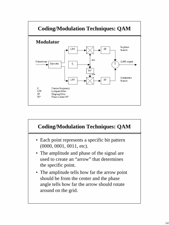
• QAM uses the effect that two signals, with same carrier frequency but being modulated onto a sine and a cosine carrier, do not influence each other in ideal environment.
• This fact is especially easy to understand for the case of digital transmission and a sampling rate double as high as the carrier frequency.
14
Coding/Modulation Techniques: QAM
Modulator
Coding/Modulation Techniques: QAM
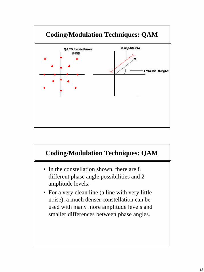
• Each point represents a specific bit pattern (0000, 0001, 0011, etc).
• The amplitude and phase of the signal are used to create an “arrow” that determines the specific point.
• The amplitude tells how far the arrow point should be from the center and the phase angle tells how far the arrow should rotate around on the grid.
15
Coding/Modulation Techniques: QAM
Coding/Modulation Techniques: QAM
• In the constellation shown, there are 8 different phase angle possibilities and 2 amplitude levels.
• For a very clean line (a line with very little noise), a much denser constellation can be used with many more amplitude levels and smaller differences between phase angles.

16
Coding/Modulation Techniques: CAP
Carrierless amplitude phase modulation (CAP)
• CAP is a special form of QAM that is especially suitable for fully digital implementation.
• The transmit signals of a QAM- and a CAP-system are about equal.
• The difference lies mainly in the way they are implemented.
Coding/Modulation Techniques: CAP
• QAM is implemented with two explicit carriers (same frequency, 90º phase-offset, therefore orthogonality) that are modulated in a multiplier with the output of the state encoder,
• CAP modulation is being done in a Hilbert filter pair. The outputs of the state encoder (in-phase and quadrature) are directly used as inputs for a Hilbert filter pair that is used for modulation.
• The amplitude responses of the envelopes of the two filters are equal but the phase responses have an offset of 90º

17
Coding/Modulation Techniques: CAP
CAP Modulator
• The amplitude responses of the envelopes of the two filters are equal but the phase responses have an offset of 90º
Coding/Modulation Techniques: CAP
Hilbert Filter (impulse response)
• In-Phase
• Quadrature
18
Coding/Modulation Techniques: CAP
• In CAP, phase and amplitude of a pair of equal-frequency signals are varied to create between four and 1024 discrete line conditions, or symbols.
• Each symbol represents several bits, the actual number being dependent on the total number of possibilities.
• For example, CAP-16 uses 12 different phases and then adds a further four symbols by repeating four of the phases but at half amplitude. A total of 16 combinations of bit patterns, starting from 0000 and ending with 1111, can be represented
Coding/Modulation Techniques: CAP
Price for this efficiency:• The greater the number of bits carried by
each symbol, the quieter the transmission channel must be.
• In the case of CAP-4, with the phases 90 degrees apart, up to about 40 degrees of peak phase noise could be tolerated without causing any errors.
• For CAP-12, the phase jitter would have to be below 10 degrees

19
Coding/Modulation Techniques: CAP
In CAP,• only the sidebands carry any useful
information;• the carrier is suppressed (hence the
term carrierless); and • only the sidebands are transmitted.
Coding/Modulation Techniques: CAP
CAP Advantages:• possibility to implement it completely in
digital fashion (except for the finalbandpass filter).
• A second advantage of CAP in relation to QAM is the absence of phase rotators, being sensitive to jitter.

20
Coding/Modulation Techniques: CAP
• Equalization is done similarly to the proceedings, already described for the QAM-system. Also
• the performance of a CAP-system is equal to the one of a QAM-system.
• The main advantage of CAP over QAM is therefore the ease of digital implementation.
Coding/Modulation Techniques: DMT
DMT (Discrete Multi-Tone) is a form of • multi-carrier modulation in which the original
spectrum of the input signal is spread over numerous bands, each of which are independently modulated to some carrier frequency.

21
Coding/Modulation Techniques: DMT
DMT (Discrete Multi-Tone)
• divide the frequency band into 256 sub-channels that are about 4 kHz wide.
• 32 of these channels are reserved for upstream data.
• Each channel independently sends data using QAM encoding (Quadrature Amplitude Modulation).
Coding/Modulation Techniques: DMT
DMT at the transmitter, • a block of bits is encoded as a set of QAM sub-
symbols, as inputs to an inverse Fourier transform (IFFT) which combines the complex sub-symbols into a set of real-valued time domain samples.
• In practice, the subchannels are not completely independent so a number of time domain samples are prefixed to the output of the IFFT. Cyclic prefix is used to remove ISI between subchannels.
• The time domain samples are then passed to a D/A converter, low-pass filtered, and sent on tchannel.

22
Coding/Modulation Techniques: DMT
DMT transmitter
Coding/Modulation Techniques: DMT
DMT in the receiver, the reverse process is performed. The signal is passed through an A/D, the cyclic prefix (if any) is removed, the data are input to the FFT, and a decoder recognizes the QAM symbol as a certain bit stream.

23
Coding/Modulation Techniques: DMT
Coding/Modulation Techniques: DMT
DMT eliminates need for most adaptive equalization based on the condition that the frequency response of the channel be nearly constant across any sub-channel. But there may still be need for equalization such as
Before After

24
Coding/Modulation Techniques: DMT
DMT• each of the 256 different sub-channels will
have different amounts of noise• DMT allows each channel to use a different
QAM constellation. – At low frequencies, the line usually has fewer
problems than at high frequencies, so a denser constellation with more points can be used.
– Noisier channels will transmit fewer bits per symbol, or channels may not be used at all if there is too much interference.
Coding/Modulation Techniques: DMT
DMT
• Since the condition of each channel may change over time, the ADSL modem constantly must adapt it’s signal processing to accommodate these changes.

25
Coding/Modulation Techniques: DMT
DMT
Coding/Modulation Techniques: DMT
DMT (downside stories)
• The upstream DMT algorithm can produce significant NEXT (near-end cross-talk), which can interfere with the lower downstream bands.
• These bands could be turned off and not used to avoid the noise, but by doing that bandwidth for downstream data is decreased.
26
Coding/Modulation Techniques: DWMT
DWMT (Discrete Wavelet Multi-Tone) is a • a variation of DMT with superior sub-channel
isolation. • modulation technique based on wavelet filter
banks. • produces superior performance in real world,
noisy environments. • DWMT technology is developed for VDSL
applications as well as telephone service distribution over cable TV networks.
Coding/Modulation Techniques: DWMT
DWMT • uses an wavelet transform instead of the
Fourier transform used in OFDM and DMT. • subchannels have sidelobes lower than DMT
and more closely approximate the ideal. • DWMT sidelobes are 45dB below mainlobe
while OFDM and DMT sidelobes are only 13 dB down,
• 99.997% of the DWMT subchannel power resides in the main lobe while only about 91% of OFDM and DMT subchannel power resides in main lobe.
27
Coding/Modulation Techniques: DWMT
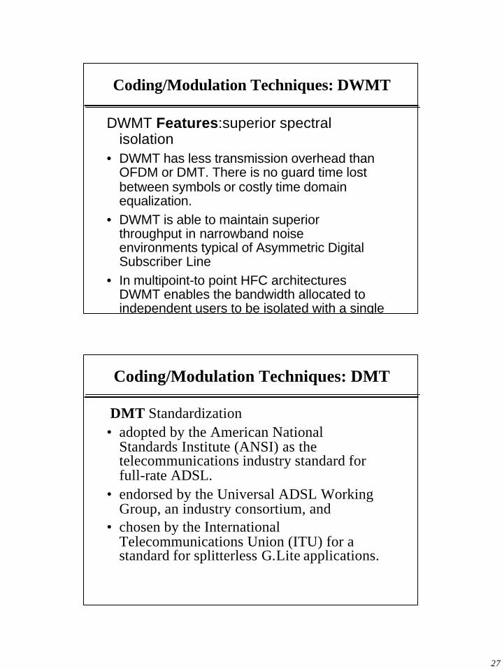
DWMT Features:superior spectral isolation
• DWMT has less transmission overhead than OFDM or DMT. There is no guard time lost between symbols or costly time domain equalization.
• DWMT is able to maintain superior throughput in narrowband noise environments typical of Asymmetric Digital Subscriber Line
• In multipoint-to point HFC architectures DWMT enables the bandwidth allocated to independent users to be isolated with a single
Coding/Modulation Techniques: DMT
DMT Standardization• adopted by the American National
Standards Institute (ANSI) as the telecommunications industry standard for full-rate ADSL.
• endorsed by the Universal ADSL Working Group, an industry consortium, and
• chosen by the International Telecommunications Union (ITU) for a standard for splitterless G.Lite applications.
28
Coding/Modulation Techniques: DMT Vs. CAP
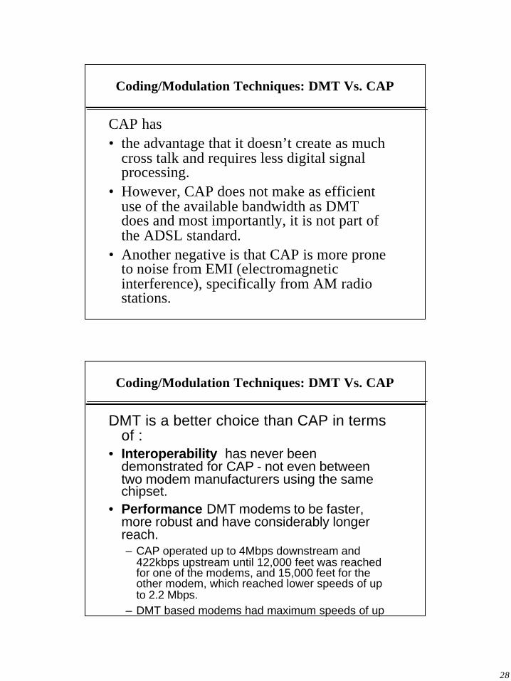
CAP has • the advantage that it doesn’t create as much
cross talk and requires less digital signal processing.
• However, CAP does not make as efficient use of the available bandwidth as DMT does and most importantly, it is not part of the ADSL standard.
• Another negative is that CAP is more prone to noise from EMI (electromagnetic interference), specifically from AM radio stations.
Coding/Modulation Techniques: DMT Vs. CAP
DMT is a better choice than CAP in terms of :
• Interoperability has never been demonstrated for CAP - not even between two modem manufacturers using the same chipset.
• Performance DMT modems to be faster, more robust and have considerably longer reach. – CAP operated up to 4Mbps downstream and
422kbps upstream until 12,000 feet was reached for one of the modems, and 15,000 feet for the other modem, which reached lower speeds of up to 2.2 Mbps.
– DMT based modems had maximum speeds of up to 8 Mbps/768kbps and achieved higher speeds

29
Coding/Modulation Techniques: DMT Vs. CAP
• Spectral compatibility defines how much energy a system will put out - this controls to what extent it will interfere with other systems.– CAP is not as spectrally compatible as DMT and
will cause significant cross talk and interference into others.
– CAP is less efficient because it requires more space and signal power to get the same data rate.
• Noise Immunity adapts signal to match channel. – DMT transmitter can easily monitor the channel
and then adapt its transmission to characteristics of phone line, and continuously updates to maintain optimum.
– CAP systems cannot modify its transmitter and so it needs to try to undo all the attenuation and
Coding/Modulation Techniques: DMT Vs. CAP
• Power Consumption, misconception that DMT uses more power than CAP.CAP may actually require more than DMT, since it is more wasteful.
• Robustness and Error Correction– CAP chipset, which supports error correction only
on the downstream. – DMT uses error correction as a potent technique
to improve performance and efficiency at low cost. • Rate Adaptivity
– DMT is inherently and straightforwardly rate adaptive, and has always been so. DMT achieves rate adaption easily and flexibly.
– CAP can support rate adaption only by varying the constellation and bandwidth of a single carrier.

30
DSL Access Multiplexer (DSLAM)
DSLAM (DSL Access Multiplexer )• delivers exceptionally high-speed data
transmission over existing copper telephone lines;
• separates the voice-frequency signals from the high-speed data traffic and controls and
• routes digital subscriber line (xDSL) traffic between the subscriber's end-user equipment (router, modem, or network interface card [NIC]) and the network service provider's network.
DSL Access Multiplexer (DSLAM)
DSLAM (DSL Access Multiplexer ) located in CO to interact with the customer premises equipment (CPE) at the end-user location.
• delivers exceptionally high-speed data transmission over existing copper telephone lines;
• separates the voice-frequency signals from the high-speed data traffic and controls and
• routes digital subscriber line (xDSL) traffic between the subscriber's end-user equipment (router, modem, or network interface card [NIC]) and the network service provider's network.

31
DSL Access Multiplexer (DSLAM)
• A multiservice DSLAM is a broadband-access element combines support for multi-DSL types.
• When coupled with high-capacity ATM switching,DSLAMs deliver scalability, port density, and a redundant architecture for reliability.
• DSLAMs often allow for full ATM switching, traffic management, and quality of service (QoS), in addition to the delivery of a full range of services.
• These services include analog, ISDN, IDSL, SDSL, rate-adaptive DSL–competive access provider (RADSL–CAP), and RADSL–discretemultitone (DMT) on a single platform.
DSL Access Multiplexer (DSLAM)
• The multiservice DSLAM can also be configured to add value in the form of routing and security functionality.
• The device is intended to enable service providers to optimize the bandwidth of existing infrastructure as well as deliver high-speed, integrated services over a single physical-access medium.
• DSLAM Scalability: Avoiding the Hidden Costs of DSL Deployment
32
DSL Access Multiplexer (DSLAM)
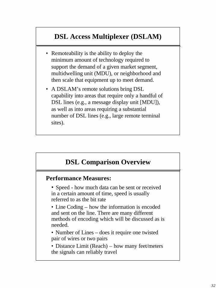
• Remoteability is the ability to deploy the minimum amount of technology required to support the demand of a given market segment,multidwelling unit (MDU), or neighborhood and then scale that equipment up to meet demand.
• A DSLAM’s remote solutions bring DSL capability into areas that require only a handful of DSL lines (e.g., a message display unit [MDU]), as well as into areas requiring a substantial number of DSL lines (e.g., large remote terminal sites).
DSL Comparison Overview
Performance Measures:� • Speed - how much data can be sent or received
in a certain amount of time, speed is usually referred to as the bit rate
� • Line Coding – how the information is encoded and sent on the line. There are many different methods of encoding which will be discussed as is needed.
� • Number of Lines – does it require one twisted pair of wires or two pairs
� • Distance Limit (Reach) – how many feet/meters the signals can reliably travel
33
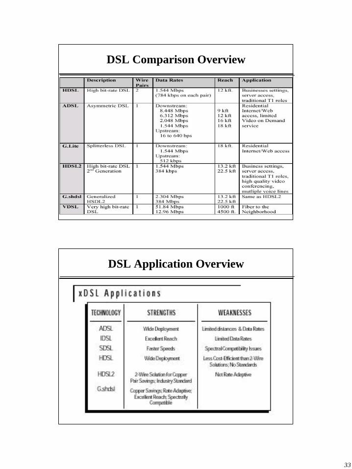
DSL Comparison Overview
DSL Application Overview